Article

Neuroevolutionary Control for Autonomous Soaring

Department of Mechanical and Aerospace Engineering, Royal Military College of Canada, P.O. Box 17000, Kingston, ON K7K 7B4, Canada
*
Author to whom correspondence should be addressed.
Aerospace 2021, 8(9), 267; https://doi.org/10.3390/aerospace8090267
Submission received: 29 July 2021 / Revised: 13 September 2021 / Accepted: 14 September 2021 / Published: 17 September 2021
(This article belongs to the Special Issue Energy Efficiency of Small-Scale UAVs)

Abstract

:
The energy efficiency and flight endurance of small unmanned aerial vehicles (SUAVs) can be improved through the implementation of autonomous soaring strategies. Biologically inspired flight techniques such as dynamic and thermal soaring offer significant energy savings through the exploitation of naturally occurring wind phenomena for thrustless flight. Recent interest in the application of artificial intelligence algorithms for autonomous soaring has been motivated by the pursuit of instilling generalized behavior in control systems, centered around the use of neural networks. However, the topology of such networks is usually predetermined, restricting the search space of potential solutions, while often resulting in complex neural networks that can pose implementation challenges for the limited hardware onboard small-scale autonomous vehicles. In exploring a novel method of generating neurocontrollers, this paper presents a neural network-based soaring strategy to extend flight times and advance the potential operational capability of SUAVs. In this study, the Neuroevolution of Augmenting Topologies (NEAT) algorithm is used to train efficient and effective neurocontrollers that can control a simulated aircraft along sustained dynamic and thermal soaring trajectories. The proposed approach evolves interpretable neural networks in a way that preserves simplicity while maximizing performance without requiring extensive training datasets. As a result, the combined trajectory planning and aircraft control strategy is suitable for real-time implementation on SUAV platforms.

1. Introduction

Interest in small unmanned aerial vehicles (SUAVs) has continually been increasing due to their utility in numerous applications ranging from scientific data acquisition to military surveillance. Nevertheless, the power storage limits onboard small-scale aircraft greatly restrict their maximum flight times, negatively impacting their ability to perform long-range operations. As a result, there exists practical value in improving the energy management of SUAVs. Recent work in addressing this issue from an aeronautical perspective has been motivated by a significant interest in solar-powered vehicles. However, biologically inspired mechanisms can offer other solutions to the problem. In nature, certain species of birds such as the albatross and the frigatebird have evolved methods of extracting energy from wind by soaring in particular patterns that exploit the differences in wind velocities at varying altitudes and regions. One such technique known as dynamic soaring can be observed in albatross birds, who perform cyclic maneuvers using horizontal winds to travel across large, transoceanic distances without flapping their wings [1]. Similarly, thermal soaring enables frigatebirds to continuously loiter over oceans using columns of rising air, or thermals [2]. Since these discoveries, the study of autonomous soaring for SUAVs has been a growing field pursuing a multidimensional challenge that involves wind field mapping, trajectory planning, and aircraft control. A particular difficulty lies in creating an autonomous system that can compute energy-efficient dynamic soaring trajectories and pass control commands to a computationally limited autopilot platform.
To understand the energy efficiency of dynamic soaring, a typical albatross bird weighing 8.5 kg would need to generate 81.0 W of power to maintain an airspeed of 38 knots for a long-endurance flight. An equivalent gasoline engine would consume almost a liter of fuel per day, and for the over 15,000 km-long transoceanic travel commonly observed of wandering albatrosses, such an energy expenditure would be calorically unsustainable and physiologically destructive without the evolved technique of dynamic soaring [3]. Natural observation of the method’s capacity to significantly contribute to flight endurance with minimal cost illustrates its potential value in aerial vehicles. Similarly, pioneering research in thermal soaring found that in one instance, the application of the technique in SUAVs could result in a remarkable twelve-hour increase in flight endurance on an electrical vehicle with a base endurance of two hours [4]. Yet, despite the clear benefits, the implementation of these techniques remains a challenge due to the problems of planning a sustainable soaring trajectory, as well as controlling an aircraft along the trajectory.
In addressing the issue of trajectory planning, much of the existing research has involved numerical trajectory optimization (TO) techniques to calculate the optimal energy-neutral flight path. The extensive computational resources required to perform the large number of calculations have primarily seen the use of trajectory optimization for exploring the theoretical feasibility of soaring maneuvers [5,6]. Even so, through continued research efforts, real-time optimization techniques have now largely bypassed the problem of timely trajectory generation [7,8,9]. As for the issue of aircraft control, a significant body of research has explored the popular approach of explicitly tracking a calculated trajectory [10,11] in a category of methods known as tracking control. However, the individual addressing of the planning and control problems reveals another challenge with this distinct categorization of the components of autonomous soaring: such approaches depend heavily on the reference trajectory, causing any deviations from the planned path to compromise the entire soaring cycle as additional energy must be expended to correct tracking errors. When considering the stringent energy management required for sustained soaring, this susceptibility of the approach becomes a major obstacle towards successful implementation.
Due to these considerations, in addition to modern improvements in the accessibility of neural network training algorithms, the research in dynamic soaring implementation has seen a recent interest in the field of neurocontrol. A subfield of intelligent control, neurocontrol is characterized by the use of neural networks in control systems. Specifically, the use of reinforcement learning (RL) algorithms and deep neural networks has already been initially explored in the context of dynamic soaring [12,13,14,15] to train neural networks capable of exhibiting generalized and adaptable soaring behavior. That being said, the majority of the existing literature around the use of neural networks in aerial control systems has been focused on fixed-topology networks, where the structure of the nodes and connections are kept constant [16,17,18]. In such approaches, the size of the neural network is a design choice that must be hand-tuned to obtain the desired performance. Unfortunately, this often leads to large, complex, deep neural networks that pose difficulties in training, interpretation, and implementation, which are exacerbated by the extensive training datasets required for some learning methods [12]. Alternatively, the neuroevolution of augmenting topologies strategy developed by Stanley et al. [19] progressively generates not only the weights and biases, but also the unique topology of the structure to produce simple and effective neural networks.
This paper, building upon a previous work by Perez et al. [20] introducing the applicability of the NEAT algorithm to optimal dynamic soaring, presents a combined trajectory planning and control strategy that can generate sustainable, energy-efficient soaring trajectories with simple and computationally inexpensive neural networks. The strategy’s ability to evolve efficient and effective controllers makes it a promising candidate for creating a practically implementable system on existing SUAV autopilot architectures. The current work details the neuroevolutionary approach’s unique penalty and fitness functions, uses a flight dynamics model that takes into account wind from all three Cartesian directions, demonstrates the method’s applicability to various soaring techniques from higher-altitude dynamic soaring to thermal soaring, illustrates the similarities in energy-efficiency between the resulting neurocontrol trajectories and those of biological albatross birds, and provides a comparison of the simulated results against numerical trajectory optimization, as well as other neural network training methods. The paper is organized as follows: Section 2 defines the dynamic and thermal soaring problems. Section 3 describes the NEAT-based neurocontroller training strategy. Section 4 presents the results of various neurocontroller test cases, and Section 5 provides concluding remarks.

2. Soaring Problem

The dynamic and thermal soaring problems can be described using the framework of trajectory optimization, since soaring maneuvers aim to optimize a particular parameter such as energy, flight time, or travel distance. This section presents the general structure of trajectory optimization before detailing the aircraft and wind models used for this work.

2.1. Trajectory Optimization

The problem of soaring is an energy extraction task, in which the objective is to maximize the kinetic and potential energies obtained through environmental wind phenomena. This quantifiable goal allows for the formulation of a trajectory optimization problem for the solving of energy-optimal soaring trajectories. In the general case, trajectory optimization involves determining the state x ( t ) , the control u ( t ) , the initial time t 0 , and the final time t f that minimizes the cost function J, with boundary conditions Φ and Lagrange term performance index L , all summarized as [21]:
J = Φ x ( t 0 ) , t 0 , x ( t f ) , t f + t 0 t f L x ( t ) , u ( t ) , t d t
Although the cost function helps define soaring behavior, it is also necessary to impose the rules of the problem. Therefore, there exists a set of differential equations x ˙ that represent the dynamic constraints of the system, path constraints C that enforce restrictions along the trajectory, and boundary constraints ϕ , which limit the initial and final system states:
x ˙ ( t ) = f x ( t ) , u ( t ) , t
C x ( t ) , u ( t ) 0
ϕ m i n ϕ x ( t 0 ) , t 0 , x ( t f ) , t f ϕ m a x
Path constraints, or inequalities, ensure that states and controls stay within defined limits in a way that reflects a physical system. For soaring, constraints would include restrictions on altitude h, structural limits such as the airframe load factor n, and aircraft control limits for any control variables such as the lift coefficient C L and the roll angle μ :
h ( t ) 0
n ( t ) = L m g n m a x
C L m i n C L ( t ) C L m a x
μ m a x μ ( t ) μ m a x
Boundary conditions, or equality constraints, are also specified to define the initial and final states of the trajectory and are necessary to distinguish between different soaring techniques. In all, these elements define the trajectory optimization problem, which can be solved through various techniques. For instance, a nonlinear-programming (NLP)-based direct collocation approach discretizes and transcribes the continuous-time soaring task into a nonlinear programming problem by dividing the time interval into N discrete subintervals and M = N + 1 nodes or collocation points [22]:
t I = t 1 < t 2 < < t M = t F
In the trapezoidal collocation method, multiple polynomial splines are used to represent the optimal state and control trajectories, while ensuring that the defects ζ , or the discrepancies between collocation intervals, are zero to ensure continuity in the system dynamics. The dynamics are discretely approximated using the trapezoid rule, where y k is an NLP decision variable and f k = f ( x k , u k , t k ) is the evaluation of the dynamics at each node. The entire process, summarized as follows, is also subject to path and boundary constraints:
minimize J = t 0 t k L x ( t k ) , u ( t k ) , t k ) d t
with respect to y k , k = 1 , 2 , M
subject to ζ k = y k + 1 y k = h k 2 f k + 1 + f k = 0
C [ x ( t k ) , u ( t k ) , t k ] 0
Φ [ x ( t 0 ) , t 0 , x ( t M ) , t M ] = 0
The solution to a trajectory optimization problem is represented by a set of state and control histories. In the case of soaring, the position and attitude of an aircraft would be specified for every time interval, along with the values of each control variable, which can be tracked by a control scheme to obtain the desired behavior. Although this work does not explicitly use trajectory optimization, the control scheme to be presented incorporates many of the concepts and elements outlined above. Nonetheless, in addition to the problem formulation, trajectory optimization requires models of the flight agent and the environment.

2.2. Flight Dynamics Model

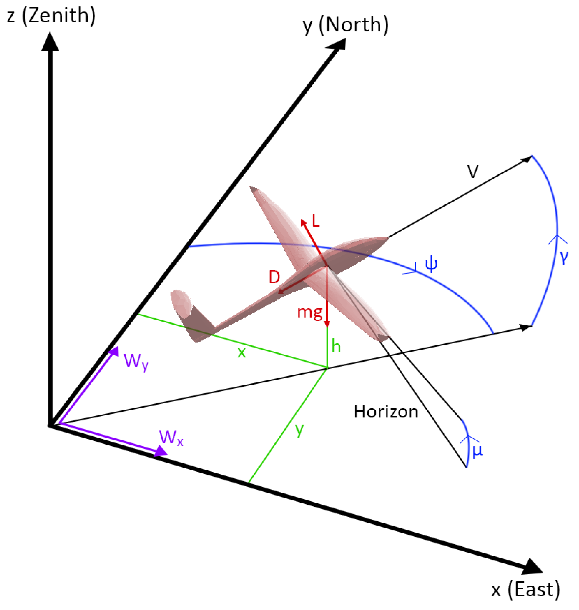
The system dynamics used in this work was based on a three-degree-of-freedom (3DOF) point mass model of an SUAV. The motion of the aircraft is relative to an inertial frame located on the Earth’s surface. Figure 1 depicts a free body diagram of the model, and the equations of motion [5,23], adapted for wind in the x, y, and z directions, are defined as follows, where V is airspeed, g is standard gravity, L is lift, D is drag, m is the aircraft’s mass, ψ is the heading angle, γ is the pitch angle, μ is the roll angle, x, y, and h are the aircraft’s positions in the x, y, and z directions relative to the inertial frame, and  W x , W y , and  W z are the environmental wind strengths along their respective axes:
V ˙ = D m g sin ( γ ) W x ˙ cos ( γ ) sin ( ψ ) W y ˙ cos ( γ ) cos ( ψ ) + W z ˙ sin ( γ )
ψ ˙ = L sin ( μ ) V m cos ( γ ) W x ˙ cos ( ψ ) V cos ( γ ) + W y ˙ sin ( ψ ) V cos ( γ )
γ ˙ = 1 V L cos ( μ ) m g cos ( γ ) + W x ˙ sin ( γ ) sin ( ψ ) + W y ˙ sin ( γ ) cos ( ψ ) + W z ˙ cos ( γ )
To track the aircraft’s states, the kinematic equations of motion are defined, relating the motion of the aircraft with respect to the inertial frame:
x ˙ = V cos ( γ ) sin ( ψ ) + W x
y ˙ = V cos ( γ ) cos ( ψ ) + W y
h ˙ = V sin ( γ ) + W z
Lift and drag are computed as shown below, with local air density ρ , wing reference area S, lift coefficient C L , and drag coefficient C D :
L = 1 2 ρ V 2 S C L
D = 1 2 ρ V 2 S C D
The drag coefficient is a function of both parasitic and lift-induced drag, where C D 0 is the zero-lift drag coefficient, K is the induced drag factor, and E m a x is the maximum lift-to-drag ratio:
C D = C D 0 + K C L 2
K = 1 4 C D 0 E m a x 2
Furthermore, the total energy of the aircraft e T comprises both the kinetic e K and potential e P energies as described:
e T = e K + e P
e K = 1 2 m V 2
e P = m g h
The elements of the state vector shown below were purposefully selected to only include variables that would typically be measurable onboard an SUAV. In addition, the control variables were chosen to be navigation-level commands that can be conveyed to an autopilot system:
x = V ψ γ h h ˙ , u = C L μ
This mathematical model of the aircraft is required for trajectory optimization and, more generally, can be used to simulate a physical system. However, soaring techniques rely on naturally occurring winds, which must also be expressed through models.

2.3. Dynamic Soaring

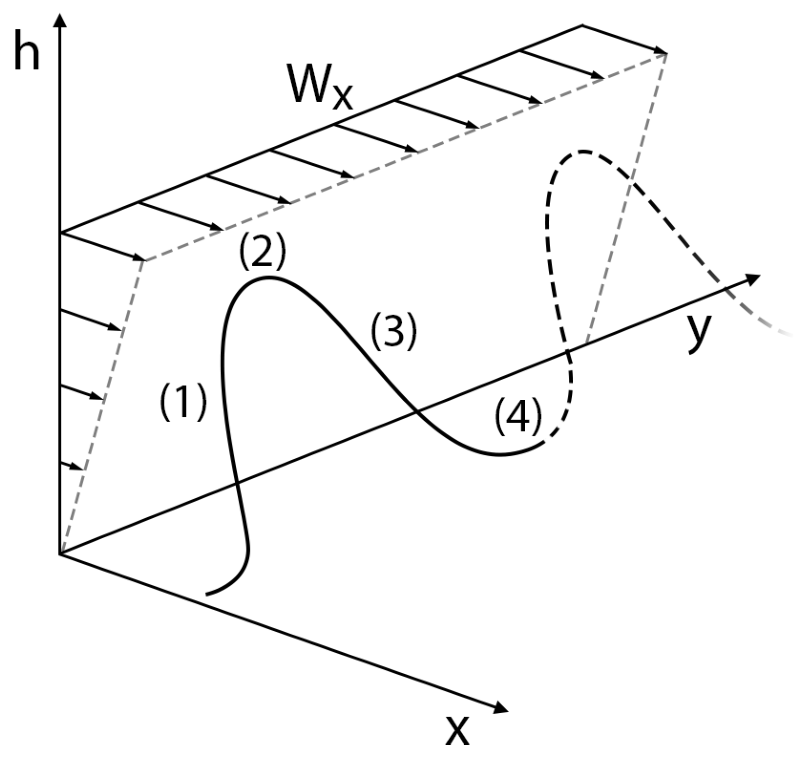
A traveling dynamic soaring cycle, illustrated in Figure 2, can be characterized by five primary segments: upwind climb (1), high altitude turn (2), downward sink (3), low altitude turn (4), and an intermediary traveling component for expending any additional energy gained over the cycle [1]. An agent undergoing dynamic soaring trades kinetic energy for potential energy as it gains altitude by turning upwards into the wind field and subsequently trades the potential energy for kinetic energy after it turns downwards away from the wind. This cycle repeats as the agent travels in a specific direction over soaring cycles.
From the initial formulation by Zhao [5], the horizontal wind profile from which energy is extracted can be modeled through a horizontal wind speed W x , represented by a shape parameter A x , an average gradient slope β x , a maximum wind speed W m a x y , and a transitional altitude h t r x :
W x = β A h + 1 A x h t r x h 2 h < h t r x W m a x x h h t r x
β = W m a x x h t r x
The rate of change of the wind profile is defined as:
W x ˙ = β x A x + 2 1 A x h t r x h V sin ( γ )
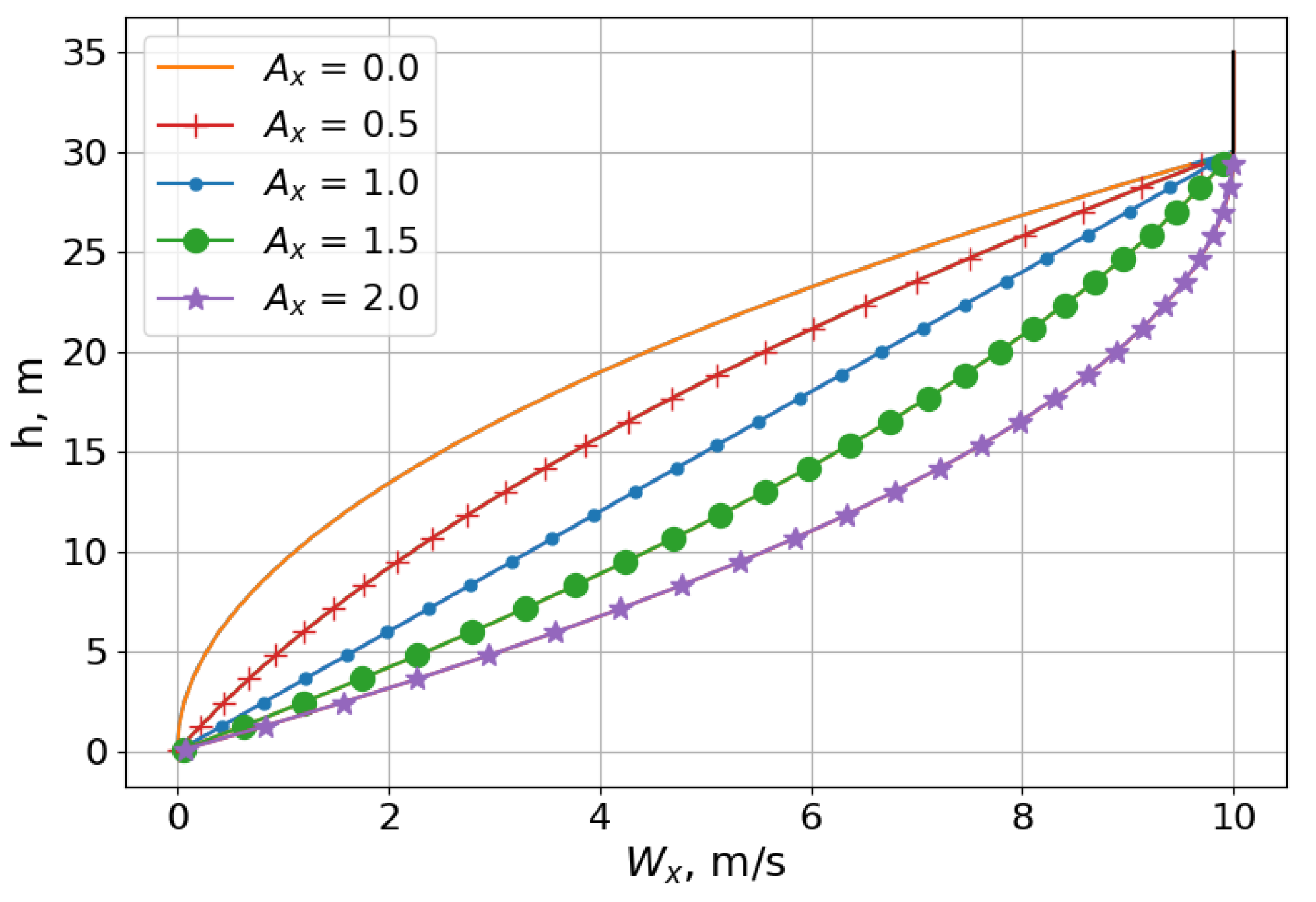
Figure 3 shows that this model represents a logarithmic wind profile when 0 < A x < 1 and an exponential profile when 1 < A x < 2 . Furthermore, for  W x to not exceed W m a x x , A x must be limited to [ 0 , 2 ] , with a shape value A x = 1 corresponding to a linear profile. An identical model can be used to simulate wind W y in the y direction.
In the trajectory optimization framework, the boundary constraints for dynamic soaring would include initial and final conditions on the airspeed, heading angle, pitch angle, and coordinate states. For the traveling case, the latter would not be subjected to final conditions, as the distance covered would be a variable result of the optimized trajectory output.
V ( 0 ) = V 0 V ( t f ) = V f ψ ( 0 ) = ψ 0 ψ ( t f ) = ψ f γ ( 0 ) = γ 0 γ ( t f ) = γ f x ( 0 ) = x 0 y ( 0 ) = y 0 h ( 0 ) = h 0

2.4. Thermal Soaring

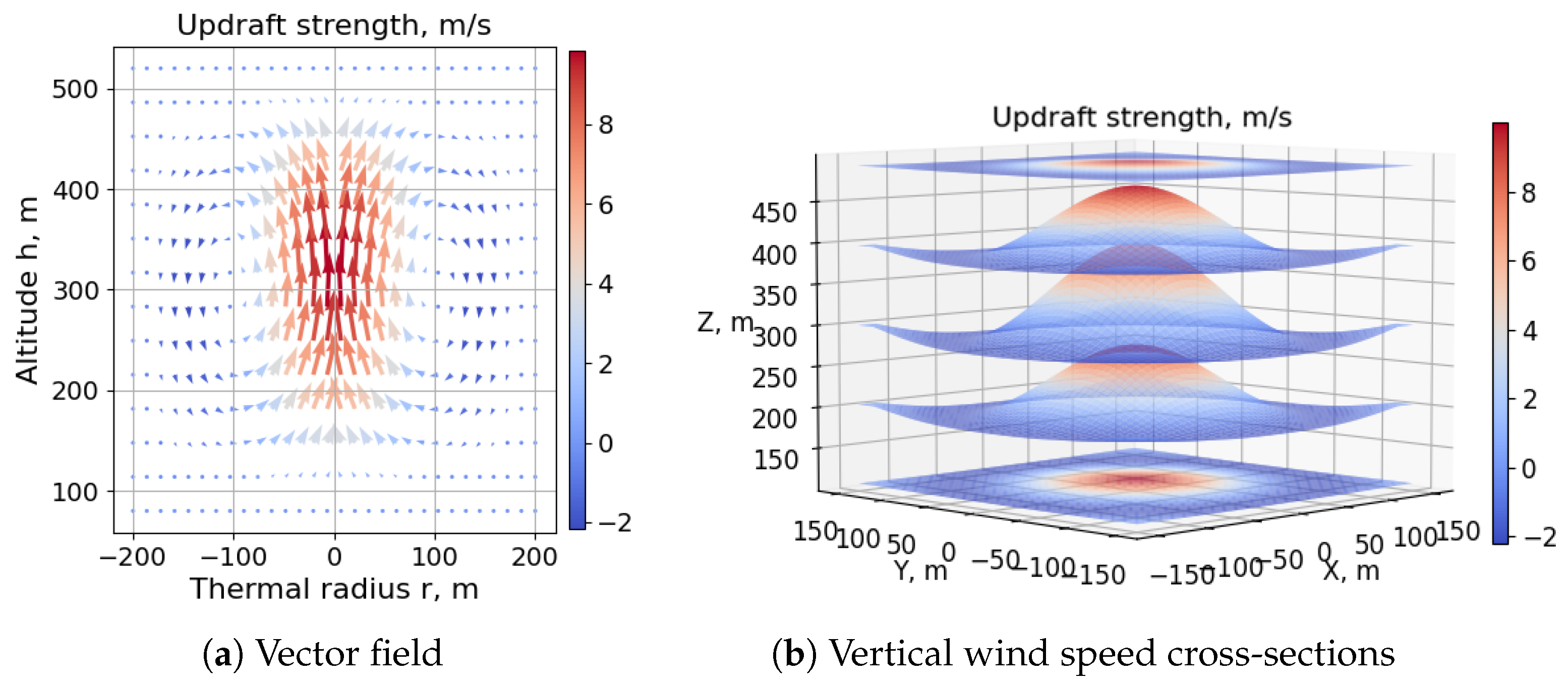
In thermal soaring, a flight agent circles around a region containing an updraft to gain altitude before eventually exchanging the potential energy for kinetic energy by soaring out of the thermal once the updraft fades. A common model for thermals is the toroidal bubble model described by Lawrance and Sukkarieh [24], which is characterized by a core updraft region surrounded by sinking air, disconnected from the ground and moving upwards over time. This representation is visualized in Figure 4.
The model, minimally altered from the original formulation to fit the coordinate system presented in Section 2.2, is defined by the agent’s distance from the thermal center r, the maximum core updraft wind speed W c o r e , the thermal’s height h t , the thermal radius over the x y plane r x y , the radius over the z axis r z , the bubble eccentricity factor k, and the rising velocity h t ˙ , where x, y, and h are the agent’s location in the inertial frame:
r = x 2 + y 2 , k = r z r x y
W z = w c o r e r = 0 , h [ h t r z , h t + r z ] cos ( 2 π 4 r z ( h h t ) ) r x y w c o r e π r sin ( π r r x y ) r ( 0 , 2 r x y ] , h [ h t r z , h t + r z ]
W x = W z h h t ( r r x y ) k 2 x r
W y = W z h h t ( r r x y ) k 2 y r
The rates of change of the wind components were calculated using the finite difference approximation method for simplicity. In this model, the bubble rises from an initial height h t 0 at a speed h t ˙ , which allows a flight agent to continually gain potential energy as long as the thermal remains sufficiently strong. In all, these models of the flight agent and wind conditions were used to simulate an environment in which controllers were trained and soaring tests conducted.

3. Neurocontrol

This section describes the neural-network-based evolutionary control scheme by explaining the motivation for its use, providing a description of the main algorithm and detailing the specific parameters and functions used for this work.

3.1. Neural Network Topology

Although classic trajectory optimization techniques provide numerically optimal solutions, recent advancements in neural network research have encouraged the exploration of artificial-intelligence-based approaches in generating soaring trajectories in a more general, behavior-like manner that can be executed on the limited computing hardware onboard SUAVs. For instance, the field of dynamic soaring has already seen the application [12,13,14,15] of one of the most common disciplines of artificial intelligence, known as reinforcement learning. In such approaches, neurocontrollers are trained to behave in a particular manner or to follow a policy π by constructing a mapping of states S to actions A:
π : S A
For complex, nonlinear systems, this process often involves the use of neural networks as function approximators that estimate the value V of taking a specific action from a particular state. As a learning agent interacts with the environment either directly or through a simulation, it receives rewards R that encourage or discourage certain actions, based on a defined evaluation criterion J. For autonomous soaring, the costly nature of learning through trial and error necessitates a simulation-based training approach. Furthermore, control actions that result in an energy-neutral trajectory can only be evaluated after a full soaring cycle, and as such, the optimal policy π * can be defined as the mapping between states x ( t ) and actions u ( t ) that maximizes this energy-based performance criteria, or achieves the greatest reward:
π * : x ( t ) u ( t )
Often, this policy is either indirectly encoded through stochastic exploratory and exploitative mechanisms or more consistently and directly defined in the form of a neural network as is the case for more complex RL algorithms. In this way, different learning algorithms can be applied to the soaring problem to obtain neural-network-based control strategies, where inputs such as aircraft states can be fed-forward to obtain the control action that will maximize the reward.
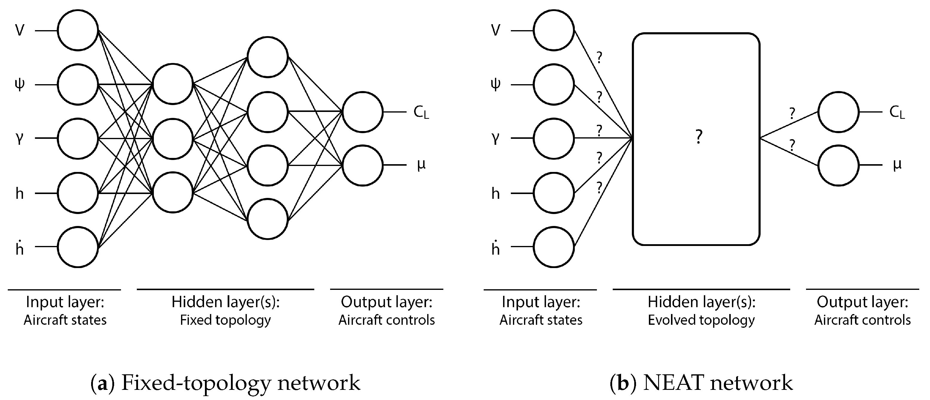
However, to avoid the structural limitations of fixed-topology networks and the consequent omission of a subset of potential solutions, NEAT can be used to evolve unique networks that are optimized in node and connection weights, as well as in topology. This difference is illustrated in Figure 5.
Canonical tests in solving artificial intelligence and control problems have demonstrated the NEAT algorithm’s ability to generate networks that often perform better while being much simpler than fixed-topology networks [19].

3.2. Neuroevolutionary Strategy

The NEAT algorithm operates on the principle of Darwinian fitness, which is a measure of how well an individual is able to propagate itself through successive generations. In the context of this study, the fitness of a neurocontroller is the value that defines how well a neural network is able to perform autonomous soaring in a virtual environment, which in turn directly influences its survivability in the evolutionary process.
Initially, the algorithm populates a generation with random members, or neurocontrollers, with randomly generated features. These features, consisting of the unique topology and weights of a member, are encoded within its genotype, a data structure that contains information about each node and connection, the value of each node and connection, and the point in the evolutionary process at which each node and connection was created. In addition, members that share similar network shapes are grouped together into subcategories classified as species, which is a protective structure that allows for the optimizing of the node and connection weights. For instance, it is highly unlikely that a random mutation that results in a new connection would immediately increase a member’s fitness, since the weight associated with the connection would not have yet undergone tuning, or the optimization process. By only comparing a member against other members within its own species through this mechanism, known as speciation, innovative mutations have a chance to mature. Nonetheless, each genotype completely characterizes a unique neurocontroller, and this particular neural network encoding method allows for the tracking and evolution of network topologies.
After every member of a new population is evaluated in a virtual test environment and assigned a fitness value, species undergo reproduction by eliminating the members with the lowest fitnesses before creating offspring and undergoing mutation. Offspring arise when two genotypes, or parent networks, are spliced and concatenated in a process known as crossover at randomly determined points along each genotype, with any genes that do not undergo crossover being inherited from the parent with the higher fitness value. This process allows for two neurocontrollers to merge and create a better-performing network. Once offspring are generated, mutations have a chance to occur. Mutation processes encompass various different operations, including the random addition and subtraction of nodes and connections, all of which are made possible by the gene history encoded in each genotype. The crossover and mutation operations allow for the creation of new, unique neural networks while persevering the genes or characteristics that contribute to high fitnesses. Lastly, competition between species is addressed through stagnation, which is when the highest fitness achieved by a member of a species has not improved after a certain number of generations. Such species are marked as stagnant and are prohibited from reproducing further, eventually becoming extinct through the generational culling process. However, to prevent the complete extinction of all species, an elitism mechanism preserves a small number of the highest-performing species, regardless of whether they have stagnated.
This entire process is managed by the NEAT algorithm, which populates each generation, evaluates every member once, and outputs the best-performing neural network after a fitness threshold is reached or a certain number of generations has elapsed. The evolutionary algorithm is depicted in the outer loop of Figure 6, the entirety of which presents the main effort of this work. The inner loop tests each member of the generation one at a time in a simulation environment that includes a model of the flight agent and wind profile. At every time interval of the assessment, the neural network being evaluated receives aircraft states to produce control outputs used to propagate the simulation and obtain the flight agent’s subsequent states.
At the end of each test, an evaluation process examines the trajectory along which the neural network controlled the flight agent to determine the member’s fitness score. For the test cases presented in the following sections, this value was the numerical output of a specifically designed function that included penalties proportional to the degree to which the neurocontroller exceeded flight constraints, as well as rewards dependent on the total distance that the flight agent traveled. The NEAT algorithm then receives and stores the fitness of each member until every member of the population is evaluated, before creating new members and extinguishing unsuccessful networks. In this way, the presented procedure progressively creates better-performing neurocontrollers.

3.3. Neuroevolutionary Implementation

The fitness function that was used to evaluate the performance of each network during the evolutionary cycles is a critical design element that has a significant influence on the network behavior. The functions used for the dynamic and thermal soaring test cases presented in the next section were similar in that they both included penalties that discouraged the flight agent from exceeding trajectory constraints. Since the evaluation process occurs after a member completes a flight episode in the simulation environment, the histories of the states and controls experienced during the simulation were examined for any values that surpassed limits. These included the following variables:
Airspeed : Height : Pitch angle : Load factor : Pitch rate of change : Heading rate of change : Lift coefficient rate of change : Roll rate of change : V m i n V V m a x h m i n h h m a x γ m i n γ γ m a x n n m a x γ ˙ m i n γ ˙ γ ˙ m a x ψ ˙ m i n ψ ˙ ψ ˙ m a x C L ˙ m i n C L ˙ C L ˙ m a x μ ˙ m i n μ ˙ μ ˙ m a x
The penalties for each of these trajectory variables were calculated as the sum of the value by which the limits were exceeded over every time step t of the simulation. This formulation accumulated penalties proportional to how severely a limit was surpassed. The scheme is expressed below, where x h i s t o r y is the array of values collected over the duration of the simulation, which lasted from t 0 = 0 to t f :
x p e n a l t y = t = 0 t f m a x ( 0 , x h i s t o r y ( t ) x m a x ) + m a x ( 0 , x m i n x h i s t o r y ( t ) )
The penalties of all variables x p e n a l t y = x p e n were then squared, summed, and negated to result in a single value that became the fitness f of a member π :
f π = ( V p e n 2 + h p e n 2 + γ p e n 2 + n p e n 2 + γ ˙ p e n 2 + ψ ˙ p e n 2 + C L ˙ p e n 2 + μ ˙ p e n 2 )
For the traveling dynamic soaring case, however, a reward mechanism was necessary to incentivize the neurocontroller to steer the flight agent along a direction. The reward r π was equal to the square of the agent’s displacement along the x y plane:
r π = ( x f x i ) 2 + ( y f y i ) 2
In the case of a reward, the overall fitness function was a linear combination of the reward and penalty values, where k 1 and k 2 were experimentally tuned constants that prevented either value from dwarfing the other:
f π = ( k 1 × r e w a r d ) ( k 2 × p e n a l t y )
In addition, to strongly dissuade neural networks from exceeding system-critical constraints, an extremely large penalty was attributed to members who steered the model into the ground, induced excessive load factors, or stalled the model.

3.4. Simulation Environment

An explicit time simulation environment was used to train the neurocontrollers presented in the following section. Using the equations of motion for the flight agent along with the wind models described in Section 2, the simulation time was incremented by a discrete time step δ > 0 , and future state values were computed through a first-order approximation. The forward Euler method used to advance the simulation is detailed below, where a state x k at time step k is updated to x k + 1 :
x k + 1 = x k + δ x k ˙
A neurocontroller undergoing evolution influences the states of the flight agent through the control commands that it outputs, consequently dictating its own trajectory. Throughout the simulation, the state and control histories are recorded so that once the simulation terminates either due to the member crashing the flight agent or exhibiting sustained flight for the maximum simulation duration, the member’s fitness score can be evaluated from the complete trajectory. Therefore, the dynamics function advancing the simulation was programmed separately from the fitness function called at the end of a simulation, which by extension is where path constraint checks and penalties were also calculated. The simulation is summarized by Algorithm 1.
Algorithm 1 Flight simulation.
 1: for neural network π N in population Π  do
 2:   while  t < t f  do
 3:     statesget_states()▹ fetch aircraft states
 4:     if  s t a t e s > c o n s t r a i n t s  then
 5:     break
 6:     actions π N (states)▹ obtain control commands
 7:      W x , W y , W z get_wind()▹ calculate local wind profile
 8:      x k + 1 x k + δ x k ˙ ▹ apply dynamics model
 9:      t + = δ
10:    f π get_fitness()▹ compute rewards and penalties
Each run of the evolutionary neurocontrol optimization presented in this paper consisted of a population size of 250 members, repeated over 100 generations. To accelerate the process of testing neural networks in the simulated flight environment, the 250 simulations conducted at every generation were run in parallel, with each simulation ending after a maximum simulation time of 600 s. Overall, the simulation environment was integrated into a NEAT implementation matching the original NEAT formulation that was ported into Python. As the fitness of each neural network was evaluated, a new instance of the simulation environment was initialized, which stepped through discrete time intervals until the neurocontroller either failed or succeeded at exhibiting feasible soaring patterns.

4. Results and Discussion

The following autonomous soaring test cases show the evolutionary approach’s capacity to generate simple and effective neurocontrollers. In the first case, a controller was evolved in a bidirectional wind environment using a biological albatross model to compare the trajectory of the neurocontroller to that of an albatross bird. The second case shows a neurocontroller evolved using a typical commercial SUAV model to demonstrate the NEAT-based training approach’s applicability to aerial vehicles, and the third test case presents an instance of SUAV thermal soaring. As was shown in Section 2.1, the state vector used as inputs to the evolving neural networks does not contain any explicit information on the local wind field, and as such, the following neurocontrollers evolved by interacting with the wind model without prior knowledge of the environmental conditions. Similarly, the networks also did not receive the simulation time, indicating that the following results did not arise from a generated schedule of control commands.
Although the length of the simulations can vary greatly between population members due to the inherently unique nature of neurocontroller species, the neural networks shown in the next section required an average CPU time of 0.224 min across all three test cases to evolve a successfully soaring neurocontroller. For reference, the entire evolutionary process was run on an Intel four-core CPU with 16 GB of memory.

4.1. Albatross Dynamic Soaring

The characteristics of the albatross model [1] are shown in Table 1. The parameters of both the flight agent and the wind were selected to compare the results against the data collected and presented by Sachs et al., who recorded the energy extraction cycles of wandering albatrosses through GPS signal tracking [3]. Parameters with the subscript 0 represent initial conditions at time t 0 = 0 .
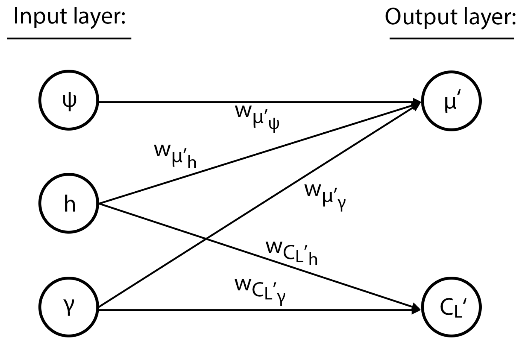
The neurocontroller that was trained using the albatross flight model with a two-dimensional wind profile described in Section 2.3 is shown in Figure 7. Evolved with both the distance-based reward and penalty functions detailed in Section 3.3, the neural network uses a reduced input space of three nodes and no hidden layers, defined only by direct connections to the output nodes.
The bias nodes b C L and b μ , as well as the connection weights w take the values:
b C L = 2.86 w μ ψ = 1.96 b μ = 1.37 w μ h = 0.0759 w μ γ = 2.16 w C L h = 1.73 w C L γ = 1.62
Mathematically, the feedforward network can be described as shown below, where Equation (47) converts the normalized outputs C L and μ of the sigmoid function σ ( x ) to values within the aircraft control limits:
C L = σ ( w C L h ˙ h ˙ + w C L γ γ + w C L V V + b C L )
μ = σ ( w μ h h + b μ )
σ ( x ) = 1 1 + e x
C L μ = C L 0 0 μ C L m a x C L m i n 2 μ m a x + C L m i n μ m a x
The simplicity of the neural network revealed that the roll angle was determined by the agent’s height, with the lift coefficient determined by the height rate of change, the pitch angle, and the airspeed. This interpretability is important for the implementation and adoption of neurocontrol systems, where understanding the internal mechanisms of networks is a significant component in building trust in such systems. This characteristic of the neuroevolutionary method is further examined in the next test case.
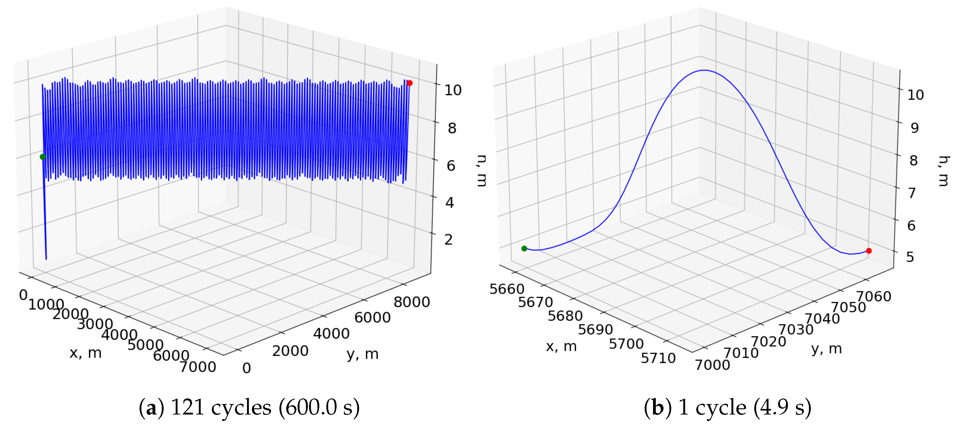
Figure 8a shows the resulting trajectory of simulating this neurocontroller for 600 s in the bidirectional wind environment, and Figure 8b shows a single period of the same trajectory after the aircraft reaches a stable pattern. The flight agent undergoes an initial transitional period before it reaches an equilibrium point conducive to sustained cyclical soaring.
The smooth states of a consecutive five-cycle segment, shown in Figure 9, mimic the soaring trajectories of albatross birds [3]. Furthermore, examination of the maximum total energies of the five cycles reveals that the aircraft experiences positive net changes in energy between some periods and negative net changes for others, with this pattern of gaining and losing excess energy continuing throughout the test. Constantly accumulating additional energy between cycles is both naturally limited by the finite wind gradient and undesirable when maintaining stable soaring cycles. Therefore, sustained dynamic soaring is a problem of ensuring that the total energy of the agent does not fall below a certain threshold under which the ability to extract sufficient energy for future cycles is compromised. The test trajectories showed that the neurocontroller can manage the agent’s energy for continuous dynamic soaring, balancing any losses in energy with gains in subsequent cycles. This ability to generate continuous and stable soaring cycles after simple feedforward passes through a sparse neural network contrasts the much more limited trajectory horizons of numerical optimization, which typically only plots trajectories of a single period after extensive computation. By ensuring that the fitness criteria in the genetic algorithm are in part a function of the time for which a particular species survives, the proposed method evolves sustainable soaring as a trait within the controller itself.
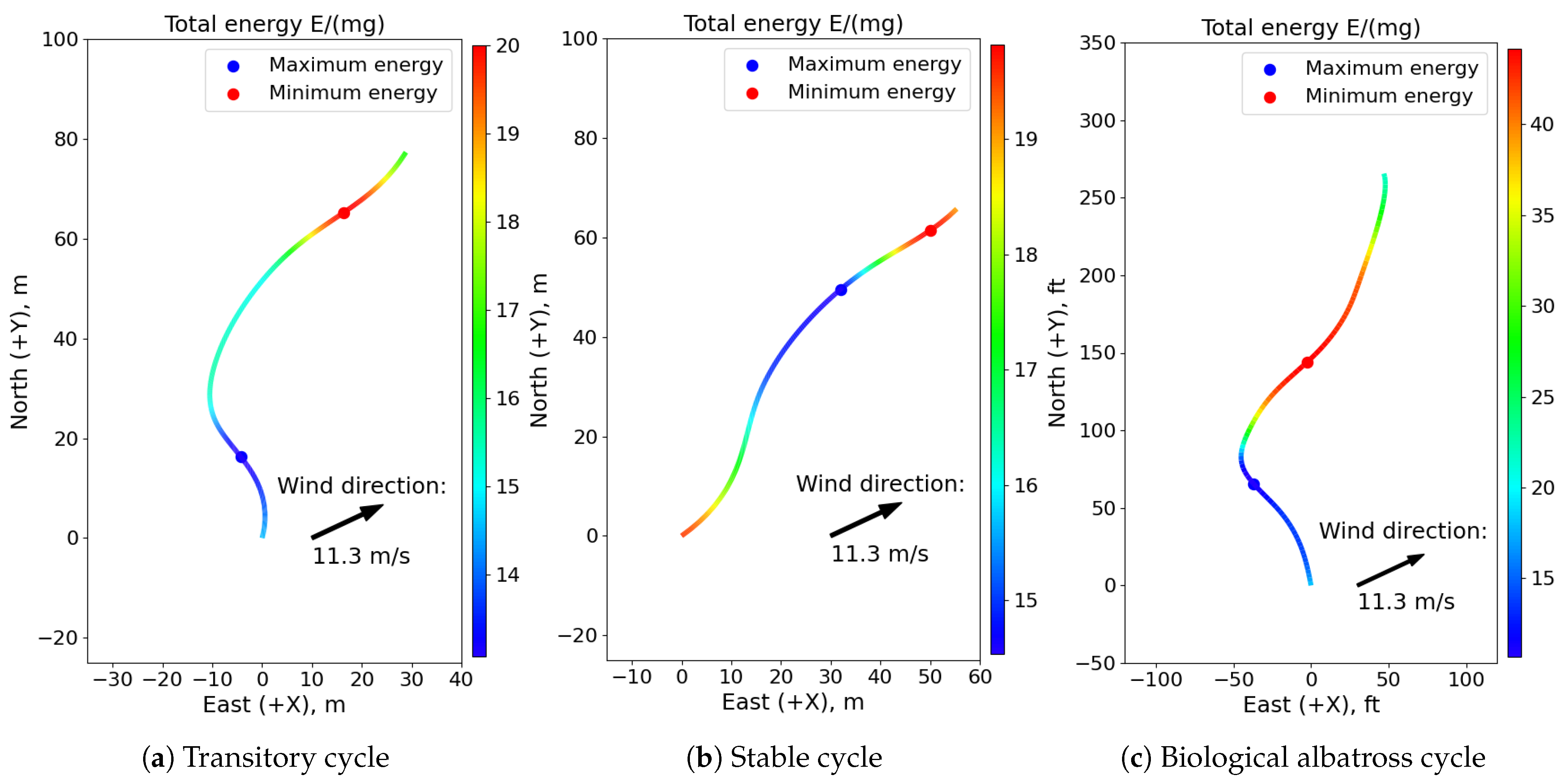
The differences in the total energy histories in the initial transitional phase of the soaring test, its stable phase, and a recorded cycle of a biological albatross flight captured by Sachs et al. [3] are illustrated in Figure 10, presented as specific energies. For the transitional cycle, the point of minimum energy occurs during the upwind climb phase as the flight agent uses the wind gradient to accumulate sufficient energy for sustained soaring. After increasing its total energy over multiple transitional cycles, the agent eventually reaches the altitude limit of the gradient and achieves a maximum airspeed that does not exceed control and structural limits. In the stable cycles, the minimum total energy point exists immediately before the downward sink, showing that the aircraft expends most of its energy during the upwind climb and high altitude turn phases before rapidly accelerating into the dive maneuver. This sharp fluctuation between extremes leaves little time to accumulate additional energy, which is necessary to prevent the agent from soaring out of the wind gradient layer or exceeding aircraft limits.
The recorded albatross flight resembles the transitory cycle of the neurocontroller better than the stable period, showing a stronger turn into the wind during the upwind climb phase to accrue excess energy. This aggressive maneuver from the albatross may have been necessary in the presence of a varying and uneven wind profile, unlike the deterministic wind experienced by the neurocontroller. In addition, a flying albatross is likely motivated by much more complex objectives such as minimizing control effort, maximizing flight time, and pursuing prey that extend beyond the relatively simple distance maximization criterion of the neurocontroller. Regardless, the trajectories of the neurocontroller show the smooth, continuous flight that is characteristic of albatross birds undergoing dynamic soaring. Discrepancies between flight paths can be attributed to the simulation’s unique wind modeling parameters and the inherently more complex behaviors of biological organisms.

4.2. SUAV Dynamic Soaring

Another neurocontroller was evolved using an SUAV model for the flight agent and a different set of wind parameters, all of which are described in Table 2. The resulting neural network of Figure 11 was evolved in a unidirectional wind environment and also only defined by input and output layers much the same as the albatross network, relying solely on the heading and pitch angles.
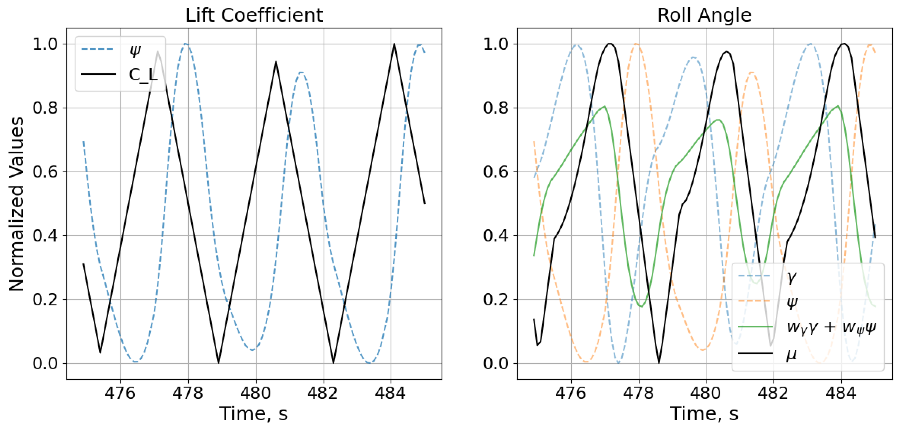
However, the topology of this neurocontroller is even more sparse than that of the albatross network. This reduction in network complexity can be attributed to the unidirectional wind profile of the environment in which the SUAV controller was evolved. There is simply one less dimension that the network must account for, and since the network must infer the wind model through its effects on the aircraft without receiving measurements of the local wind, this reduction of the wind profile has a nontrivial impact on the resulting topology. Nevertheless, the simplicity of the network further enables its interpretation. The network is rolling based on the aircraft’s pitch and heading angles while determining the angle of attack based on where the aircraft is headed. The NEAT process indirectly encoded the characteristics of the wind profile that the neurocontroller was subjected to during evolution into the neural network’s topology and weights, and this knowledge of the environment was used to determine when to execute pitch and roll maneuvers that led to dynamic soaring trajectories. To further illustrate the close relation between the states and controls, Figure 12 shows the input signals plotted against the output control commands. Even without the effect of the sigmoid function and the subsequent scaling of the normalized controls, the outputs can be seen to track their respective inputs, albeit with offsets that are simply the result of the specific connection weights and biases. The proximity of the network’s inputs to its outputs in terms of the number of intermediary nodes and connections enables the observing and analytical tracking of the network’s feedforward process, and this topological traceability allows for a precise, intuitive understanding of the neurocontroller. This interpretability is an important aspect for validating neurocontrol schemes that is difficult to achieve with the abstract, black-box nature of densely interconnected deep neural networks.
Figure 13 shows the trajectories of different scales as a result of simulating this neurocontroller in a unidirectional wind environment. The plots show that the SUAV model achieved a stable pattern near the transition height of the wind profile, which was uniquely shaped in this test case. The altitudes at which the aircraft would soar were too high to use the wind profile detailed in Section 2.3, since the vertical gradient would be insufficiently weak when stretched over hundreds of meters. Therefore, the model used for this test case compressed the profile into a much smaller altitude range, as shown in Figure 14, allowing the lightweight SUAV to extract enough energy from the environment. To perform dynamic soaring with greater altitude fluctuations and longer soaring cycles, a stronger wind profile would be required, with a proportionately sufficient vertical wind gradient, as well as a more robust aircraft that can withstand the load factors associated with more strenuous flight maneuvers. Regardless, the trajectories exemplify the ability to evolve neurocontrollers for dynamic soaring trajectories at altitudes much higher than those experienced by soaring seabirds, with narrower wind gradients.
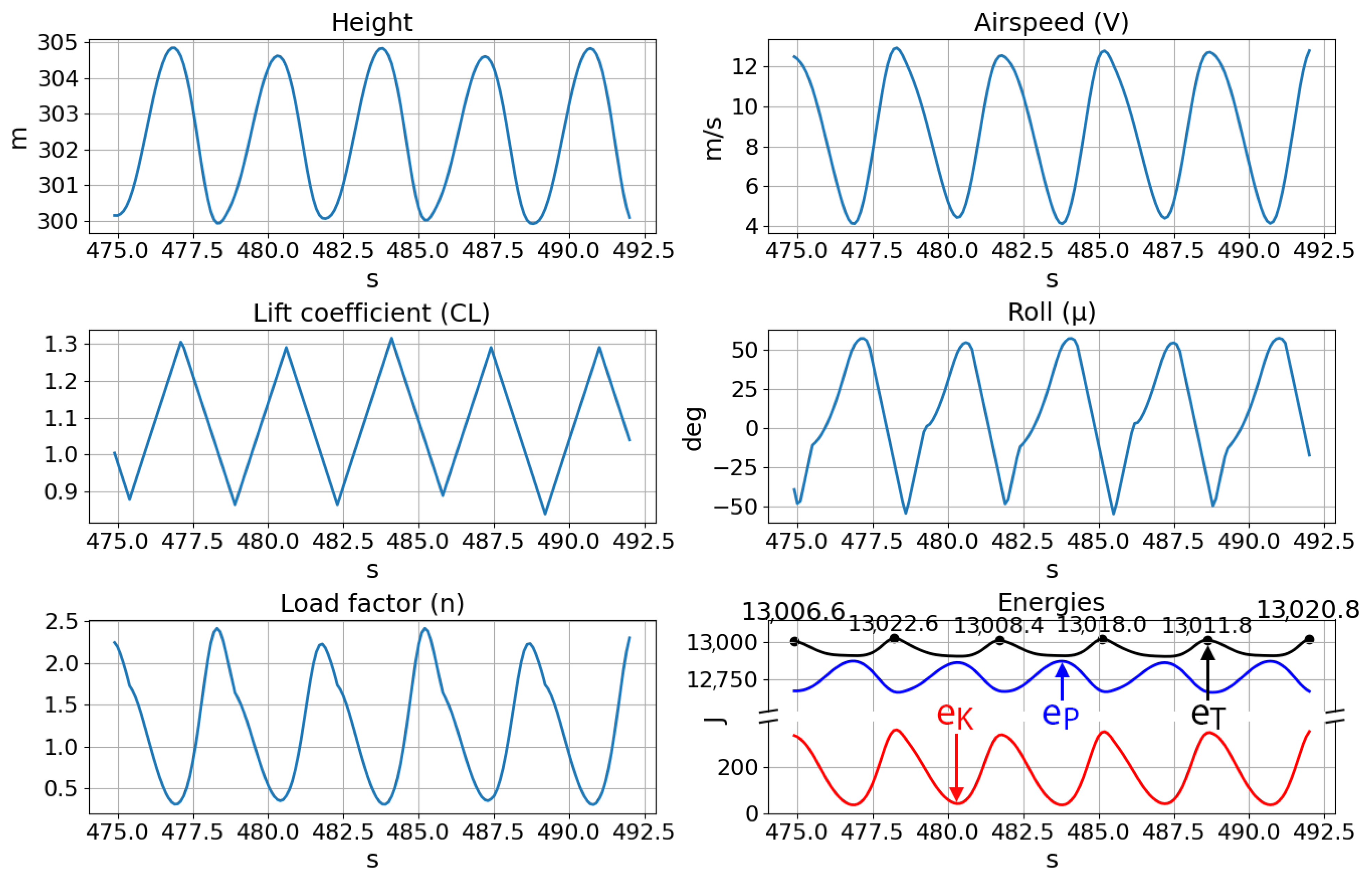
The smooth states of the multiperiod trajectory, shown in Figure 15, are desired when considering the response rates and limitations of real control systems and physical vehicles. The relatively abrupt changes in the lift coefficient and roll angle controls, however, are required for the rapid maneuvers of dynamic soaring, a characteristic that is also reflected by the cyclic history of the load factor. Additionally, the energy histories do not contain any significant reduction in the total energy between cycles, demonstrating that the neurocontroller can continuously soar given a constant wind profile. In reality, the finite nature of environmental winds would pose a greater obstacle to indefinite soaring than any periodic reduction in energy.
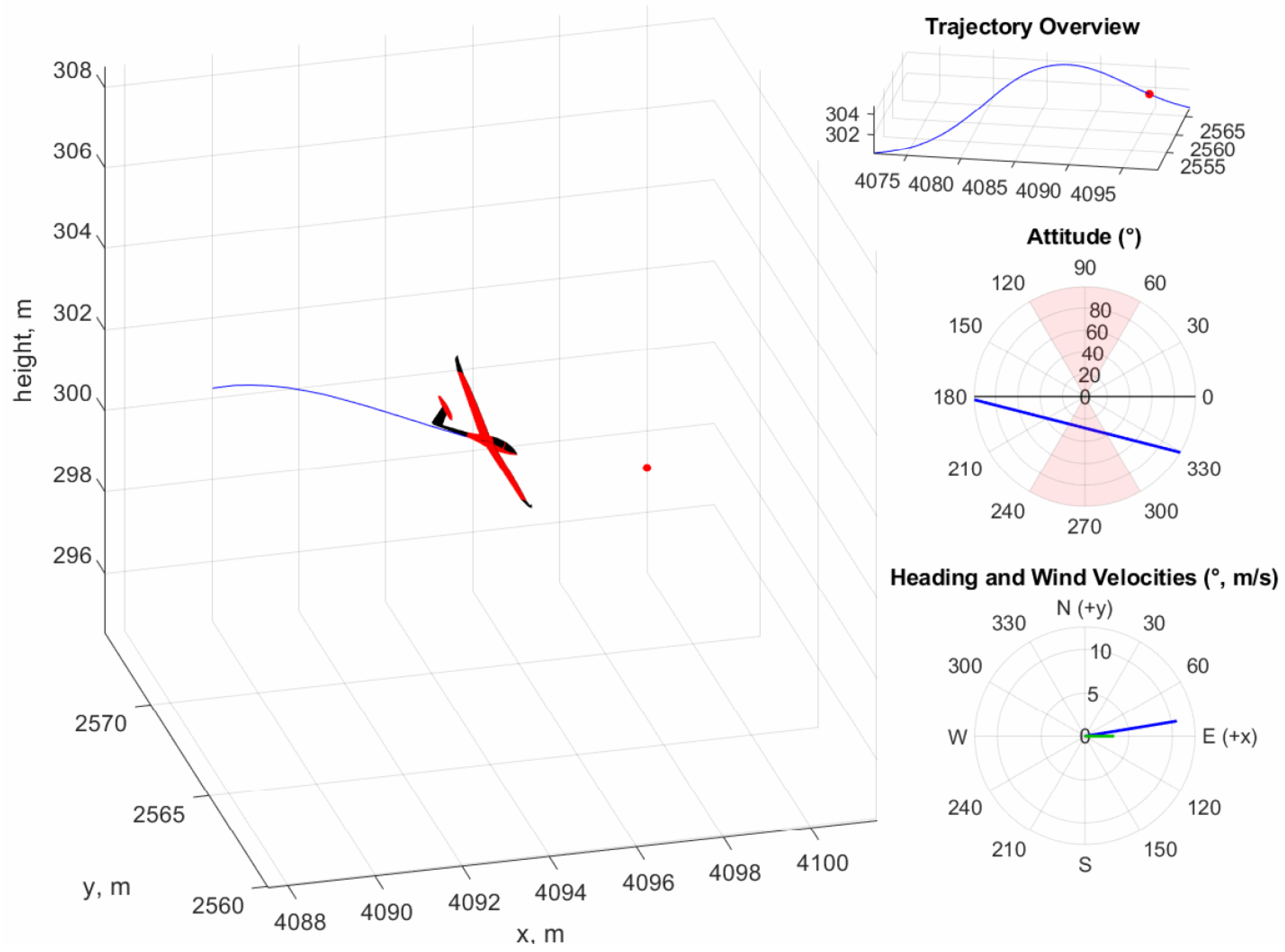
Figure 16 provides a dynamic visualization of the aircraft as it soars through a cycle of the trajectory. The observation of dynamic soaring behavior from such a simple neural network highlights the advantages of the neuroevolutionary method, which are that such controllers are more easily implementable on hardware-limited SUAV platforms than more complex neural networks while being interpretable.
To compare different trajectory planning and control approaches, a numerical trajectory optimization was performed for a single soaring cycle through a direct trapezoidal collocation nonlinear programming approach as described in Section 2.1, where the optimization was conducted with pyOPT using the SNOPT optimizer [25]. The SUAV and wind models were identical to those described in Table 2, and the boundary and path constraints are detailed in Table 3, with the initial and final conditions based on the neurocontroller trajectory of Figure 13b. The trajectory optimization also used the cost function shown in Equation (41) to maximize the total distance traveled over the soaring cycle.
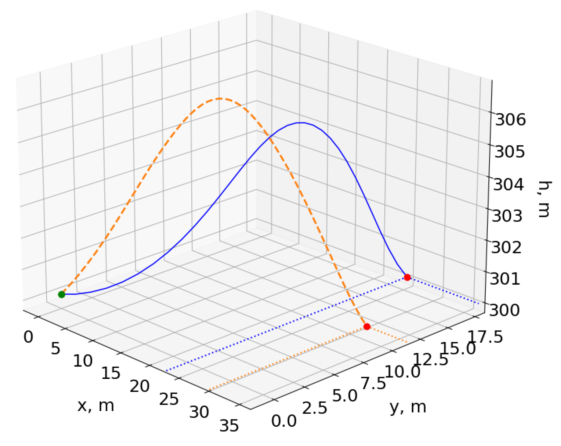
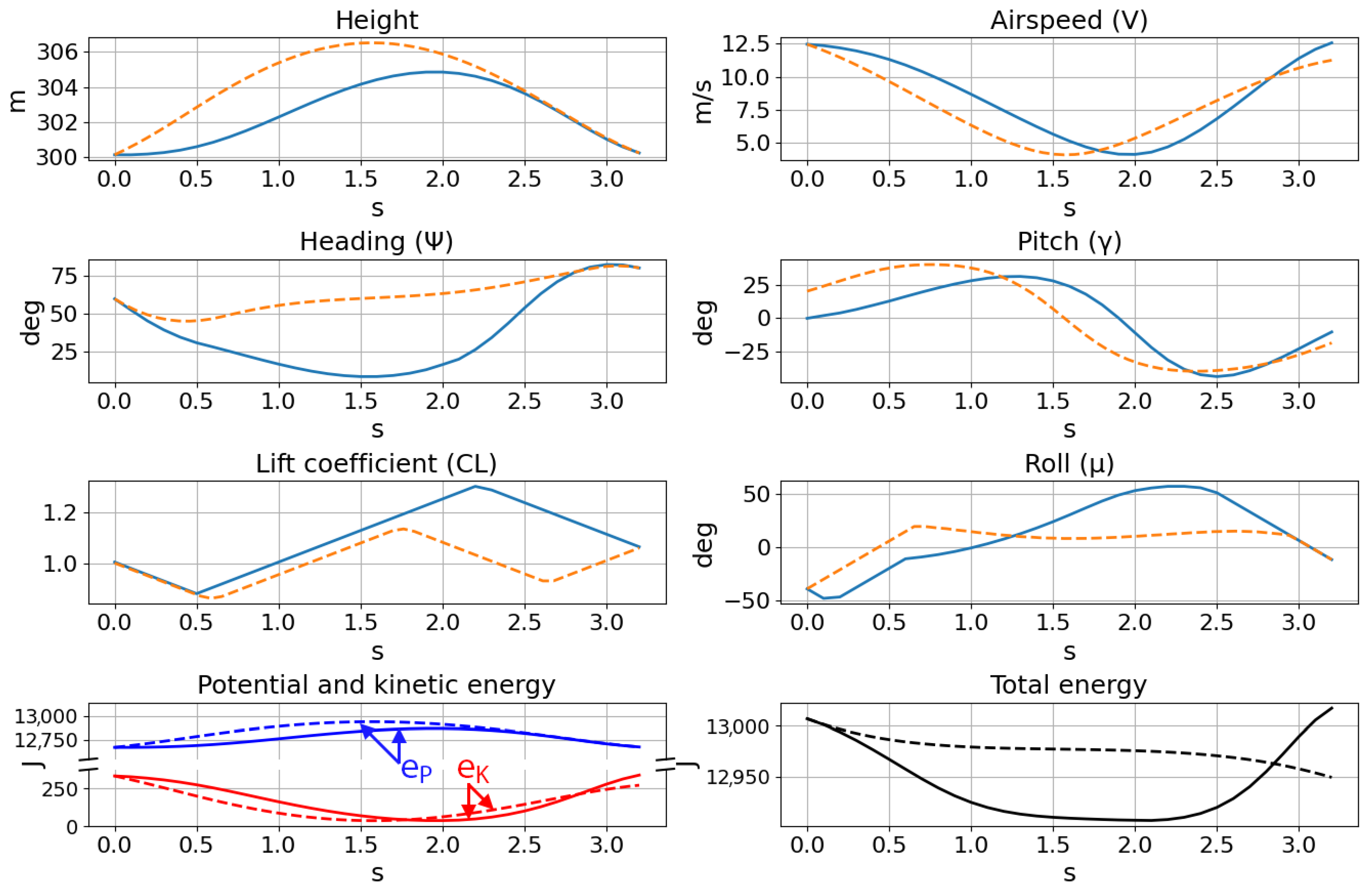
The optimization process, consisting of 50 collocation points, took a CPU time of 1.55 min, nearly seven-times longer than the entire evolutionary process that produced the SUAV neurocontroller of Figure 11, which once trained, procedurally generates trajectories in real time. Furthermore, although the flight paths and traces of the two methods superimposed for comparison in Figure 17 and Figure 18 show similar trajectories, the energy histories indicate that the optimized flight path ultimately cannot be used for dynamic soaring. While the boundary conditions were satisfied, the optimization process does not take into account the practical requirement for repeatable trajectories when computing individual cycles at a time. The singular focus on the cost function precludes any consideration of sustainable soaring, resulting in the decrease in the total energy after a single cycle. Attempting to calculate a longer trajectory comprised of multiple soaring cycles is also significantly more costly in terms of computation time and resources, and optimizations performed with twice the number of collocation points yielded identical results.
Many nonlinear programming solvers require an initial guess for the trajectory solution. Consequently, trajectory optimization results are directly dependent on this initial solution provided to the optimizer, and therefore, the computed optimal trajectories are local solutions by nature. In contrast, NEAT allows for the emergence of more global results, since the random member initialization and speciation mechanisms enable the exploration of numerous different network structures and weights, expanding the search space of potential trajectory and control solutions.
Another consideration of using pre-optimized trajectories is that they are decoupled from the control scheme. Either a control framework must be designed around the limits of the trajectory optimization method, or the optimization method must take into account the tracking control scheme prior to the lengthy computation. On the contrary, the presented neurocontroller scheme combines both trajectory planning and aircraft control by imposing and enforcing physical constraints during the evolutionary process. The control outputs and resulting flight path are direct reactions to the state of the aircraft and its environment, reducing the complexity of an autonomous system from a multilayered planning and control approach to one that combines both aspects of soaring. These considerations make it difficult to directly apply numerical trajectory optimization to soaring problems.
The relative simplicity of the NEAT-based neurocontrollers presented in this section becomes further apparent when comparing their topologies to those of related neural networks. For instance, a recent work involving deep neural networks for dynamic soaring control trained three separate neurocontrollers for the angle of attack, bank angle, and wing morphing parameter, each of which consisted of 5 network layers of 16 nodes with 1201 network weight values [12]. Along with the extensive dataset of 1000 optimal trajectories that was required for training, such neurocontrollers make interpretation and implementation on physical systems a significant challenge.
Another work by Li and Langelaan introduced a parameterized trajectory planning method that aimed to solve the lengthy computation times of numerical trajectory optimization [26]. The deep neural network resulting from the actor–critic reinforcement learning method used to generalize the parameterization approach consisted of an actor and critic network, both of which were comprised of two fully interconnected layers, each with sixteen neurons. Considering that the decision-making actor network was solving only for parameters that represent a dynamic soaring trajectory and not the control commands themselves, the relative complexity of the neural network contrasts the simple yet effective NEAT-based neurocontrollers. These related works in the field of dynamic soaring showcase the typical complexities of deep neural networks and highlight the training and implementation advantages of the evolutionary neurocontrol approach.

4.3. SUAV Thermal Soaring

Table 4 details the parameters used to evolve and test the thermal soaring neurocontroller of Figure 19. The horizontal wind model used in the dynamic soaring test cases was disabled and replaced by the toroidal thermal bubble model described in Section 2.4.
The evolved neurocontroller has a single hidden neuron between the airspeed network input and the roll angle control output. The lift coefficient is a function of the height rate of change and the pitch angle, similar to the albatross network of Section 4.1, suggesting that despite the stochastic nature of the evolutionary process, there exists a set of typical connections that are more closely correlated with aerodynamics and control rather than any specific model of the wind or flight agent.
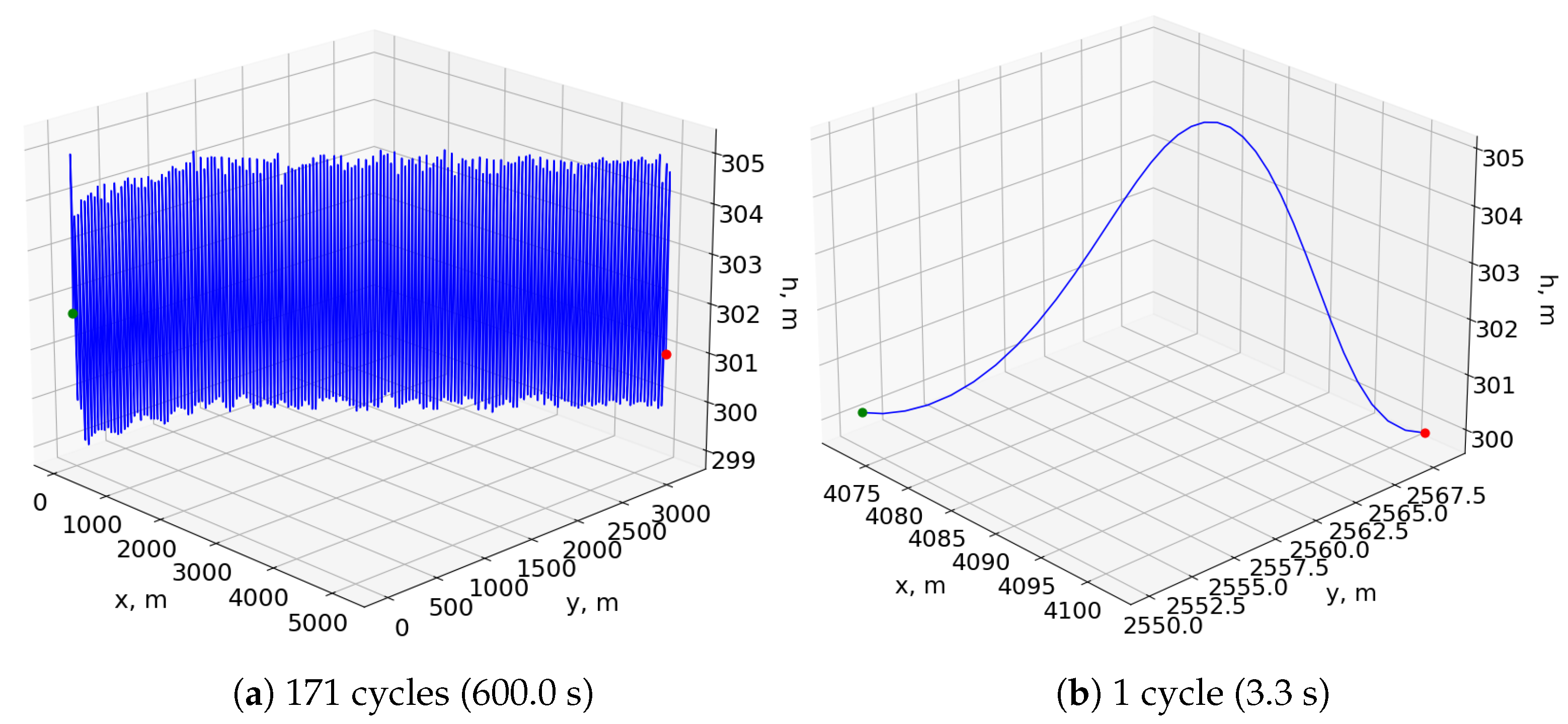
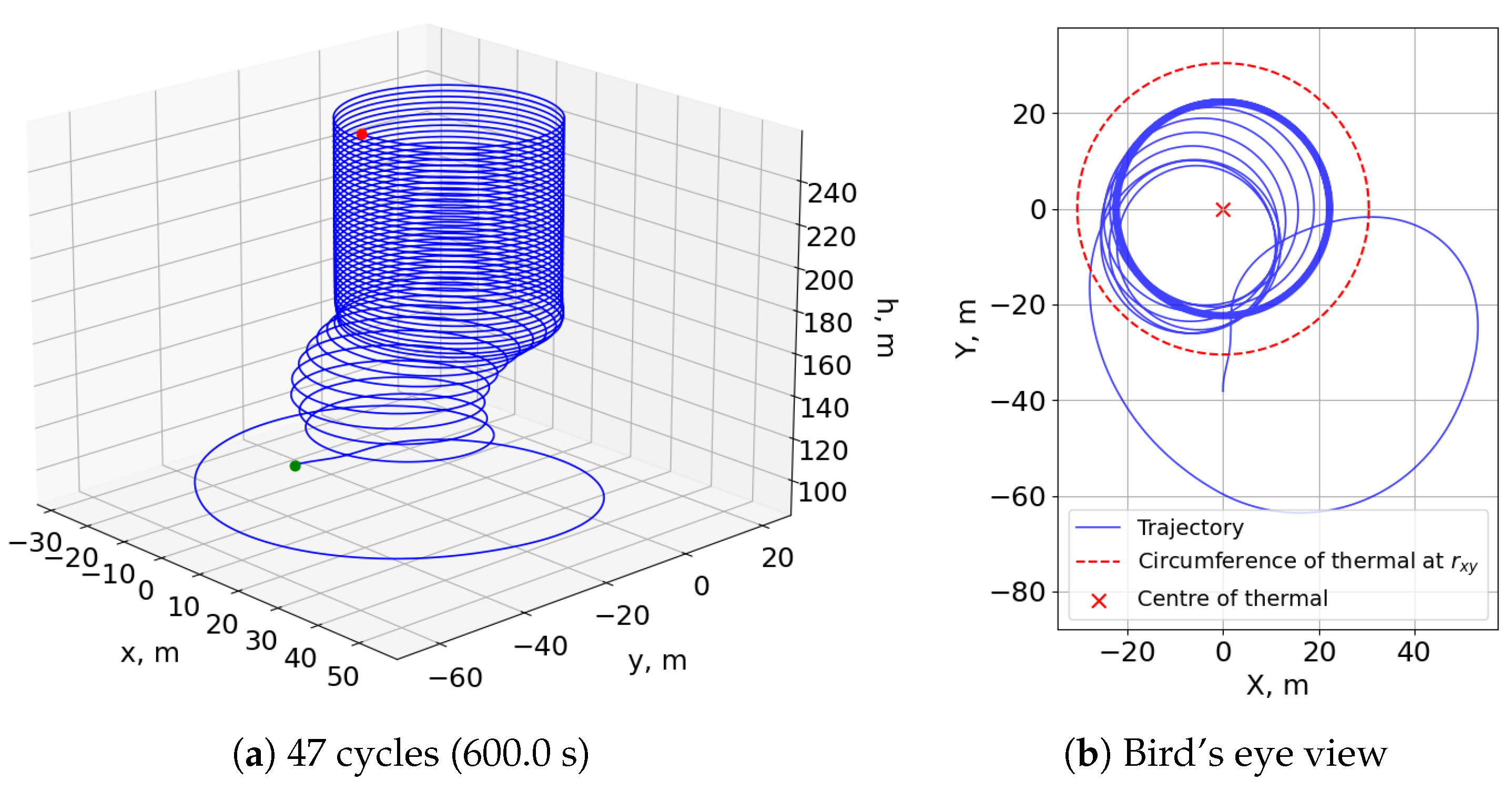
In addition, the fitness function used to generate this neurocontroller only consisted of penalties, unlike the reward-mechanism-containing fitness of the dynamic soaring test cases. The trajectories of Figure 20 demonstrate that an aversion to the extreme penalty of crashing the model was a sufficient motivator for the evolutionary process to develop soaring behavior. The controller initially finds one edge of the thermal bubble before circling around and centering the rising toroid at a radius from the thermal center where the updraft is sufficiently strong for a sustained climb.
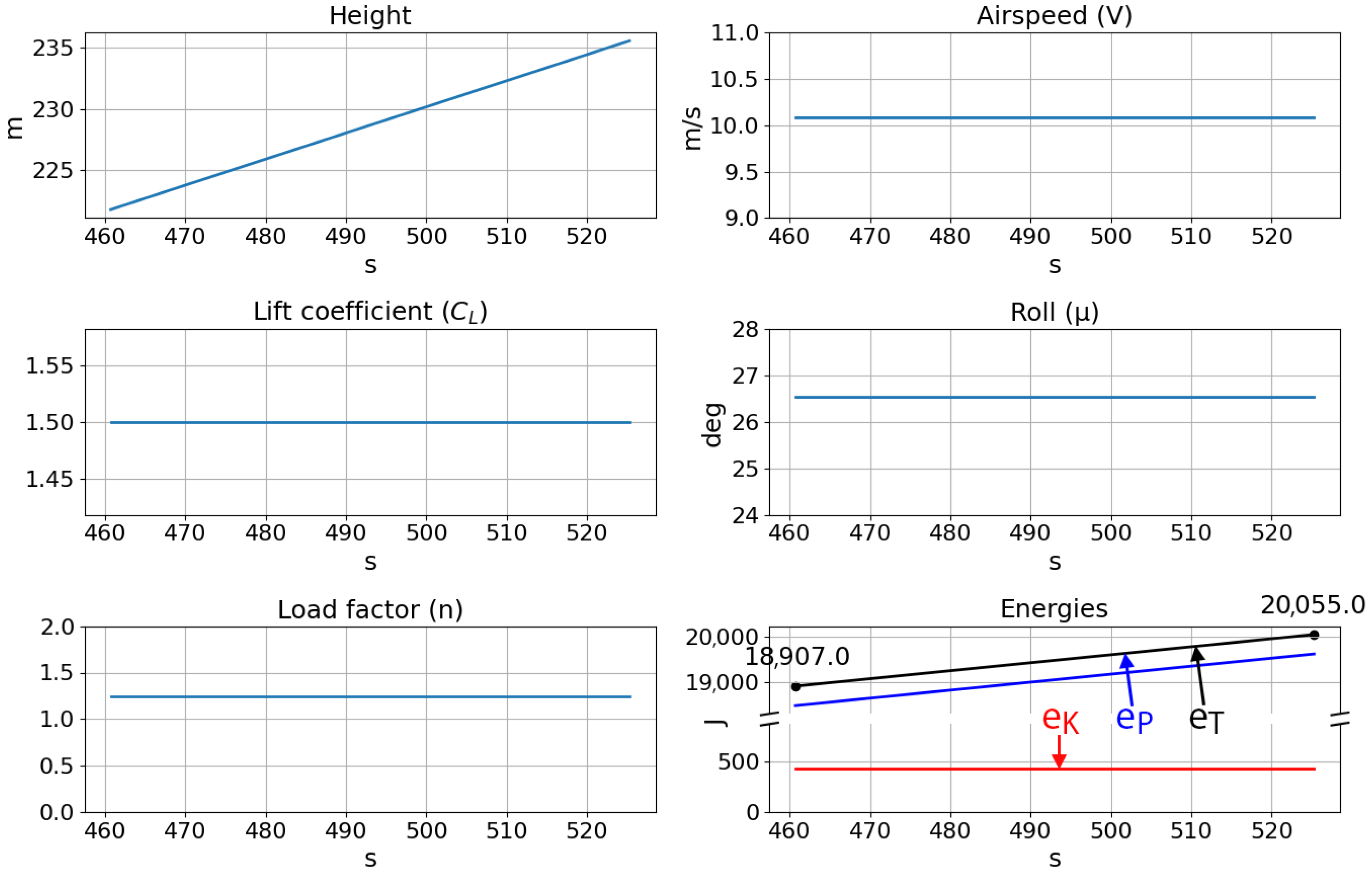
Lastly, the trajectory histories of five soaring loops presented in Figure 21 show the smooth and simple states and controls of the neurocontroller. The roll is maintained at a constant 26.5 degrees, and the lift coefficient also remains at the maximum value so that the SUAV can remain in an optimal soaring region. For instance, at too great a radius from the thermal center, the updraft strength will be insufficient for continued soaring. On the contrary, at too small a radius, the roll angle required to circle the thermal will be greater, resulting in less lift acting on the aircraft, compromising future soaring cycles. Due to these simple controls and the consequent behavior of the flight agent, the SUAV continually gains potential energy while its kinetic energy remains constant. In all, this test case demonstrated the developed neuroevolutionary method’s applicability to other flight maneuvers.
5. Conclusions

This paper presented a method of evolving neurocontrollers for autonomous soaring based on the neuroevolution of augmenting topologies (NEAT) algorithm. The approach was shown to generate simple and efficient neural networks through three distinct test cases. The first used an albatross model to illustrate the similarities between a trained neurocontroller and the flights of biological albatrosses, demonstrating comparable energy extraction maneuvers; the second showed that the proposed approach can be applied to an SUAV model for dynamic soaring at higher altitudes while comparing the resulting trajectories to those of other notable approaches; the third test case presented the method’s applicability to thermal soaring, emphasizing the method’s applicability to other flight techniques. Examining the resulting dynamic soaring trajectories against those of numerical trajectory optimization showed that the neuroevolutionary method generated more practical, cyclic flight paths that were generated in real time without extensive computation. Compared to other neural-network-based learning architectures for trajectory planning and aircraft control, the presented approach only requires a model of the aircraft and wind environment instead of extensive training datasets and yields extremely simple networks exhibiting smooth control signals that are traceable, interpretable, and ultimately implementable. Finally, although this work used deterministic models of the environment, the evolutionary scheme may be adapted for the creation of robust neurocontrollers that can perform soaring in stochastic conditions, moving further towards significantly reducing the energy requirements and flight limits of SUAVs.

Supplementary Materials

Author Contributions

Conceptualization, R.E.P.; funding acquisition, R.E.P.; investigation, E.J.K. and R.E.P.; software, E.J.K.; supervision, R.E.P.; visualization, E.J.K.; writing—original draft, E.J.K.; writing—review and editing, E.J.K. and R.E.P. Both authors have read and agreed to the published version of the manuscript.

Funding

This research is sponsored by a Canadian Defence Academy Research Program Grant, No. 757734, Enhancing UAV Persistent Surveillance through AI-Driven Optimal Atmospheric Energy Extraction. The authors acknowledge as well a scholarship from Defence Research and Development Canada that enabled this research as part of a Master’s program.

Institutional Review Board Statement

Not applicable.

Informed Consent Statement

Not applicable.

Data Availability Statement

Not applicable.

Conflicts of Interest

The authors declare no conflict of interest.

References

  1. Sachs, G. Minimum shear wind strength required for dynamic soaring of albatrosses. Ibis 2005, 147, 1–10. [Google Scholar] [CrossRef]
  2. Pennycuick, C.J. Thermal Soaring Compared in Three Dissimilar Tropical Bird Species, Fregata Magnificens, Pelecanus Occidentals and Coragyps Atratus. J. Exp. Biol. 1983, 102, 307–325. [Google Scholar] [CrossRef]
  3. Sachs, G.; Traugott, J.; Nesterova, A.P.; Dell’Omo, G.; Kümmeth, F.; Heidrich, W.; Vyssotski, A.L.; Bonadonna, F. Flying at No Mechanical Energy Cost: Disclosing the Secret of Wandering Albatrosses. PLoS ONE 2012, 7, e41449. [Google Scholar] [CrossRef] [PubMed]
  4. Allen, M. Autonomous Soaring for Improved Endurance of a Small Uninhabitated Air Vehicle. In Proceedings of the 43rd AIAA Aerospace Sciences Meeting and Exhibit, Reno, NV, USA, 10–13 January 2005; American Institute of Aeronautics and Astronautics: Reno, NV, USA, 2005. [Google Scholar] [CrossRef]
  5. Zhao, Y.J. Optimal patterns of glider dynamic soaring. Optim. Control Appl. Methods 2004, 25, 67–89. [Google Scholar] [CrossRef]
  6. Sachs, G.; Grüter, B. Trajectory Optimization and Analytic Solutions for High-Speed Dynamic Soaring. Aerospace 2020, 7, 47. [Google Scholar] [CrossRef] [Green Version]
  7. Shaw-Cortez, W.E.; Frew, E. Efficient Trajectory Development for Small Unmanned Aircraft Dynamic Soaring Applications. J. Guid. Control Dyn. 2015, 38, 519–523. [Google Scholar] [CrossRef]
  8. Akhtar, N.; Whidborne, J.F.; Cooke, A.K. Real-time optimal techniques for unmanned air vehicles fuel saving. Proc. Inst. Mech. Eng. Part G J. Aerosp. Eng. 2012, 226, 1315–1328. [Google Scholar] [CrossRef]
  9. Gao, C.; Liu, H.H.T. Dubins path-based dynamic soaring trajectory planning and tracking control in a gradient wind field. Optim. Control Appl. Methods 2017, 38, 147–166. [Google Scholar] [CrossRef]
  10. Lawrance, N.R.J.; Sukkarieh, S. A guidance and control strategy for dynamic soaring with a gliding UAV. In Proceedings of the 2009 IEEE International Conference on Robotics and Automation, Kobe, Japan, 12–17 May 2009; pp. 3632–3637. [Google Scholar] [CrossRef]
  11. Pogorzelski, G.; Silvestre, F.J. Autonomous soaring using a simplified MPC approach. Aeronaut. J. 2019, 123, 1666–1700. [Google Scholar] [CrossRef]
  12. Kim, S.h.; Lee, J.; Jung, S.; Lee, H.; Kim, Y. Deep Neural Network-Based Feedback Control for Dynamic Soaring of Unpowered Aircraft. IFAC-PapersOnLine 2019, 52, 117–121. [Google Scholar] [CrossRef]
  13. Montella, C.; Spletzer, J.R. Reinforcement learning for autonomous dynamic soaring in shear winds. In Proceedings of the 2014 IEEE/RSJ International Conference on Intelligent Robots and Systems, Chicago, IL, USA, 14–18 September 2014; pp. 3423–3428. [Google Scholar] [CrossRef]
  14. Woodbury, T.D.; Dunn, C.; Valasek, J. Autonomous Soaring Using Reinforcement Learning for Trajectory Generation. In 52nd Aerospace Sciences Meeting; AIAA SciTech Forum; American Institute of Aeronautics and Astronautics: National Harbor, MD, USA, 2014. [Google Scholar] [CrossRef] [Green Version]
  15. Chung, J.; Lawrance, N.; Sukkarieh, S. Learning to soar: Resource-constrained exploration in reinforcement learning. Int. J. Robot. Res. 2014, 34, 158–172. [Google Scholar] [CrossRef]
  16. Muliadi, J.; Kusumoputro, B. Neural Network Control System of UAV Altitude Dynamics and Its Comparison with the PID Control System. J. Adv. Transp. 2018, 2018, 3823201. [Google Scholar] [CrossRef]
  17. Efe, M.Ö. Neural Network Assisted Computationally Simple PID Control of a Quadrotor UAV. IEEE Trans. Ind. Inform. 2011, 7, 354–361. [Google Scholar] [CrossRef]
  18. Bansal, S.; Akametalu, A.K.; Jiang, F.J.; Laine, F.; Tomlin, C.J. Learning Quadrotor Dynamics Using Neural Network for Flight Control. arXiv 2016, arXiv:1610.05863. [Google Scholar]
  19. Stanley, K.O.; Miikkulainen, R. Evolving Neural Networks through Augmenting Topologies. Evol. Comput. 2002, 10, 99–127. [Google Scholar] [CrossRef] [PubMed]
  20. Perez, R.E.; Arnal, J.; Jansen, P.W. Neuro-Evolutionary Control for Optimal Dynamic Soaring. In Proceedings of the AIAA Scitech 2020 Forum, Orlando, FL, USA, 6–10 January 2020; American Institute of Aeronautics and Astronautics: Orlando, FL, USA, 2020. [Google Scholar] [CrossRef]
  21. Rao, A. A Survey of Numerical Methods for Optimal Control. Adv. Astronaut. Sci. 2010, 135, 497–528. [Google Scholar]
  22. Betts, J.T. Survey of Numerical Methods for Trajectory Optimization. J. Guid. Control Dyn. 1998, 21, 193–207. [Google Scholar] [CrossRef]
  23. Miele, A. Flight Mechanics, Theory of Flight Paths; Addison-Wesley: Reading, MA, USA, 1962; Volume 1. [Google Scholar]
  24. Lawrance, N.; Sukkarieh, S. Wind Energy Based Path Planning for a Small Gliding Unmanned Aerial Vehicle. In Proceedings of the AIAA Guidance, Navigation, and Control Conference, Chicago, IL, USA, 10–13 August 2009; American Institute of Aeronautics and Astronautics: Chicago, IL, USA, 2009. [Google Scholar] [CrossRef]
  25. Perez, R.E.; Jansen, P.W.; Martins, J.R.R.A. pyOpt: A Python-based object-oriented framework for nonlinear constrained optimization. Struct. Multidiscip. Optim. 2012, 45, 101–118. [Google Scholar] [CrossRef]
  26. Li, Z.; Langelaan, J.W. Parameterized Trajectory Planning for Dynamic Soaring. In Proceedings of the AIAA Scitech 2020 Forum, Orlando, FL, USA, 6–10 January 2020; American Institute of Aeronautics and Astronautics: Orlando, FL, USA, 2020. [Google Scholar] [CrossRef]
Figure 1. Free body diagram of the flight agent model.
Aerospace 08 00267 g001
Figure 2. Typical dynamic soaring trajectory with a linear wind gradient (adapted from [5]).
Aerospace 08 00267 g002
Figure 3. Horizontal wind profile shapes, with W m a x x = 10 m / s and h t r x = 30 m .
Aerospace 08 00267 g003
Figure 4. Toroidal thermal bubble model.
Aerospace 08 00267 g004
Figure 5. Comparison of artificial neural network structures.
Aerospace 08 00267 g005
Figure 6. Neurocontroller evolution scheme.
Aerospace 08 00267 g006
Figure 7. Topology of the dynamic soaring albatross neurocontroller.
Aerospace 08 00267 g007
Figure 8. Simulated trajectories of the dynamic soaring albatross neurocontroller, with start marker (green), end marker (red), and path (blue).
Aerospace 08 00267 g008
Figure 9. Trajectory trace of the dynamic soaring albatross neurocontroller.
Aerospace 08 00267 g009
Figure 10. Albatross neurocontroller and biological albatross single-cycle energies.
Aerospace 08 00267 g010
Figure 11. Topology of the dynamic soaring SUAV neurocontroller.
Aerospace 08 00267 g011
Figure 12. Network signal tracing of the dynamic soaring SUAV neurocontroller.
Aerospace 08 00267 g012
Figure 13. Simulated trajectories of the dynamic soaring SUAV neurocontroller.
Aerospace 08 00267 g013
Figure 14. Wind profile for the dynamic soaring SUAV neurocontroller.
Aerospace 08 00267 g014
Figure 15. Trajectory trace of the dynamic soaring SUAV neurocontroller.
Aerospace 08 00267 g015
Figure 16. Aircraft visualization of the dynamic soaring SUAV neurocontroller (Supplementary Materials). The attitude indicator displays the roll angle along its circumference, as well as the pitch angle through the concentric circles within the plot. The shaded red zones represent the roll angle limits. The heading and wind velocities are shown by the blue and green vectors, respectively, where their orientations indicate direction and their lengths indicate the speed.
Aerospace 08 00267 g016
Figure 17. NEAT and TO simulated trajectories of the dynamic soaring SUAV. Neurocontroller in solid, optimized trajectory in dotted.
Aerospace 08 00267 g017
Figure 18. NEAT and TO traces of the dynamic soaring SUAV. The neurocontroller in solid lines; the optimized trajectory in dotted lines.
Aerospace 08 00267 g018
Figure 19. Topology of the thermal soaring SUAV neurocontroller.
Aerospace 08 00267 g019
Figure 20. Simulated trajectories of the thermal soaring SUAV neurocontroller.
Aerospace 08 00267 g020
Figure 21. Trajectory trace of the thermal soaring SUAV neurocontroller.
Aerospace 08 00267 g021
Table 1. Albatross neurocontroller simulation parameters.
Albatross ParametersValueWind ParametersValueTrajectory ParametersValue
g (m/ s 2 )9.8 A x 1.0 V 0 (m/ s 2 )9.1
ρ (kg/ m 3 )1.225 h t r x (m)9.1 ψ 0 (deg)−25
m (kg)8.5 W m a x x (m/ s 2 )10.2 γ 0 (deg)0
S ( m 2 )0.65 h 0 (m)6.1
C D 0 0.033 A y 1.0 x 0 (m)0
E m a x 20.0 h t r y (m)9.1 y 0 (m)0
n m a x 5 W m a x y (m/ s 2 )4.8 h m i n (m)0
C L m a x 1.6 γ ˙ m a x (deg/s)100
C L m i n −0.25 ψ ˙ m a x (deg/s)100
μ m a x (deg)60 C L ˙ m a x 0.25
μ ˙ m a x (deg/s)90
t f (s)600
Table 2. Dynamic soaring SUAV neurocontroller simulation parameters.
SUAV ParametersValueWind ParametersValueTrajectory ParametersValue
g (m/ s 2 )9.8 A x 1.0 V 0 (m/ s 2 )10.7
ρ (kg/ m 3 )1.225 h t r x (m)304.8 ψ 0 (deg)0
m (kg)4.3 W m a x x (m/ s 2 )6.1 γ 0 (deg)0
S ( m 2 )1.0 h 0 (m)301.8
C D 0 0.025 A y N/A x 0 (m)0
E m a x 20.0 h t r y (m)N/A y 0 (m)0
n m a x 15 W m a x x (m/ s 2 )N/A h m i n (m)0
C L m a x 1.5 γ ˙ m a x (deg/s)100
C L m i n −0.2 ψ ˙ m a x (deg/s)100
μ m a x (deg)60 C L ˙ m a x 0.25
μ ˙ m a x (deg/s)90
t f (s)600
Table 3. Dynamic soaring SUAV trajectory optimization constraints.
Boundary t 0 ValueBoundary t f ValuePathMinMax
V 0 (m/s)12.5 V f (m/s)12.5V (m/s)0.01000.0
ψ 0 (deg)60.0 ψ f (deg)60.0 ψ ˙ (deg/s)−100100
γ 0 (deg)0.0 γ f (deg)0.0 γ ˙ (deg/s)−100100
z 0 (m)300.0 z f (m)300.0n0.015.0
x 0 (m)0.0 C L −0.21.5
y 0 (m)0.0
C L 0 1.0 C L f 1.0
μ 0 (deg)−40.0 μ f (deg)−10.0
Table 4. Thermal soaring SUAV neurocontroller simulation parameters.
SUAV ParametersValueWind ParametersValueTrajectory ParametersValue
g (m/ s 2 )9.8 W c o r e (m/s)3.05 V 0 (m/ s 2 )9.1
ρ (kg/ m 3 )1.225 h t 0 (m)91.4 ψ 0 (deg)0
m (kg)4.3 r x y (m)30.5 γ 0 (deg)0
S ( m 2 )1.0 r z (m)61.0 h 0 (m)106.7
C D 0 0.025 h t ˙ (m/s)0.213 x 0 (m)0
E m a x 20.0 y 0 (m)−38.1
n m a x 15 W m a x x (m/ s 2 )N/A h m i n (m)0
C L m a x 1.5 W m a x x (m/ s 2 )N/A γ ˙ m a x (deg/s)100
C L m i n −0.2 ψ ˙ m a x (deg/s)10
μ m a x (deg)60 C L ˙ m a x 0.25
μ ˙ m a x (deg/s)90
t f (s)600
Publisher’s Note: MDPI stays neutral with regard to jurisdictional claims in published maps and institutional affiliations.