
Modeling and Simulation of Heavy-Lift Tethered Multicopter Considering Mechanical Properties of Electric Power Cable


Abstract
:1. Introduction
2. Design of Heavy-Lift Tethered Multicopter
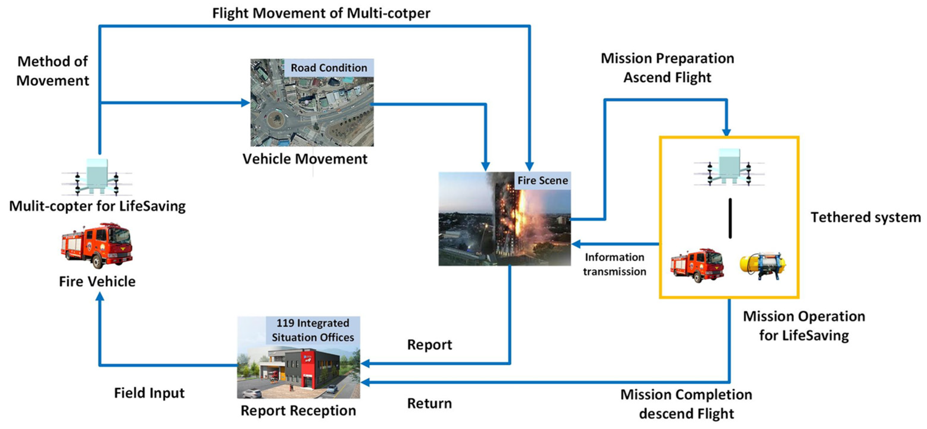
2.1. Mission Profile
2.2. Analysis on Design Constraints
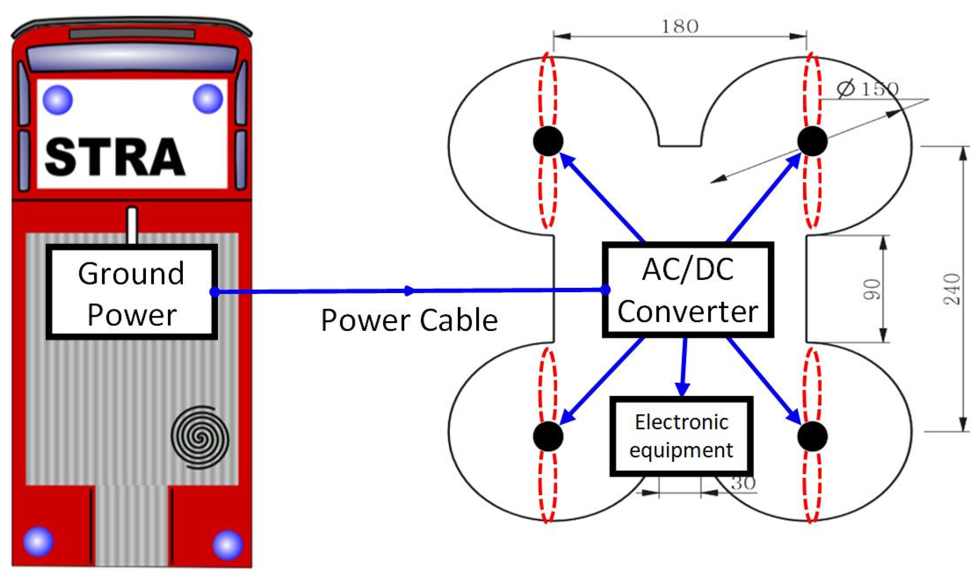
2.2.1. Size Constraints
2.2.2. Weight Constraints
2.2.3. Initial Design of Tethered Flight System
3. Flexible Multi-Body Dynamics Simulation of Heavy-Lift Tethered Multicopter
3.1. Mechanical Properties of Power Cable
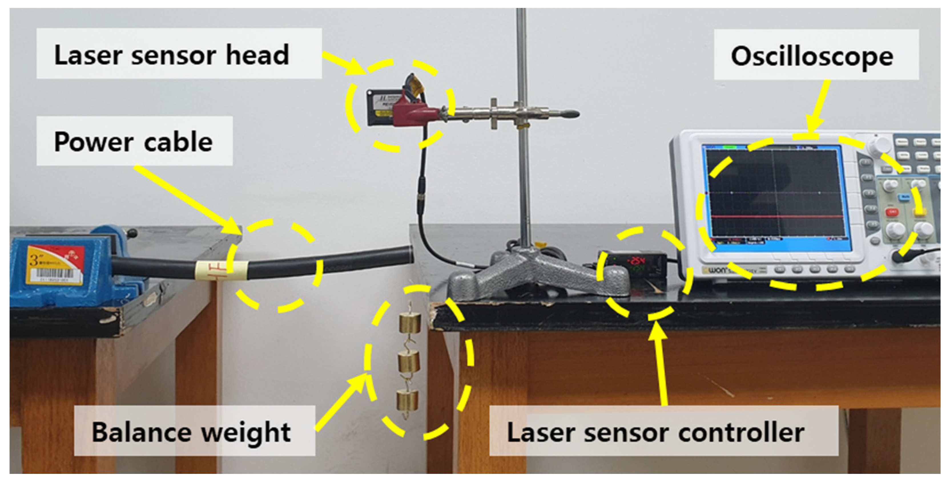
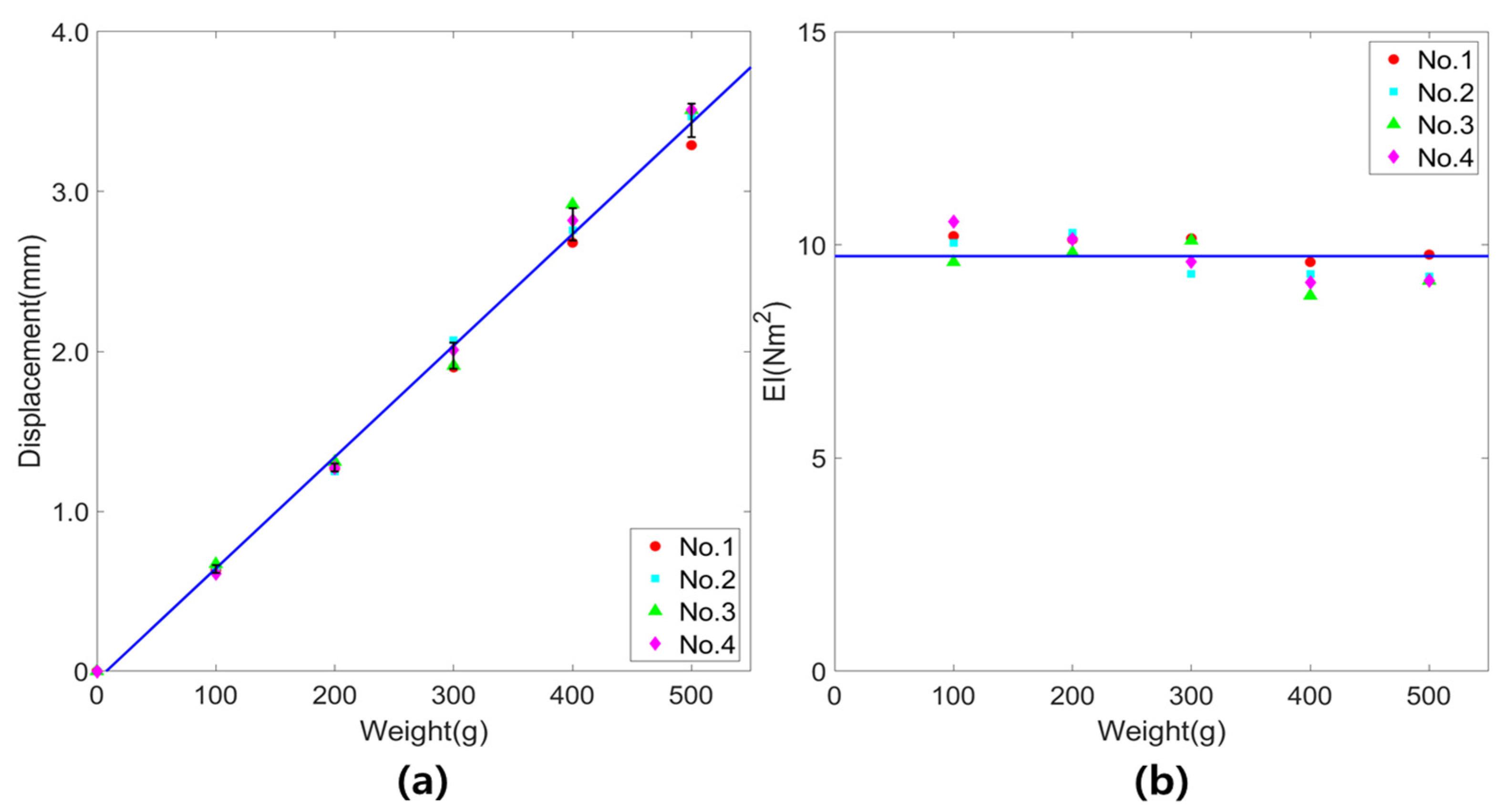
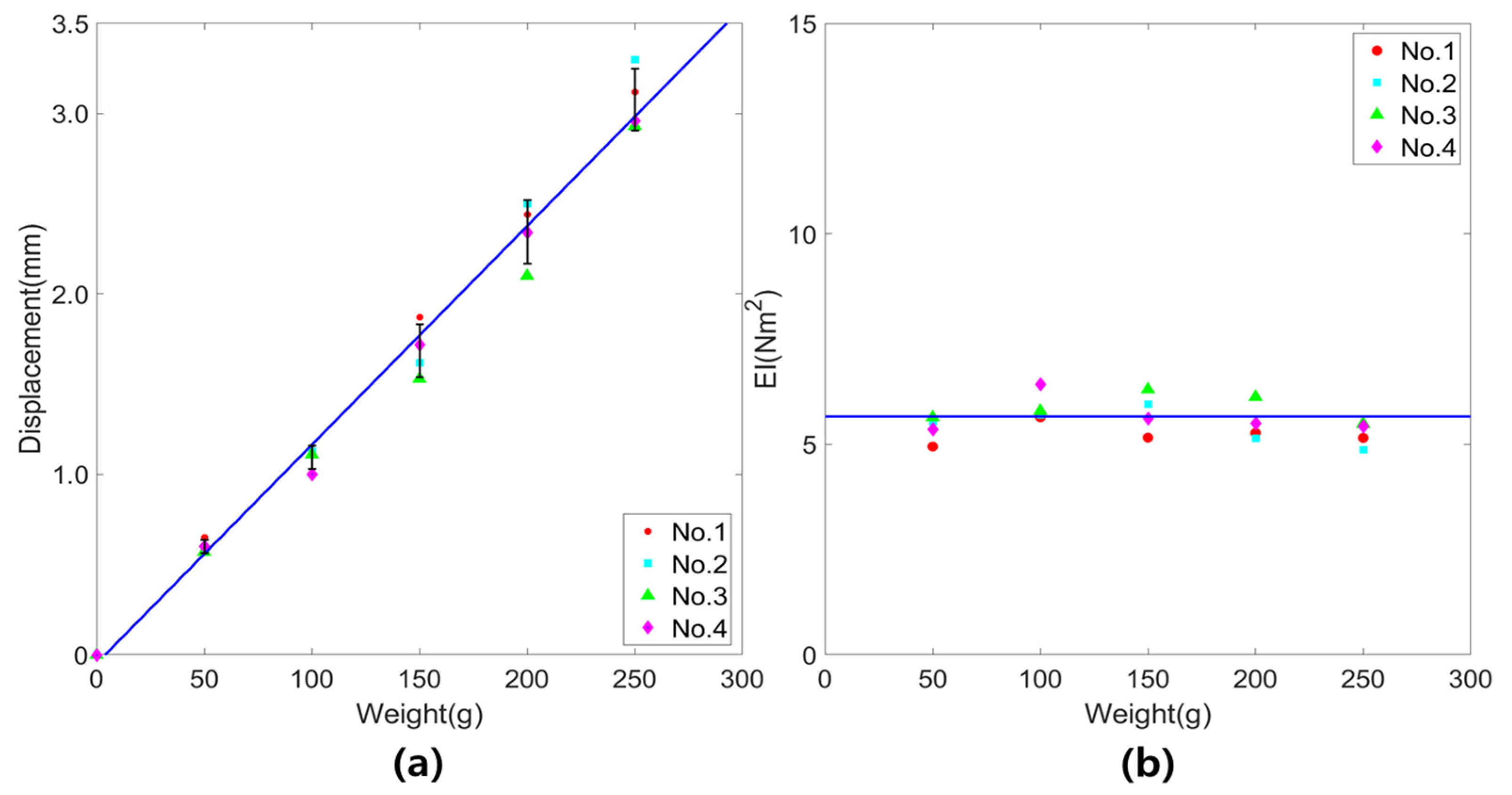
3.1.1. Static Bending Test
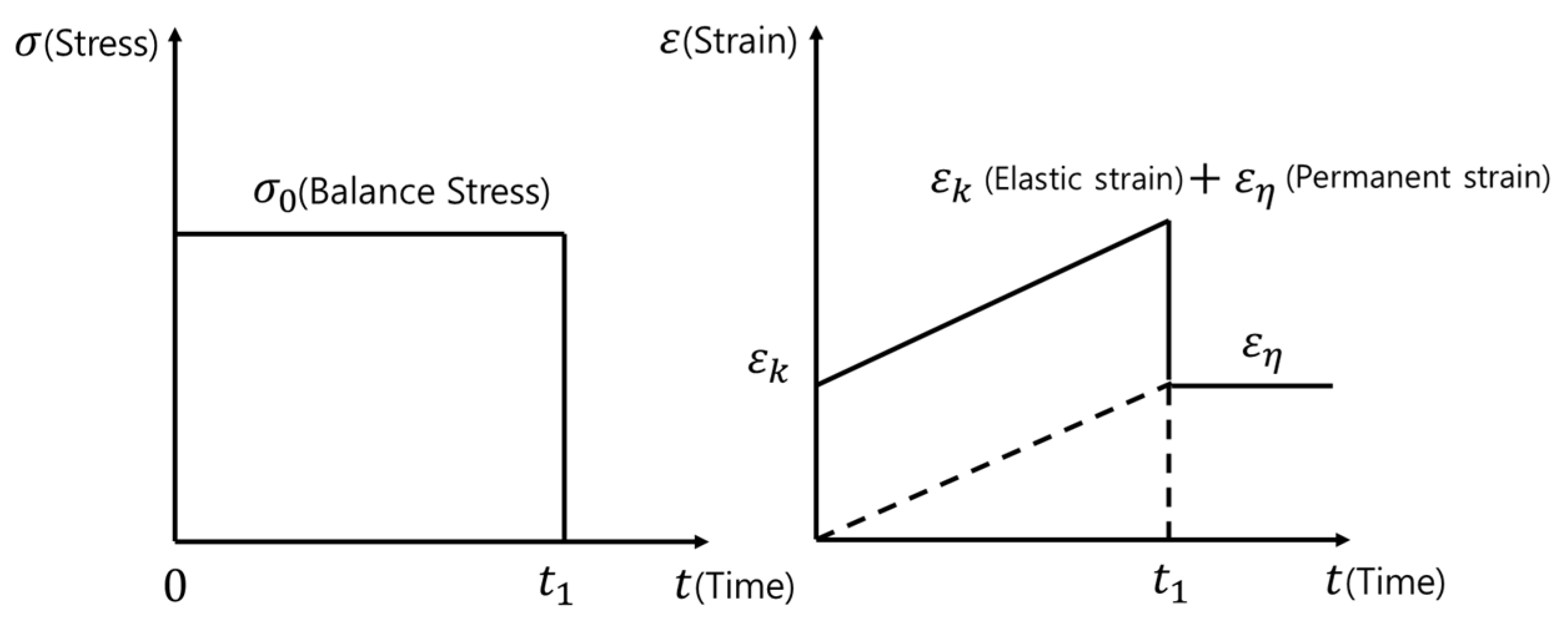
3.1.2. Consideration of Viscoelasticity
3.2. Position and Attitude Control Simulation of Tethered Multicopter
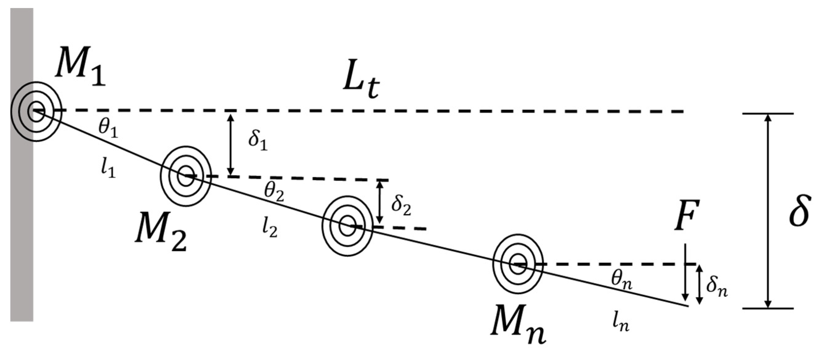
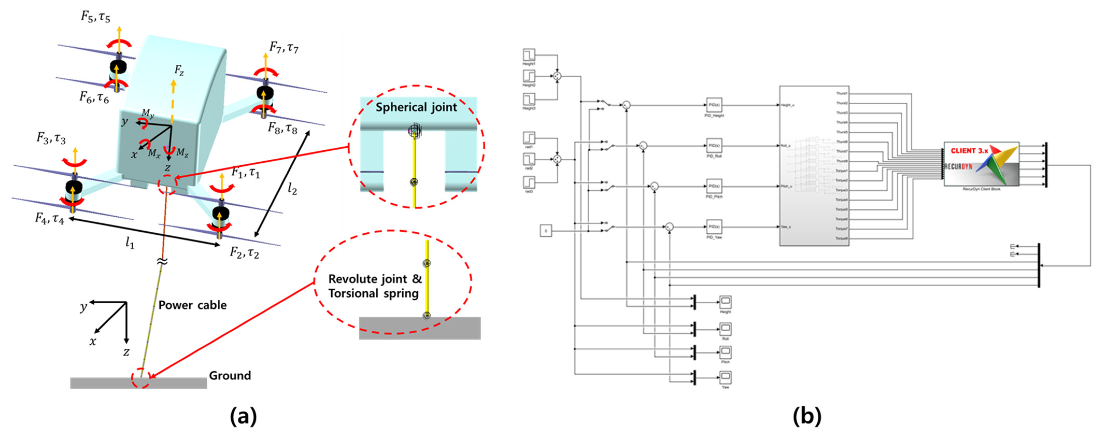
3.2.1. Flexible Multi-Body Dynamics Modeling
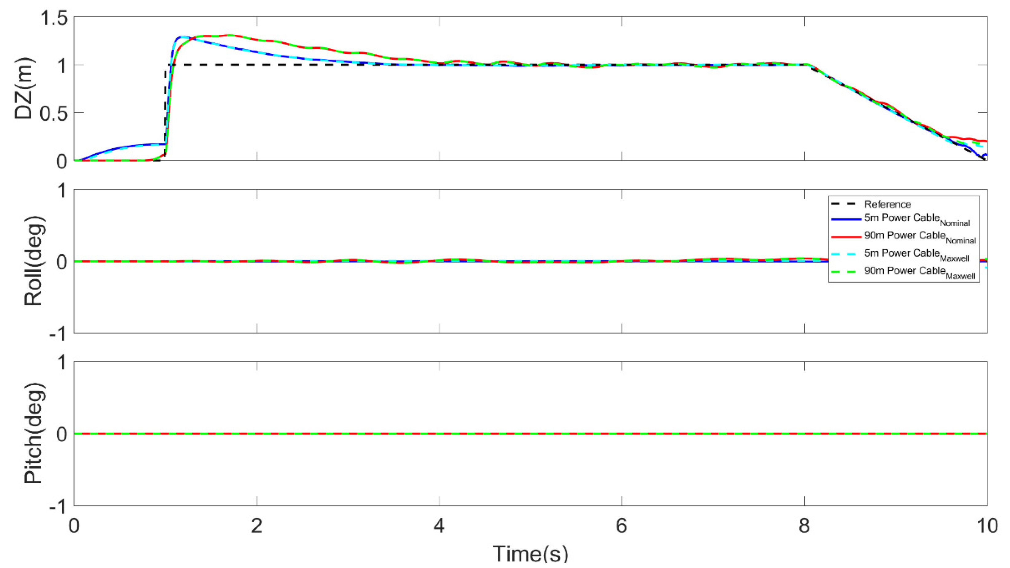
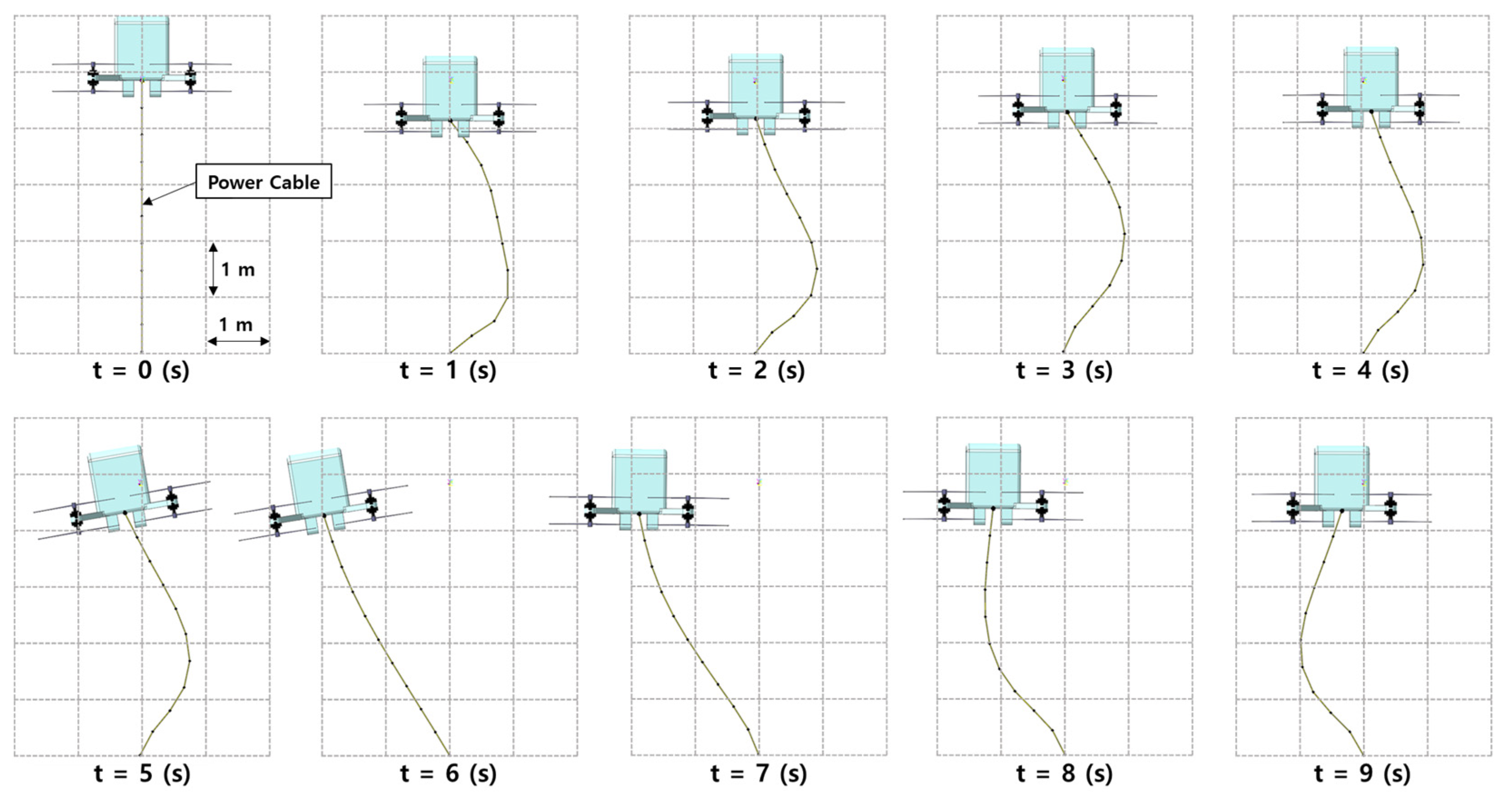
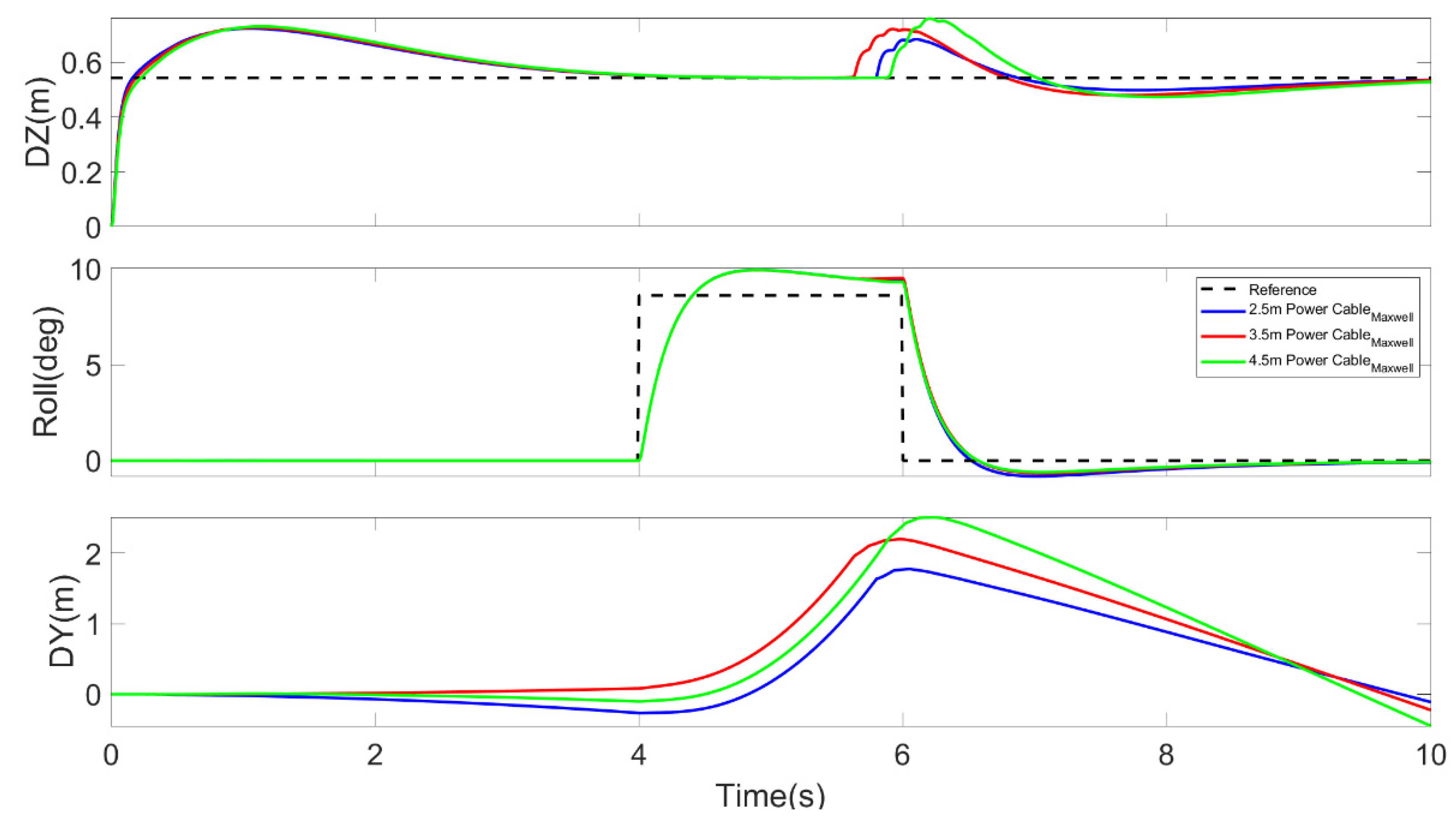
3.2.2. Position and Attitude Control Simulation
4. Conclusions
Author Contributions
Funding
Institutional Review Board Statement
Informed Consent Statement
Data Availability Statement
Acknowledgments
Conflicts of Interest
References
- Alieksieiev, V.; Markovych, B. Implementation of UAV for environment monitoring of a Smart City with an airspace regulation by AIXM-format data streaming. Industry 4.0 2020, 5, 90–93. [Google Scholar]
- Ramesh, P.S.; Jeyan, J.M.L. Comparative analysis of the impact of operating parameters on military and civil applications of mini unmanned aerial vehicle (UAV). Proc. AIP Conf. 2020, 2311, 030034. [Google Scholar]
- Woźniak, W.; Jessa, M. Selection of Solar Powered Unmanned Aerial Vehicles for a Long Range Data Acquisition Chain. Sensors 2021, 21, 2772. [Google Scholar] [CrossRef] [PubMed]
- Bogue, R. Fruit picking robots: Has their time come? Ind. Rob. 2020, 47, 141–145. [Google Scholar] [CrossRef]
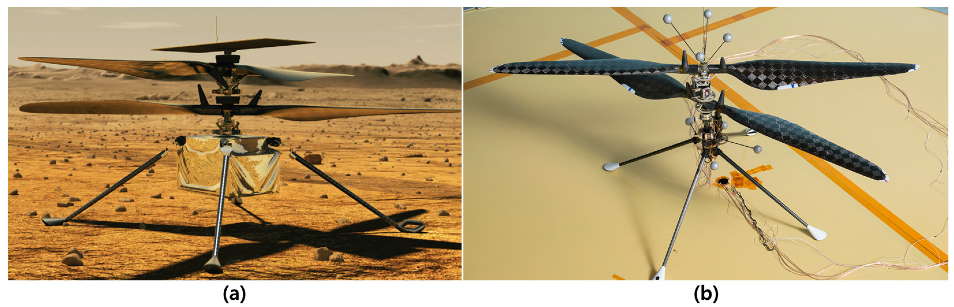
- Koning, W.J.; Johnson, W.; Grip, H.F. Improved Mars helicopter aerodynamic rotor model for comprehensive analyses. AIAA J. 2019, 57, 3969–3979. [Google Scholar] [CrossRef] [Green Version]
- Illustration of Mars Helicopter. Available online: https://www.nasa.gov/aeroresearch/nasa-aeronautics-experts-help-prepare-ingenuity-to-fly-on-mars (accessed on 24 June 2021).
- Grip, H.F.; Johnson, W.; Malpica, C.; Scharf, D.P.; Mandić, M.; Young, L.; Allan, B.; Mettler, B.; Martin, M.S.; Lam, J. Modeling and Identification of Hover Flight Dynamics for NASA’s Mars Helicopter. J. Guid. Control Dyn. 2020, 43, 179–194. [Google Scholar] [CrossRef]
- Mars Helicopter Prototype. Available online: https://mars.nasa.gov/resources/22372/mars-helicopter-prototype/ (accessed on 24 June 2021).
- Hascaryo, R.W.; Merret, J.M. Configuration-Independent Initial Sizing Method for UAM/eVTOL Vehicles. In Proceedings of the AIAA AVIATION Forum 2020, Dalas, TX, USA, 17–19 June 2020; p. 2630. [Google Scholar]
- Bacchini, A.; Cestino, E. Electric VTOL configurations comparison. Aerospace 2019, 6, 26. [Google Scholar] [CrossRef] [Green Version]
- Busan, R.C.; Murphy, P.C.; Hatke, D.B.; Simmons, B.M. Wind Tunnel Testing Techniques for a Tandem Tilt-Wing, Distributed Electric Propulsion VTOL Aircraft. In Proceedings of the AIAA SciTech 2021 Forum, Nashville, TN, USA, 11–15 January 2021; p. 1189. [Google Scholar]
- Beak, S.C. A Study of Fire-truck Design for the Possible Suppression and Respond of Initial Fire. Master’s Thesis, Hongik University, Seoul, Korea, 2018. [Google Scholar]
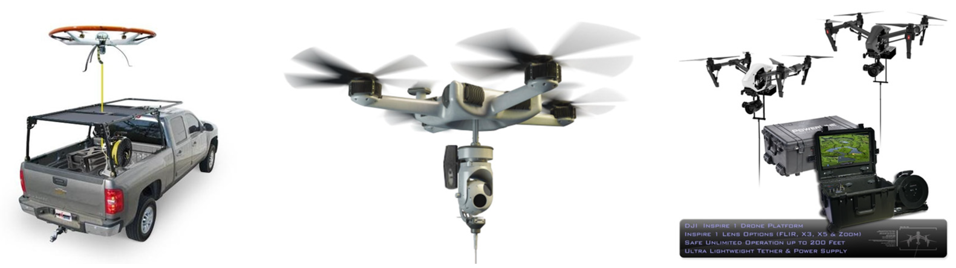
- UCON System. Available online: http://www.uconsystem.com/eng/products/military/trotor.asp (accessed on 15 June 2021).
- Skysapience. Available online: https://skysapience.com/drone/hovermast-150-c/ (accessed on 24 June 2021).
- Powerline. Available online: https://www.ntpdrone.com/product/ (accessed on 15 June 2021).
- Giernacki, W.; Gośliński, J.; Goślińska, J.; Espinoza-Fraire, T.; Rao, J. Mathematical Modeling of the Coaxial Quadrotor Dynamics for Its Attitude and Altitude Control. Energies 2021, 14, 1232. [Google Scholar] [CrossRef]
- Ivler, C.; Niemiec, R.; Gandhi, F.; Sanders, F.C. Multirotor Electric Aerial Vehicle Model Validation with Flight Data: Physics-Based and System Identification Models. In Proceedings of the VFS 75th Annual Forum, Fairfax, VA, USA, 13–16 May 2019; pp. 1–26. [Google Scholar]
- Aslanov, V.S.; Ledkov, A.S. Dynamics of Tethered Satellite Systems; Woodhead Publishing Ltd.: Cambridge, UK, 2012. [Google Scholar]
- Misra, A.K.; Xu, D.M.; Modi, V.J. On vibrations of orbiting tethers. Acta Astronaut. 1986, 13, 587–597. [Google Scholar] [CrossRef]
- Lorenzini, E.C.; Cosmo, M.; Vetrella, S.; Moccia, A. Dynamics and control of the tether elevator/crawler system. J. Guid. Control Dyn. 1989, 12, 404–411. [Google Scholar] [CrossRef]
- Williams, P.; Blanksby, C.; Yeo, S. Heating and modeling effects in tethered aerocapture missions. J. Guid. Control Dyn. 2003, 26, 643–654. [Google Scholar] [CrossRef]
- Buler, W.; Sibilski, K.; Winczura, Z.; Zyluk, A. Nonlinear dynamics of helicopter with slung load analysis by continuation methods. In Proceedings of the 39th Aerospace Sciences Meeting and Exhibit, Reno, NV, USA, 8–11 January 2001; p. 110. [Google Scholar]
- Notter, S.; Heckmann, A.; Mcfadyen, A.; Gonzalez, F. Modelling, simulation and flight test of a model predictive controlled multirotor with heavy slung load. IFAC PapersOnLine 2016, 49, 182–187. [Google Scholar] [CrossRef] [Green Version]
- De Angelis, E.L. Swing angle estimation for multicopter slung load applications. Aerosp. Sci. Technol. 2019, 89, 264–274. [Google Scholar] [CrossRef]
- Youn, G.H. Sersive Design for using the Drones in the Early Stages fires of Dense Residential Area. J. Korean Contents Soc. 2019, 19, 111–121. [Google Scholar]
- Kim, K.T.; Park, M.S.; Park, S.W.; Park, S.H. The Concept of Operations of the Multicopter UAVs for Disater and Public Safety-Based on Mission Scenarios. Curr. Ind. Technol. Trends Aerosp. 2017, 15, 84–96. [Google Scholar]
- Khofiyah, N.A.; Sutopo, W.; Nugroho, B.D.A. Technical Feasibility Battery Lithium to Support Unmanned Aerial Vehicle (UAV). In Proceedings of the International Conference on Industrial Engineering and Operations Management, Bangkok, Thailand, 5–7 March 2019; pp. 3591–3601. [Google Scholar]
- Ogumi, Z.; Sutopo, W.; Nugroho, B.D.A. Lithium Secondary Batteries; A-JIN Publishing Co., Ltd.: Seoul, Korea, 2019. [Google Scholar]
- Critique of Battery Powered Flying Car. Available online: https://moller.com/brochures/Critique-of-Battery-Powered-Flying-Cars.pdf (accessed on 24 June 2021).
- Brombach, J.; Schröter, T.; Luecken, A.; Schulz, D. Optimizing the weight of an aircraft power supply system through a +/−270 VDC main voltage. Gen 2012, 360, 800. [Google Scholar]
- Guedes, R.M. Creep and Fatigue in Polymer Matrix Composites, 2nd ed.; Woodhead Publishing Co., Ltd.: Duford, UK, 2019. [Google Scholar]
- Bunge, C.A.; Gries, T.; Beckers, M. Polymer Optical Fibers; Woodhead Publishing Co., Ltd.: Duford, UK, 2017. [Google Scholar]
- Tang, H.; Zhang, D.; Guo, S.; Qu, H. A Novel Model to Simulate Flexural Complements in Comliants Sensor Systems. Sensors 2018, 18, 1029. [Google Scholar] [CrossRef] [PubMed] [Green Version]
- Lo, Y.; Chen, T.C.; Ho, T.L. Design in triangle-profiles and T-profiles of a wirebond using a linkage-spring model. IEEE Trans. Compon. Packaging Manuf. Technol. 2001, 24, 457–467. [Google Scholar]


| Components | Operational Constraints |
|---|---|
| Loading vehicle | Road slope < 5° Ground rigidity should be ensured |
| Outrigger | Maximum allowable load: 80 T Deployment radius: 5.2 m Deployment angle: −7°~70° |
| Lift | Working speed: 1 m/s Ladder deployment angle: 30°~−70° Ladder deployment length: 23~53.2 m |
| Type | Length (mm) | Width (mm) | Height (mm) |
|---|---|---|---|
| Large | 8500 | 2500 | 3400 |
| Medium | 8000 | 2500 | 3200 |
| Small | 6800 | 1900 | 2800 |
| Light | 5200 | 1200 | 2800 |
| Manufacturer | Ehang | Airbus | Volocopter |
|---|---|---|---|
| Model | Ehang 184 | City Airbus | 2X |
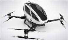 |  | 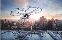 | |
| Size (m) | 4 × 3.9 × 1.4 | 8 × 8 | 3.2 × 9.15 × 2.15 |
| MTOW (kgf) | 360 | 2200 | 450 |
| Payload (kgf) | 100 | 250 | 150 |
| Cable Type | Length (mm) | Diameter (mm) | Weight Per Unit Length (kgf/m) |
|---|---|---|---|
| HF-CO | 400 | 17 | 0.78 |
| TFR-CV | 400 | 17 | 0.79 |
| TFR-8 | 400 | 20 | 0.83 |
| Cable Type | Equivalent Flexural Rigidity (Nm2) | Standard Deviation (Nm2) |
|---|---|---|
| HF-CO | 9.74 | 0.48 |
| TFR-CV | 5.66 | 0.42 |
| TFR-8 | 2.53 | 0.13 |
| Measured Displacements | No. 1 | No. 2 | No. 3 | No. 4 |
|---|---|---|---|---|
| Maximum displacement () [mm] | 2.53 | 2.67 | 2.72 | 2.51 |
| Permanent displacement () [mm] | 1.57 | 1.88 | 1.77 | 1.62 |
| Mass (kg) | Moment of Inertia (kg mm2) | |
|---|---|---|
| m = 137 | Ixx = 3.30 × 10⁹ | Ixy = 7.39 × 10³ |
| Iyy = 4.88 × 10⁹ | Iyz = −6.65 × 10² | |
| Izz = 4.39 × 10⁹ | Izx = −5.86 × 10² | |
Publisher’s Note: MDPI stays neutral with regard to jurisdictional claims in published maps and institutional affiliations. |
© 2021 by the authors. Licensee MDPI, Basel, Switzerland. This article is an open access article distributed under the terms and conditions of the Creative Commons Attribution (CC BY) license (https://creativecommons.org/licenses/by/4.0/).
Share and Cite
Kwon, H.-M.; Lee, D.-K. Modeling and Simulation of Heavy-Lift Tethered Multicopter Considering Mechanical Properties of Electric Power Cable. Aerospace 2021, 8, 208. https://doi.org/10.3390/aerospace8080208
Kwon H-M, Lee D-K. Modeling and Simulation of Heavy-Lift Tethered Multicopter Considering Mechanical Properties of Electric Power Cable. Aerospace. 2021; 8(8):208. https://doi.org/10.3390/aerospace8080208
Chicago/Turabian StyleKwon, Hyeok-Min, and Dong-Kyu Lee. 2021. "Modeling and Simulation of Heavy-Lift Tethered Multicopter Considering Mechanical Properties of Electric Power Cable" Aerospace 8, no. 8: 208. https://doi.org/10.3390/aerospace8080208
APA StyleKwon, H.-M., & Lee, D.-K. (2021). Modeling and Simulation of Heavy-Lift Tethered Multicopter Considering Mechanical Properties of Electric Power Cable. Aerospace, 8(8), 208. https://doi.org/10.3390/aerospace8080208