1. Introduction
The growing interest in space exploration has already led to, and in the near future will only increase, the need to solve the problem associated with a large number of spent space technology objects and their fragments in near-earth orbit, known as the “space debris” (SD) problem [
1,
2]. One of its possible solutions is seen in the use of special service spacecraft to remove SD [
3]. Currently, research to develop the contact-free SD removal method using a wedge-shaped ion beam is conducted at the Research Institute of Applied Mechanics and Electrodynamics of the Moscow Aviation Institute. The essence of such a method of removal is to change the trajectory of a SD object by transferring the momentum of the accelerated ion beam to its surface. One of the problems of this approach is the ion beam divergence, which leads to the fact that in order to ensure efficient removal, the service spacecraft must be located as close to the removable object as possible. However, too close an approach will lead to severe contamination of the spacecraft surfaces with the sprayed SD material. Therefore, it is advisable to locate the service spacecraft as far as possible from the object to be removed. This, in turn, raises the ion beam divergence requirements imposed to the ion injector used for this purpose.
The radio-frequency (RF) ion injector laboratory model, which provides narrow angles of the ion beam divergence (a half-angle of less than 4°), was manufactured and tested to study the possibility of implementing this idea [
4,
5]. When compared to the traditional schemes (based on a volumetric DC discharge), the choice of an electrodeless RF discharge as an ion source allows to increase the lifetime and reduce the weight of both the injector itself and of its power supply system, which is important for space technology. This is due to the fact that RF discharges require fewer units in the power supply system in order to maintain the discharge in the discharge chamber, and there is no need for a massive magnetic system required to hold the electrons in the discharge. At the same time, one of the important factors that must be taken into account when developing an ion injector for its use on board a spacecraft is an increased requirement for the efficiency of its operation, associated with restrictions imposed by the available on-board power. In addition, high power consumption for the ionization of the propellant atoms is one of the main disadvantages of RF plasma [
6].
Since the design and operation principle of the ion injector are identical to those of a radio-frequency ion thruster (RIT), the same methods of increasing its operation efficiency are applicable to it. Various researchers have carried out extensive works on optimizing the size of the discharge chamber [
7] and its shape [
8,
9], selecting the optimal antenna configuration [
7,
10,
11], as well as optimizing the geometric parameters of the ion-extraction system [
12]. Those studies have made it possible to significantly improve the power performance of RIT, modern models of which, in some cases (mainly within the thruster family with a power consumption of up to 1 kW), are close in efficiency to the thrusters based on the DC discharge [
13,
14]. However, the search for new methods to further improve the performance of RF discharge devices is an integral part of space technology development, including in the field of solving the SD removal problem.
As has been shown for the operation of RF technological models [
15], it is possible to increase the power efficiency additionally by placing a dielectrically coated antenna inside the injector discharge chamber. In this case, due to the absence of RF power dissipation outside the discharge volume, it will be used for heating the electrons in plasma to a greater extent, and this will ultimately make it possible to increase the injector operation efficiency. At the same time, it is necessary to take into account that there will be an increase in the surface area (the surface of the antenna turns), on which the charged particle recombination will occur, which is one of the main processes governing the energy loss in the RF plasma. Therefore, it was necessary to carry out a theoretical study to assess possible increases in injector characteristics due to placing an antenna inside the DC.
Four internal antenna configurations and two configurations with a traditional external antenna, located on the DC side surface (side antenna) and on its end surface (flat antenna), were considered using the simplified mathematical model proposed in [
16]. The model used in the calculation was developed to assess the RIT integral characteristics and the distribution of local plasma parameters in its discharge chamber. It was built taking into account plasma parameters that are characteristic for such devices: a plasma density of 10
16–10
17 1/m
3, a density of neutral particles of approximately 10
19 1/m
3 and an electron temperature of approximately 3–5 eV. Schematics of all considered ion injector configurations are shown in
Figure 1.
2. Simulation Setup
The calculation was carried out in the COMSOL Multiphysics software package [
17] in an axisymmetric problem statement. When simulating the plasma, we considered the stationary steady state of the RF discharge, without taking into account the process of its initiation. The simulation was carried out for an ion injector with a cylindrical DC with a height of 50 mm and a diameter of 104 mm. The calculation domain is shown in
Figure 2 for the case of the side antenna.
In the calculations, the propellant (xenon) was assumed to be fed through the gas distributor side surface, and the alternating current amplitude value was set through the antenna turn cross-section variation. The ion-extraction system is set in the form of a single boundary, which, through the transparency of the extraction and accelerating grids, defines the number of ions and atoms of the propellant escaping from the injector. The ion beam focusing and acceleration are not considered in this case.
When calculating the ion injector configurations with an internal antenna, it was necessary to take into account the fact that a part of the charged particle flow reaching the antenna turns will be reflected from them without making a contribution to the energy losses associated with their recombination on the surface. In addition, it is worth noting that a strong electromagnetic field on the surface of the antenna turns can also affect the process of charged particles recombination. Therefore, an accommodation coefficient was introduced to the model, which defines the share of reflected particles. The value of this coefficient depends on a large number of different factors: the propellant atom mass and energy, the temperature and the material of the surface onto which the particles fall. In our conditions, some of these factors will depend on the ion injector operating mode (propellant flow rate and the antenna RF power). Therefore, the accommodation coefficient real value will also be different for each considered case. For simplicity, the accommodation coefficient in the model was assumed to be constant: a = 0.45. This value was obtained in [
18] by the calculation for xenon, which is supposed to be used as a propellant for the considered injector. Taking this coefficient into account, an additional boundary condition, which describes the neutral particle backflow from the internal antenna surface, was introduced into the simplified mathematical model [
16]:
where
is the charged particle density for ions and electrons, respectively;
is the Boltzmann constant;
is the electron temperature;
is the ion mass. It should be noted that a change in the coefficient a, by ±0.05, for example, affects both the calculated value of the extracted ion beam current in the range of ±1.5% and the value of the RF power input into the plasma within ±2%.
In the internal antenna presence, the equation for the preliminary estimation of atom density [
16], which in the first approximation is assumed to be uniform over the entire DC volume, will take the following form:
where
is the DC internal surface area;
is the internal inductor surface area;
is the DC internal volume;
is the propellant ionization coefficient. Taking into account the internal antenna presence, the balance between the energy input to the plasma and the losses will be determined by the following expression:
Here,
is the frequency of elastic collisions of electrons with propellant atoms;
is the frequency of electron–ion interactions, which is defined through the Coulomb logarithm (
);
is the electron mass;
is the amplitude electron velocity;
is the Bohm ion velocity;
is the elementary charge;
is the effective energy of xenon atom ionization [
19];
is the effective electron temperature, which includes thermal and kinetic energy;
is the plasma potential drop in the near-wall sheath;
is the temperature of the DC wall and antenna surface.
To describe the two-dimensional distribution of the propellant atom density in the model, we used the following analytical expression obtained by considering a one-dimensional problem of gas flow in a pipe:
where
is the thermal velocity of atoms and
is the characteristic size of the plasma formation (in the model it is equal to the DC radius).
The distribution of charged particles density over the DC volume was defined by the following expression:
The amplitude of electron velocity
, which it acquires in the vortex electric field, was defined through the value of vector magnetic potential
:
where
is the circular frequency of the RF field.
The following expression was used to define the extracted ion current:
where
is the emission grid transparency and
is the Bohm ion velocity.
In addition to (1), the following boundary conditions were used in the model:
—at the boundary of calculation area, the condition for the magnetic field absence was set:
where
is the normal to the calculation area boundary;
—on the DC walls, the condition of no flow of propellant atoms and ions through the walls was set:
where
and
are the perpendicular components of the velocity of propellant atoms and ions onto the DC wall; and the reverse neutral particle flow, which was determined by ions falling onto the walls with the Bohm velocity, was set:
—on the ion-extraction system boundary, the condition defining the number of atoms es-caping through it was set:
where
is the density of atoms moving in the direction of the ion-extraction system, and
is the accelerating grid transparency;
—and the common condition for the DC walls, ion-extraction system boundary and antenna turns (for inner antenna configurations), which takes into account the charged particles flow, was set also:
where
is the normal to the DC walls, surface of the inner antenna turns and the ion-extraction system boundary.
The finite element meshing in the model was carried out with the maximum element size of 0.01 m and the minimum size of 1.5·10
−3 m. A reduction of the elements density by more than 30% led to the solution nonconvergence. With a 30% reduction in the mesh density, the values of the integral characteristics (extracted ion current and RF power input to the plasma) decreased by approximately 0.5%. An increase in the mesh density had practically no effect on the calculation results. An increase by a factor of 2 led to a change in the values of the integral characteristics by slightly more than 0.04%. A more detailed description of the model is presented in [
16].
3. Calculation Results
Characteristics at different antenna configurations were compared using the dependences of the ion beam current extracted from the injector on the input RF power, which were calculated at the xenon flow rates of 0.5 and 1 mg/s and are shown in
Figure 3 and
Figure 4. The antenna current frequency in the calculation was 2 MHz. Such a frequency of the antenna current corresponds to the frequency at which the ion injector with a weakly diverging ion beam was studied experimentally at MAI [
4].
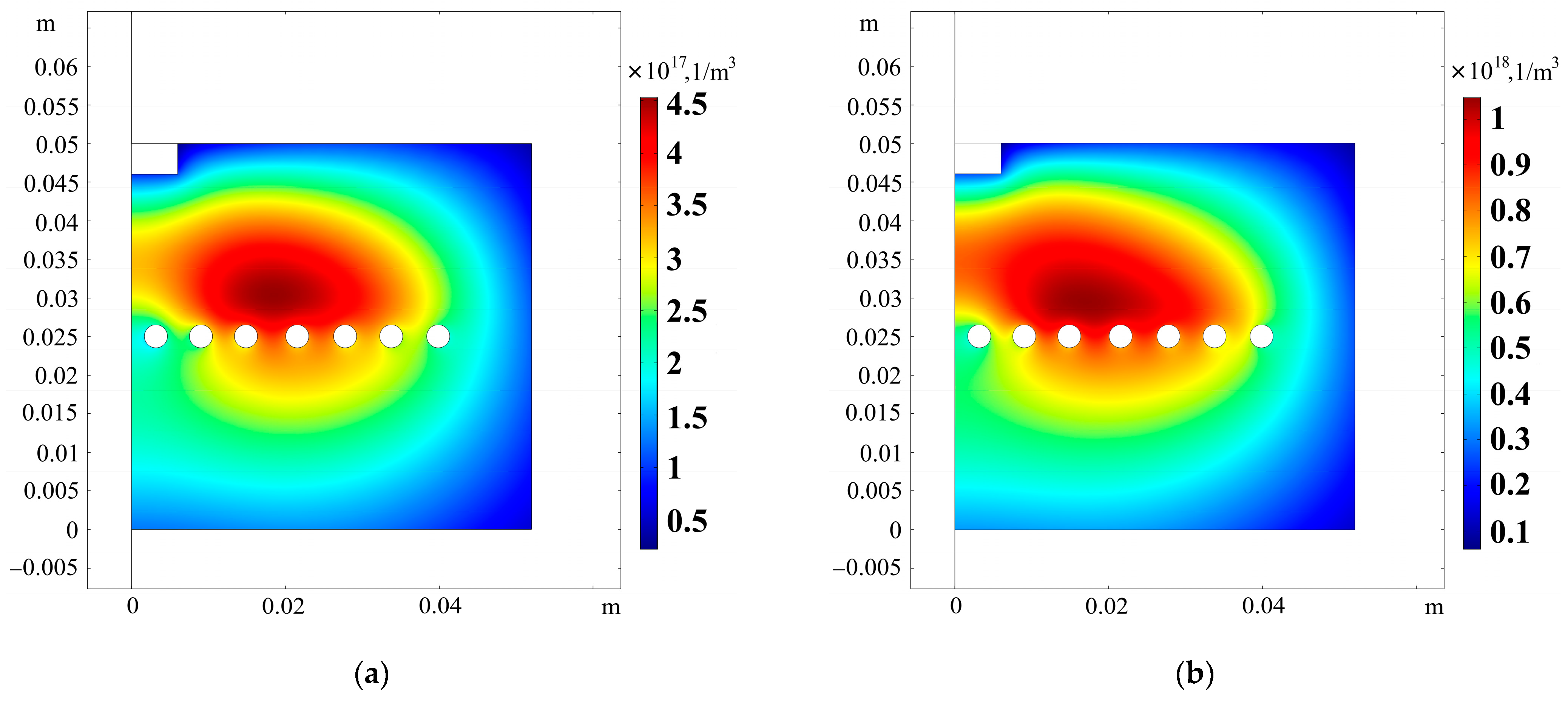
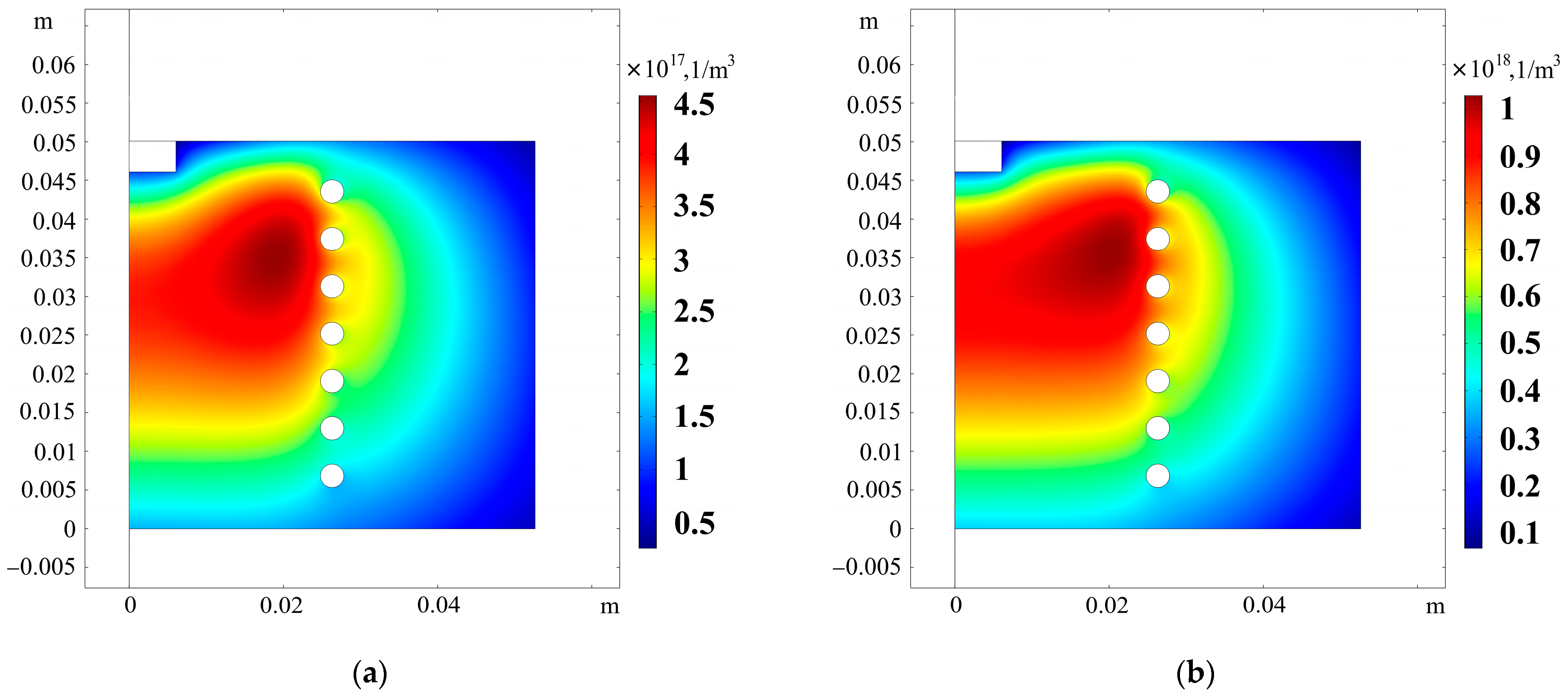
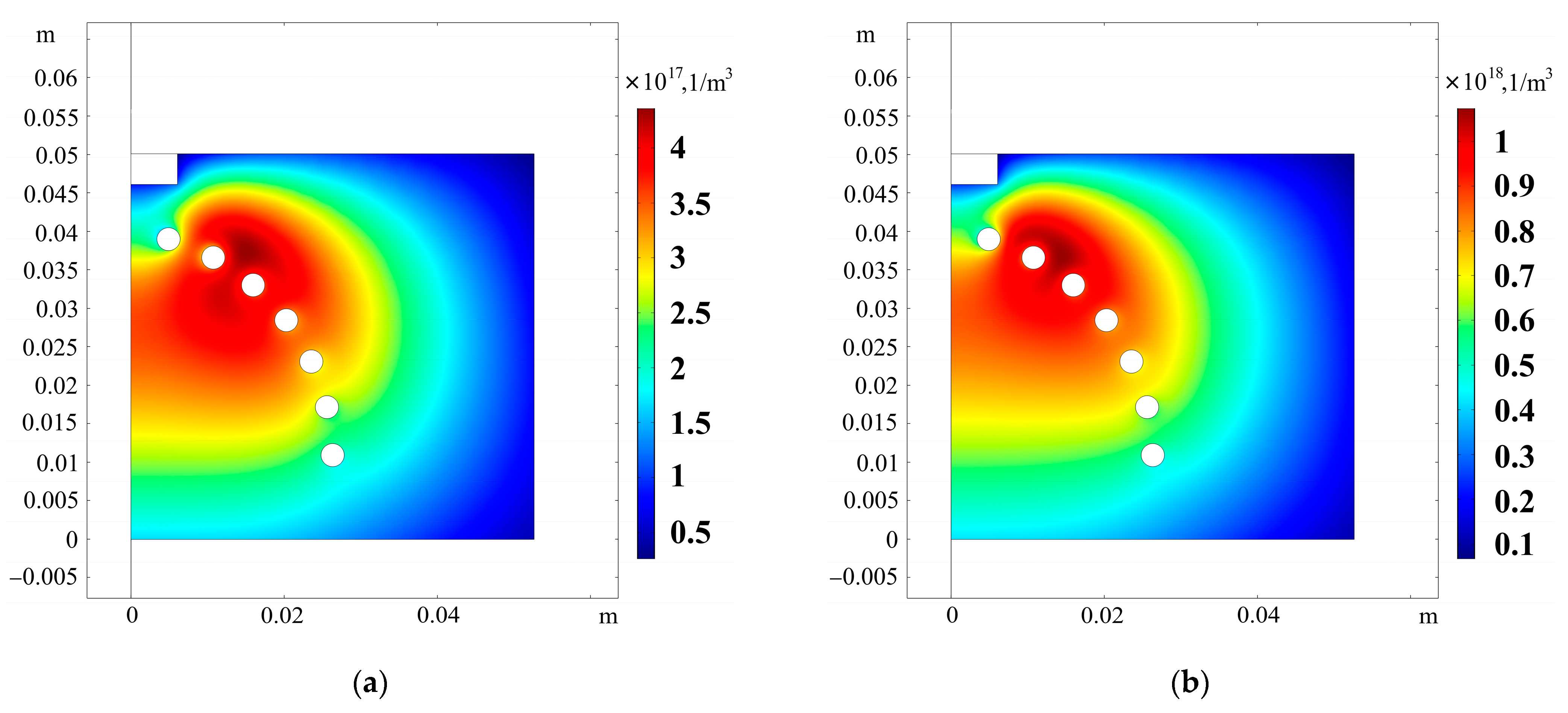
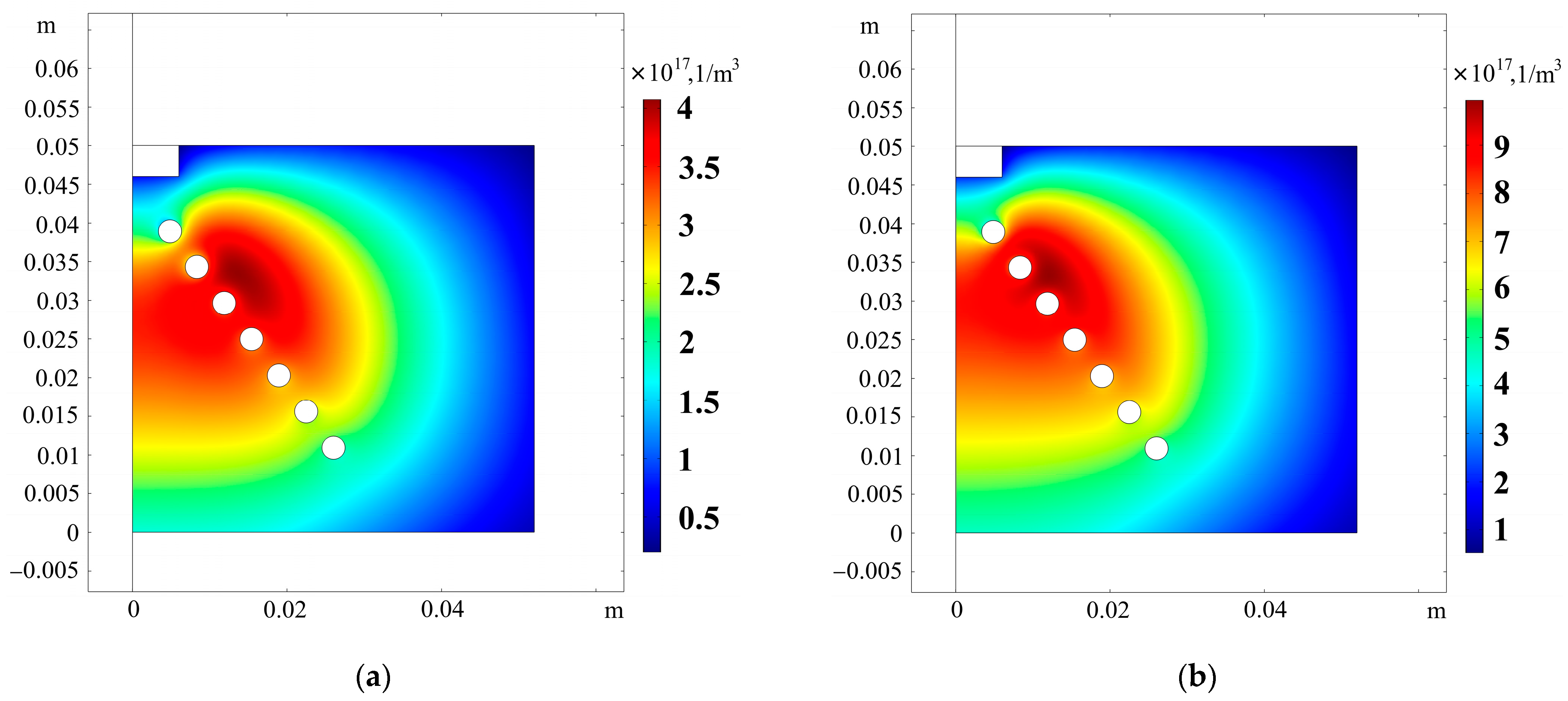
Analysis of the above dependences shows that any internal antenna configuration leads to a more efficient RF power input to plasma than an inductor located on the DC external surface. “The worst characteristics” were obtained with an external end antenna, partially due to the fact that for such a configuration, it is necessary to reduce the DC height, since in this case the most active ionization occurs in the region near its end surface (ref. to Figure 6). However, for a more correct comparison of various antenna options, the DC shape and dimensions were not changed in calculations. “The best characteristics” were observed when using an internal antenna with a conical arrangement of turns. In that case, the maximum efficiency improvement while ensuring the same extracted ion current was in the higher RF power region. When switching to operation mode with a lower extracted ion current, the positive effect decreased significantly and was practically within the error range of the calculation.
To better explain the reasons for the observed regularities,
Figure 5,
Figure 6,
Figure 7,
Figure 8,
Figure 9 and
Figure 10 show two-dimensional distributions of charged particle density for two operation modes (xenon flow rate of 0.5 mg/s, ion beam current of 140 mA; xenon flow rate of 1 mg/s, ion beam current of 300 mA) that were implemented in calculations using each of the considered antenna configurations.
According to the calculation results, the antenna configuration significantly affects the spatial distribution of the charged particle density in the RF plasma. The heterogeneity in the density of ions and electrons in its turn determines the radial distribution of the extracted ion current density and, consequently, the ion injector integral characteristics. For the side-by-side comparison of injector operation efficiency for each of the considered antenna configurations,
Table 1 contains the RF power necessary to provide the required extracted ion beam current (140 and 300 mA) at a fixed propellant flow rate (0.5 and 1 mg/s).
Analysis of the above data shows that the transition from the most commonly used external side antenna to the internal antenna with a conical arrangement of turns can halve the RF power consumption.
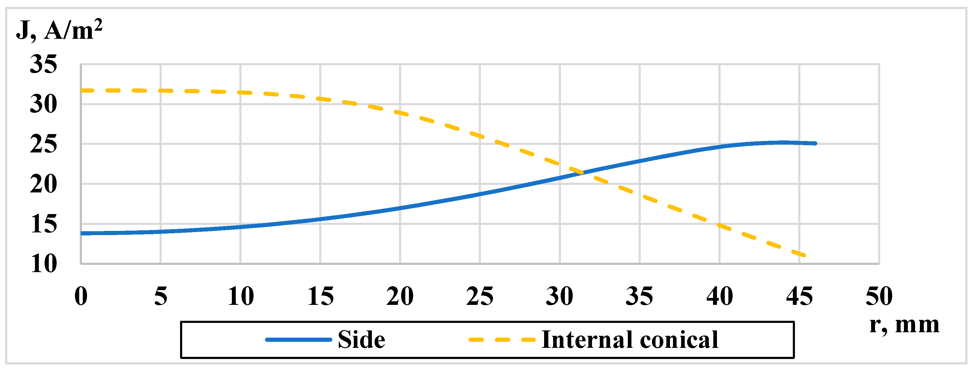
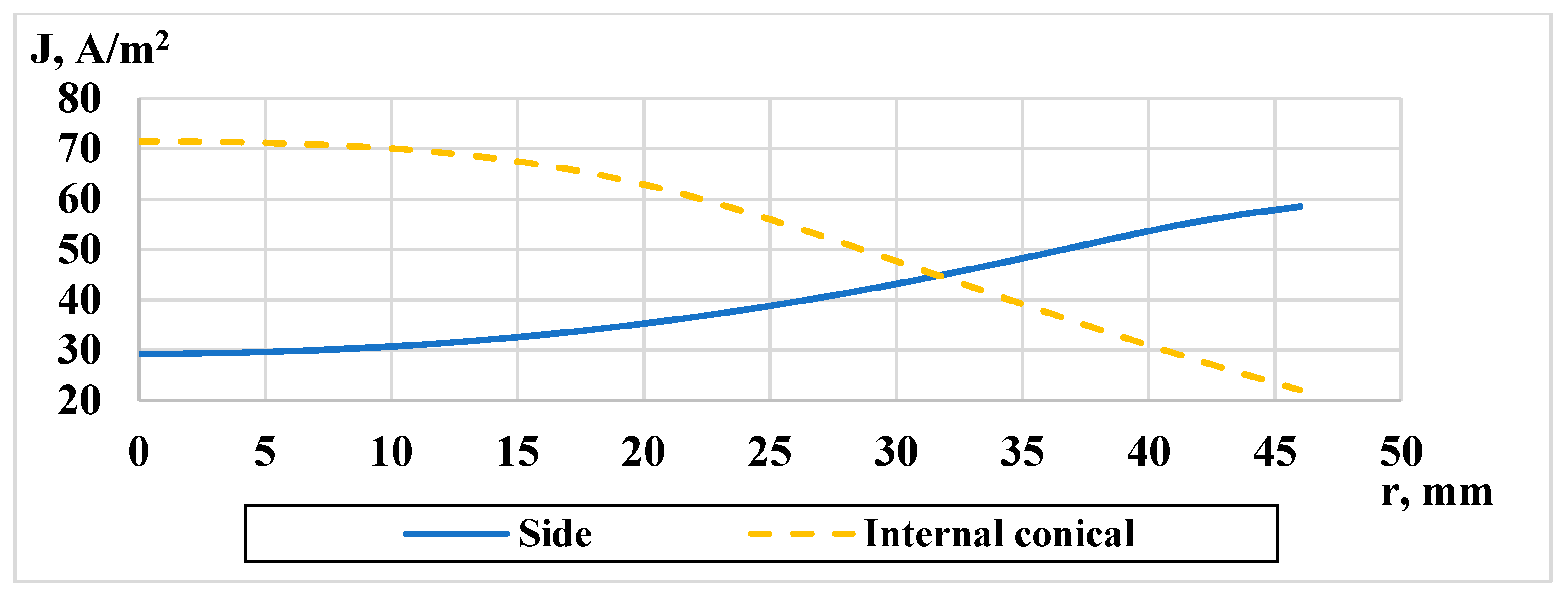
As noted earlier, the injector integral characteristics are affected by the ion current density radial distribution at the DC cross-section near the emission grid of the ion-extraction system. For comparison,
Figure 11 and
Figure 12 show the current density distributions obtained with the side antenna and internal antenna with a conical arrangement of turns, with which, according to the calculation, the injector operation efficiency is the highest.
Analysis of the above dependences shows that the use of an internal antenna leads to the maximum increase of the extracted ion current, if compared to the external lateral configuration of the antenna turns, and to its shift from the discharge chamber walls to the central region. Such a change in distribution allows us to predict an improvement in the RF ion injector integral characteristics.


