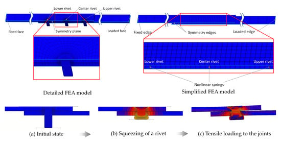
Article

A Simplified Finite Element Model of Riveted Joints for Structural Analyses with Consideration of Nonlinear Load-Transfer Characteristics

1
Department of Mechanical Systems Engineering, Aichi University of Technology, 50-2 Manori, Gamagori 443-0047, Aichi, Japan
2
Aeronautical Technology Directorate, Japan Aerospace Exploration Agency, 6-13-1, Osawa, Mitaka 181-0015, Tokyo, Japan
*
Author to whom correspondence should be addressed.
Aerospace 2021, 8(7), 196; https://doi.org/10.3390/aerospace8070196
Submission received: 5 June 2021 / Revised: 6 July 2021 / Accepted: 16 July 2021 / Published: 19 July 2021
(This article belongs to the Section Aeronautics)

Abstract

:
A simplified finite element model of riveted joints for structural analyses which effectively incorporates nonlinear response of riveted joints is proposed. Load-transfer characteristics of riveted joints were experimentally and numerically studied. First, a detailed finite element analysis for the process of a tensile test of a single-row joint which consists of squeezing of the rivet and tensile loading to the joint was conducted to confirm the validity of a conventional method of analysis. The load–relative displacement behaviors of single-row joints observed in the detailed finite element analysis and previously conducted experiments agreed well. Then, a simplified method of the analysis was developed based on the detailed analysis and the experiments and was applied to analyses of multiple-row joints. A nonlinear relationship between load and relative displacement in the simplified analyses had good agreement with the detailed one. Distributed loads to the multiple rivets in the simplified analysis coincided with those of the detailed analysis under the maximum load. Memory and CPU time required to run the simplified analyses were reduced to about 1/4 and 1/6 compared to those of the detailed analysis, respectively.

Graphical Abstract

1. Introduction

In the structural design of an aircraft, damage tolerance is required to be carefully considered to ensure structural integrity under service conditions. Numerical analyses are widely utilized to evaluate the structural integrity to meet the requirements. As it is difficult to directly analyze the effect of damage in a component of the structure on the whole aircraft in terms of computational costs, multiple analyses for different scales of the structure are generally conducted, as shown in Figure 1. The nonlinear response of the structures, such as buckling, plasticity, effect of damage, etc., is usually considered in the analysis with a lower scale due to the limitation of computational costs [1,2,3,4,5,6,7,8].
As loads in components of aircraft structures are mainly transferred through joints such as rivets under complex service conditions, the rivet is a potential origin of damage [9,10,11]. Therefore, it is important to incorporate characteristics of the rivet joints in the analysis of damage-tolerant structures. When the effect of multiple damages in different components on the whole aircraft structure is considered, a nonlinear response of the rivets is desired to be incorporated into analyses in the higher scale of the structure.
However, a method that can express the nonlinear load-transfer response of riveted joints in large-scale structures in an effective way in terms of accuracy and computational costs has not yet been proposed as of the time of writing [12,13,14,15,16,17,18,19,20,21,22]. In this study, we propose a method where the nonlinear response of riveted joints is accurately expressed with a low computational cost.

2. Definition of Loads Transferred through Rivet Joints

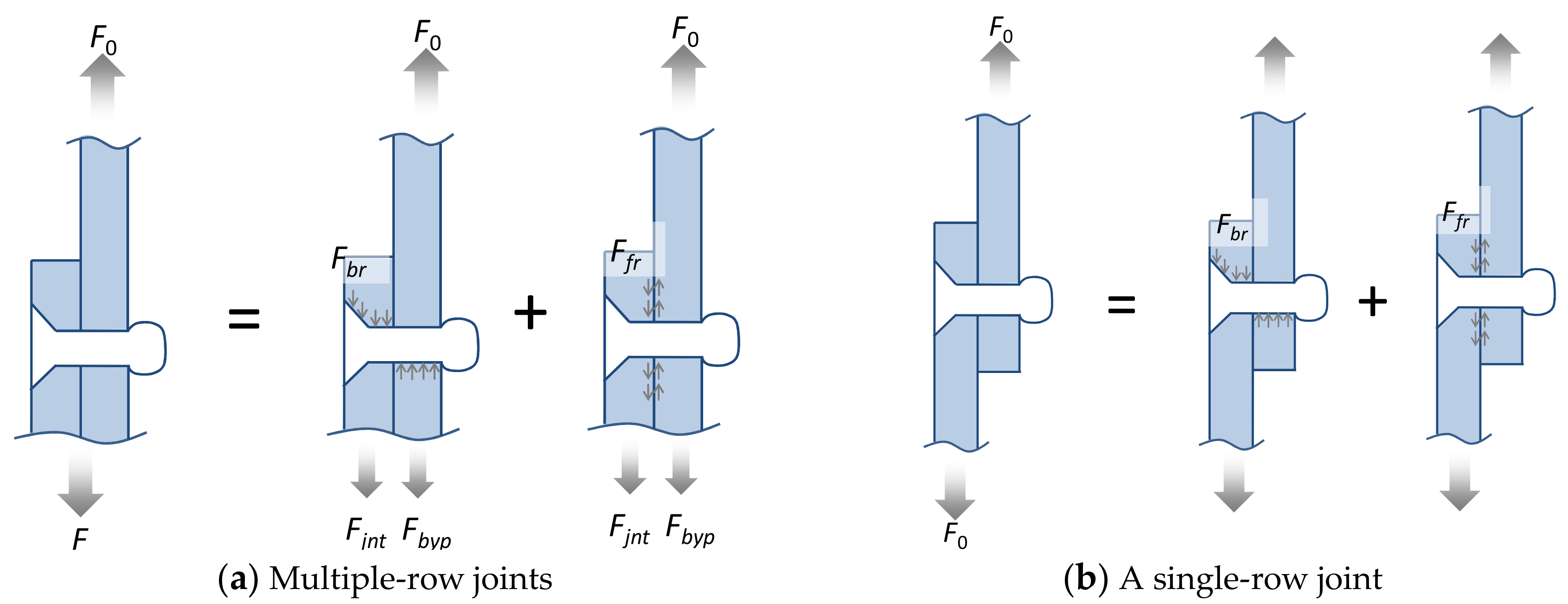
Huth proposed that loads transferred through a riveted joint can be expressed in the following equation [23].
F 0 = F j n t + F b y p = F b r + F f r + F b y p
where F0 shows total load in the joint and Fjnt and Fbyp show load transferred through the joint and load bypassed to the plates. Fjint has two parts, where Fbr, Ffr, are bearing load between rivets and holes and frictional load between fastened plates, as shown in Figure 2a. In the case of a single-row joint, as shown in Figure 2b, the relationship can be written in a simple form as follows because of the lack of the bypassed load.
F 0 = F b r + F f r
In this study, the above relationship is adopted to evaluate the transferred load.
Although it is difficult to experimentally evaluate Ffr for a fastened plate, it can be evaluated in a finite element analysis by the Coulomb friction law using the following equation.
F f r = i = 1 n n o d e μ F n i
where μ is a coefficient of friction and Fni is the contact reaction force normal to the plates at the ith node.

3. Experiment

3.1. Experimental Set Up

Tensile tests were conducted to evaluate the relationship between the load and relative displacement of riveted joints [24]. Equipment and specimens used in the experiments are shown in Figure 3a,b, respectively. Two plates of 2024-T3 aluminum alloy with a thickness of 1.8 mm were cut into pieces with dimensions of 20 mm × 60 mm and fastened by a single lap joint with an MS20426AD countersunk rivet with a diameter of φ 3.2 mm. The squeezing force Fsq of rivets was set to a small value of 13 kN since we aimed to evaluate load-transfer characteristics without effects of frictional force in this study. A small LSC-2kN desktop test machine (Tokyo Experimental Equipment, Co., Tokyo, Japan) was used for the experiments. A tensile load of 2 kN was applied with a cross-head speed of 1.0 mm/min.
A Strainscope noncontact measurement system (JT Toshi, Co., Tokyo, Japan) was used to evaluate relative displacement of the joints. In this system, relative displacement between 2 measuring points previously marked on the specimen were consecutively measured based on images from a digital camera. The specimens were painted white and black markers were attached to the specimen with a distance of 50 mm, as shown in Figure 3b. Nominal strain can be automatically calculated in this system by dividing the original distance by the relative displacement when the material and its cross-section are uniform between the 2 measuring points. In our case, the relative displacement between the markers was only obtained because of nonuniformity of the cross-section.

3.2. Results and Discussion

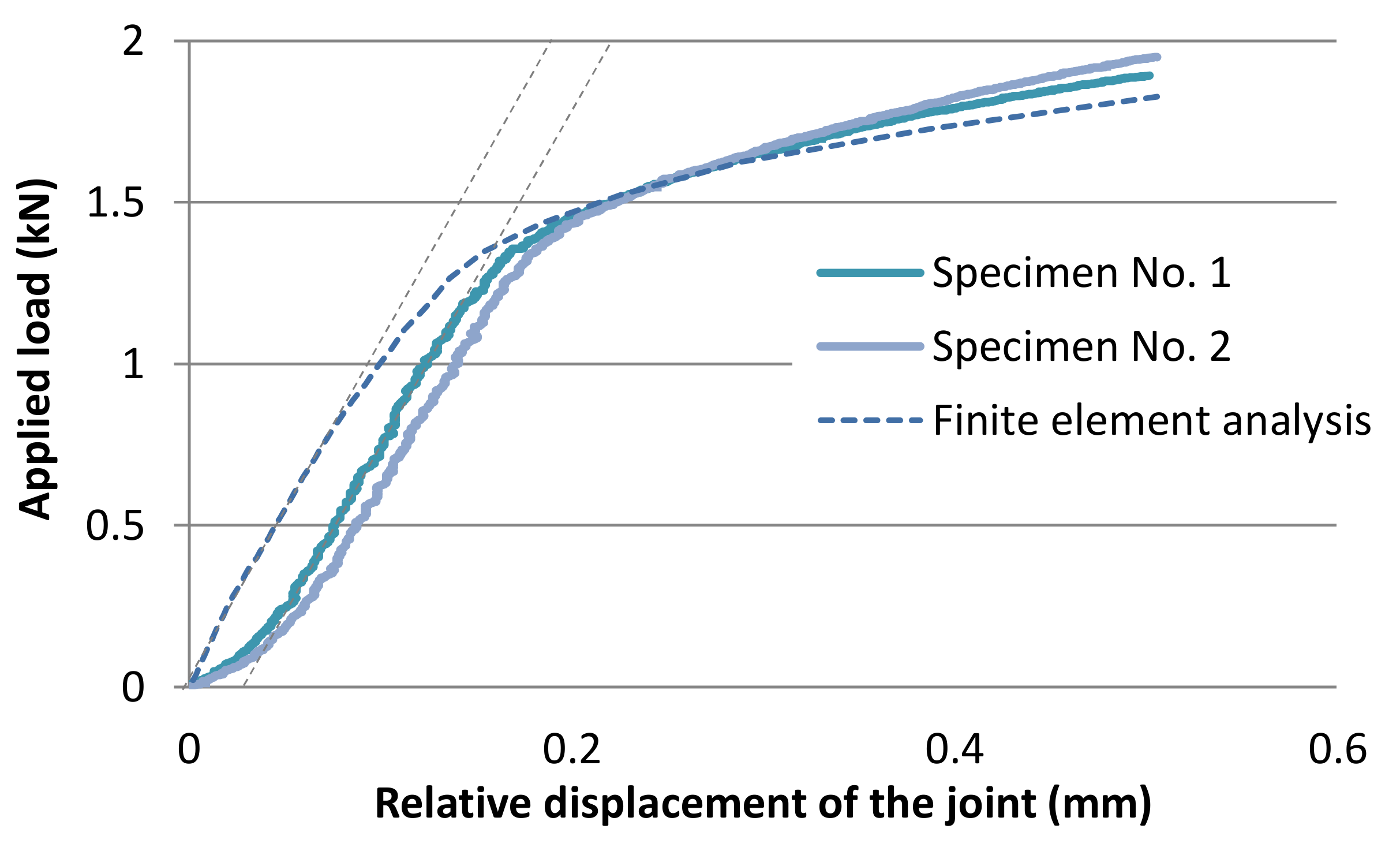
Relationships between applied loads and relative displacements obtained from the experiments are shown in Figure 4. Two solid lines show the experimental results, where the two curves are almost coincident with each other. The results shown with dashed lines are discussed in Section 4. At the initial stage of the experiment, a nonlinear relationship between the load and relative displacement is observed. This is considered to be mainly caused by a difference in the neutral axes of two fastened plates and initial clearance between the rivet and hole. After that, the load increases linearly with the relative displacement until the load reaches about 1.3 kN. The stiffness of the specimen decreases with the further increase in the load. Due to a lack of frictional force, it is considered that the stiffness reduction is mainly caused by plastic deformation in the vicinity of rivets.

4. Finite Element Analysis of a Single-Row Rivet

4.1. Analytical Model

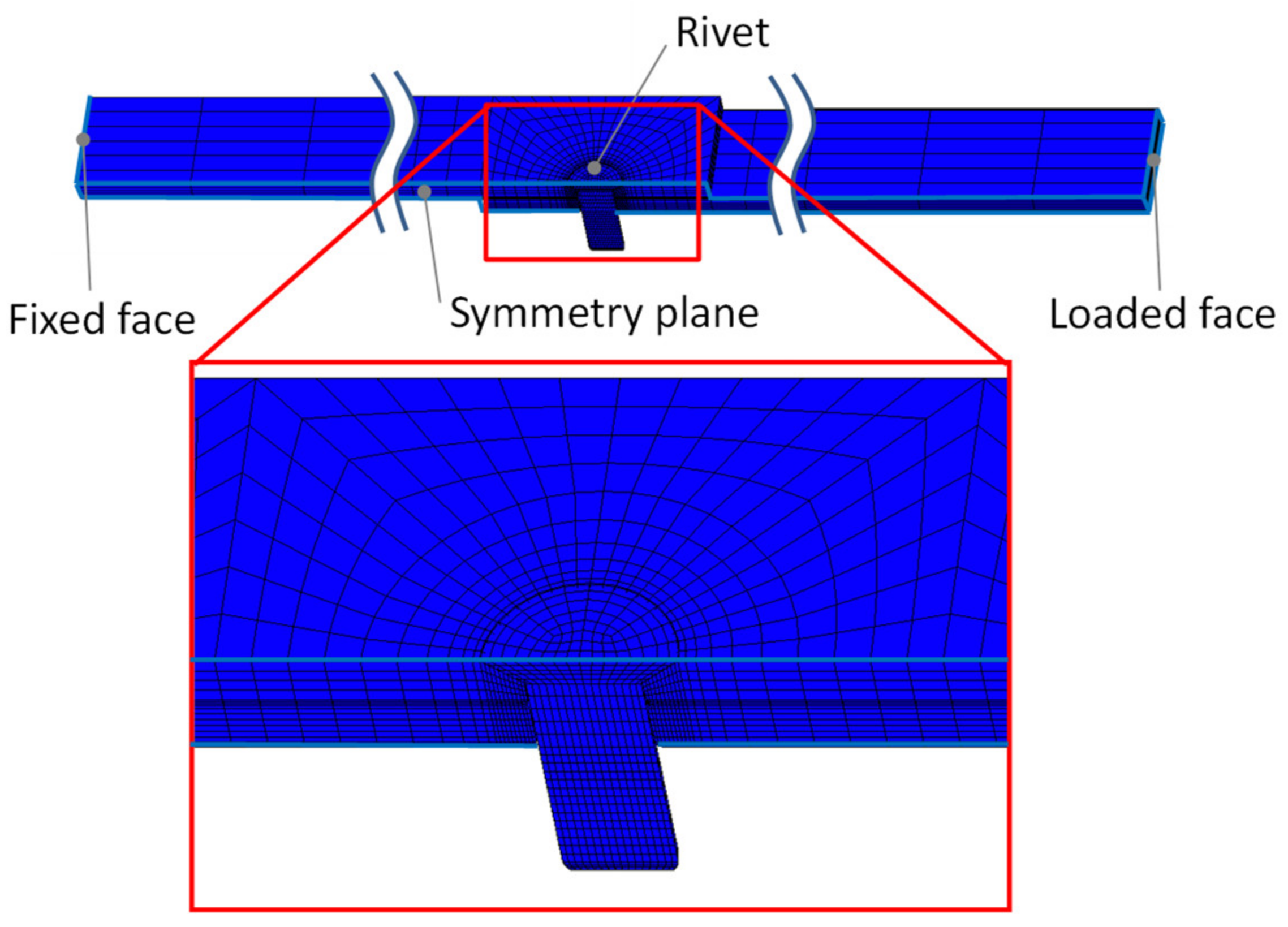
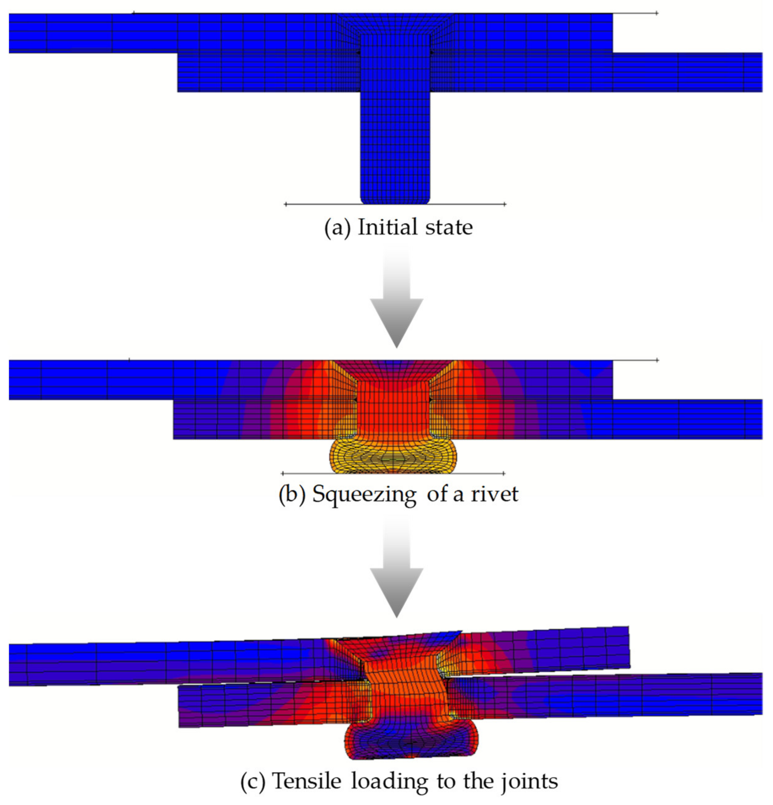
Li demonstrated that the load–relative displacement relationship and strain distribution around holes of specimens during tensile tests can be precisely analyzed by nonlinear finite element analyses with an elastic–plastic material model and continuum elements [25]. Nonlinear load-transfer characteristics of riveted joints were analyzed in a similar manner in this study [26]. Marc and Mentat 2017 (MSC Software Co.) were used as a solver and pre-post software of the finite element analyses. Eight-node hexahedral reduced-integration elements (Type 117) were used to avoid volumetric locking due to excessive plastic deformation. The half model was developed based on symmetry in the lateral direction of the specimen. The analytical model and material properties used for the analyses are shown in Figure 5 and Table 1, respectively. Specifications of hardware used for the analyses are shown in Table 2. Processes from squeezing of a rivet to the application of tensile load were sequentially analyzed with consideration of contact conditions of each part and large strain due to plastic deformation, as shown in Figure 6. The Coulomb friction law was adopted and the coefficient of friction μ was set to 0.2.

4.2. Results and Discussion

The relationship between applied load and relative displacement obtained from the finite element analysis with 13 kN of squeezing force is shown as a dashed line in Figure 4. At the stage where the load–displacement curve is linear, stiffness of the joint in the experiment and the analysis are nearly coincident. The curves also demonstrated that stiffness starts to decrease with a similar level of the load in the two results.
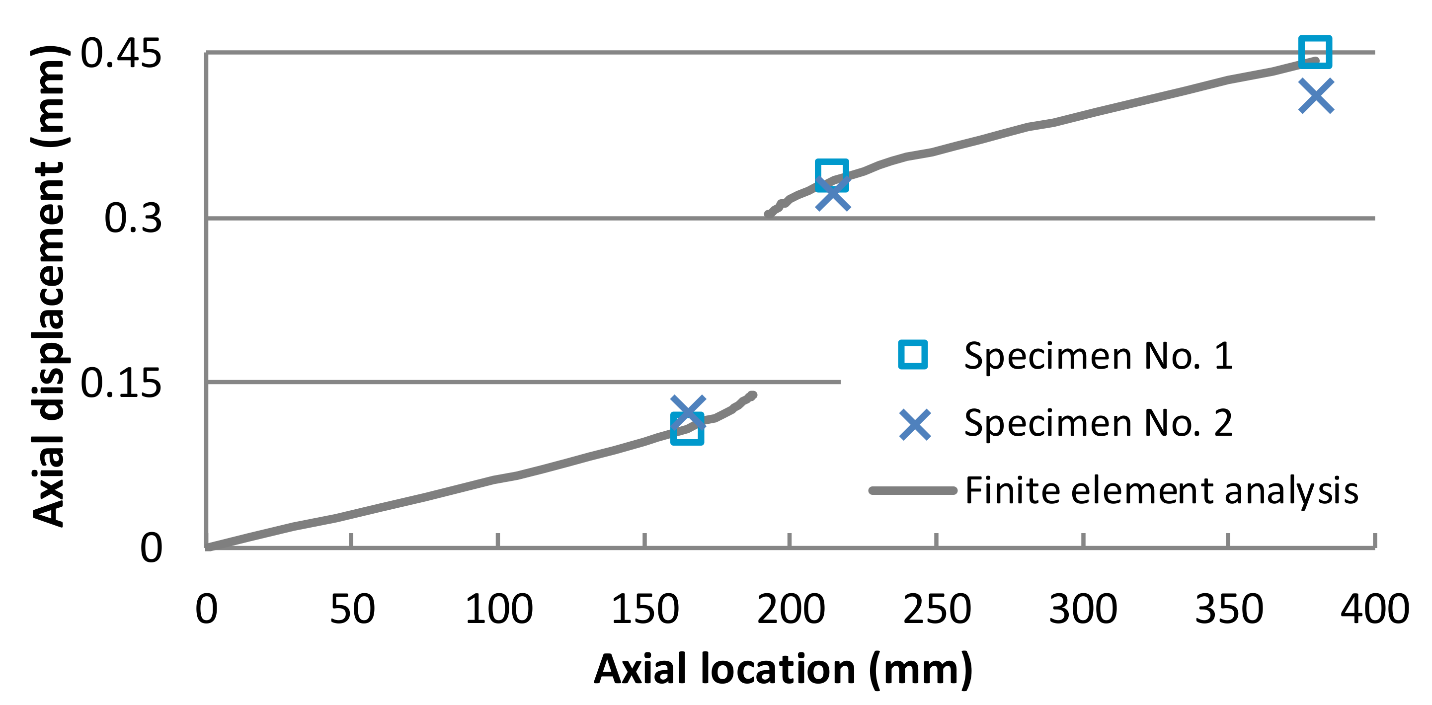
Figure 7 shows axial displacement along the center line of the specimen with 1.5 kN of applied load. The vertical axis shows the displacement, and the horizontal axis shows the location along the center line. The distribution of displacement in the analysis is shown as a gray line. Displacements at two measurement points and the cross-head of the testing machine are plotted for the experimental results due to the limitation of the measurement system. The distribution shows that deformation is especially large around the rivet. At the upper and lower measuring points in the experiment, the displacements in the analytical and experimental results agreed well.
These agreements of the load–relative displacement relationships indicate the feasibility of the analytical model developed in this section.
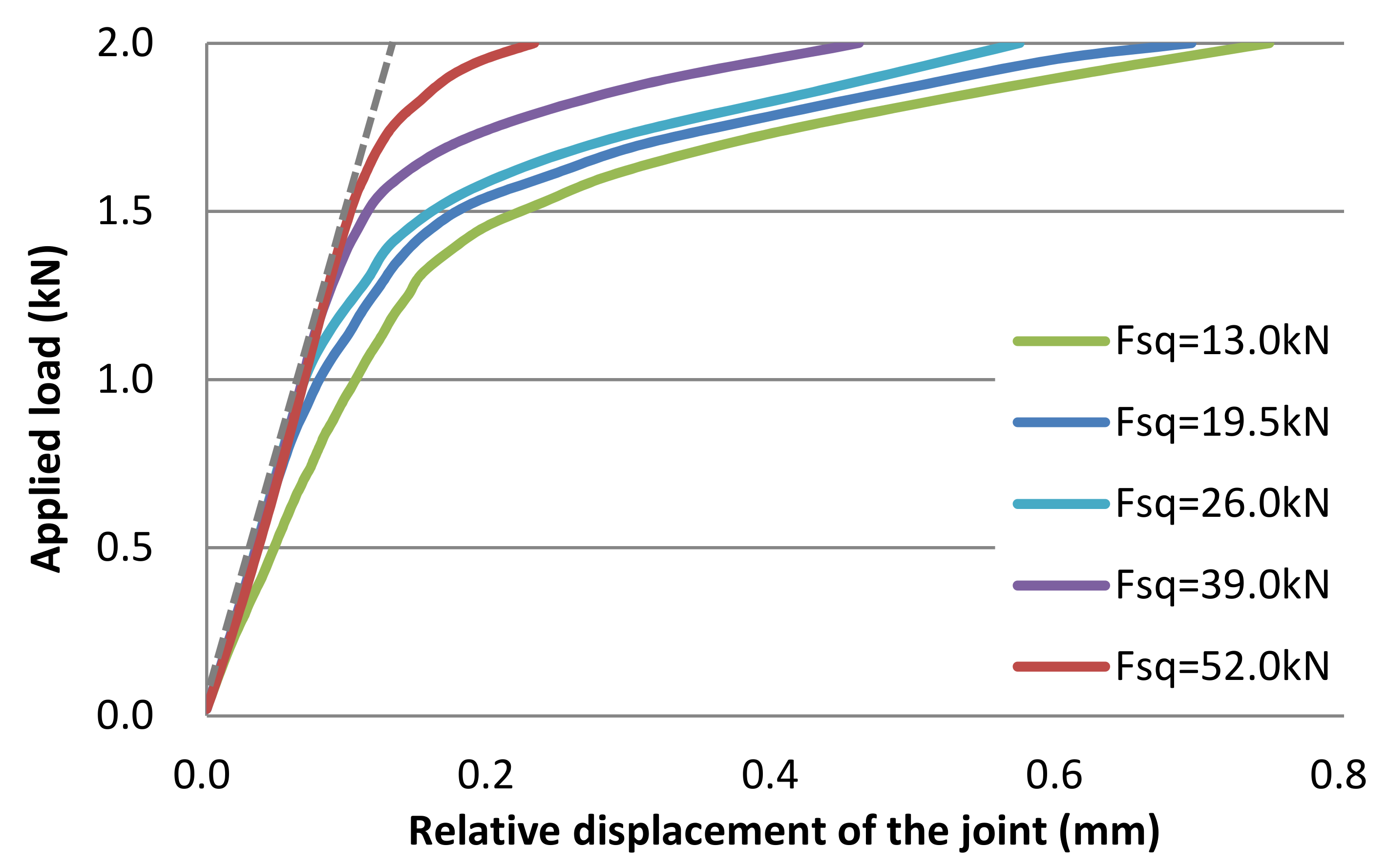
Variations in the load–relative displacement curve with a squeezing force Fsq ranging from 13 to 52 kN are shown in Figure 8. At the initial stage in all cases, there are linear regions of the load–relative displacement relationships where elastic deformation is dominant. The stiffness starts to decrease with further increases in the loads due to slip under further loads larger than the frictional force and plastic deformation of the joint. The larger squeezing force applied to the rivet, the larger load the stiffness reduction of the joint starts with.
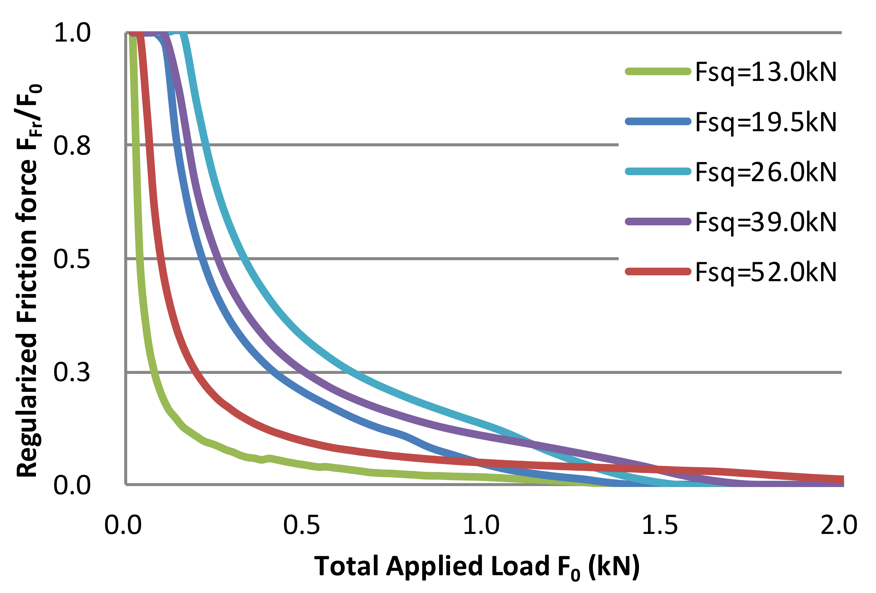
In order to study the effect of friction on the relationship between the load and relative displacement, frictional force Ffr was evaluated by using Equation (3). Frictional force Ffr was regularized by total applied load to the joint, as shown in Figure 9. In the initial stage when the total applied load is small, the frictional force accounts for a large percentage of the total applied load. With a further increase in the total applied load, the effect of the frictional force decreases and it ultimately becomes almost zero. Due to the difference in the axis of the applied load and neutral axes of the plates, out-of-plane deformation of the plates increases with the increase in the applied load, and finally the applied load is transferred in the direction that separates the plates. This behavior can be seen in Figure 6c. The effect of friction does not monotonically increase with the increase in the squeezing force Fsq. This is considered to be due to reduction in the contact surface caused by local deformation of the plates near the rivets in the squeezing process with 39 kN of squeezing force Fsq or more.
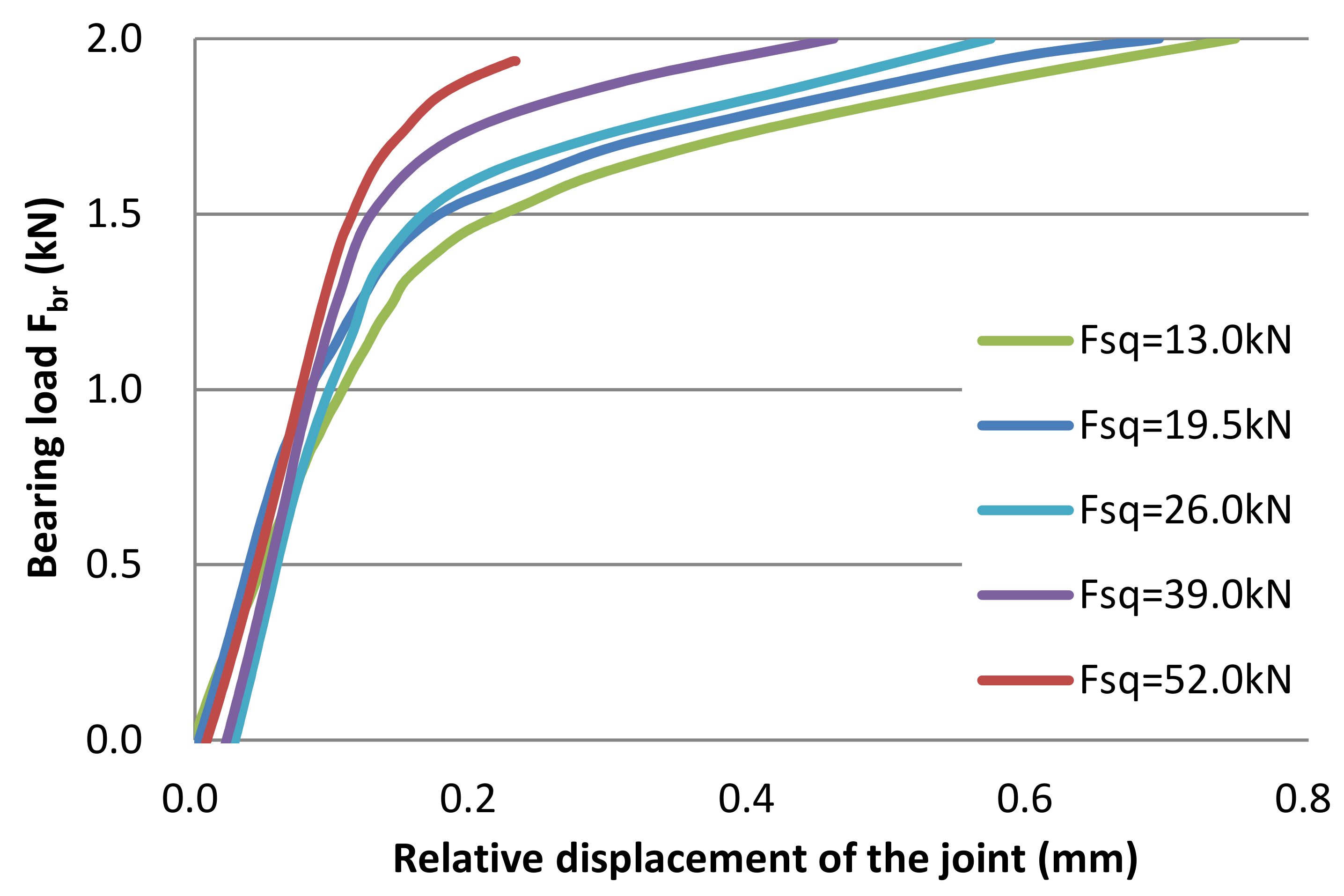
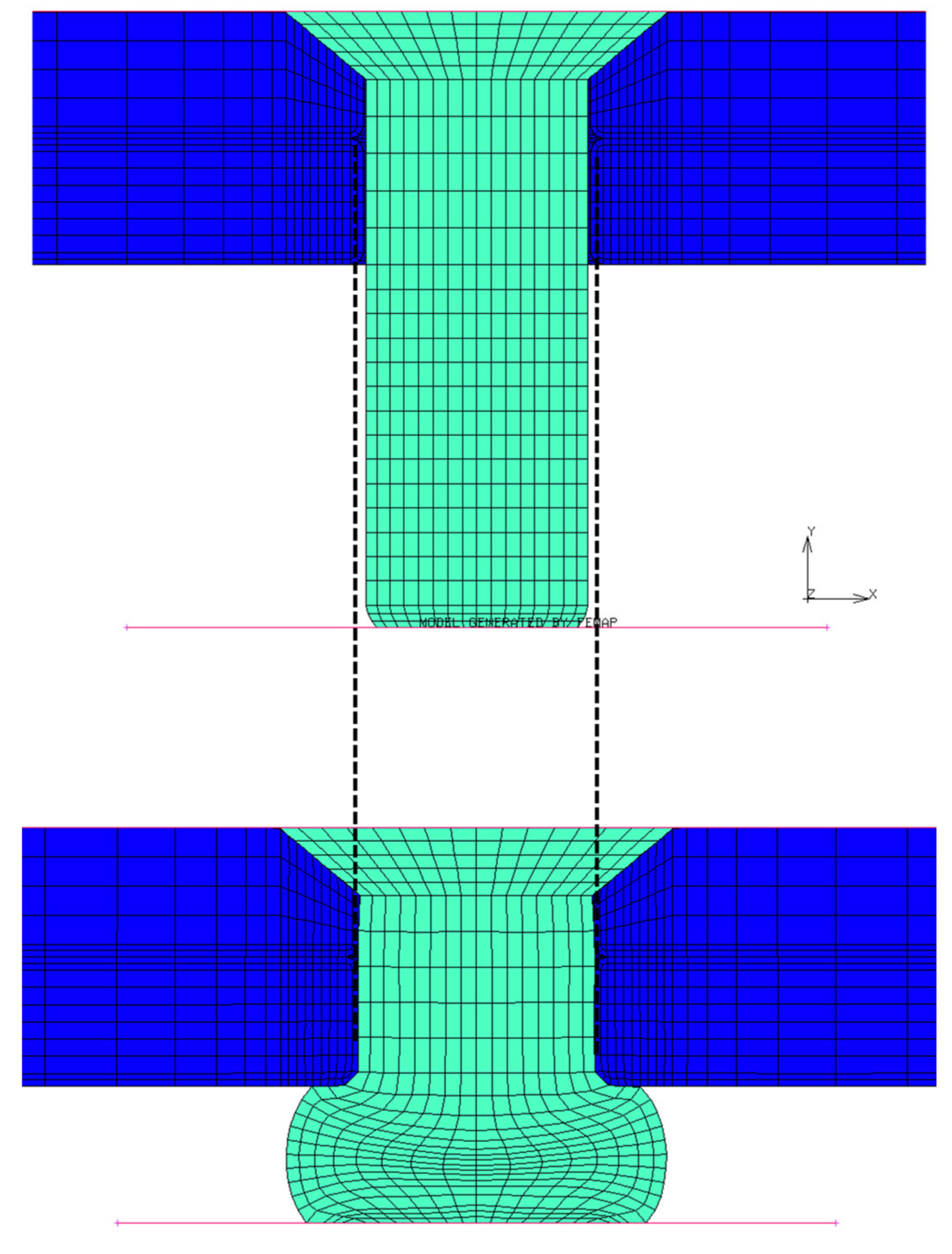
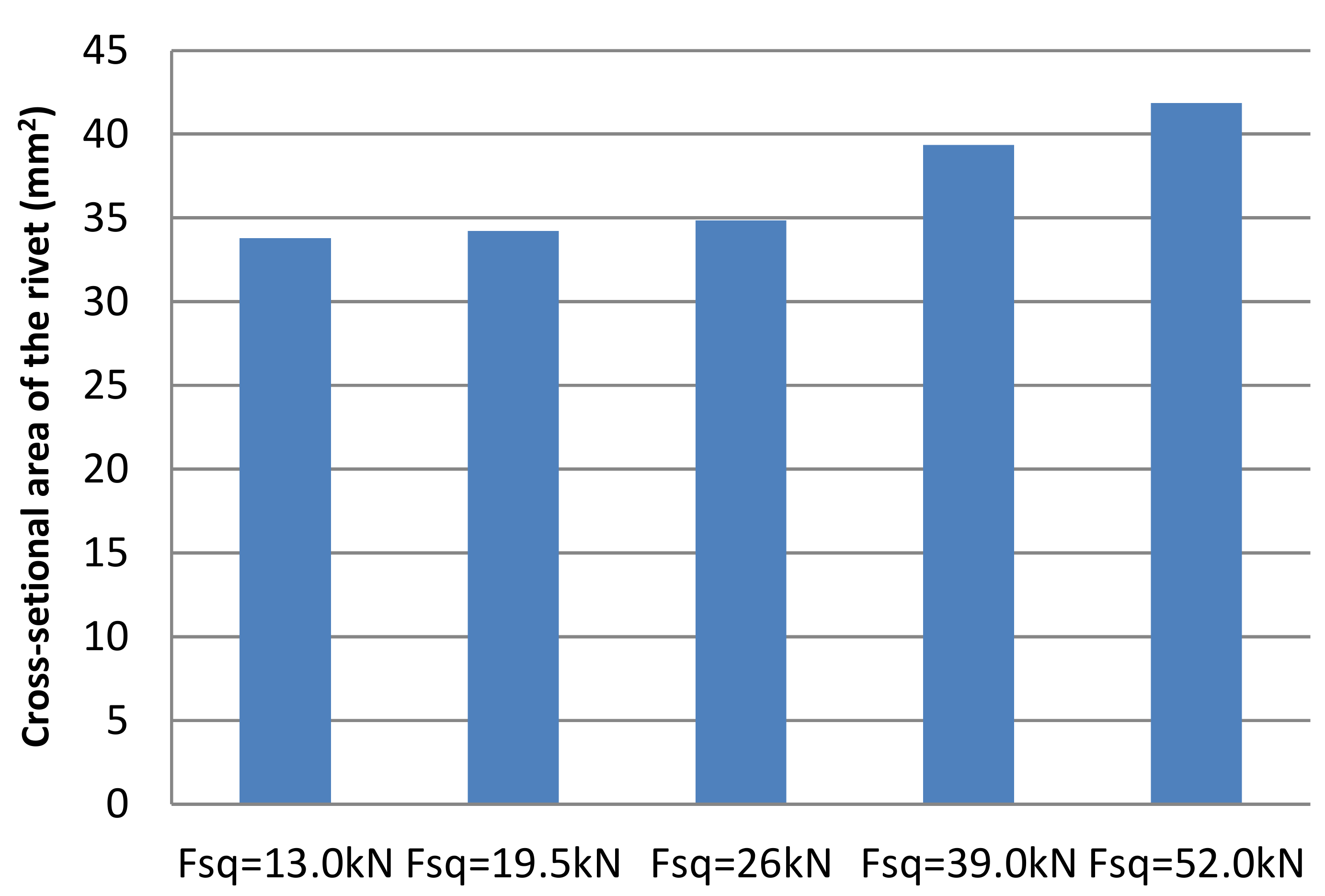
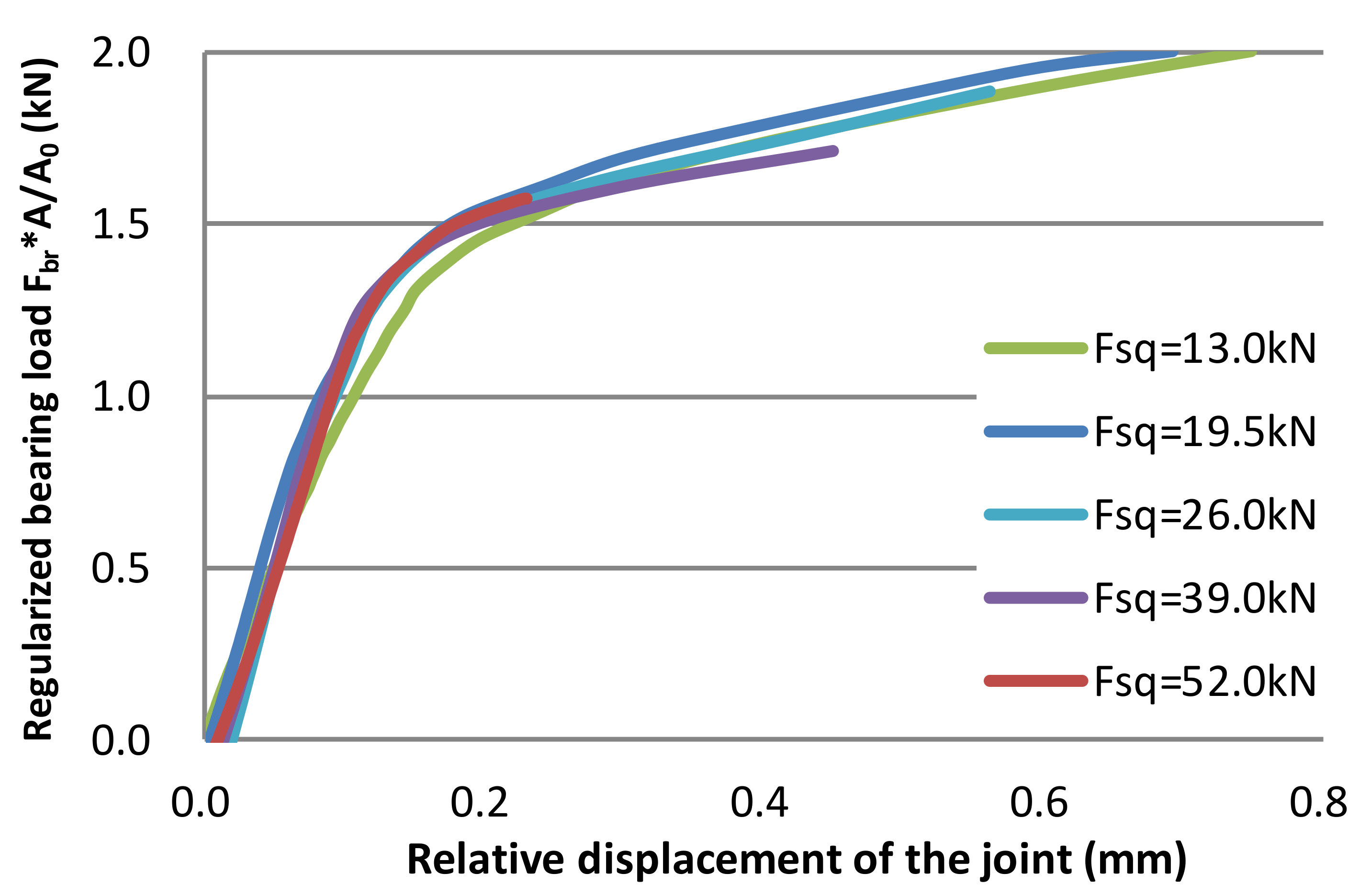
Bearing load Fbr was evaluated by substituting the total load F0 and frictional load Ffr into Equation (2), as shown in Figure 10. Each curve shows similar trends, although the bearing load required to start the stiffness reduction increases with squeezing force Fsq. Figure 11 shows that the cross-sectional area of the rivet shank increases in the squeezing process. We focused on this behavior for further investigations of the trend. Figure 12 shows that the cross-sectional area of the rivet shank immediately after the application of squeezing force Fsq. As shown in Figure 13, the curves of bearing force Fbr were regularized by a ratio of variation of the cross-sectional area A0/A where A0 and A are cross-sectional areas before and after the squeezing process, respectively. As the regularized curves are nearly coincident, an increase in the cross-sectional area of the rivet shank with squeezing force Fsq has a dominant effect on the increase in the bearing load Fbr.
The maximum amount of computational resources required to run these analyses was about 850 MB of memory and 8300 s of CPU time.

5. Finite Element Analysis of Multiple-Row Riveted Joints

5.1. Analytical Model

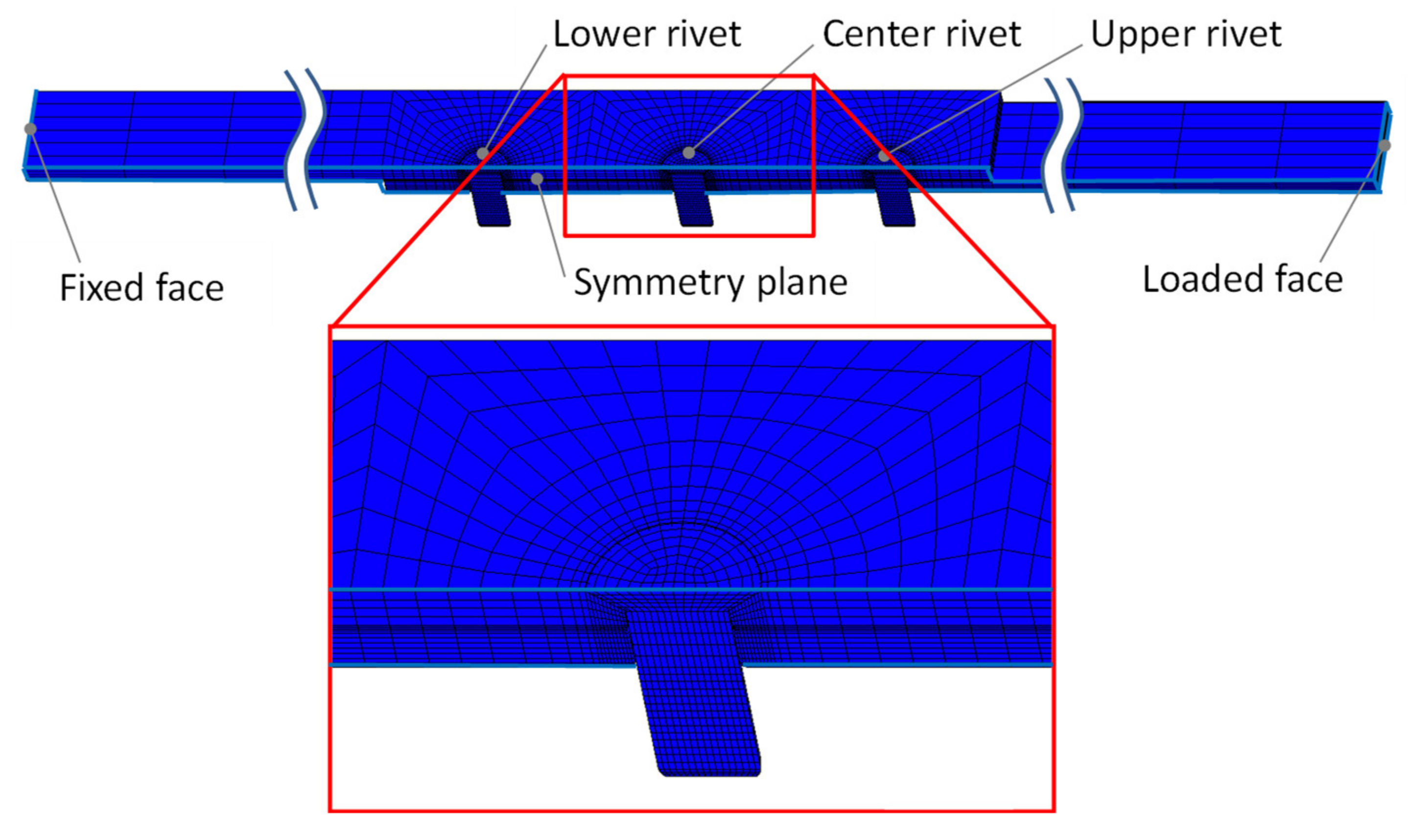
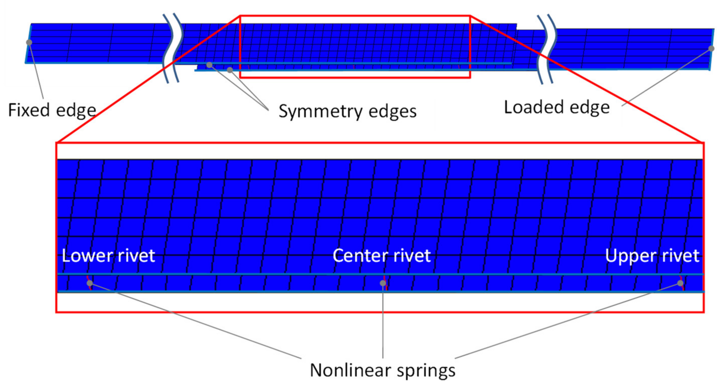
A simplified model for multiple-row riveted joints, which is usually adopted in real aircraft structures, was developed. First, triple-row riveted joints were precisely analyzed by the same method presented in the previous section to evaluate loads distributed to each rivet, as shown in Figure 14. Next, the simplified model of the triple-row joint with the same boundary conditions as the detailed model was developed and its results were compared to that of the detailed analysis to confirm the effectiveness of the simplified model. In the simplified model, the plates were modeled with a four-node thick shell element (Type 75), as shown in Figure 15.
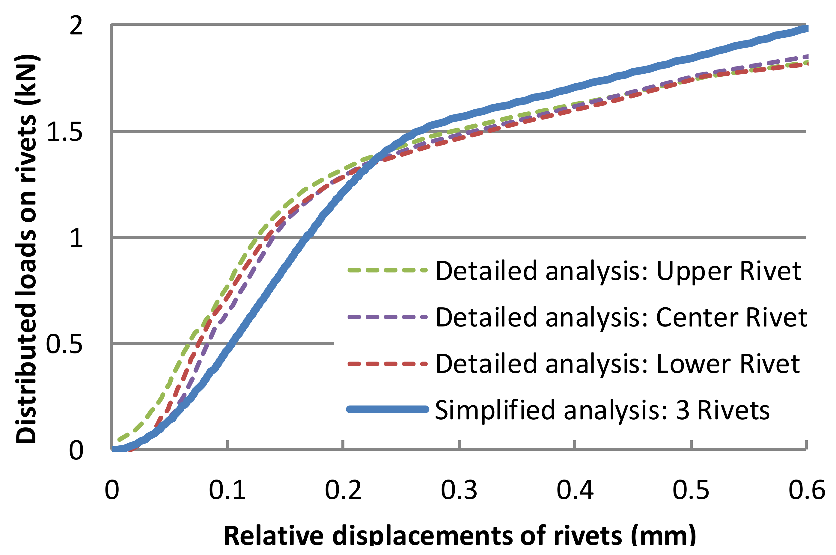
The rivets were modeled with a nonlinear spring element connected to nodes located in the center of each rivet. The relationship between shear load and relative displacement of the nonlinear springs was defined in the following way. In Figure 16, the load–relative displacement and the stiffness of the springs are shown as blue and red lines, respectively. As shown with the last two points of the blue line, slopes of the load–relative displacement curve were calculated by dividing the load increment between two consecutive points by the corresponding displacement increment using Microsoft Excel. These consecutive data express the stiffness as a function of the relative displacement, as shown with the red curve. This curve became a stepwise function because the stiffness between two points in the load–displacement curve is constant. The stiffness of nonlinear springs for the simplified analyses was defined with these data.
There are scatters of the stiffness observed in a region where the relative displacement is small. They are numerically caused when the detailed analysis faced severe nonlinearity, such as plasticity and a change in contact conditions, especially in the vicinity of the rivet hole. The time step of the analysis was automatically adjusted to overcome the difficulty of convergence of the nonlinear solution, which resulted in a change in the slope of the load–relative displacement relations. The moving average of the stiffness is shown as a dashed line for reference. The scatter was about 10% and did not have a significant effect on the result of the carried load in the simplified analysis, as shown in the next section.
As shown with the curves in Figure 13, the relationship for the nonlinear springs can be derived for any case of squeezing force Fsq without many experiments by regularizing one curve by calculated the cross-sectional area of the rivet shank after squeezing.

5.2. Results and Discussion

Figure 17 shows a comparison of load–relative displacement curves from the detailed and simplified analyses. Stiffness in the simplified analysis is found to be lower than that of the detailed analysis. Deformation of the rivet shank can be taken into account in the detailed analysis, but on the other hand it is not expressed by the nonlinear springs in the simplified model, which is considered to be the reason for the difference in the stiffness. The stiffness decreases with the further increase in the load and eventually reaches the same level in both analyses. The difference between ultimately transferred loads in the detailed and simplified analyses is about 7.5%.
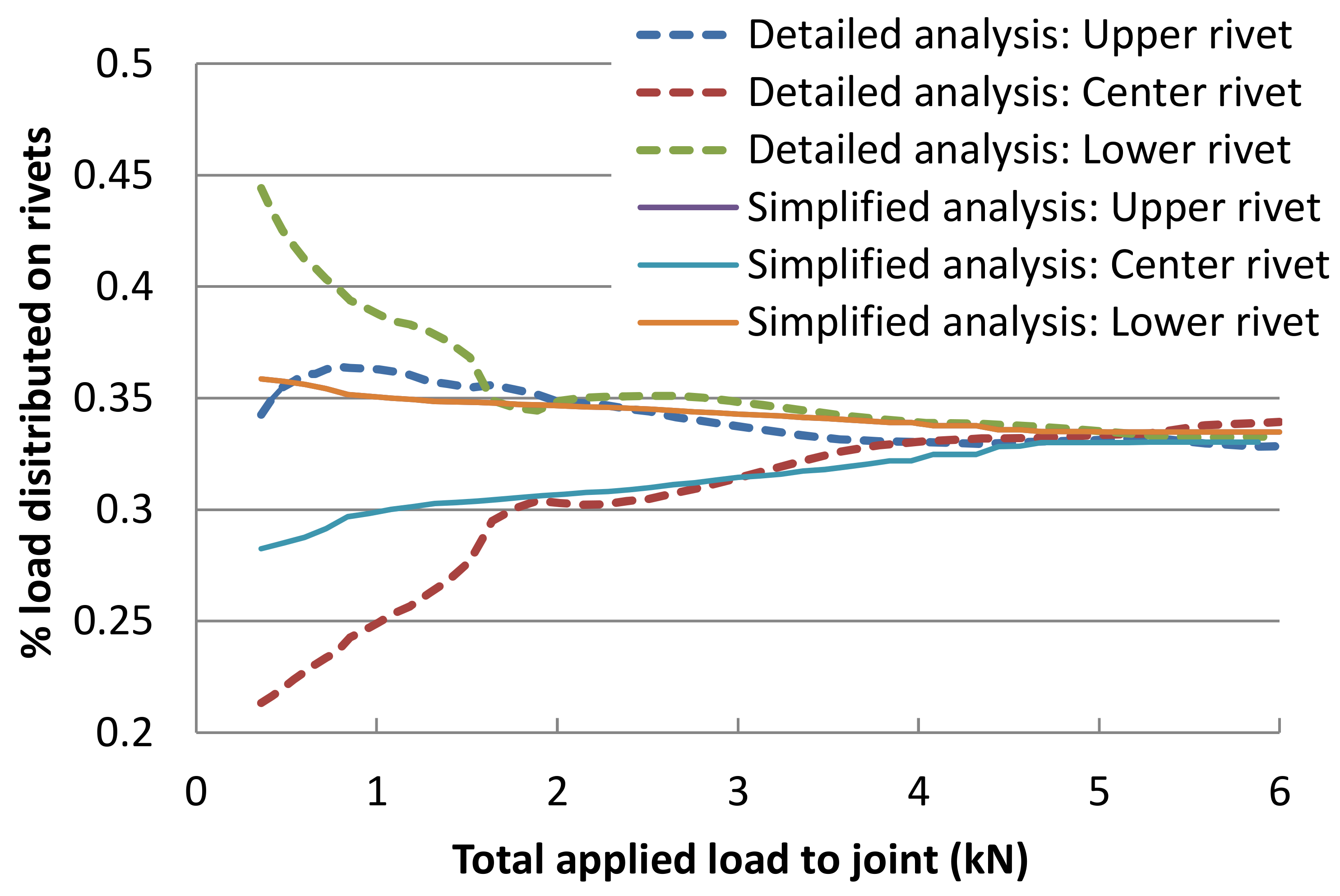
The ratio of the distributed loads to each rivet to the total applied load was evaluated as shown in Figure 18. The change in the ratio and the total applied load are plotted on the vertical and horizontal axes, respectively. A dashed line shows the result from the detailed analysis and a solid line shows the results from the simplified analyses.
In the detailed analysis, loads that the upper and lower rivets bear are higher than that of the center rivet in the initial stage. The ratio of the distributed loads to the rivets changes with further loading, and the ratio for all rivets reach almost the same level in the end. The initial difference in loads in the upper and lower rivets are considered to be due to asymmetry in the thickness direction of the plates, attributed to asymmetry of the countersunk rivets and residual stress in the squeezing process of the rivets. In the simplified analysis, where the aforementioned factors are not considered, the distributed loads to the upper and lower rivets are coincident through the analyses, as shown with two overlapped lines in Figure 17.
In both the simplified and detailed analyses, the initial ratios of distributed loads to the upper and lower rivets are larger than that of the central rivet. The difference in the distributed load decreases with the increase in the applied load and it ultimately vanished. This trend has been observed in riveted joints in practical use [25] but cannot be expressed by a conventional method of finite element analysis where rivets are modeled as linear elastic materials. Under conditions where the total applied load is about 2 kN or more, ratios of distributed loads to each rivet are almost same for the results in the detailed and simplified analyses. Under the loading conditions in the presented analyses, shear stress in each rivet is about 80 MPa and lower than 180 MPa, which is the strength of the adopted rivets. This indicates that the present loading condition fits the practical use of riveted joints in aircraft structures.
Computational resources were greatly reduced in the simplified analysis compared to the detailed analysis. Memory required for the detailed and simplified analyses was about 1700 MBytes and 370 Mbytes, respectively. Elapsed CPU times were 13,000 s for the detailed analysis and 2100 s for the simplified analysis. Required memory in the simplified analysis decreased to about 1/4 of the detailed analysis, and CPU time in the simplified analysis was reduced to about 1/6 of the detailed analysis.

6. Conclusions

A simplified model of nonlinear response of riveted joints was developed for analyses of aircraft structures in the following steps. Firstly, finite element analyses of single-row riveted joints precisely modeled with continuum elements were conducted to analyze processes from squeezing of rivets to tensile loading to joints. Nonlinear relationships between applied load and relative displacement as well as an effect of squeezing force on the nonlinear relationships were successfully obtained. Secondly, the knowledge obtained from the detailed analyses of the single-row rivet was utilized with multiple-row joints, and a simplified analytical model which utilizes shell elements and nonlinear springs was developed to reduce computational costs while keeping the same accuracy as the detailed analysis. In cases where bearing loads of the rivets are dominant in the total applied load, the following results were obtained.
  • The nonlinear relationship between load and relative displacement obtained from the detailed and simplified analyses of the triple-row joints agreed well.
  • The detailed and simplified analyses showed the same trend of distribution of loads to each rivet, i.e., the distributed loads, which were initially different from each other, came close with an increase in the applied load and were ultimately distributed evenly to all rivets.
  • In the simplified analysis, the memory and CPU time required to run the analyses were reduced to about 1/4 and 1/6 compared to those of the detailed analysis, respectively.
These results indicate that the present simplified model is effective in terms of accuracy and computational resources for analyses of structures using multiple-row riveted joints.

7. Future Work

Although the finite element analyses derived a lot of field variables, such as displacement distribution, experimental results that can be compared to the detailed analytical results were not obtained in this study. To improve the present method, the following points are desired to be studied in the future.
1.
Further experimental investigation on displacement and strain field with methods such as digital image correlation.
2.
Obtaining experimental results with different squeezing forces of rivets under conditions where the frictional force is not small.

Author Contributions

Conceptualization, A.K. (Atsushi Kondo); methodology, A.K. (Atsushi Kondo) and T.K.; writing—review and editing, A.K. (Atsushi Kondo); supervision, A.K. (Atsushi Kanda). All authors have read and agreed to the published version of the manuscript.

Funding

This research received no external funding.

Institutional Review Board Statement

Not applicable.

Informed Consent Statement

Not applicable.

Data Availability Statement

Not applicable.

Conflicts of Interest

The authors declare no conflict of interest.

References

  1. USA Federal Aviation Administration. AC20-107B, Composite Aircraft Structure. 2010. Available online: https://www.faa.gov/regulations_policies/advisory_circulars/index.cfm/go/document.information/documentID/99693 (accessed on 17 July 2021).
  2. Song, Y.; Horton, B.; Perino, S.; Thurber, A.; Bayandor, J. A contribution to full-scale high-fidelity aircraft progressive dynamic damage modelling for certification by analysis. Int. J. Crashworthiness 2018, 24, 243–256. [Google Scholar] [CrossRef]
  3. Degenhardt, R.; Kling, A.; Rohwer, K.; Orifici, A.C.; Thomson, R.S. Design and analysis of stiffened composite panels including post-buckling and collapse. Comput. Struct. 2008, 86, 919–929. [Google Scholar] [CrossRef]
  4. Buermann, P.; Rolfes, R.; Tessmer, J.; Schagerl, M. A semi-analytical model for local post-buckling analysis of stringer- and frame-stiffened cylindrical panels. Thin Walled Struct. 2006, 44, 102–114. [Google Scholar] [CrossRef]
  5. Linde, P.; Schulz, A.; Rust, W. Influence of modelling and solution methods on the FE-simulation of the post-buckling be-haviour of stiffened aircraft fuselage panels. Compos. Struct. 2006, 73, 229–236. [Google Scholar] [CrossRef]
  6. Murphy, A.; Price, M.; Lynch, C.; Gibson, A. The computational post-buckling analysis of fuselage stiffened panels loaded in shear. Thin Walled Struct. 2005, 43, 1455–1474. [Google Scholar] [CrossRef] [Green Version]
  7. Lynch, C.; Murphy, A.; Price, M.; Gibson, A. The computational post buckling analysis of fuselage stiffened panels loaded in compression. Thin Walled Struct. 2004, 42, 1445–1464. [Google Scholar] [CrossRef] [Green Version]
  8. Kapania, R.K.; Raciti, S. Recent advances in analysis of laminated beams and plates. Part I—Sheareffects and buckling. AIAA J. 1989, 27, 923. [Google Scholar] [CrossRef]
  9. Caputo, F.; Lamanna, G.; Perfetto, D.; Chiariello, A.; Di Caprio, F.; Di Palma, L. Experimental and numerical crashworthiness study of a full-scale composite fuselage section. AIAA J. 2021, 59, 700–718. [Google Scholar] [CrossRef]
  10. De Castro, P.; De Matos, P.; Moreira, P.; Da Silva, L. An overview on fatigue analysis of aeronautical structural details: Open hole, single rivet lap-joint, and lap-joint panel. Mater. Sci. Eng. A 2007, 468, 144–157. [Google Scholar] [CrossRef]
  11. Meng, F.X.; Zhou, Q.; Yang, J.L. Improvement of crashworthiness behaviour for simplified structural models of aircraft fuselage. Int. J. Crashworthiness 2009, 14, 83–97. [Google Scholar] [CrossRef]
  12. Lei, C.; Bi, Y.; Li, J. Continuous numerical analysis of slug rivet installation process using parameterized modeling method. Coatings 2021, 11, 189. [Google Scholar] [CrossRef]
  13. Mucha, J. The numerical analysis of the effect of the joining process parameters on self-piercing riveting using the solid rivet. Arch. Civ. Mech. Eng. 2014, 14, 444–454. [Google Scholar] [CrossRef]
  14. Mucha, J. The effect of material properties and joining process parameters on behavior of self-pierce riveting joints made with the solid rivet. Mater. Des. 2013, 52, 932–946. [Google Scholar] [CrossRef]
  15. Zhang, K.; Hui, C.; Li, Y. Riveting process modeling and simulating for deformation analysis of aircraft’s thin-walled sheet-metal parts. Chin. J. Aeronaut. 2011, 24, 369–377. [Google Scholar] [CrossRef] [Green Version]
  16. Darwish, F.; Tashtoush, G.; Gharaibeh, M. Stress concentration analysis for countersunk rivet holes in orthotropic plates. Eur. J. Mech. A Solids 2013, 37, 69–78. [Google Scholar] [CrossRef]
  17. Al-Bahkali, E.A. Finite element modeling for thermal stresses developed in riveted and rivet-bonded joints. Int. J. Eng. Technol. 2011, 11, 106–112. [Google Scholar]
  18. Herwan, J. Load-Displacement Curve Prediction of Weld Bonded Stainless Steel Using Finite Element Method. Master’s Thesis, King Saud University, Riyadh, Saudi Arabia, 2010. [Google Scholar]
  19. Hufenbach, W.; Dobrzański, L.A.; Gude, M.; Konieczn, J.; Czulak, A. Optimisation of the rivet joints of the CFRP composite material and aluminium alloy. J. Achiev. Mater. Manuf. Eng. 2017, 20, 119–122. [Google Scholar]
  20. Blanchot, V.; Daidie, A. Riveted assembly modelling: Study and numerical characterisation of a riveting process. J. Mater. Process. Technol. 2006, 180, 201–209. [Google Scholar] [CrossRef] [Green Version]
  21. De Matos, P.; Moreira, P.; Camanho, P.; de Castro, P. Numerical simulation of cold working of rivet holes. Finite Elem. Anal. Des. 2005, 41, 989–1007. [Google Scholar] [CrossRef]
  22. Langrand, B.; Deletombe, E.; Markiewicz, E.; Drazétic, P. Riveted joint modeling for numerical analysis of airframe crashworthiness. Finite Elem. Anal. Des. 2001, 38, 21–44. [Google Scholar] [CrossRef]
  23. Huth, H. Influence of fastener flexibility on the prediction of load transfer and fatigue life for multiple-row joints. In Fatigue in Mechanically Fastened Composite and Metallic Joints; Potter, J., Ed.; ASTM International: West Conshohocken, PA, USA, 1986; pp. 221–250. [Google Scholar]
  24. Kondo, A.; Kasahara, T.; Kanda, A. Finite element modeling of load transfer characteristics of riveted joints. In Proceedings of the 43rd Annual Conference for the Japan Society for Aeronautical and Space Sciences, Tokyo, Japan, 12 April 2012. (In Japanese). [Google Scholar]
  25. Li, G.; Shi, G.; Bellinger, N. Study of the residual strain in lap joints. J. Aircr. 2006, 43, 1145–1151. [Google Scholar] [CrossRef]
  26. Kondo, A.; Kasahara, T.; Kanda, A. Finite element analysis of riveted joints considering nonlinear load transfer characteristics. In Proceedings of the 54th Conference for Strength of Aerospace Structures, Kumamoto, Japan, 3 August 2012. (In Japanese). [Google Scholar]
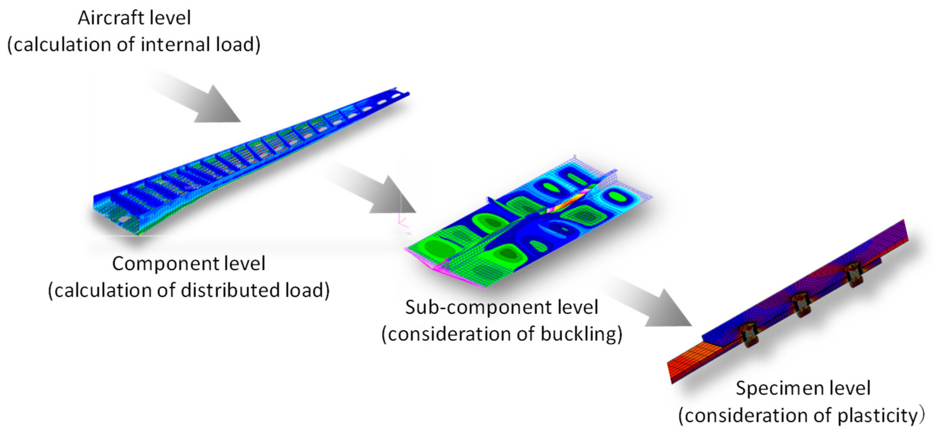
Figure 1. Practical finite element analyses for the design of an aircraft structure.
Aerospace 08 00196 g001
Figure 2. Definition of loads carried through rivet joints.
Aerospace 08 00196 g002
Figure 3. Experimental setup for tensile tests of a single-row joint.
Aerospace 08 00196 g003
Figure 4. Relationship between applied load and relative displacement where Fsq = 13 kN.
Aerospace 08 00196 g004
Figure 5. Detailed finite element model of a single-row joint.
Aerospace 08 00196 g005
Figure 6. Processes analyzed in the finite element analyses.
Aerospace 08 00196 g006
Figure 7. Distribution of displacement along the center line of the specimen where F0 = 15 kN.
Aerospace 08 00196 g007
Figure 8. Load–relative displacement curves of single-row joints with various squeezing forces.
Aerospace 08 00196 g008
Figure 9. Ratio of frictional force to total transferred load of the single-row joint.
Aerospace 08 00196 g009
Figure 10. Bearing load–relative displacement curve of the single-row joints.
Aerospace 08 00196 g010
Figure 11. Change in cross-sectional area of rivet shank after squeezing where Fsq = 19.5 kN.
Aerospace 08 00196 g011
Figure 12. Difference in cross-sectional area of rivet shank with respect to squeezing force.
Aerospace 08 00196 g012
Figure 13. Regularization of the curves of bearing load by the cross-sectional area of rivet shank.
Aerospace 08 00196 g013
Figure 14. Detailed model of triple-row joint for the finite element analyses.
Aerospace 08 00196 g014
Figure 15. Simplified model of triple-row joint for the finite element analyses.
Aerospace 08 00196 g015
Figure 16. Derivation of stiffness of nonlinear springs in the simplified model.
Aerospace 08 00196 g016
Figure 17. Load–relative displacement curves obtained from the detailed and simplified analysis of triple-row joints.
Aerospace 08 00196 g017
Figure 18. Ratio of distributed loads on each rivet to total applied load to the triple-row joints.
Aerospace 08 00196 g018
Table 1. Material properties used for the finite element analysis.
ParametersMS20426AD Rivet2024-T3 Alloy Bare Sheet
Young’s modulus71.7 GPa72.4 GPa
Poisson’s ratio0.330.33
Flow stressσtrue = C (εtrue)mσtrue = C (εtrue)m
Initial yield stress172 MPa310 MPa
Hardening parametersC = 544 MPa, m = 0.23
(εinitεtrue ≤ 0.02)
C = 676 MPa, m = 0.14
(εinitεtrue ≤ 0.02)
C = 551 MPa, m = 0.15
(0.02 < εtrue ≤ 1.0)
C = 745 MPa, m = 0.164
(0.02 < εtrue ≤ 0.1)
Slope of linear hardening curve 1034 MPa
(0.1 < εtrue ≤ 1.0)
Table 2. Hardware specification used for the finite element analyses.
ManufacturerHewlett Packard
Product nameProDesk 600 G2 SFF
Operating systemWindows 10 Professional
CPUCore i5-6500 Quad-core 3.20 GHz
MemoryPC4-17000 64 GBytes
Storage500 GBytes Hard disk
Publisher’s Note: MDPI stays neutral with regard to jurisdictional claims in published maps and institutional affiliations.