Abstract
The effect of manufacturing quality on rocket impact point dispersion is analyzed. The approach presented here applies to any type of rocket. Here, manufacturing quality is demonstrated for the unguided rocket, and by simulating four typical manufacturing errors: erroneously manufactured warhead, misalignment between the warhead and engine chamber, asymmetrically installed propellant, and error in nozzle manufacturing. A new methodology is proposed, which combines a 3D CAD model of the asymmetrical projectile (due to manufacturing errors) and the improved Six-degrees-of-freedom (6DOF) model of its flight into a comprehensive Monte-Carlo simulation. In that way, the rocket trajectory dispersion is correlated directly to the imperfection of the manufacturing process. Three quality levels are simulated (low, standard, and high quality), and each of the analyzed manufacturing errors depends on the chosen quality. The results show how important it is to impose the highest quality on nozzle manufacturing, and if this condition is not met, reveal if strict tolerances applied to other steps of the manufacturing process can compensate for the consequential drop of precision.
1. Introduction
Finding the right optimum between a criterion of precision and a criterion of production cost is of the utmost importance when designing a manufacturing process. The traditional approach to defining tolerances, based on empirical methods, does not give an adequate answer. For this reason, we propose a method that combines the 3D CAD (Computer-Aided Design) model of a realistic rocket (produced with some manufacturing errors) with the adjusted Six-degrees-of-freedom (6DOF) flight model. Two models are combined into one simulation that gives analytically justified manufacturing tolerances. The statistical analysis of the resulting rocket dispersion is a step further towards a deeper understanding of the imperfect projectile behavior, comparing to previous analyses [1,2]. The authors analyze a dispersion of rocket trajectories due to selected disturbances, among others due to the variations in inertia characteristics (and also launching pitch angle, propellant burning time, air density, etc.). In [1], a 122 mm rocket is analyzed, which was also chosen here as a case study. However, the cited papers introduce assumptions that narrow the applicability of their findings. In addition, limits of disturbances are set arbitrarily (for example, the longitudinal and lateral moments of inertia change by ±2%, rocket total mass and propellant mass change by ±1%, etc.).
Manufacturing errors were analyzed previously [3,4], leading to the conclusion that a certain level of uncertainty is inevitable when it comes to mechanical systems [5]. While [3] also analyzes the effect of dynamic asymmetry within arbitrarily chosen limits, a different approach is given in [4], where the serious consequences of dynamic imbalance are shown. However, a dynamic imbalance is not generated by the non-deterministic production imperfections, but intentionally by storing artillery shells on their side at hot conditions to induce mass asymmetry. The primary goal of both analyses is to determine the initial motion at and shortly after the barrel muzzle.
Insisting on particularly tight tolerances needlessly increases manufacturing costs [6] since all manufacturing errors indeed cause dispersion [7] but to various extent. Compared to the cited papers, the main novelty in the method presented here is the clear link between manufacturing errors and the resulting dispersion of rocket trajectories and impact points. Which error contributes the most to final dispersion can be shown only after the comprehensive simulation and analysis, as is the one proposed here. An extensive overview of simulation methods, and also the presentment of the CAD value for the manufacturing quality enhancement, is given in [8].
Critical stages of production, those in which errors lead to the greatest projectile imprecision, are crucial to be detected as early as possible. If detected before the actual manufacturing process begins, possibilities for changes are higher, and the cost of changes is lower compared to later phases of production [9].
Main conceptual differences between earlier works and the presented method should be emphasized. First, the proposed method goes back to the true origin of the inertia characteristics change, and the origin of impact points dispersion: it is the imperfect production that generates the inertia and geometrical characteristics change. Therefore, we set the starting point for our analysis there. Second, a large number of assumptions are omitted that are included in cited works (for example, the assumption that the projectile remains axis-symmetrical during the flight). This is explained later in Section 4. And finally, there is a new 6DOF flight model that is designed to facilitate tracking of an asymmetric projectile. Thanks to these novelties, the new 6DOF model remains suitable for fast computing, even when the above-mentioned simplifications and assumptions have been omitted, while they are required when working with the classical 6DOF model. The new 6DOF model, together with the new coordinate system and a new state vector, is also presented in Section 4. In this paper, four typical manufacturing errors are simulated for the case-study rocket. Changes in input data (i.e., the intensity of simulated manufacturing errors) result in variations of the rocket inertia characteristics, which are then introduced into the adjusted 6DOF model and ultimately lead to the dispersion of impact points. Analyzed misalignments are here solely due to manufacturing process imperfection, and not because of the rocket elasticity since it is assumed to be rigid [10].
2. Materials and Methods
A parametric 3D CAD model of an imperfect projectile is introduced. An example of the CAD model for such a projectile is presented in Figure 1. The 3D model is divided into two main components: the propellant that burns and therefore has changing inertia characteristics; and the platform that includes all other parts (fuse, warhead, engine chamber, nozzle, fins, etc.) with constant geometrical and inertia characteristics. Relevant inertia characteristics for the platform: mass mL, inertia tensor IL and center of gravity (CG) position are obtained from a CAD program and depend on the simulated manufacturing errors for the particular rocket.
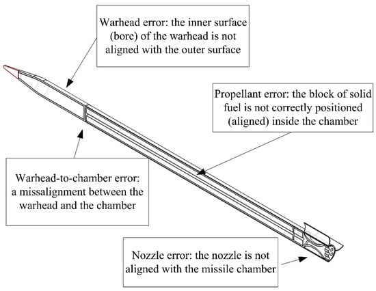
Figure 1.
Parametric 3D CAD model of the rocket; manufacturing errors marked.
2.1. Manufacturing Errors Simulation
For the imperfect rocket, geometrical and inertia characteristics differ from that of an ideal projectile. Four typical manufacturing errors are simulated: erroneously manufactured warhead, misalignment between the warhead and engine chamber (“warhead-to-chamber error”), asymmetrically installed propellant, and the thrust force misalignment caused by the error in nozzle manufacturing (Figure 1).
To facilitate tracking of the imperfect rocket flight, a new coordinate system called geometrical coordinate system (G-CS) is introduced. The G-CS is linked to the engine chamber axes of symmetry. The xG axis coincides with the longitudinal axis of symmetry, and transversal axes yG and zG are fixed to rocket fins. The origin is placed at the center of gravity. The attitude of the G-CS is determined relative to the vehicle-carried coordinate system (O-CS, i.e., north-east-down c.s.) by Euler angles: ϕG, θG, and ψG [11]. The transformation matrix from O-CS to G-CS is LGO = Lx (ϕG) Ly (θG) Lz (ψG). Manufacturing errors are expressed in regard to G-CS.
2.2. Warhead-to-Engine Chamber Misalignment
The warhead-to-engine chamber misalignment is described by two angles, as presented in Figure 2. The angle δHC lies in the plane of disturbance xG − xH, while the angle φHC defines the rotation of that plane relative to the reference plane xG − yG. Both angles δHC and φHC occur as stochastic parameters in the rocket 3D CAD model.

Figure 2.
Angles δHC and φHC, which describe the warhead misalignment.
Angles are defined as follows:
- δHC—the angle of misalignment in the plane of disturbance, dispersed according to the normal distribution (parameters of dispersion defined by the manufacturing quality level);
- φHC—the radial angle, defining the radial position of angle δHC, dispersed according to the uniform distribution.
Centers of gravity of the platform, propellant and the entire rocket are marked as CL, CP, and CR.
2.3. Warhead and Propellant Errors
The warhead error refers to the misalignment of the inner and outer warhead surface’s axes of symmetry. Consequently, the explosive is not aligned with the warhead outer geometry (Figure 3a) [12]. The propellant installment error causes the propellant and chamber axes of symmetry not to coincide (Figure 3b).
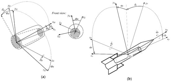
Figure 3.
(a) The warhead error [12]; (b) the propellant error.
In analogy with the warhead-to-chamber error, these two errors are also defined by the corresponding pair of angles: δH and φH for the warhead error, and by δP and φP for the propellant error. Both δH and δP angles are dispersed according to the normal distribution, but not necessarily with the same standard deviations, as will be explained later in the case study analysis. The radial angles φH and φP are dispersed according to the uniform distribution, in a full circle 0–360°.
If there is a δHC angle, both the warhead and the explosive charge rotate around the warhead-chamber joint. Additionally, if there is a δH angle, the explosive charge rotates inside the warhead around the same point. As a result, there is a rotation of both parts relative to the rocket CG (CR in Figure 2) and their CGs are no longer on the xG axis. This was introduced into the 6DOF model via the modified inertia tensor (obtained from the 3D CAD model) and altered moment of aerodynamic force.
2.4. Thrust Force Misalignment
It is already known that, for unguided rockets, the thrust force misalignment results in high impact point dispersion and therefore must be kept within very strict boundaries [13]. Misalignment of the thrust force may occur due to the asymmetrical combustion, but also if the nozzle is not perfectly aligned with the xG axis of symmetry. Here the combustion is assumed to be perfect, so the thrust force misalignment occurs only due to the nozzle manufacturing error.
The nozzle is a rotationally symmetrical body. A new auxiliary coordinate system is introduced, called the nozzle coordinate system (N-CS); it is aligned with the nozzle longitudinal axis of symmetry xN. The plane xG − xN is called the nozzle disturbance plane. The origin of N-CS is located at the nozzle center with a radial position . In analogy with the warhead-to-chamber error, the nozzle error is defined over two angles: δN and φN, as in Figure 4. The vector of the thrust force coincides with the xN axis and is deflected from the xG by the angle δN.
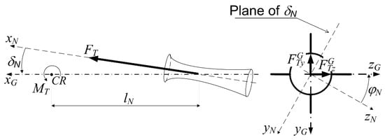
Figure 4.
Deflection of the thrust force relative to the rocket axis of symmetry xG.
Components of the thrust force in the G-CS are:
and its moment in the geometrical coordinate system is
where FT is the thrust force intensity, variable during the propellant combustion.
In the earlier industry-related experience, the nozzle error has been unsuccessfully corrected by imposing the highest level of manufacturing quality to other steps of production. Even if the danger of erroneous nozzle manufacturing is known, it is not known to what extent can its detrimental effect be compensated. As a method, the Monte Carlo simulation is chosen since it allows examining not only the impact of individual manufacturing errors but also their correlation that might otherwise be missed. Furthermore, it allows the analysis of the effect from a very wide spectrum of parameters (wind, mass, launching angle, etc.) that are not covered during the initial analysis, since it is focused on the production quality.
3. Monte-Carlo Simulation
The analysis of the effect that four manufacturing errors have on the impact points dispersion is performed by the Monte Carlo simulation. The value of Monte Carlo simulation for determining the manufacturing parameters is extensively described, for example in [14] where it is presented as a beneficial tool for analysis of tolerances used in mechanical assemblies. Its main advantage is flexibility and the ability to use various non-normal input or output distributions. In that way, it can describe a wider spectrum of problems and input variables compared to some other analytical methods, for example, the Failure Modes and Effects Analysis (FMEA) method, although this one also results in preventively identifying problems and gives their gradation based on severity, probability of occurrence, and probability of detection [15]. The scheme of simulation that is used for this case study (previously presented in [16]) is shown in Figure 5:
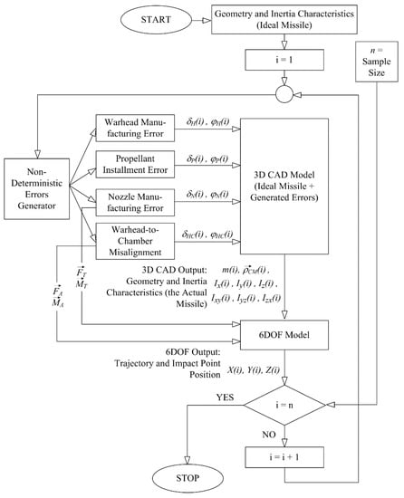
Figure 5.
Monte-Carlo Simulation scheme [16].
3.1. Statistical Process Control, Quality, and Process Capability Indices
The basic concept of statistical process control relates to the comparison of obtained data and calculated control within specification limits. Statistical process control is recognized as a modern method for the analysis of process capabilities. The process capability assessment measures efficiency and effectiveness of the process when there are no special causes of variation, in other words in the state of statistical control. When the process is under control, it will be less likely for parameters of the observed process to go beyond the control limits.
If there is a need to determine whether the process is within the control limits, three statistical instruments are suggested [17,18]: control charts, histograms, and mathematical analysis of distribution. Before assessing the capability of the process, it is necessary to choose a critical parameter or variable that will be controlled for. More about the control charts parameters, processes that are either in control or out of control, type of quality control policy (including the frequency and duration of sampling), and the cost of a quality program can be found in [19]. Due to the inability to obtain a larger sample of data from the actual manufacturing system, some key assumptions are introduced. Using literature sources [20] and available data from manufacturers, assumptions of the quality levels were made, and the quality of manufacturing is divided into three groups: low-quality, standard-quality, and a high-quality level, according to the amount of variability in the manufacturing process.
The calculation is made on the basis of the potential process capability index Cp, which estimates the ability of the process to produce the output (good parts) in the case when the mean is centered between the specification limits. The general assumption is that the manufacturing process is perfectly centered: to achieve more realistic conditions, the probability of the mean shift will be included in the simulation model. Table 1 shows the potential process capability and related manufacturing quality. DPMO is defect per million opportunities and Z-value is the value of how many standard deviations fit inside the specification limits. More about the quality analysis and the need to quantify the influential parameters for their later assessment can be found in [21].

Table 1.
Quality levels.
Since the index assumes the normal or near-normal data, the link between Cp and process variation σ can be made as follows: where USL is the upper specification limit, and LSL is the lower specification limit. The USL and LSL values are assumed according to the literature (for example [3]) and are unique for all types of manufacturing errors.
Using chosen USL, LSL, and the quality level, the estimation of the process deviation is calculated as:
More on the assessment of six-sigma quality indices can be found in [22].
3.2. Simulating Manufacturing Errors
Manufacturing errors are simulated in the rocket 3D CAD model. For each error, the appropriate pair of angles (nondeterministic variables) is introduced: δ which defines the angle of error or misalignment, and radial angles φ as explained in Section 2 and presented in Figure 3, Figure 4 and Figure 5.
Radial angles φ are dispersed according to the uniform probability distribution:
while δ angles are dispersed according to the normal probability density function:
The parameter σ for each error and each quality level is determined as in Equation (3), according to the appropriate USL and LSL. Values are given in Table 2.

Table 2.
Standard deviations for simulated errors, according to the chosen quality level.
As can be seen from Table 2, the upper and lower specification limits (USL and LSL) for warhead error are higher than USL and LSL for other error limits, as preliminary analysis has proven that the effect of this error is the weakest. As opposed to that, USL and LSL for the nozzle error are lower compared to the limits for other errors. The probability distribution function (PDF) is defined using the values listed in Table 2. For example, for the warhead-to-chamber error (and the low manufacturing quality) specification limits are set as follows: USL = 0.33°, LSL = −0.33°.
The standard deviation for δHC dispersion is then: , since Cp = 0.8335 is chosen as the average for the low-quality manufacturing level. Finally, if µ = 0 and σHC = 0.132, the PDF for δHC becomes:
The same procedure is done for the other two quality levels, resulting in the same form of PDFs but using the parameter σHC = 0.094 for the standard quality and σHC = 0.060 for the high quality level. PDFs for δHC are presented in Figure 6.
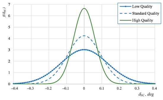
Figure 6.
PDFs for warhead-to-chamber manufacturing error δHC angles.
The same calculation is performed (but with different specification limits, as presented in Table 2) for δH, δP, and δN angles, giving the probability density function for each error and each of three quality level.
4. Flight Model Adapted for Imperfect Projectile
In classical flight mechanics [11], equations of motion are written in a frame coordinate system, the axes of which coincide with principal axes of inertia, or in its non-spinning variant, the ballistic coordinate system (B-CS). However, neither of these coordinate systems is suitable to describe the flight of the rocket with asymmetrical geometry or asymmetrical mass distribution. Therefore, the flight model is developed in the newly introduced geometric coordinate system (G-CS) and will be called G6DOF for distinction.
4.1. Governing Equations
Differential equations for G6DOF model are obtained from:
- Extension of Newton’s laws of motion for a body with variable mass. Includes the aerodynamic force , thrust force , gravity and Coriolis force . is a derivation of flight velocity, in G-CS:
- Derivation of angular momentum . Includes moment of aerodynamic forces and moment of thrust force , all written in G-CS:
- Matrix form of kinematic equation connecting attitude and angular velocity of the rocket :where R is given as
- Coordinates in the geocentric coordinate system (E-CS, Earth-fixed spherical coordinate system):with R being the radius of Earth and being its angular velocity.
The state vector for a rocket with mass asymmetry is defined according to Equations (7)–(11):
A difference between the classical 6DOF and the new G6DOF flight model is visible, because in , components of are introduced instead of . The aerodynamic velocity is also defined in the G-CS. Total angle of attack is , and angle between the airflow plane and vertical plane around xG is . Derivations of σ and ϕ are:
Wind is given only in horizontal plane, with no vertical wind: .
Angular velocity of the rocket is determined from the angular momentum: . The angular velocity of O-CS relative to the Earth is:
with the following transformation matrix from E-CS to O-CS: . Projectile’s angular velocity about axes of the airflow coordinate system (S-CS) can be determined as , with . Here ϕS is the attitude of the airflow around the longitudinal axis.
The presented model can be used for mid-range rockets flying at high altitudes. A change in gravity with altitude [13] could also be included into the system of equation.
4.2. Inertia Model
The inertia characteristics for propellant and platform can be obtained from the CAD model. A large number of assumptions that are common in the previously cited papers have been omitted, and the calculation is performed using the actual inertia characteristics. For example, the assumption is dismissed that the projectile inertia characteristics remain axis-symmetrical during the flight (in our method: ), which corresponds better to the real case. In addition, products of inertia are no longer assumed to be equal to zero (in our method: ). Even when the limits of production errors are chosen conservatively, a small change of inertia characteristics causes the rocket to deviate significantly from the target. It is no longer assumed that the main axes of inertia coincide with the outer geometry axes of symmetry, nor that the center of gravity (CR in Figure 2) remains on the xG-axis.
The analyzed rocket has the propellant shaped as a hollow cylinder, and the combustion occurring simultaneously over the external and internal surface. The propellant mass decreases linearly: , where is the initial propellant mass and is the total combustion time. Platform mass mL and its C.G. position are known.
Because of dynamic imbalance, centers of gravity for the platform and the complete rocket are not on the axis of symmetry (Figure 2). Moments of inertia for the propellant change proportionally with its mass: . Inertia tensor of propellant is given relative to its principal axes and center of gravity (denoted CP in Figure 2):
This inertia tensor must be recalculated relative to the entire rocket center of gravity CR, and relative to G-CS axes. Parallel axes theorem applies, and the transformation matrix LGP must be used:
In analogy, the platform’s inertia tensor also must be recalculated for the G-CS and translated to the projectile’s center of gravity (giving ). If platform axes of symmetry are not parallel to G-CS, then the appropriate transformation matrix should be used. Finally, tensor of inertia for the entire rocket is: .
4.3. Aerodynamics of an Asymmetrical Rocket
To complete the G6DOF model, components of aerodynamic force and aerodynamic moment are required. If harmonics can be neglected, then aerodynamic coefficients are independent of the roll angle ϕ (the angle between the airflow plane and the xG-zG plane):
with air density ρ, aerodynamic velocity V, and projectile reference area S. Components of aerodynamic moment for reference point RP in G-CS are:
If external surface of the rocket is rotationally symmetrical, the following relations among aerodynamic gradients exist: , . In Equation (14), are non-dimensional components of the rocket angular velocity. In the absence of data for the Magnus effect, and considering that these coefficients are not relevant for this analysis, the following is assumed: , and . For an ideal rocket, components of aerodynamic force along G-CS in Equation (18) are:
and for the reference point RP (defined with the position vector ), the aerodynamic moment in Equation (19) is given as
The aerodynamic moment in projectile’s center of gravity (defined with position vector ) is defined as .
The warhead-to-chamber misalignment creates the additional aerodynamic normal force NH in the plane of disturbance, and the moment MH, as shown in Figure 7.
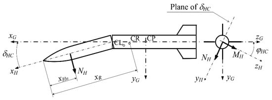
Figure 7.
Additional aerodynamic force and moment due to the warhead misalignment.
The intensity of additional normal force is . The distance from the rocket apex to the point of application of the force NH is xHn, and thus its moment in the projectile center of gravity is where xR is the distance from the apex of the rocket to its center of gravity. The aerodynamic gradient and the position of the force application xHn are determined according to [23]. Since both NH and MH are tied to the warhead geometry, they should be transformed into the G-CS:
Besides additional normal force NH, the warhead-to-chamber manufacturing error causes the additional induced drag. The aerodynamic derivative is Cxδ and it is dependent on the total angle of attack σ, as well as on the angle of misalignment δHC, as presented in Figure 8.
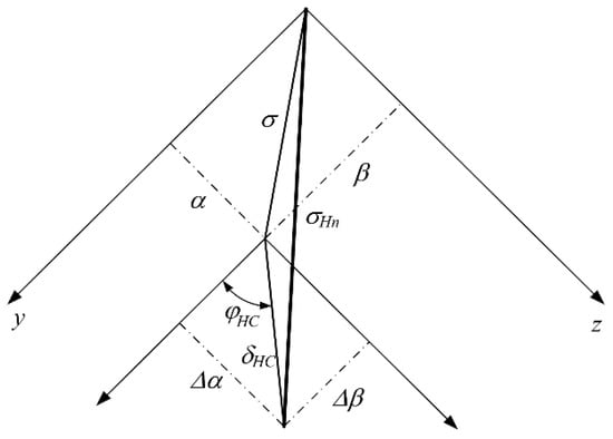
Figure 8.
Angle σHn as the summation of total angle of attack σ and the error angle δHC.
The solution is to replace the effect of these two angles with the resultant angle:
where ∆α and ∆β are components of δHC angle: , . The aerodynamic coefficient of the total drag, incorporating the influence of the misalignment angle δHC, would be usually defined as in Equation (18) but now with the application of σHn: .
5. Results and Discussion
To demonstrate the model, an unguided rocket similar to the 9M22U 122 mm projectile for the BM-21 GRAD multiple rocket launcher is analyzed as a case study (Figure 1). The rocket has the following characteristics:
- length: LM = 2.87 m;
- initial total mass: mM0 = 66.6 kg;
- initial mass of propellant: mP0 = 20.5 kg;
- mass of explosive and mass of the entire warhead: mE = 6.4 kg, mH = 18.4 kg;
- initial moments of inertia: Ix0 = 0.1499 kgm2, Iy0 = Iz0 = 41.58 kgm2.
Given data are valid for an ideal rocket, while the non-ideal rocket (i.e., being erroneously manufactured) will have altered inertia characteristics. For such a rocket, the assumption Iy0 = Iz0 is no longer valid.
The inertia and motor characteristics are taken from technical data sheets, while aerodynamic gradients are determined by the method described in [24] and confirmed in [1]. The coefficient Cx0(Ma) from Equation (20) is determined according to the etalon CD58(Ma) and adjusted so that the ideal rocket has the same maximum range as stated in the Firing Tables (in the NATO standard atmosphere). For the coefficient of induced drag, it is assumed Cxσ = Czα.
The target is at 13,700 m (which presents 2/3 of the maximum range). The rocket flight is simulated by the 6DOF model as defined by Equations (8)–(11), while geometric and inertia characteristics for each (non-ideal) rocket are obtained from the 3D CAD model. Figure 9 shows some parameters of the motion for an ideal projectile.
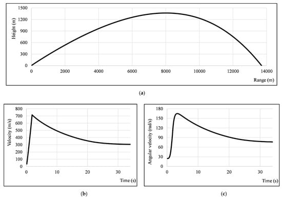
Figure 9.
For an ideal projectile: trajectory (a), flight velocity (b), and angular velocity (c).
The flight time is 34 s, and the trajectory apex is at 1367 m. The maximum velocity is 702 m/s, and the final velocity is 307 m/s. These data comply well with data gathered from the Firing Tables and the available technical documentation.
Because of simulated manufacturing errors, impact points are dispersed around the target. Simulations are used here as an approximation for expensive polygon tests, which is a common practice today due to financial limitations [25].
Trajectories have been simulated for 1000 rockets (for each quality level) manufactured with non-deterministic warhead-to-chamber errors, and non-deterministic nozzle misalignment errors. Parameters for errors dispersion are explained in previous sections, with 99.7% probability:
- error angles δH, δHC, δP and δN dispersed according to the normal distribution, with standard deviations depending on the production quality as given in Table 2;
- for all radial angles, dispersed according to the uniform distribution.
Figure 10 shows results of Monte Carlo simulations for three different quality levels.
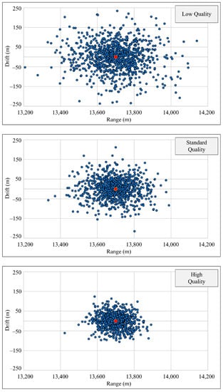
Figure 10.
Rocket impact points dispersion for various quality levels.
It is interesting to compare parameters of motion around the CoG for an ideal rocket, with a rocket produced with considerable errors (Case No. 1, a whole rocket made in low quality, production errors: δN = 0.151°, δH = 0.056°, δHC = 0.173°, δP = 0.091°). As presented in Figure 11, the angle of attack α and the angle of sideslip β for the non-ideal rocket (Figure 11b) are larger in comparison to the results for the ideal rocket (Figure 11a). The stability of the non-ideal rocket is not endangered, not even if produced with considerable production errors as the one analyzed here. In Figure 11c, the angle of attack for both projectiles is directly compared for the first five seconds, since later the angle of attack diminishes, and differences are difficult to be graphically presented.
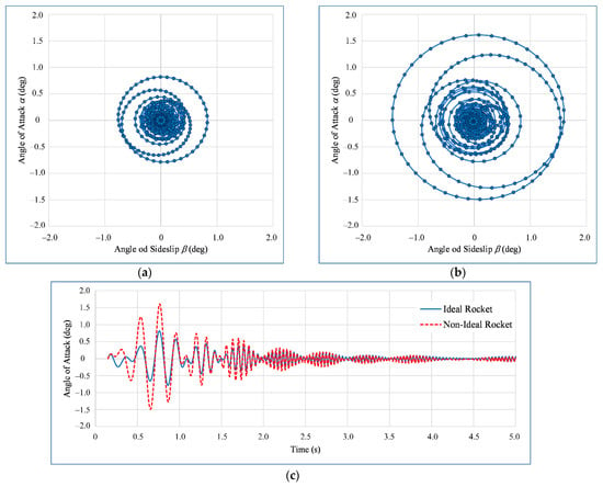
Figure 11.
Comparison of the pitching and yawing motion for ideally (a), and non-ideally manufactured projectile (b), and the comparison of angle of attack for both projectiles (c).
The drift and range results are independent of each other, which is proved by calculation of variance, covariance, and correlation coefficient consequently. The sample correlation coefficients are negligibly small, ranging from 0.01 to 0.06. Furthermore, using the test of significance, with a significance level of 5%, there is insufficient evidence to conclude that there is a correlation of the given data. As for normality of the response data (range and drift), the test was performed before the prediction interval calculation. The following is concluded:
- Descriptive location parameters (mean, mode and median) coincide.
- The absolute values of skewness and kurtosis for the analyzed variables are in the range of 0–0.1 and 0–0.5, respectively.
- In addition, the assumption of normality was tested using the normal—probability plots and Shapiro Wilk test.
Since the above-mentioned facts point out that the variables are normally distributed, the prediction interval is appropriate for describing the single-point estimation.
As Figure 10 and Table 3 show, there is a significant reduction of impact point dispersion area when higher quality levels are applied. The area of impact points dispersion corresponds well with the Firing Tables for GRAD rocket, used here as a corrective element since it obtains data from previously conducted extensive experiments and test firings. Results in Table 3 show 95% prediction intervals for impact points by the range and drift, and the impact point dispersion area for each of three simulated quality levels. Calculation of 95% prediction intervals, as well as areas of the impact point dispersion, shows that there is a significant reduction of 51% and 79% when standard or high quality level are applied, compared to that with the low quality of manufacturing.

Table 3.
Prediction intervals of the single impact point, various quality levels.
Knowing that the nozzle error, (i.e., the consequential thrust force misalignment) is causing a significant impact point dispersion, the analysis was expanded with three more cases, again using a Monte Carlo simulation with 1000 iterations for each case. Three new simulations examine the overall projectile dispersion when the nozzle error is manufactured at the low level, as in the already presented Case No. 1, but now with other rocket components manufactured at the standard level (Case No. 4), at the high level (Case No. 5) and even perfectly (Case No. 6). Table 4 gives dispersion characteristics for all six cases (No. 1–No. 6), given by range and drift.

Table 4.
The comparison of standard deviations for nine analyzed cases.
Finally, three more cases (numbered 7–9) are analyzed to inspect what happens if the nozzle error is removed as a contributing factor (δN = 0). An appropriate Monte Carlo simulation is prepared with 1000 iterations for each of three cases. Results show that in such a case, the dispersion area multifold decreases, regardless of whether other rocket parts are manufactured at a standard (Case No. 8) or even low quality (Case No. 7). If all parts are manufactured at high quality and δN = 0 (Case No. 9), a dispersion area matches the one of a guided rocket [26].
As expected, a dispersion of impact points decreases for better manufacturing quality. However, cases 4–6 indicate that the erroneously manufactured nozzle prevents a significant decrease of dispersion area, even if all other steps of production are raised to the highest quality level. Raising other steps of production from low to the standard quality level results in only 7% smaller dispersion area, and even raising it to the highest quality level gives a decrease of only 11%. In other words, if the nozzle is manufactured erroneously, all efforts and additional costs connected to the higher quality level are useless. This is valid even if a maximum nozzle error is only 2 mrad.
In Figure 12, two charts are presented, showing how critical nozzle manufacturing is. Both charts give the impact point dispersion if the entire rocket, except for the nozzle, is manufactured at the standard quality level. On the first chart, the nozzle is manufactured with low quality, and on the second, the nozzle error = 0. A difference between the two charts is a direct effect of nozzle imperfection, and it clearly causes the largest portion of the overall rocket dispersion.
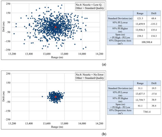
Figure 12.
Impact points dispersion with (a) and without nozzle error (b).
A preliminary DOE was conducted to determine the effects of different errors (factors). The significance of the factors was obtained using the ANOVA method, and standardized effects (presented via coefficient estimation) were calculated as presented in Table 5 and Table 6:

Table 5.
Effects for the nine analyzed cases, response variable: range.

Table 6.
Effects for the nine analyzed cases, response variable: drift.
The results confirm the conclusion that nozzle error has the highest effect on range and drift.
6. Conclusions
A method for estimating the effect of manufacturing errors on rocket precision is presented. The severity of manufacturing errors is examined by a Monte Carlo simulation, with 1000 iterations for each of the nine cases analyzed. These cases mutually differ according to the quality level imposed on particular parts of the rocket.
The Monte Carlo simulation consists of the non-deterministic manufacturing errors generator, a 3D CAD model of the rocket which provides changes of the inertia characteristics, and an adjusted 6DOF model of rockets flight which gives the position of impact points, dispersed due to simulated manufacturing errors. A new coordinate system (geometric CS) is introduced, helping to develop an improved 6DOF flight model (G6DOF) that facilitates tracking of imperfect or asymmetric rocket flight.
Monte Carlo simulations (denoted as Case No.1–9) analyze different combinations of four simulated manufacturing errors and three manufacturing quality levels. Extensive analysis singled out the nozzle error as particularly critical, which is in line with the conclusions of previous papers. However, it is shown not only that this error is the dominant cause of dispersion, but also that its impact is so strong, that even raising the manufacturing quality of all other parts of the rocket to the highest quality level does not compensate for the detrimental effect of the nozzle error.
That means that it is possible to achieve a reduction in the rocket cost by using a standard or even low quality level for less critical stages of production. As for the nozzle manufacturing, the strictest tolerances must be imposed, because by increasing the potential process capability index Cp, the projectile dispersion area decreases by up to 79%.
Analytically selected manufacturing tolerances can therefore achieve a major improvement in rocket accuracy, with a minimal increase in production costs. Alternative solutions regularly fail to comply with at least one of the desired criteria: either they result in a too expensive projectile or give impact points dispersion that is too large. Future research of the price of quality could further improve the algorithm for setting analytically validated manufacturing tolerances.
Author Contributions
Conceptualization, Z.T.; methodology, Z.T., M.V. and H.C.; software, Z.T.; validation, Z.T., M.V. and H.C.; formal analysis, Z.T., M.V. and H.C.; investigation, Z.T.; resources, Z.T.; data curation, Z.T.; writing—original draft preparation, Z.T.; writing—review and editing, Z.T., M.V. and H.C.; visualization, Z.T.; supervision, M.V.; project administration, Z.T.; funding acquisition, Z.T., M.V. and H.C. All authors have read and agreed to the published version of the manuscript.
Funding
This research received no external funding.
Data Availability Statement
Data kept by authors, available at the request.
Acknowledgments
Authors would like to acknowledge prof. Slobodan Janković, University of Zagreb (retired), for the invaluable help during the writing of this article.
Conflicts of Interest
The authors declare no conflict of interest.
References
- Khalil, M.; Abdalla, H.; Kamal, O.M. Trajectory Prediction for a Typical Fin Stabilized Artillery Rocket. In Proceedings of the 13th International Conference on Aerospace Sciences and Aviation Technology, ASAT-13; Military Technical College Cairo: Cairo, Egypt, 2009; Volume 13, pp. 1–14. [Google Scholar]
- Mihailescu, C.; Radulescu, M.; Coman, F. The analysis of dispersion for trajectories of fire-extinguishing rocket. In Recent Advances in Fluid Mechanics and Heat & Mass Transfer. In Proceedings of the 9th IASME/WSEAS International Conference on Fluid Mechanics & Aerodynamics (FMA′ 11), Florence, Italy, 23–25 August 2011; pp. 135–140. [Google Scholar]
- Liu, F.; Song, Y.; Yu, H.; Lin, W.; Zhang, J.; Si, Z.; Ding, M.; Rui, X. Study on the influence of projectile on muzzle disturbance. Def. Technol. 2018, 14, 570–577. [Google Scholar] [CrossRef]
- Decker, R.; Donini, J.; Gardner, W.; John, J.; Koenig, W. Mass asymmetry and tricyclic wobble motion assessment using automated launch video analysis. Def. Technol. 2016, 12, 113–116. [Google Scholar] [CrossRef]
- Dourado, A.; Cavalini, A.; Steffen, V. Uncertainty quantification techniques applied to rotating systems: A comparative study. JVC/J. Vib. Control 2018, 24, 3010–3025. [Google Scholar] [CrossRef]
- Ullman, D. The Mechanical Design Process, 6th ed.; David Ullman LLC: Independece, OR, USA, 2017; ISBN 9780999357804. [Google Scholar]
- Grignon, C.; Cayzac, R.; Heddadj, S. Improvement of Artillery Projectile Accuracy. In Proceedings of the 23rd International Symposium on Ballistics; Gálvez, F., Sánchez-Gálvez, V., Eds.; International Ballistics Committee, Universidad Politécnica: Tarragona, Spain, 2007; pp. 747–754. [Google Scholar]
- Mourtzis, D. Simulation in the design and operation of manufacturing systems: State of the art and new trends. Int. J. Prod. Res. 2020. [Google Scholar] [CrossRef]
- Fabrycky, W.; Blanchard, B. Life Cycle Cost and Economic Analysis, 1st ed.; Prentice Hall: Hoboken, NJ, USA, 1991; ISBN 978-0135383230. [Google Scholar]
- Xu, T.; Rong, J.; Xiang, D.; Pan, C.; Yin, X. Dynamic Modeling And Stability Analysis Of A Flexible Spinning Missile Under Thrust. Int. J. Mech. Sci. 2016, 119, 144–154. [Google Scholar] [CrossRef]
- Etkin, B. Dynamics of Atmospheric Flight; Dover Publications: Mineola, NY, USA, 2005; ISBN 978-0486445229. [Google Scholar]
- Trzun, Z.; Vrdoljak, M.; Cajner, H. Statistical Analysis of Missile’s Trajectory Deviation Due to Production Errors. In Proceedings of the 91st Annual Meeting of the International Association of Applied Mathematics and Mechanics (GAMM); Wiley-VCH GmbH: Kassel, Germany, 2021. [Google Scholar]
- Gantmakher, F.; Levin, L.; Dryden, H. The Flight of Uncontrolled Rockets; Pergamon Press: Oxford, UK, 1964. [Google Scholar]
- Kosec, P.; Škec, S.; Miler, D. A comparison of the tolerance analysis methods in the open-loop assembly. Adv. Prod. Eng. Manag. 2020. [Google Scholar] [CrossRef]
- Vulanović, S.; Delić, M.; Kamberović, B.; Beker, I.; Lalić, B. Integrated management systems based on risk assessment: Methodology development and case studies. Adv. Prod. Eng. Manag. 2020. [Google Scholar] [CrossRef]
- Trzun, Z.; Vrdoljak, M. Monte Carlo Simulation of Missile Trajectories Dispersion due to Imperfectly Manufactured Warhead. In Proceedings of the 31st DAAAM International Symposium; Katalinic, B., Ed.; DAAAM International: Mostar, Bosnia and Herzegovina, 2020; pp. 574–583. [Google Scholar]
- Breyfogle, F. Implementing Six Sigma: Smarter Solutions Using Statistical Methods, 2nd ed.; John Wiley & Sons: New York, NY, USA, 2003; ISBN 978-0471265726. [Google Scholar]
- Quinino, R.C.; Cruz, F.R.B.; Ho, L.L. Attribute inspection control charts for the joint monitoring of mean and variance. Comput. Ind. Eng. 2020, 139. [Google Scholar] [CrossRef]
- Farahani, A.; Tohidi, H. Integrated optimization of quality and maintenance: A literature review. Comput. Ind. Eng. 2020. [Google Scholar] [CrossRef]
- Jankovic, S.; Gallant, J.; Celens, E. Dispersion of an artillery projectile due to its unbalance. In Proceedings of the 18th International Symposium on Ballistics, San Antonio, TX, USA, 15–19 November 1999; Reinecke, W.G., Ed.; The University of Texas at Austin Southwest Research Institute: San Antonio, TX, USA, 1999; pp. 128–141. [Google Scholar]
- Katsiropoulos, C.V.; Pantelakis, S.G. A Novel Holistic Index for the Optimization of Composite Components and Manufacturing Processes with Regard to Quality, Life Cycle Costs and Environmental Performance. Aerospace 2020, 7, 157. [Google Scholar] [CrossRef]
- Chen, K.S.; Chen, H.T.; Chang, T.C. The construction and application of Six Sigma quality indices. Int. J. Prod. Res. 2017, 55, 2365–2384. [Google Scholar] [CrossRef]
- Mingireanu, F.; Georgescu, L.; Murariu, G.; Mocanu, I. Trajectory modeling of grad rocket with low-cost terminal guidance upgrade coupled to range increase through step-like thrust-curves. Rom. J. Phys. 2014, 59, 369–381. [Google Scholar] [CrossRef]
- Jankovic, S. CAD of the Unguided Missiles. In Proceedings of 11th International Symposium on Ballistics; Celens, E., Ed.; Royal Military Academy Brussels: Brussels, Belgium, 1989; pp. 749–759. [Google Scholar]
- Gao, Y.; Liu, H.; Zhou, Y. An Evaluation Method of Combat Aircraft Contribution Effectiveness Based on Mission Success Space Design. Int. J. Aeronaut. Space Sci. 2019. [Google Scholar] [CrossRef]
- Głębocki, R.; Jacewicz, M. Parametric Study of Guidance of a 160-mm Projectile Steered with Lateral Thrusters. Aerospace 2020, 7, 61. [Google Scholar] [CrossRef]
Publisher’s Note: MDPI stays neutral with regard to jurisdictional claims in published maps and institutional affiliations. |
© 2021 by the authors. Licensee MDPI, Basel, Switzerland. This article is an open access article distributed under the terms and conditions of the Creative Commons Attribution (CC BY) license (https://creativecommons.org/licenses/by/4.0/).