Article

Design of the Electronic Engine Control Unit Performance Test System of Aircraft

1
Department of Defense Science & Technology-Aeronautics, Howon University, 64 Howondae 3gil, Impi, Gunsan 54058, Korea
2
School of Mechanical Convergence System Engineering, Kunsan National University, 558 Daehak-ro, Miryong-dong, Gunsan 54150, Korea
*
Author to whom correspondence should be addressed.
Aerospace 2021, 8(6), 158; https://doi.org/10.3390/aerospace8060158
Submission received: 22 March 2021 / Revised: 18 May 2021 / Accepted: 21 May 2021 / Published: 3 June 2021

Abstract

:
In this study, a real-time engine model and a test bench were developed to verify the performance of the EECU (electronic engine control unit) of a turbofan engine. The target engine is a DGEN 380 developed by the Price Induction company. The functional verification of the test bench was carried out using the developed test bench. An interface and interworking test between the test bench and the developed EECU was carried out. After establishing the verification test environments, the startup phase control logic of the developed EECU was verified using the real-time engine model which modeled the startup phase test data with SIMULINK. Finally, it was confirmed that the developed EECU can be used as a real-time engine model for the starting section of performance verification.

1. Introduction

The EECU is a very important component in aircraft engines, and the verification test for numerous items should be carried out in its development process. Since it takes a lot of time and cost to carry out such verification test using an actual engine, and an expensive engine may be damaged or a safety hazard may occur, the simulator which virtually generates the same signals with the actual engine is essential [1]. The virtual engine simulator which replaces the actual engine should be able to provide the simulation of engine operation in real time at almost the same level as the actual engine operation. Therefore, the simulation speed should be as fast as the speed of the actual system to carry out input, calculation and output within the time range specified by the user. The development of a real-time engine model which can carry out calculation at almost real time and appropriate hardware is necessary for real-time simulation.
Many studies of electronic engine control systems of gas turbine engines have been conducted. Among the previous studies, W.J. Davies et al. performed F-14 aircraft and propulsion control integration evaluation. Their paper presented the FADEC/F-14 integration evaluation performed by PWA and discussed the benefits of the FADEC/F-14 integrated system [2]. H. Yamane et al. carried out an investigation on aspects of aircraft engine control systems. In their work, various electronic control systems for aircraft engines were proposed [3]. F. Schwamm conducted research on FADEC computer systems for safety-critical applications. In Schwamm’s work, the trends in FADEC development were investigated [4]. K. Hjelmgren et al. performed a study on the reliability analysis of single-engine aircraft FADEC. Their paper presented a reliability analysis of two options to fault-tolerant FADEC intended for control of an aircraft gas turbine engine [5]. K. Ito et al. performed a study on the optimal self-diagnosis policy for FADEC of gas turbine engines. In their paper, FADEC is self-diagnosed at the nth control calculations. Numerical examples were finally provided [6]. Ding Shuiting et al. conducted a study on the FHA (functional hazard assessment) method for the VBV (variable bleed valve) position control function of a FADEC system based on an aero engine dynamic model [7]. G.I. Pogorelov et al. carried out research on application of neural network technology and high-performance computing for identification and real-time hardware-in-the-loop simulation of gas turbine engines [8]. Keeyoung Choi et al. performed a study on the development of an integrated high-fidelity helicopter and engine simulation for control system design [9]. Kang-Yi Lee et al. carried out a study on the certification of electronic engine controls [10]. Joo-Hyun Jung et al. conducted a study on the T-50 engine airstart test. Their paper presented the results of airstart tests performed to verify the T-50 airstart capability for various flight conditions [11]. F. Lu et al. performed research on rotating detonation wave propulsion about experimental challenges, modeling, and engine concepts [12]. S. Jafari et al. conducted a study on meta-heuristic global optimization algorithms for aircraft engine modeling and controller design [13]. S. Jafari et al. conducted a study on modeling and control of the starter motor and startup phase for gas turbines [14]. M. Montazeri-Gh et al. performed research on bond graph modeling of a jet engine with an electric starter [15]. A. Imani et al. studied the research on multi-loop switching controllers for aircraft gas turbine engines with stability proof [16]. Salehi. A. et al. conducted a study on hardware-in-the-loop simulation of a fuel control actuator of a turboshaft gas turbine engine [17]. M. Montazeri-Gh et al. analyzed different numerical linearization methods for the dynamic model of a turbofan engine [18]. M. Song et al. conducted research on optimization for the starting process of a turbofan engine under a high-altitude environment [19]. J. Bai et al. carried out a study on a nonlinear single controller of the DGEN380 aero engine design [20]. Y. Qian et al. conducted a study on LPV/PI control for a nonlinear aero engine system based on guardian maps theory [21]. I. Yazar et al. carried out research on a simulation-based dynamic model and speed controller design of a small-scale turbojet engine [22]. K. Beneda developed modular FADEC for a small-scale turbojet engine [23]. J. Lutambo conducted a study on aircraft turbine engine control system development [24]. Bai Jie carried out research on controller design for a small aero engine [25]. S. Victor et al. performed a study on robust control system design of a turbofan [26]. J. W. Connolly et al. conducted research on propulsion control modeling for a small turbofan engine [27]. Joseph. W. et al. carried out a study on advanced control considerations for turbofan engine design [28]. J. Csank et al. performed a study on a model-based engine control architecture with an extended Kalman filter [29]. R. Andoga conducted a study on intelligent situational control of small turbojet engines [30].
After many years of study, various theories of electronic engine control systems for gas turbine engines have been proposed. Even though various engine control design theories have been proposed, little research work on the development of experimental equipment for electronic engine control systems has been conducted.
In this study, our research group developed a real-time engine model which was essential for the development of the EECU, a core device in the aircraft engine, and the test bench which embedded the real-time engine model on the real-time simulator and generated the same physical signal with the sensor signal from the actual engine. The test bench’s function test and the test bench’s interface and interworking test were performed. Additionally, then, the real-time startup phase engine model verification test, real-time normal operation phase engine model verification test and target EECU performance verification test were carried out using the developed test bench. Finally, the test results were analyzed.

2. Engine Model

2.1. Target Engine

The target engine for the EECU to be developed is a small turbofan engine which is a two-spool and non-mixing type. The general specifications of the target engine are as shown in Table 1. The target engine is a DGEN 380 turbofan engine. Figure 1 shows the configuration of the target engine. Figure 2 shows the configuration and station numbers employed for a two-spool turbofan engine.

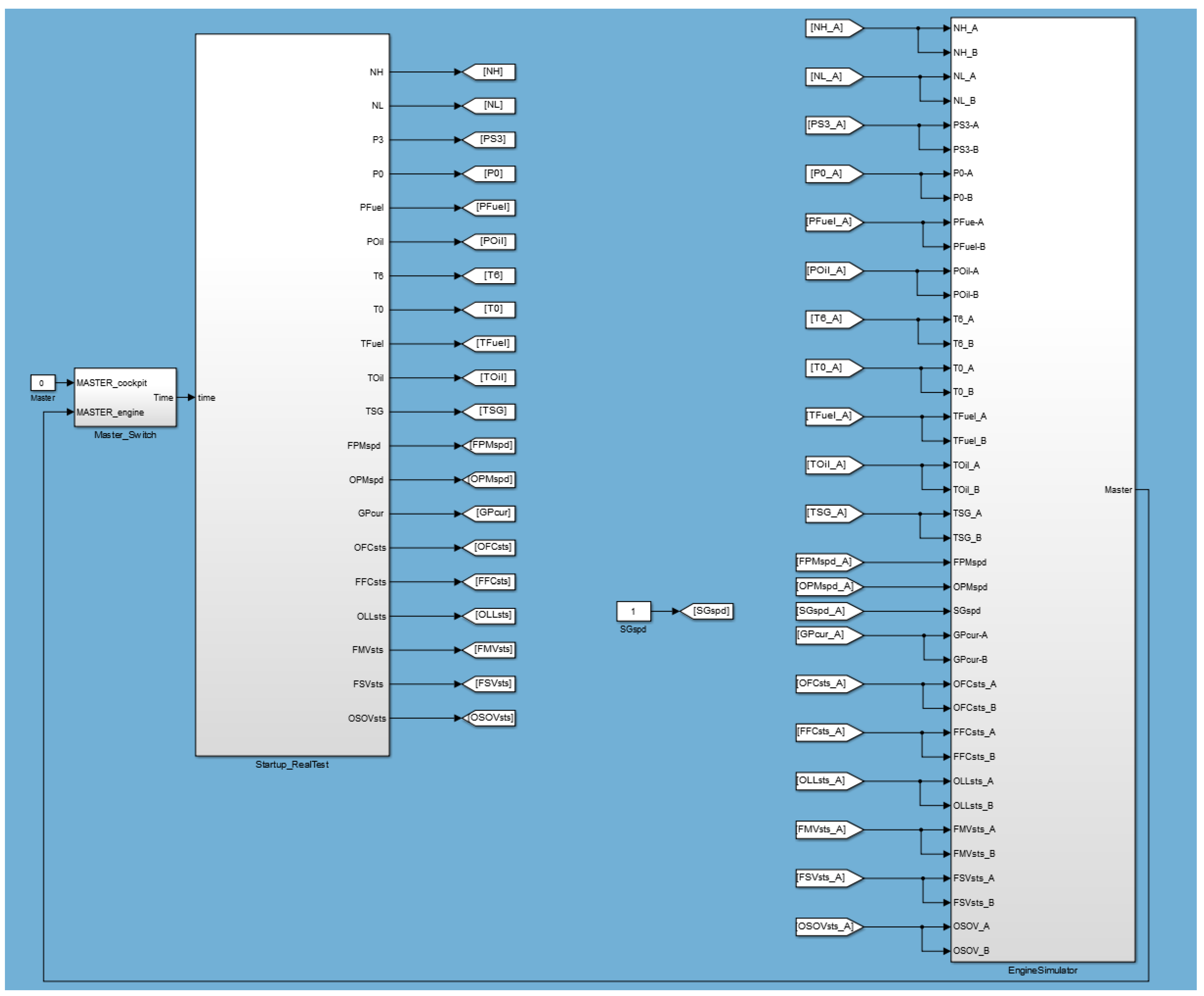
2.2. Real-Time Startup Phase Engine Modeling

In this study, a real-time heat flow transient performance model was developed. The heat flow model is the most accurate model of the real-time engine models. This method does not require iteration. Therefore, it is a real-time engine model most commonly used for engine control system hardware development. In this work, a model was developed by applying the following equation [31]:
d ρ 4 d t = ( W 3 W 4 + W F ) v
where d ρ 4 d t is the change rate of the density at the combustor outlet, and v is volume of the combustor.
d T 4 d t = C P 3 × T 3 × W 3 C P 4 × T 4 × W 4 + W F × L H V ) C V × T 4 × v × d ρ d t
where LHV is the fuel calorific value. Equation (2) is the change rate of the temperature at the combustor outlet.
P 4 = ( 1 + γ 1 2 × M 2 ) 1 γ 1 × R × T × ( W i n W o u t ) v
D P c o l d = K c o l d × P 31 × ( W 31 × T 31 P 31 ) 2
where   D P c o l d is the cold loss of the combustor, K c o l d is the cold loss value and M is the Mach number of the turbine inlet.
D P h o t = K h o t × P 31 × ( T 4 T 31 1 ) × ( W 31 × T 31 P 31 ) 2
where   D P h o t is the heat loss of the combustor, and K h o t is the heat loss value.
W = Q × P T
T 4 T 5 = T 4 × η 4 × ( 1 1 P R 4.5 γ 1 γ )  
P 1 P 0 P 0 = 100 × ( 1 R R F ) × P 0 P a m b P 0
where RRF is the ram recovery coefficient.
T 3 T 2 = T 2 × P R 2.3 γ 1 γ 1 η 2
d P d t = ( 1 + γ 1 2 × M 2 ) 1 γ 1 × R × T × W i n W o u t v
where d P d t is the pressure change rate of the volume. A real-time transfer function transient performance model was considered by the following equation:
N L ( t ) = W F ( t ) × ( 1 T C l e a d T C l a g ) + ( 1 T C l e a d T C l a g ) × [ N L ( t 1 ) + ( N L ( t ) W F ( t 1 ) × ( 1 e d t T C l a g ) ]  
where N L ( t ) is the number of revolutions of the low-pressure turbine at time t. A real-time lumped parameter transient performance model was considered by the following equation. The partial derivative of the state variable is obtained from all other parameters.
N L t = N L d o t N L × ( N L N L b ) + N L d o t N H × ( N H N H b ) + N L d o t W F × ( W F W F b )
where b is the operating point.
The modeling of the real-time startup phase engine model in the form of a lookup table based on time was carried out through the reconfiguration of startup phase test data measured from the target engine EECU, as shown in Figure 3. The real-time startup phase engine model was composed of a “Master Switch” module which played the role to start the engine, a “Startup Real Test” module which provided startup phase data for 0~109 s in the lookup table and an “Engine Simulator” module which generated a physical signal by converting all output signals into analog and discrete signals. Additionally, a “switch model” was added to simulate the short circuit test by assigning a switch to all signals separately and turning on or off a certain signal during the simulation. SIMULINK was used, as shown in Figure 3. In order to load the modeled real-time startup phase engine model on the engine simulator, SIMULINK was used.

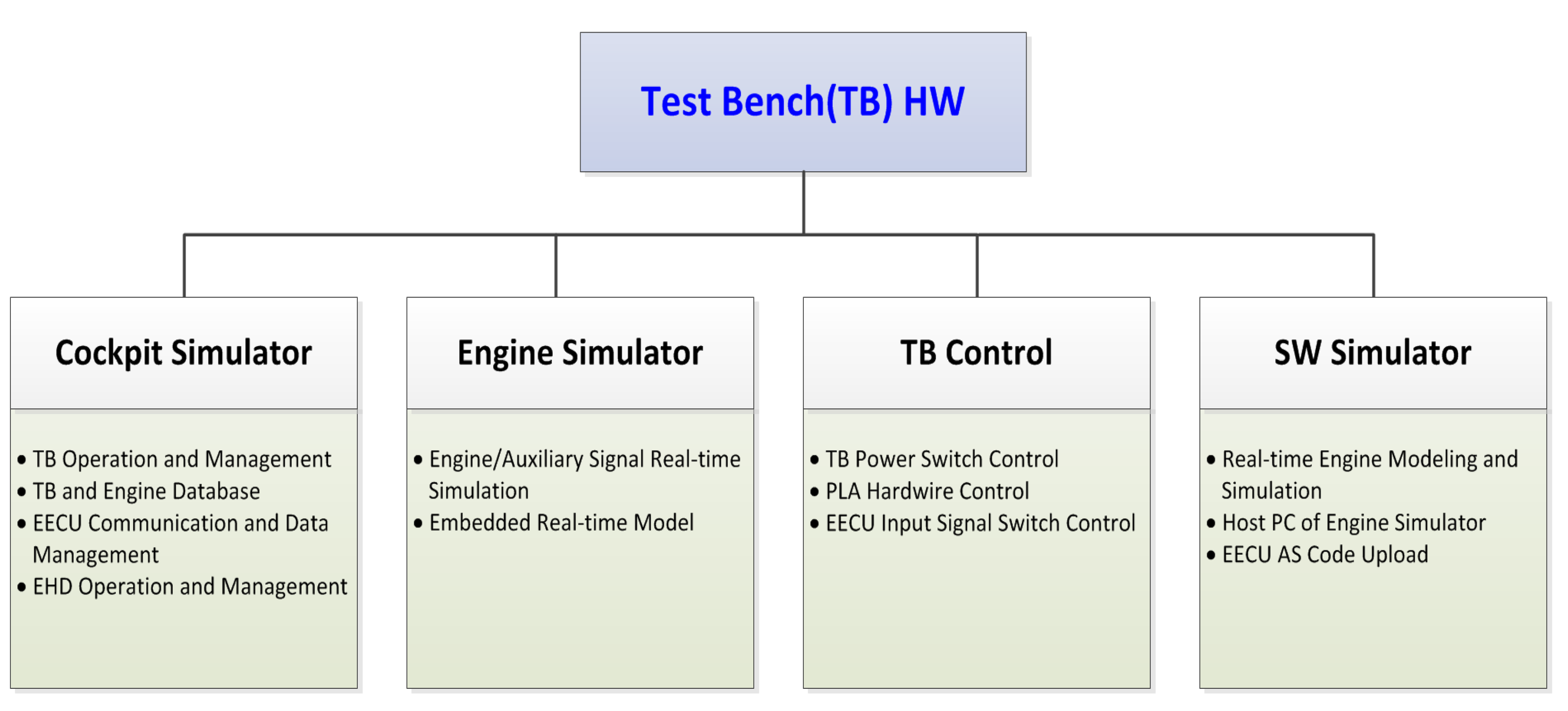
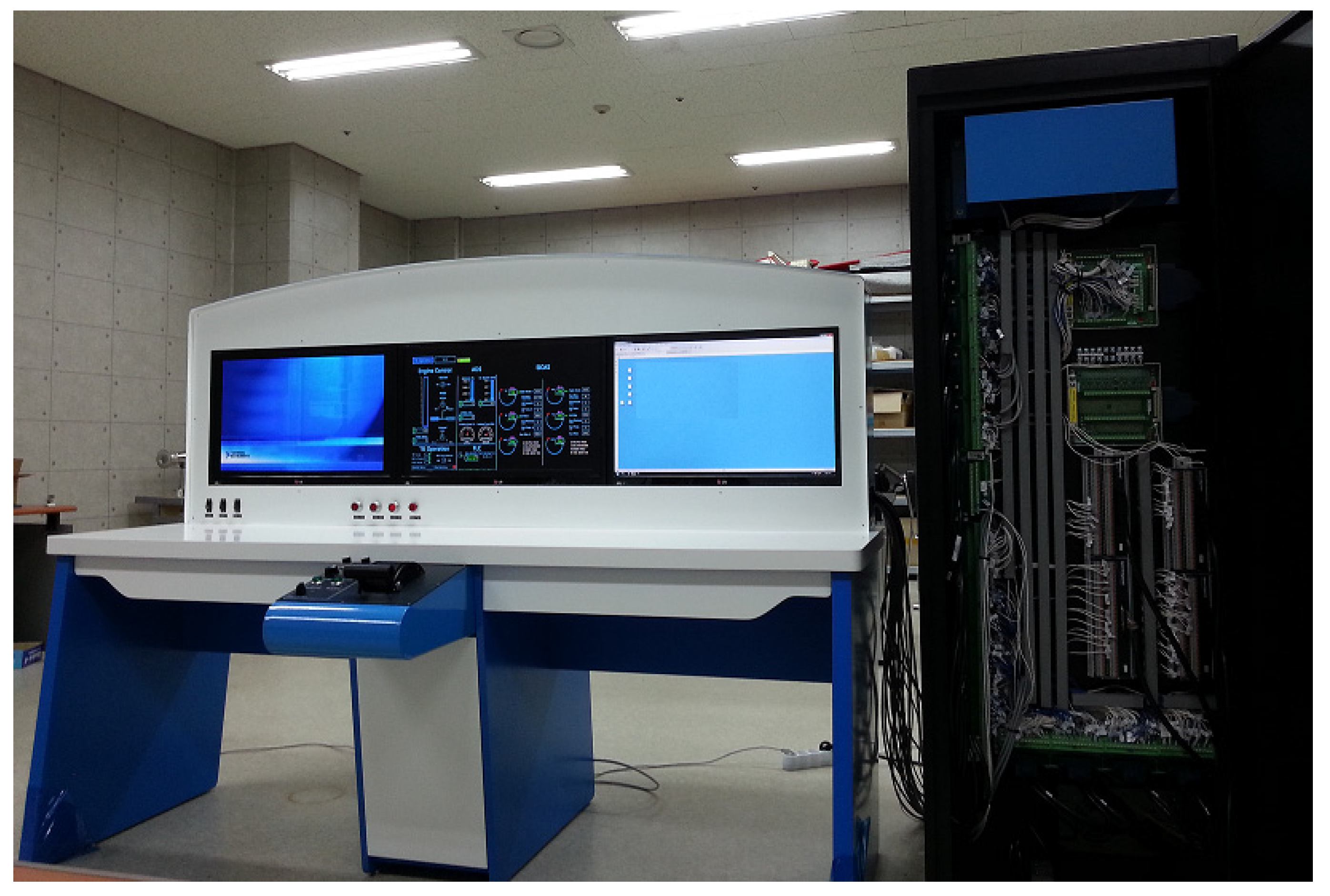
3. Test Bench Development

In this study, the test bench (TB) was configured for the purpose of verifying the target EECU by loading the real-time engine model. The test bench was configured to satisfy the requirements to enable the integrated performance test of the target EECU. The test bench provided the interface for installing and operating the target EECU as well as the virtual engine which could simulate fault signal input and the same input and output signals as the actual engine through the dual channel.
The test bench consists of a hardware unit (HW) including a real-time engine simulator, a flight vehicle/cockpit simulator, a software simulator, a mapping box, cables and connectors, a power supply unit, a console and desk and a monitor and operating software unit (SW).
The hardware unit in the test bench consists of a “cockpit simulator” which handles the operation and management of the test bench, management of the test database of the test bench and target engine, management of the ARINC429 communication and data and operation and management of the EHD module, a “real-time engine simulator” which is embedded with the real-time engine model simulating the same performance as the actual engine and simulates engine and drive system signals in real time, “engine controls” which play the role of the cockpit where hardwire signals are sent to the EECU directly and various switches are operated to control the EECU through mechanical production of a PLA lever which adjusts the engine thrust and a “software simulator” which carries out the modeling of the real-time engine embedded in the engine simulator or plays the role of the host PC for the engine simulator and uploads software on the target EECU. HW block diagrams of the test bench are shown in Figure 4.
The test bench operation software was programmed using NI LabVIEW, and it consists of a “TB Operation” program of the main GUI which operates and controls the whole test bench, an “EECU Monitoring” program which monitors and uses the target EECU and all input and output signals through the ARINC429 communication, an “EECU Test” program which can monitor and save data in the verification tests such as the target EECU performance test, logic test and startup phase test and an “EHD” program which creates a database of data saved after the target engine test offline and carries out state diagnosis, trend monitoring and maintenance phase management. SW block diagrams of the test bench are shown in Figure 5, and the detailed specifications of the developed TB are shown in Table 2. The conceptual diagram of the developed TB is shown in Figure 6 and Figure 7.

4. EECU Verification Test

4.1. Functional Test of Test Bench

The manufactured test bench is shown in Figure 7. The state of the test bench was inspected through the functional test after integrating the test bench. For the functional test of the test bench, the inspection cable was connected to each pin at the end of the cable directly connected to the target EECU. The test items, standards and methods for the signals in all items of channels A and B were summarized as shown in Table 3. Three measurements were carried out for each test item, and if all measurement values were within the error range, an “OK” judgment was given.
The result of the functional test is as shown in Table 4, and the measurement values for all test items in channels A and B are within the error range; therefore, it can be regarded that the functional reliability of the test bench for the verification test of the target EECU has been secured.

4.2. EECU Interface and Interworking Test

The interface and interworking test between the test bench and target EECU is the test to check if the data transmission and reception between the test bench and target EECU through the ARINC429 communication are carried out smoothly after connecting the test bench and EECU with a cable and operating the test bench operating program. The interface and interworking test was carried out in the process as shown in Figure 8.
At this time, a separate interface test engine model was embedded in the engine simulator, and the test items, standards and methods for the signals in all items of channels A and B were summarized as shown in Table 5 in a similar way to the functional test. Three measurements were carried out for each test item, and if all measurement values were within the error range, an “OK” judgment was given.
The result of the interface and interworking test between the test bench and target EECU is as shown in Table 6, where it is confirmed that all test items in channels A and B were within the error range. Therefore, it can be regarded that the functional reliability for data signals through the communication between the test bench and target EECU has been secured for the following verification test of the target EECU.

4.3. Real-Time Engine Model Verification Test

The interworking test with the target EECU was carried out by loading the startup phase real-time engine model established from data obtained through trial operation of the target engine on the engine simulator.
It was confirmed from the NH, NL, T6 and FMVsts result on the startup phase that the test data matched well within 1% in the whole startup phase, as shown in Figure 9, Figure 10 and Figure 11, and data were saved in a fixed time interval (0.02 s). Therefore, it was confirmed that analog sensor output signals and discrete output signals of the actual engine were monitored in the engine simulator embedded in the real-time engine model through the ARINC429 communication, and the signals were within the permissible error range of the target EECU. It was verified that this model could be used as the startup phase real-time engine model for the startup phase performance verification of the target EECU.

4.4. Startup Phase Control Logic Verification Test

EECU software consists of a control logic, application software and a real-time operating system. Here, the control logic handles the engine speed control, sequence control, engine state monitoring and engine protection functions. It is the most important part in the development of EECU software. The application software handles the system communication interface and dual channel management, and the real-time operating system manages the tasks of the application program to be carried out in a consistent and appointed time.
The verification test of the control logic which performed the most important role in the EECU software was carried out using the test bench developed through this study. Currently, the target EECU is being developed in the country. Therefore, the test was carried out for the control logic of the startup phase which was developed up to date. When the target EECU is developed completely in the future, the control logic test will be carried out for the whole operation phase of the target engine. The startup phase control logic test was carried out in the process as shown in Figure 12.
The EECU delivers FPMcmd, FMVcmd and FSVcmd output values according to the control logic calculation result to the engine in the startup phase, as shown in Figure 13, Figure 14 and Figure 15, and the engine receives the input of this command. The result shows that the control logic in the early stage of development shows a significant difference from the reference data. Therefore, the reasons for the error occurrence from the control log were analyzed, and the control logic was modified accordingly. The test was carried out again until the final control logic test result almost matched with the target data.

5. Conclusions

A test bench for the performance test of an EECU was developed, and the test was carried out. The test bench’s functional test, test bench’s interface and interworking test, real-time startup phase engine model verification test and target EECU performance verification test were carried out using the configured test bench, and the test results were analyzed.
As the result of the TB functional test, the measurement values for all test items in channels A and B were within the error range; therefore, the functional reliability of the test bench for the verification test of the target EECU was secured. As a result of the interface and interworking test between the test bench and target EECU, it was confirmed that all test items in channels A and B were within the error range. Therefore, the functional reliability for data signals through the communication between the test bench and target EECU was secured for the verification test of the target EECU.
As a result of the startup phase verification test after the verification of the test bench, it was confirmed that analog sensor output signals and discrete output signals of the actual engine were monitored and saved accurately in a 0.02 s interval in the engine simulator embedded in the real-time engine model through the ARINC communication, and the signals were within the permissible error range of the target EECU. Therefore, it was confirmed that this model could be used as the startup phase real-time engine model for the startup phase performance verification of the target EECU. Additionally, as a result of the control logic test, the control logic in the early stage of development showed a significant difference from the reference data. Therefore, the reasons for the error occurrence from the control log were analyzed, and the control logic was modified accordingly. The test was carried out again until the final control logic test result almost matched with the target data. Currently, the target EECU is being developed in the country. Therefore, the test was carried out for the control logic of the startup phase which was developed up to date. When the target EECU is developed completely in the future, the control logic test will be carried out for the whole operation phase of the target engine.

Author Contributions

S.K., conceptualization, software, validation, writing—original draft preparation; H.P., writing—review and editing, work guidance. Both authors have read and agreed to the published version of the manuscript.

Funding

This research was funded by the Korea Aerospace Technology Research Association (Project No. 10043602, Development of the EECU platform aircraft for gas turbine engine FADEC) as part of the aerospace parts & technology development project supported by the Ministry of Trade, Industry and Energy, which is graciously acknowledged. This research was funded by the Howon University research fund. This research was supported by the Basic Science Research Program through the National Research Foundation of Korea (NRF) funded by the Ministry of Education (No. 2018R1D1A1B07043553). This research was supported by the Korea Institute for Advancement of Technology (KIAT) grant funded by the Korean government (MOTIE) (P0012769, The Competency Development Program for Industry Specialist).

Data Availability Statement

The data presented in this study are available on reasonable request from the corresponding author.

Acknowledgments

The authors would like to thank Changduk Kong.

Conflicts of Interest

The authors declare no conflict of interest.

Abbreviations

EECUelectronic engine control unit
ρdensity
ttime
νvolume
LHVfuel calorific value
DPcoldcold loss of combustor
DPhotheat loss of combustor
Kcoldcold loss value
Khotheat loss value
RRFram recovery coefficient
RTDresistance temperature diode
PTCpositive temperature coefficient thermistor
EHDengine health diagnostic
GUIgraphical user interface
EECUelectronic engine control units
Ppressure
NL (t)the number of revolutions of low pressure at time t
Boperating point

References

  1. Lobo, L.M.; Dufour, C.; Mahseredjian, J. Real-time simulation of more-electric aircraft power sytems. In Proceedings of the EPE’13 ECCE Europe Conference, Lille, France, 3–5 September 2013; pp. 1–10. [Google Scholar]
  2. Davies, W.J.; Hoelzer, C.A.; Vizzini, R.W. F-14 aircraft and propulsion control integration evaluation. J. Eng. Power 1983, 105, 663–668. [Google Scholar] [CrossRef]
  3. Yamane, H.; Takahara, Y.; Oyobe, T. Aspects of aircraft engine control systems R&D. Control Eng. Pract. 1997, 5, 595–602. [Google Scholar]
  4. Schwamm, F. FADEC computer systems for safety critical application. In Proceedings of the ASME the 1998 International Gas Turbine & Aeroengine Congress & Exhibition, Stockholm, Sweden, 2–5 June 1998; pp. 1–8. [Google Scholar]
  5. Hjelmgren, K.; Svensson, S.; Hannius, O. Reliability analysis of a single-engine aircraft FADEC. In Proceedings of the IEEE Reliability and Maintainability Symposium, Anaheim, CA, USA, 19–22 January 1998; pp. 401–407. [Google Scholar]
  6. Ito, K.; Nakagawa, T. Optimal self-diagnosis policy for FADEC of gas turbine engines. Math. Comput. Model. 2003, 38, 1243–1248. [Google Scholar] [CrossRef]
  7. Ding, S.; Qiu, T.; Liu, X.; Zhang, S. FHA method for VBV position control function of FADEC system based on aero-engine dynamic model. Procedia Eng. 2011, 17, 567–579. [Google Scholar]
  8. Pogorelov, G.I.; Kulikov, G.G.; Abdulnagimov, A.I.; Badamshin, B.I. Application of neural network technology and high-performance computing for identification and real-time hardware-in-the-loop simulation of gas turbine engines. Procedia Eng. 2017, 176, 402–408. [Google Scholar] [CrossRef]
  9. Choi, K.; Jang, S.-A.; Choi, K.; Eom, J.S.; Lee, B.S.; Son, Y.C.; Ryu, H. Development of an integrated high fidelity helicopter and engine simulation for control system design. J. Korean Soc. Aeronaut. Space Sci. 2010, 38, 249–257. [Google Scholar]
  10. Lee, K.-Y.; Han, S.-H.; Jin, Y.-K.; Lee, S.-J.; Kim, K.-S. A study on certification of electronic engine controls. J. Korean Soc. Aeronaut. Space Sci. 2005, 33, 104–109. [Google Scholar]
  11. Jung, J.-H.; Lee, S.-H.; Park, S.-W.; Jeong, I.-M.; Lee, S.-B. T-50 engine airstart test. J. Korean Soc. Aeronaut. Space Sci. 2006, 34, 90–95. [Google Scholar]
  12. Lu, F.; Braun, E. Rotating detonation wave propulsion: Experimental challenges, modeling, and engine concepts. J. Propuls. Power 2014, 30, 1125–1142. [Google Scholar] [CrossRef] [Green Version]
  13. Jafari, S.; Nikolaidis, T. Meta-heuristic global optimization algorithms for aircraft engines modelling and controller design; a review, research challenges, and exploring the future. Prog. Aerosp. Sci. 2019, 104, 40–53. [Google Scholar] [CrossRef]
  14. Jafari, S.; Fashandi, S.A.M.; Nikolaidis, T. Modeling and control of the starter motor and start-up phase for gas turbines. Electronics 2019, 8, 363. [Google Scholar] [CrossRef] [Green Version]
  15. Montazeri-Gh, M.; Fashandi, S.A.M. Bond graph modeling of a jet engine with electric starter. Proc. Inst. Mech. Eng. G J. Aerosp. Eng. 2019, 233, 3193–3210. [Google Scholar] [CrossRef]
  16. Imani, A.; Montazeri-Gh, M. A multi-loop switching controller for aircraft gas turbine engine with stability proof. Int. J. Control Autom. Syst. 2019, 17, 1359–1368. [Google Scholar] [CrossRef]
  17. Salehi, A.; Montazeri-Gh, M. Hardware-in-the-loop simulation of fuel control actuator of a turboshaft gas turbine engine. Proc. Inst. Mech. Eng. M 2019, 233, 969–977. [Google Scholar] [CrossRef]
  18. Montazeri-Gh, M.; Rasti, A. Analyzing different numerical linearization methods for the dynamic model of a turbofan engine. Mech. Ind. 2019, 20, 303. [Google Scholar] [CrossRef]
  19. Song, M.; Jianguo, T.; Sanmai, S. Optimization for the starting process of turbofan engine under high-altitude environment. IEEE Access 2018, 6, 55797–55806. [Google Scholar] [CrossRef]
  20. Bai, J.; Liu, S.; Wei, W. The nonlinear single controller of DGEN380 aero engine design. Int. J. Aerosp. Eng. 2019, 7209428, 1–12. [Google Scholar] [CrossRef] [Green Version]
  21. Qian, Y.; Ye, Z.; Zhang, H. LPV/PI control for nonlinear aeroengine system based on guardian maps theory. IEEE Access 2019, 7, 125854–125867. [Google Scholar] [CrossRef]
  22. Yazar, I.; Kiyak, E.; Caliskan, F. Simulation-based dynamic model and speed controller design of a small-scale turbojet engine. Aircr. Eng. Aerosp. Technol. 2018, 90, 351–358. [Google Scholar] [CrossRef]
  23. Beneda, K. Development of a modular FADEC for small scale turbojet engine. In Proceedings of the 2016 IEEE 14th International Symposium on Applied Machine Intelligence and Informatics (SAMI), Herlany, Slovakia, 21–23 January 2016. [Google Scholar]
  24. Lutambo, J.; Wang, J.; Yue, H. Aircraft turbine engine control systems development: Historical perspective. In Proceedings of the 2015 34th Chinese Control Conference (CCC), Hangzhou, China, 28–30 July 2015. [Google Scholar]
  25. Jie, B.; Shuai, L.; Wang, W. An integrated controller design for a small aero-engine. In Proceedings of the 2019 Chinese Control and Decision Conference (CCDC), Nanchang, China, 3–5 June 2019. [Google Scholar]
  26. Victor, S.; Taymans, A.; Melchior, P. Robust control system design of a turbofan. In Proceedings of the International Conference on Fractional Differentiation and Its Applications, Novi Sad, Republic of Serbia, 18–20 July 2016. [Google Scholar]
  27. Connolly, J.W.; Csank, J.; Chicatelli, A.; Franco, K. Propulsion controls modeling for a small turbofan engine. In Proceedings of the 53rd AIAA/SAE/ASEE Joint Propulsion Conference, Atlanta, GA, USA, 10–12 July 2017. [Google Scholar]
  28. Connolly, J.W.; Csank, J.; Chicatelli, A. Advanced control considerations for turbofan engine design. In Proceedings of the 52nd AIAA/SAE/ASEE Joint Propulsion Conference, Salt Lake City, UT, USA, 25–27 July 2016. [Google Scholar]
  29. Csank, J.; Connolly, J.W. Model-based engine control architecture with an extended Kalman Filter. In Proceedings of AIAA Guidance, Navigation, and Control Conference, San Diego, CA, USA, 4–8 January 2016. [Google Scholar]
  30. Andoga, R.; Fozo, L.; Judicak, J.; Breda, R.; Szabo, S.; Rozenberg, R.; Dzunda, M. Intelligent situational control of small turbojet engines. Int. J. Aerosp. Eng. 2018, 8328762, 1–16. [Google Scholar] [CrossRef]
  31. Walsh, P.P.; Fletcher, P. Gas. Turbine Performance, 2nd ed.; Blackwell Science: Oxford, UK, 2004; pp. 444–476. [Google Scholar]
Figure 1. DGEN 380 turbofan engine (Price Induction©, Anglet, France).
Aerospace 08 00158 g001
Figure 2. Station numbering for the target engine.
Aerospace 08 00158 g002
Figure 3. Real-time engine model of startup phase.
Aerospace 08 00158 g003
Figure 4. Structure of test bench hardware.
Aerospace 08 00158 g004
Figure 5. Structure of test bench operational SW.
Aerospace 08 00158 g005
Figure 6. Conceptual diagram of developed test bench.
Aerospace 08 00158 g006
Figure 7. Test bench integration.
Aerospace 08 00158 g007
Figure 8. Process of interface test.
Aerospace 08 00158 g008
Figure 9. Result of startup phase performance test (NH).
Aerospace 08 00158 g009
Figure 10. Result of startup phase performance test (NL).
Aerospace 08 00158 g010
Figure 11. Result of startup phase performance test (T6).
Aerospace 08 00158 g011
Figure 12. Process of control logic performance test.
Aerospace 08 00158 g012
Figure 13. Result of EECU control logic verification test (FPMcmd).
Aerospace 08 00158 g013
Figure 14. Result of EECU control logic verification test (FMVcmd).
Aerospace 08 00158 g014
Figure 15. Result of EECU control logic verification test (FSVcmd).
Aerospace 08 00158 g015
Table 1. Specification of target engine.
SpecificationValue
Maximum take-off thrust (TOP, ISA, SL, MN0)2500 N
Specific fuel consumption (SFC TOP)0.0438 kg/N/h
Maximum cruise thrust (MCR, ISA, SL, MN0.338)1170 N
Specific fuel consumption (SFC MCR)7.58
Weight (without nacelle)80 kg
Table 2. Required specification of test bench.
ClassifySpecification
Engine SimulatorOutputTemperature SensorRTD (8 Ch), Thermocouple (6 Ch), PTC (2 Ch)
Pressure Sensor12 Ch
Glowplug Current2 Ch
RPM Sensor4 Ch
PLA Sensor2 Ch
Frequency6 Ch
Discrete14 Ch
InputDiscrete12 Ch
PWM6 Ch
Cockpit SimulatorCommunicationARINC429 (2 Ch), RS232 (2 Ch), Ethernet (2 Ch)
OutputPLA Sensor2 Ch
Discrete22 Ch
InputDiscrete22 Ch
Table 3. Result of test bench functional test (discrete output_CH_A).
No.Test ItemsStandardMethodReferenceMeasurement (Case No.)Decision
X1X2X3
1CH. A Discrete OutputMaster (0/5 V, FS ± 10%)Digital Multimeter0 V < X < 2.6 V (ON)0.6980.6990.698OK
2.6 V < X < 5 V (OFF)4.054.054.05
2IGN0 V < X < 2.6 V (ON)0.7020.7030.701OK
DCRANK0 V < X < 2.6 V (ON)0.6840.6840.684
WCRANK0 V < X < 2.6 V (ON)0.6960.6960.696
3NormalIGN2.6 V < X < 5 V (OFF)4.84.84.8OK
DCRANK2.6 V < X < 5 V (OFF)4.84.84.8
WCRANK2.6 V < X < 5 V (OFF)4.84.84.8
4WOW (0/5 V, FS ± 10%)0 V < X < 2.6 V (ON)0.7040.7040.704OK
2.6 V < X < 5 V (OFF)4.84.84.8
5CH_A0 V < X < 2.6 V (ON)0.70.70.7OK
CH_AUTO0 V < X < 2.6 V (ON)0.6920.6920.692
CH_B0 V < X < 2.6 V (ON)0.6900.6900.690
6OFCsts (0/5 V, FS ± 10%)0 V < X < 2.6 V (ON)0.1420.1410.141OK
2.6 V < X < 5 V (OFF)4.214.224.22
Table 4. Result of test bench functional test.
No.Test ItemsTest Result
Ch. ACh. B
1Discrete OutputMASTEROKOK
2IGNOKOK
3DCRANKOKOK
4WCRANKOKOK
5NORMALOKOK
6WOWOKOK
7CH_AOKOK
8CH_AUTOOKOK
9CH_BOKOK
10OFCstsOKOK
11FFCstsOKOK
12OLLstsOKOK
13FMVstsOKOK
14FSVstsOKOK
15OSOVstsOKOK
16Discrete InputGPcmdOKOK
17FMVcmdOKOK
18FSVcmdOKOK
19OSOVcmdOKOK
20SGstartOKOK
21SGmodeOKOK
22Analog OutputPS3OKOK
23P0OKOK
24PFuelOKOK
25POilOKOK
26T6OKOK
27T0OKOK
28TFuelOKOK
29TOilOKOK
30TSGOKOK
31GPcurOKOK
32PLAOKOK
33NHOKOK
34NLOKOK
35FPMspdOKOK
36OPMspdOKOK
37SGspdOKOK
38Analog InputFPMcmdOKOK
39OPMcmdOKOK
40SGcmdOKOK
Table 5. Result of interface and interworking test (discrete output_CH_A).
No.Test ItemsStandardMethodReferenceMeasurement (Case No.)Decision
1CH. A Discrete OutputMaster (ON/OFF)MASTER SwitchONONONONOK
OFFOFFOFFOFF
2IGN (ON)MODE SwitchIGNIGNIGNIGNOK
DCRANK (ON)DCRANKDCRANKDCRANKDCRANK
WCRANK (ON)WCRANKWCRANKWCRANKWCRANK
3NOMAL (ON)NOMALNOMALNOMALNOMALOK
4WOW (ON/OFF)WOW SwitchGroundGroundGroundGroundOK
FlightFlightFlightFlight
5CH_AChannel SwitchCH_ACH_ACH_ACH_AOK
CH_AUTOCH_AUTOCH_AUTOCH_AUTOCH_AUTO
CH_BCH_BCH_BCH_BCH_B
6OFCsts (0/5 V)Engine SimulatorDiscrete, 0CloggedCloggedCloggedOK
Discrete, 1Not CloggedNot CloggedNot Clogged
7FFCsts (0/5 V)Engine SimulatorDiscrete, 0CloggedCloggedCloggedOK
Discrete, 1Not CloggedNot CloggedNot Clogged
8OLLsts (0/5 V)Engine SimulatorDiscrete, 0Low OilLow OilLow OilOK
Discrete, 1Enough OilEnough OilEnough Oil
9FMVsts (0/5 V)Engine SimulatorDiscrete, 0OpenOpenOpenOK
Discrete, 1ClosedClosedClosed
10FSVsts (0/5 V)Engine SimulatorDiscrete, 0OpenOpenOpenOK
Discrete, 1ClosedClosedClosed
11OSOVsts (0/5 V)Engine SimulatorDiscrete, 0OpenOpenOpenOK
Discrete, 1ClosedClosedClosed
Table 6. Result of EECU test bench interface test.
No.Test ItemsTest Result
Ch. ACh. B
1Discrete OutputMASTEROKOK
2IGNOKOK
3DCRANKOKOK
4WCRANKOKOK
5NORMALOKOK
6WOWOKOK
7CH_AOKOK
8CH_AUTOOKOK
9CH_BOKOK
10OFCstsOKOK
11FFCstsOKOK
12OLLstsOKOK
13FMVstsOKOK
14FSVstsOKOK
15OSOVstsOKOK
16Discrete InputGPcmdOKOK
17FMVcmdOKOK
18FSVcmdOKOK
19OSOVcmdOKOK
20SGstartOKOK
21SGmodeOKOK
22Analog OutputPS3OKOK
23P0OKOK
24PFuelOKOK
25POilOKOK
26T6OKOK
27T0OKOK
28TFuelOKOK
29TOilOKOK
30TSGOKOK
31GPcurOKOK
32PLAOKOK
33NHOKOK
34NLOKOK
35FPMspdOKOK
36OPMspdOKOK
37SGspdOKOK
38Analog InputFPMcmdOKOK
39OPMcmdOKOK
40SGcmdOKOK
Publisher’s Note: MDPI stays neutral with regard to jurisdictional claims in published maps and institutional affiliations.

