1. Introduction
At the current time, with multiple space agencies planning for future Mars exploration missions, it seems like humanity will be arriving on the red planet sooner rather than later. The likely step after first arriving on Mars will be to establish a permanent human presence on the planet by setting up a colony. However, a continuous supply of humans and materials is needed in order to build, maintain and grow such a colony.
A sustainable and reusable transportation method between Earth and Mars must thus be available. This will likely require spaceships to be constructed in Earth orbit, without landing capability. The sheer amount of cargo and personnel required to be transferred means that a single launch from Earth would be prohibitively expensive. To increase the flexibility of exploration and allow for large transfer ships, a reusable vehicle that functions as a shuttle service between Low Mars Orbit and the Martian colony could provide a reliable link for the resupply and transfer of people to and from the surface.
Preliminary designs for such a vehicle already exist. NASA (US) has come up with a single-stage reusable vehicle that could be operated on both the lunar and Martian surfaces, with separate configurations [
1]. Lockheed Martin (US) came up with a design concept as well, with the Mars Ascent/Descent Vehicle (MADV) [
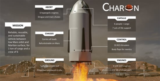
2]. Both of these mission concepts focused on the design of the transport vehicle itself. This article similarly describes a new design of a reusable Single-Stage-To-Orbit (SSTO) launcher operating between a Mars base and a spacecraft in Low Mars Orbit, with safety at the core of its design. This vehicle has been code-named Charon. Furthermore, the constraints the design would put on the base are analysed. This way, a more complete analysis can be performed on whether the vehicle design is realistically feasible or not.
This transportation method would have to adhere to certain key requirements. Among the 80 requirements that have been defined for this mission, the most important were the following three. First, the design shall be capable of transporting a payload of six humans and 1200 kg of cargo. Secondly, for the design to be sustainable, any parts that are not designed to survive the entire operational lifespan of the vehicle, and any consumables used during its nominal mission, shall be producible on Mars through in-situ resource utilisation (ISRU). Finally, since the vehicle will be used to transfer humans, it shall have a SL-LOC probability of 0.5%. This number has been based on the Crew Dragon Loss of Crew probability of 1 in 270 [
3].
In this article, first a mission profile is created, which describes how the vehicle reaches Low Mars Orbit, docks to the orbiting vehicle, and lands again. This is followed by a preliminary technical design of the vehicle and its subsystems, while adhering to the key mission requirements and focusing on reliability and maintainability. With the vehicle designed, the budgets for mass, velocity, and cost are calculated, and a failure analysis is performed. Finally, a conclusion is made on the feasibility of the design, in the case that the vehicle would be operational at the start of 2040. This is done by looking at the requirements it imposes on the Mars colony, such as the amount of fuel the colony would need to produce or the infrastructure required to service the vehicle.
2. Materials and Methods
This section aims to describe the methodology used in this article. A detailed mission profile of the Single-stage Reusable Vehicle (SRV) has been designed, including the ascent, rendezvous, and re-entry. With this, the technical design of the vehicle and its subsystems could begin. The latter has been made mostly with Python (PSF, US). The different scripts that have been written to produce the various simulations and to design different subsystems can be accessed at a public GitHub repository [
4]
https://github.com/gaffarelj/DSE-Mars-SRV; accessed on 16 December 2020. Further, the technical report detailing all aspects of this mission and of the subsystems that were designed can be demanded to the corresponding author of this article.
Regarding the technical design of the vehicle, a strong focus was put on creating a reliable and sustainable design which would be feasible in the near future, in 2040 at the earliest. Therefore, the technology used during the design was limited to that with a minimum Technology Readiness Level (TRL) level of 4. Furthermore, the reliability played a core role during the subsystem design. Critical failure modes were mapped out, resulting in an increased redundancy, and a risk mitigation strategies study.
From the vehicle design, the operations and consequent required infrastructure can be analysed, so as to reflect on when such a vehicle could be used on Mars, given how developed a Mars base is required to be. Finally, the design can be analysed to show how reliable it is, its mass breakdown and its velocity budget.
3. Results
3.1. Mission Profile
For the vehicle mission to succeed, the mission profile needs to be established. As such, an orbital node is defined and the flight path is determined. The orbital node height is 500 km above the Martian surface. This node can either be a Mars planetary space station, another big transport vehicle coming from Earth, or another. The altitude of the node has been arbitrarily selected as a high estimate of where such space station or big transport vehicle would be placed around Mars.
Paths for ascent, rendezvous and reentry are simulated. This provides a better understanding of the loads experienced by the vehicle during these phases of the flight, the amount of fuel needed, as well as the control and heating of the vehicle during the mission.
Figure 1 shows the mission profile of Charon as it was determined through the analyses.
The maximum mission duration was chosen to be four days, keeping power and life support requirements in mind. Due to the favourable location, it is assumed that the Mars base will be located at Deuteronilus Mensae, lying at an altitude en latitude of 42.5 and 25.5, respectively. The inclination of the node is defined to be 42.5 accordingly. After the ascent phase, the vehicle reaches its phasing orbit at roughly 42.5 inclination and 100 km higher than the node orbit. Following this, it will start far range rendezvous by undergoing transfer to the node after which close range rendezvous is initiated and docking is completed. When returning, the vehicle performs an insertion burn with the main engines for controlled entry into the Martian atmosphere. This is followed by atmospheric deceleration and propulsive landing. The separate stages of the mission will be detailed further next.
3.1.1. Ascent
With the vehicle leaving the launch pad, a trajectory has to be followed up to a phasing orbit, after which rendezvous and transfer manoeuvres are initiated. For Charon, a direct ascent was chosen, meaning that the vehicle follows a vertical flight for the first 100 m after which it starts pitching in a gravity turn that results in the vehicle reaching the phasing orbit. The gravity turn is designed in such a way that the maximum acceleration experienced by the crew corresponds to a maximum of four Martian-g’s. The optimum ascent trajectory was determined by generating both a 2D point-mass simulation as well as 3D rigid-body simulation. The code written for these simulations is publicly available on GitHub [
4]. The ascent profile, with the most important phases and altitudes that the vehicle goes through, can be seen in
Figure 2. Moreover, the gravity field of Mars has been simulated using values of Sharaf and Selim [
5], and the Martian atmosphere has been simulated following the same exponential model as Zhao and Li [
6] (p. 3).
3.1.2. Rendezvous
After the ascent phase, the vehicle is inserted in the phasing orbit at an altitude of 609.74 km above Mars, and Charon aligns with the node for a duration of a maximum of two orbits. After this, a transfer manoeuvre is executed towards the node orbit during which close proximity phases are initiated with a proximity of 1000 m from the node. Here, relative navigation is used such as full control, provided by the Reaction Control System (RCS). Close proximity phases are simulated in terms of relative motion such to accurately determine the required control from the RCS. Here solely RCS engines are used for control. The three phases depend on the relative distance to the node; Proximity A from 1000 m to 250 m, Proximity B from 250 m to 30 m, and Docking from 30 m to 3 m, as mentioned by Wertz and Bell [
7].
The trajectory strategy is considered to be a straight line along the local orbital velocity vector of the node, Vbar. However, Vbar allows for hold points [
8]: points in the trajectory where time-independent stops are possible as the vehicle has zero relative velocity compared to the node. These points are reached in between each docking phase. Here the vehicle stops and a go-no-go decision is made where docking can be continued, paused or cancelled if necessary. Finally, as docking cameras are used for relative navigation, there is a lower boundary on the lighting conditions in order to have sufficient accuracy. In order to operate during periods of no lighting, during eclipse, guidance lights are activated on the node.
3.1.3. Reentry
The reentry process starts when Charon detaches from the orbital node. The engines are brought in alignment with the flight path for the reentry insertion burn. This brings the vehicle into an orbital trajectory that allows for controlled entry into the Martian atmosphere. During atmospheric reentry the vehicle maintains a constant angle of attack of 50 to maximise drag. The control is achieved using a combination of the RCS system and a two piece body flap allowing for pitch and roll control. At an altitude below 20 km the vehicle is rotated for the final landing burn. This altitude is chosen such that the burn can be performed as late as possible, in order to rotate the vehicle at a lower velocity and minimise the required fuel. Here, three of the main engines at max thrust are used to reduce the remaining descent velocity to below 6 m/s to ensure a safe landing. Using three engines ensures low g-forces on the crew, around 2 g, for landing.
In order to fully characterise the reentry profile, a three dimensional trajectory simulation has been made, using equations of motions similar to Jiang and Li [
9] (p. 2). This includes an aerodynamic heating analysis, as well as a Monte Carlo simulation to assess the possible variation in impact location in the event of vehicle loss. The results of this simulation can be seen in
Figure 3. The standard deviations are based on the results of the Kalman filter, which will be discussed later. These scattered impact points were used to construct a required manoeuvring envelope for the vehicle.
3.2. Vehicle Subsystems
Having established and analysed the mission profile, all of the vehicle subsystems are designed and integrated as to ensure a successful flight. Each subsystem is designed within their corresponding constraints, resulting from the defined system requirements. Consequently, a requirement compliance check has been performed for all subsystems. The capsule layout is shown in
Figure 4, along with the layout of Charon in
Figure 5.
3.2.1. Life Support
The purpose of Charon’s first subsystem, the life support, is to provide all of the necessary elements to keep the crew well and alive during nominal and non-nominal conditions. This includes food and water supplies, as well as atmospheric and thermal control. This can be seen in purple on
Figure 4. The nominal mission lasts four days, based on the maximum mission length. The off-nominal mission duration is of seven days, including the time required for rescue.
Firstly, according to a NASA report [
10], each adult crew member needs 1.62 kg of water daily, as well as 1.77 kg of dry food, with an additional 0.8 kg of water to hydrate it. Having six crew members, for a maximum off-nominal duration of seven days, and using a safety margin of 50%, there is a need for a total of 152 kg of water and 111 kg of dry food. However, as to save weight on the capsule, only 20 kg of water will be packed at lift-off. The remainder will be produced by the capsule’s hydrogen fuel cells.
Secondly, the composition of the atmosphere is ensured via a physical filter. Having a mesoporous silica at its centre, the 2 nm pores [
11] let the O2, Ar, and N2 particles go through it, while blocking the harmful CO2, CH4 and NH3, creating a breathable atmosphere as close as possible to the one found on Earth, being optimum for the crew. This filter is in principle producible on Mars, and can be used for many flights, in contrast with a conventional chemical filter that has to be regularly renewed. Using a 30% safety margin on the required O2 supply and doubling it for redundancy, three tanks of three litres are required, storing the oxygen at a capsule temperature of 20
C and a typical pressure of 13 MPa [
12].
Thirdly, with regard to the thermal control, each crew member will produce between 100–120 W of heat during the flight [
13]. Insulating the capsule with a foil similar to the Coolcat 2 Ni from Ruag (Swiss Confederation, Bern, Switzerland) [
14] that has a heat flux of 3.4 W/m
, and with the capsule surface being of 45 m
, the capsule would continuously lose 153 W of heat. Having at least 2 crew members, the capsule will thus need to be actively cooled by the radiator already used to cool the fuel cells.
Finally, there is no need for a radiation shield. Indeed, according to the Ames Research Center [
15], a radiation shield is recommended for a mission of more than 30 days, whereas the maximum off-nominal mission duration of Charon is seven days. Even though the crew travelled from Earth to Mars for longer than 30 months, it is assumed that they are shielded from radiation for that duration. The last off-nominal seven days of their trip to Mars can thus be done without radiation shield.
3.2.2. Abort
Following Life Support, the Abort subsystem is critical to the crew safety, as it is the last chance to escape the vehicle, should it become hazardous. Charon’s flight has been separated into multiple flight phases, each associated with a different abort mode. This makes the vehicle the first in its class to consider safety as strongly. Further, the systems used to accelerate the capsule away from the vehicle, then decelerate it to the ground, have been investigated and sized. Finally, a discussion is made about how many vehicles are required on Mars at the same time, as to rescue the crew after an abort.
Abort Modes
Simulations have been carried to determine the feasibility of the abort system on one hand, and to size the abort engines and parachutes on the other. The code of these simulations is publicly available in the abort folder of the GitHub repository [
4].
The first abort mode is between lift-off and Mach 8, as required from the Apollo abort modes [
16] (p. 7). At that point, the ascent simulation showed that the capsule will be at a altitude of 38 km, travelling at a velocity of 1.65 km/s. Initiating the abort at Mach 8 will add 225 m/s to this, in 3 s, as required from the Orion abort protocol [
17] (p. 15). The altitude and velocity of the capsule from abort at Mach 8 to landing can be seen in
Figure 6.
To decelerate after abort, drogue chutes will deploy at a dynamic pressure of 805 Pa, 106 s after abort. 28 s later, the main chutes will deploy, at a dynamic pressure of 922 Pa. This ensures that the maximum acceleration felt by the crew will be of 6
. Finally, the abort engines will fire one last time to do a propulsive landing, decelerating the capsule from 95.5 m/s to 0. The abort system is designed to still have an additional 80 m/s available if required. The simulation of the loads and dynamic pressures on the capsule during this abort mode can be seen in
Figure 7.
The second abort mode is from Mach 8 to the phasing orbit. During this flight phase, another simulation showed that the capsule will require 3.47 km/s to get to an orbit at an altitude of 175 km. This orbit being the minimum one from which the capsule can stay 4 days before decaying back into the atmosphere, according to the simulation shown in
Figure 8. This would require the abort system to carry an additional 12,450 kg of propellant. This is deemed too high, thus no abort after Mach 8 is possible. This is acceptable, as the need for an abort system after Mach 8 is considerably lowered as the structural load will be considerably decreased, and the engines will have performed nominally for 86 s.
The third abort mode starts when Charon enters the phasing orbit, and stops when it is 1 km away from the station. In this flight phase, the vehicle will always be pointing away from the station, so that, if need be, the abort engines can instantaneously fire and push the capsule away from the vehicle. To ensure that the station or main spacecraft at 500 km altitude orbit does not suffer from any damage caused by a catastrophic failure of the vehicle, the orbit of the LMO node will be increased as soon as the abort has been initiated. Later, another Charon docked to the LMO node would rendezvous with the capsule containing the crew in orbit, and either rescue the crew and land on Mars, or dock to the LMO node.
The fourth abort mode starts when Charon completes its re-entry burn. If need be, the abort system then needs to get the capsule to an orbital altitude of at least 170 km. This is still possible for the abort system up to 19 min after the reentry burn.
Finally, the fifth abort mode starts during the end of reentry, when the thermal heating gets below 2 kW/m. Charon is required to always point above the horizontal, so that the abort engine can accelerate the capsule away from the vehicle. Then, the parachutes and abort engines will decelerate the capsule, as in the first abort mode.
Abort Propulsive System
From the different simulations carried out earlier, it has been determined that the abort engines must provide an acceleration of 79 m/s
. This corresponds to 8 g
for a duration of about 3 seconds. While this could injure one or more crew member, such acceleration is non-lethal [
18]. This acceleration is lower than the 11 g
of abort with Orion [
17]. After multiple iterations, the capsule mass was computed to be 14,200 kg. Hence, the abort engines must provide 1065 kN of thrust. To lower the footprint of the abort engines, they are placed two by two around the capsule, as seen in
Figure 9. They are also angled at 20
, so that their exhaust does not interfere with the frame of the capsule. Because of this angle, each abort engine shall provide 189 kN of thrust.
The combustion chamber and nozzle of these abort engines has been sized, and their performance simulated using the Rocket Propulsion Analysis software (Alexander Ponomarenko, Germany) [
19]. Using Hydrazine and Nitrogen Peroxide, these engines each of a mass of 119 kg, have a vacuum
of 259.6 s, a mass flow rate of 74.4 kg/s, and each provide the required 189 kN of thrust.
To be able to fulfil the most demanding abort modes, as well as land propulsively, the capsule will thus have 2336 kg of propellant, from which 64% is the hydrogen peroxide, and the remainder is the hydrazine.
Finally, the abort engines use a pressure-fed cycle, using Helium at 30 bar, and the propellant is self-igniting. These design choices both make the abort engines more reliable.
Crew Rescue
According to the simulations made, in the worst case scenario of abort at Mach 8, the crewed capsule will land at 3020 km from the launch pad. As imposed by life support, they need to be rescued within 3 days. A rover departing from the base would thus need to move at a velocity of 32 km/h, 25% higher that NASA’s concept for a crewed rover [
20].
While a rover could be put beforehand in the approximate landing zone of the capsule after abort, another Charon vehicle could otherwise launch from the base and land next to the stranded crew. Then, it would launch again and bring the crew back to the base. Such mission would require 87,700 kg of propellant, well within the capacity of the vehicle. The simulation of this suborbital flight can be seen in
Figure 10. This confirms that such a rescue mission is possible.
3.2.3. Power
The power subsystem was designed such that it could provide continuous power to the entire vehicle for a maximum of four days, which is the maximum mission duration, and power the capsule for an additional three days, in case of an abort. These duration were discussed in the life support section. Taking this into account, the capsule and the propulsive stage are both equipped with their own separate means of power generation.
When estimating the power requirements of the vehicle, data from other manned launch vehicles was used, such as the space shuttle and Orion. The active heating and cooling is quite minimal in the life support system, which decreased the estimated power requirements of the vehicle. The entire vehicle would have a maximum power requirement of approximately 8 kW, with the capsule on its own having a power requirement of 6 kW, in case of an abort.
The propulsive stage is equipped with two combustion engines which consume boil-off from the main propellant tanks to generate power, making use of the Integrated Vehicle Fluids concept [
21]. One engine is sufficient to power the entire vehicle, with the second engine being there for redundancy.
For the capsule, two Proton Exchange Membrane (PEM) fuel cells [
22,
23] take fuel from liquid oxygen and liquid hydrogen tanks, creating power for the capsule, as well as drinking water for the crew. Again, one fuel cell has the capacity to power the whole capsule and the other fuel cell is there for redundancy. In total, approximately 25 kg of liquid hydrogen and 201 kg of liquid oxygen is stored in the capsule for the fuel cells.
3.2.4. Communication
Regarding the communication subsystem of the vehicle, it is critical for the safety of the crew that a communication link with either the base or the node is available at all times during the mission. This means that there must be a system of relay satellites available. This is achieved with a constellation of three satellites. These would be in a similar inclination as the orbital node and at an orbital radius of 10,000 km around Mars. This orbit is lower than a Mars stationary orbit, as the distance between the vehicle and the satellites would otherwise cause the space loss to be too high, leading to the communication link not fulfilling the required BER. The Bit Error Rate (BER) requirement is set at
, which is slightly stricter than the typical requirement of
[
24]. This is done to mitigate the additional noise that will be generated when the signal is cross linked from Charon to the relay satellites and the ground station.
Regarding the communication of the launch vehicle itself, a similar system as that of the space shuttle is used [
25]. Four omnidirectional S-band antennas are placed around the capsule [
26], underneath the heat shield. This gives full coverage around Charon during its mission. With this hardware, the communication subsystem can uphold a data rate of 20 Mb/s. The link budgets for the downlink of the spacecraft can be seen in
Table 1 for all three different communication links. Because the uplink can by closed by increasing the power output of either the ground, relay or orbital node transmitters, it was not analysed when sizing the communication system of Charon. The ground station is located at the Mars base and is assumed to have an antenna diameter of 6 m. The antenna diameters of the relay satellite and the orbital node are assumed to be 3 m and 2 m, respectively.
3.2.5. Guidance, Navigation & Control
A vital part of the system is tracking of the vehicle during flight, enabling navigation of the vehicle and its control. Sensors are used for tracking along with a set of thrusters to provide full control. Throughout the entire flight, inertial sensors are used for positioning. Additionally, a surface based radar system is used during ascent, reentry, and phasing. Furthermore, star tracking cameras are also used during phasing. During docking, relative navigation through cameras is used. They are usable with sufficient accuracy within 2000 m of the node. Finally, for increasing reliability, landing cameras are used during landing. An Extended Kalman Filter has been used to simulate the state determination accuracy for all flight phases.
For the reaction control system, control over 6 degrees of freedom is required to execute the pitching, rolling, lateral acceleration, and disturbance corrections that are necessary to complete the mission profile. Thus, a full thruster configuration is used with 32 thrusters providing instantaneous and decoupled control and 6 Degrees of Freedom. An extra thruster is used for reentry pitch control. Decoupling adds weight but provides a lower control complexity and more redundancy. After sizing the RCS, the propellant is chosen to be mono-prop hydrogen peroxide. This choice results from a trade-off on performance, throttleability, complexity, and sustainability [
27]. A visualisation of a set of thrusters can be seen in
Figure 11. Each engine weighs in at 4 kg, with a tank structural mass of 40.2 kg for each of the two propellant tanks. The total propellant is estimated to be 1243 kg for all manoeuvres plus a redundancy.
3.2.6. Aerothermal
During the reentry phase of flight, the vehicle experiences extreme heating from the Martian atmosphere at hyper-sonic velocities. With the vehicle assumed to be inclined at
during reentry, the stagnation point heat flux was calculated and assumed to be a uniform heat flux over the entire flow-facing surface. This is a reasonable assumption according to Fay and Riddell [
28]. To size the Thermal Protection System (TPS), the material is assumed to have similar properties to the Space Shuttle LI900 (Lockheed Missiles and Space Company, Sunnyvale, US) tiles [
29]. However, these tiles are known to be hard to refurbish. The design is thus only based on their properties, but it is assumed that newer easier to replace tiles are nowadays available [
30]. This resulted in a material thickness of 6 cm at the underside, while the top side has a thickness of 2 cm.
Furthermore, thermal control in orbit due to the vehicle radiating heat out, heat from Mars’ albedo, and IR radiation required consideration of heating systems on the vehicle. It was determined that with a minimum internal temperature of 220 K the structure is not damaged, however, some additional heating is required for the various electronic components.
For the stability and the manoeuvrability of the vehicle some aerodynamic surfaces and body flaps are included in the aerodynamic shell of the vehicle. The body flaps were sized such that the distance between the centre of pressure centre and centre of gravity is maximised. The aerodynamic shell can be seen in
Figure 12, together with the wings, flaps, and the thickest part of the TPS in black.
3.2.7. Structures
The vehicle loading and materials required to support all vehicle subsystems are investigated, the mass moments of inertia are computed and the vehicle is sized. The main structural elements of the vehicle can be seen in
Figure 13. For most of the structural components, Aluminium Alloy-QQ-250/4 is used because the components of this alloy are present on the surface of Mars, and therefore can be reproduced in-situ assuming the presence of mining equipment and metallurgical infrastructure [
31]. This could allow for repairs to still be carried even when some parts cannot be shipped from Earth fast enough.
The crew and cargo compartments are sized. They are both located in the pressurised volume of the capsule, capable of bringing six people on board. This pressurised volume has been sized by computing the stress in a cone with cutouts for the window, docking port, and loading hatch. It is pressurised to 1 atmosphere. Such computation method has been taken from [
32].
The docking mechanism was selected to be Androgynous Peripheral Docking System (APDS) with some slight adjustments to account for the different mass of the chaser and target, as suggested by the International Docking System Standard [
33].
The main material for the oxidiser and fuel tank is IM7-977 Carbon Epoxy Composite [
34]. For the tank design, a common bulkhead is used, with the fuel tank being reinforced by aluminium stiffeners. The relevant stresses in the tank structure have been computed following methods from Sforza [
35]. Together, the tanks have a height of 8.485 m and a diameter of 6 m. The skin also has a minimum thickness of 2.9 mm.
It was determined that four landing legs would be required for Charon to be able to sustain the loading during landing. These were designed according to a dynamic load analysis, using equations from Akin and Thompson [
36,
37]. Each leg is sized such that it would not fail under the off-nominal condition where one leg hits the ground before the rest at a vertical speed of 16 m/s, which would result in a maximum normal stress of 293.8 MPa.
Finally, a vibrational analysis of the vehicle has been carried. Approximating the Young’s modulus of the vehicle by a combination of the one of Aluminium and the Bulk modulus of Methane, and taking the mass of the vehicle into account, it is taken to be 13.87 GPa. The natural frequency in the longitudinal and lateral direction are then computed to be respectively of 78.19 and 14.81 Hz.
3.2.8. Propulsion
The nine engines aboard Charon were arranged in a symmetrical octa-web configuration, and each engine’s performance is such that five engines could supply enough thrust for nominal operations. This allows for a two-engines-out capability. This configuration can be seen in
Figure 14.
For a young colony positioned to be established within the next two decades, the infrastructure to extract, refine, and handle the consumable resources required for a launch vehicle is expected to be quite underdeveloped. Liquid oxygen and methane are producible relatively simply, and a LOX/LCH4 combination provides the best trade-off between performance, handling, size and structural weight of the propellant tanks, and experience within the field of rocketry.
To maintain reliability over a ten year period, pre-burners were excluded from the design, and instead it was decided to drive the turbines using the methane as in an expander cycle.
With a 200 bar chamber pressure and a mixture ratio of 3.6, the chamber temperature reaches 3400 K. To cool down the chamber walls and the nozzle, the liquid methane is pumped through channels within the skin from the injector down to the nozzle exit, meanwhile a layer of liquid methane is injected along the combustion chamber walls. This combination of regenerative and film cooling will need to be validated during hot-fire tests of the engine.
All told, each engine can produce a thrust of 310 kN, at a specific impulse of 371 s, with a total exit area of 0.877 m
and an area ratio of 125. The high specific impulse is notable, and is thanks to the high chamber pressure; overall the Isp is justified given recent high Isp methalox expander designs by JAXA [
38] and ESA [
39].
3.3. Operations
With the preliminary design of the vehicle finished, the logistics of the mission operations will be detailed further in this section.
3.3.1. Life Cycle
As mentioned, Charon does not transport people from Earth to Mars, but acts as a ferry between an orbital node and a Mars base. For the analysis of the life cycle of Charon, a high demanding scenario is assumed, where up to a 100 people and 50 tons of cargo must be transported from Low Mars Orbit to the surface of Mars in each synodic period. It is expected that 30 Charon flights will be required to transport all the people and cargo on the node to the base, keeping some extra possible flights in reserve.
The exact number of launches before extensive refurbishment is required is difficult to estimate without extensive fatigue testing of structures and the engine. An assumption is made that one vehicle will be able to perform 10 launches with only quick visible checks and refuelling. These quick refurbishments will be performed at the maintenance facility by a crew which is assumed to have the necessary expertise to perform the maintenance. Further requirements of the maintenance facility are detailed in the infrastructure section. This roughly corresponds to 4000 seconds of total Charon engine burn time. This is deemed feasible given existing engines are already designed to operate for such long burn times, such as the Vulcain engine family (Safran Aircraft Engines, France) with an operational life requirement of 6000 s [
40]. This means at least three vehicles should be stationed on Mars, which would give each vehicle an operational period of 260 days. With regards to rescue missions, it will be required that either a Charon vehicle is docked at the node at all times or either a vehicle different than Charon is available in orbit, to rescue a crew that is stranded in orbit. In the most optimal situation, an additional vehicle will be available in the maintenance facility. It could then be scrapped in case certain parts are urgently required for other vehicles maintenance. This would bring the total fleet size to five vehicles.
3.3.2. Launch from Earth
Since Charon is designed to work most efficiently in the Martian environment, it is not able to launch itself from Earth to Mars. Since the vehicle will be built on Earth, it needs to be carried out of the Earth by a launcher with large payload capabilities. One option is to split the vehicle in two parts, and have each part be launched into orbit aboard a heavy launcher such as SLS (NASA, US) or Starship (SpaceX, US), after which the vehicle is assembled in orbit. How exactly the vehicle will be launched from Earth is to be detailed at further stages of the design.
3.4. Infrastructure
For the vehicle to fulfil its requirements, certain infrastructure must be in place on Mars. This is described in this section.
3.4.1. Mars Base
With the preliminary design of the Charon vehicle known, an analysis can be made of what requirements the Mars base should fulfil in order for the Charon fleet to operate.
Base and Launch Pad Location
The Martian base is to be located in the Deuteronilus Mensae valley due to its scientific interest regarding martian geology, hydrology and climate science, and its abundance of subsurface water resources [
41]. While Charon does not need a launch tower to launch, it does need some infrastructure due to the large possible impact of dust particles on the Martian vehicle. Therefore, dust and safety of the Martian habitat are two topics mainly considered for the launchpad. To this end, three launchpads should be built on the side of the central uplift of an impact crater in order to direct flames and debris downwards from a slope [
42]. These pads could be constructed from sulfur concrete produced on Mars [
43].
Crew and Cargo Transportation and Discharge
In order to get the crew and cargo out of the vehicle after landing, the crew will make use of a simple ladder while the cargo is transported out of the vehicle by a crane. The crew and cargo are then transported by a minimum of three transport vehicles each having the capacity for four people and 350 kg of cargo, thus leaving room for members of the launch support crew. The dry vehicle is to be transported by the crane to the maintenance facility.
Maintenance Facility
The vehicle has to be refurbished in a maintenance facility to protect it from the Martian environment. This facility shall be capable of suspending a rocket to allow for engine disassembly and have all tools necessary for a fast maintenance. Moreover, such facility has to be within an aforementioned crater, to allow for fast transportation to and from the launch/landing pads, while also needing a connection to a source of power. For this reason, the facility is planned to be located in the south-east of the crater, right next to a mountain, while also being close enough to a power plant somewhere between the crater and the base. The facility is planned to be at least 50 meters wide, to contain the vehicle in a horizontal position, while also having enough room to disassemble the engine and perform any work necessary.
Propellant Manufacturing
To manufacture the propellant required to complete a mission under nominal conditions, multiple resources must be obtained from the Mars environment. In a single launch, Charon will use up to 38 tons of methane and 143 tons of oxidiser, including boil-off and thrusters. Water mining facilities and a carbon dioxide capturing system must be available to acquire the necessary reactants to create the propellant. First, water must be mined in order to produce H
2 and O
2 through water electrolysis. The hydrogen is used in combination with the captured carbon dioxide in the Sabatier reaction, to produce methane and water, as mentioned by Chen et al. [
44] (p. 6). For the first launch propellant production, 170 tons of water must be mined, and 104 tons of carbon dioxide must be captured from the atmosphere to produce enough propellant. Because of the production of water after the Sabatier reaction, the amount of water to be drilled for later propellant production is reduced to approximately 76 tons.
Mining Equipment
Finally, the Martian base is required to possess the equipment needed for propellant and resources mining. For instance, equipment to mine water shall be present on Mars before Charon arrives for propellant production. Further, tools to mine the top layer of the Martian surface is required as to produce the Aluminium used to repair some parts of the vehicle. This is the main reason why Aluminium Alloy-QQ-250/4 is used as the metal in the main structure of Charon as much as possible.
Energy Requirements
The general power requirement for the different processes associated with the manufacturing and storing of the propellant is summarised in
Table 2. This is the constant required power in the case of one launch over a 130 days period. The power required is computed based on the energy required to produce each of the propellant constituents, as well as the energy required to transform the raw mined materials to the products used to create the propellant constituents. In addition, the efficiencies of the different transformations has been taken into account. Finally, the Sabatier reaction releases energy, which thus has a negative contribution to the propellant manufacturing power budget. For the process of water electrolysis, which is the most power consuming process, it is assumed to occur with 286 kJ/mol and a 75% efficiency, which can be assumed for steam reforming electrolysis [
45].
There is thus a need for a total of 1.02 MW of power constantly for one launch in 130 days. Moreover, considering electrolysis, oxygen liquefying and carbon dioxide capture to be electrical processes, 972 kW of this power needs to be electrical, while 50 kW is thermal.
The 1 MW electrical power requirement makes one consider a scaled-back nuclear power plant to provide the required energy. While small scale projects exist as nuclear reactors on the Martian surface [
46], mission concepts with a megawatt-rated nuclear power plant were suggested a long time ago—both by the Soviet Union [
47] and NASA [
48]. Such a reactor would require 1.1 kg of Uranium-235. This could be either imported from Earth or found on Mars, where, although no hard-proven data exists, mathematical models predict an abundance of Uranium resources, as it is predicted that the formation of found radioactive potassium traces are from Uranium [
49]. Therefore, while additional studies are needed on the feasibility of uranium mining on Mars, a nuclear reactor of such scale is a realistic and highly probable concept for the Martian base, as it is easier to construct and operate than thousands of square meters of solar arrays. In the case that 10 launches would occur every 260 days, this nuclear reactor would have to be significantly scaled up in order to produce enough power.
3.4.2. Satellite Constellation
As previously discussed, some relay satellite constellation must be in place to have continuous contact with the vehicle during a mission. This can be achieved with a set of three relay satellites orbiting Mars at a radius of approximately 10,000 km and an inclination of 42.5. Since these satellites are only needed for required communication purposes and not for tracking, three satellites are sufficient.
3.5. Design Analysis
With the design complete and capable of fulfilling the mission profile, the resulting mass budget, velocity budget and reliability of the vehicle are investigated in this section.
3.5.1. Budgets
Firstly, the mass budget is critical to its design, as the mass is a key input to multiple subsystems. Because of this, Charon’s mass has been evaluated by a Class I method [
50], and multiple iterations have followed. In each iteration, the mass of the subsystems has been slightly altered. These iterations have been carried until Charon’s total mass was within 3% of the previous iteration. The final mass of all subsystems can be found in
Table 3. For all subsystems, the MGA was taken to be 20% [
51]. This margin covers the assumptions and uncertainties that were present throughout the subsystems design.
Secondly, the Delta-V budget directly follows from the mission profile, dictating Charon’s capabilities. The different velocity increments required trough out a flight of Charon can be seen in
Table 4.
Finally, the last budget that has been assessed is Charon’s cost. To do so, the Project Cost Estimating Capability software from NASA [
52] has been used. This software produced mass-based cost estimations for almost every subsystem and component of Charon, using reference data from a catalogue of similar NASA launch and crew vehicle projects. From it, Charon’s production cost adds up to
$548 M, the design and development cost to
$2687 M, the test and hardware cost to
$527 M, and the test operations to
$508 M. The production cost is recurring for each vehicle, and as mentioned in the life cycle discussion, five vehicles are required for optimal conditions. The production cost should then be multiplied by five, resulting in
$2740 M. In total, the complete cost of having a fleet of reusable SRVs on Mars, excluding the infrastructure in orbit and on the surface, is
$6462 M. Including the cost of the five contracted SLS launches (alternative launchers do not have a set price at the moment), and with a standard 60:40 Beta Curve for preliminary phasing of cost estimates over the project life-cycle [
53], the project cost was calculated to be
$13.8 billion over 18 years, with a peak annual cost of just over
$1 billion for the 15th year.
3.5.2. Reliability
The goal is to use Charon to transport humans on Mars for as long as possible—ideally for 75 launches over 20 years. This high number of launches from the same vehicle considerably increases the risk of LOM, LOC, and LOV. This means that the vehicle shall be designed to be as reliable as possible, explaining the need for redundancy in all critical subsystems, and the abort system capable of detaching the crew capsule from the rest of the vehicle, would the need arise.
Because of this, the SL-LOC probability is required to be below 0.5%. Over 75 launches, this combines to a LOC probability of 31.3%. While this is high, it is deemed acceptable, as the first missions on Mars, requiring such intense use of a single vehicle, are accepted to be of high risk. The SL-LOV and SL-LOM probabilities have been agreed to be of 2.5% and 5.5%, respectively.
In comparison, the Space Shuttle had a loss of crew probability of 1 in 100 [
54], and these vehicles were used for a maximum of 39 flights. The non-crewed reusable Falcon 9 Block 5 also has a landing failure rate of 5 in 59, or 8.5%, with a maximum of 9 flights for a single vehicle [
55].
To assess whether or not Charon fits these requirements, a fault tree analysis has been carried out. To build it, all different subsystem and part failures that would lead to either SL-LOC, SL-LOV, or SL-LOM have been listed. Then, taking into account the failure probability for a single component, the total number of components, and the number of redundant components, the combined failure probability is computed. Different components failure were also assessed. Individually, these would not lead to any failure, but combined, they would. For instance, a fire in the capsule would lead to LOM, as the fire would need to be suppressed, the crew put back in their pressurised suits, and Charon would get back to the base. An oxygen leak from the life support in itself would not lead to any loss, as the tank could be emptied, and the two other tanks in the capsule would still be usable. However, if a fire were to start combined with an oxygen leak, this scenario would lead to LOC.
This work of listing all components and scenario lead to 34 possible failures leading to LOM, 23 to LOV, and 38 to LOC. For the sensitivity analysis of the final LOM, LOV and LOC probabilities, the individual event probabilities were assumed to be normally distributed. The standard deviation was chosen to be
of the mean value. The calculation of the final probabilities was run 10,000 times, varying all parameters simultaneously according to their respective normal distributions. The computed LOM, LOV, and LOC probabilities are presented in
Table 5, along with their sensitivity analysis.
4. Discussion
Ease of maintenance and refurbishment instilled in the design philosophy the idea of modular systems, so that the vehicle could be more readily maintained, especially given the arduous nature of maintenance and refurbishment on Mars. In addition, the consumables of the vehicle will all be producible on Mars, allowing for continued operation without relying on Earth for launch-critical supplies. Furthermore, non-complex materials and additive manufacturing methods have been chosen such that component refurbishment is as easy and cheap as possible for the colony.
Moreover, a cargo-only version of Charon could be developed in more detail. This removes the need for the life support and abort system, shaving roughly 5500 kg off Charon, which could be used as payload mass instead.
The concept and technology development, as well as the preliminary design of Charon are all completed. This places the project at the start of Phase B. Still to be done in this phase are the completion of the technology, mock-ups delivery, specification and interface documentation, testing, and prototyping.
Relative to other concepts that could achieve the same goals, Charon is deemed relatively more safe and more robust. For instance, compared to Starship from SpaceX [
56], Charon possesses an abort system, enabling the capsule to quickly separate from the vehicle if need arises. While SpaceX claims that their vehicle will be safe enough not to have an abort system, it is deemed that the extra safety of having an abort system is of high importance. This becomes clear given the high number of flights that Charon will have to make between the Martian orbit and surface.
Because of this, it is recommended to use Starship for launches from Earth to Low Mars Orbit, and from there, use Charon to transport the crew and cargo in multiple flights between the orbiting stations to the Martian surface. This way, Charon would make the highest number of flights, while keeping the crew safe, and Starship would fly a large number of crew members from Earth to Mars.
Furthermore, compared to NASA’s similar Hercules vehicle concept [
1], Charon is capable of supporting six crew for up to seven days, higher than Hercules’ capability of four crew for three days. However, Charon’s payload capacity is only 1200 kg compared to Hercules’ 5750 kg for crew missions. Charon’s engines are similar to Hercules’, both using oxygen and methane, however Charon both has more engines (9 to 5), and thus a higher engine-out capability, and also has a higher thrust per engine. This necessitates approximately 10% more propellant per mission.
5. Conclusions
It is concluded that Charon is a reliable and sustainable vehicle for the given mission purpose of transporting crew and cargo between the surface and a low orbit node, promoting autonomy in the operations of a Mars colony. The program for its development and deployment is technologically and financially feasible.
However, it is a vehicle that requires significant prior infrastructure on Mars. This infrastructure is unlikely to be present by 2040. Development of Mars habitats, mining and manufacturing technologies are possible to complete within this time. However, the deployment of this equipment to Mars is likely to be too costly for a time frame of two decades, between 2020 and 2040.
Operations are thus unrealistic expect by 2040, and more likely starting around 2050. Considerable infrastructure is necessary on the red planet for such a vehicle to operate. This vehicle is thus deemed to be practical for operations only after a sufficiently developed colony has already been established on Mars.
Author Contributions
Article writing, J.G., A.K., M.F.; Ascent & Rendezvous, L.T.; Re-entry & Landing, J.N.; Aerothermodynamics, M.B.; Structures, M.L., D.A.; Propulsion, M.F.; GNC, L.L., W.H.; Communications & Power, A.K.; Ground Operations, L.C.; Life Support & Crew Safety, J.G.; System Integration, J.G., D.A., M.B.; Life Cycle, L.L.; Reliability, J.N., L.L., J.G.; Project Supervision, M.N. All authors have read and agreed to the published version of the manuscript.
Funding
This research received no external funding.
Acknowledgments
Special thanks to Henk Cruijssen and Lex Meijer from Airbus Defence & Space Netherlands for their invaluable feedback throughout the whole period of the Design Synthesis Exercise that led to this article. Thanks also goes to Barry Zandbergen and Erwin Mooij for their feedback during the Midterm Review of this project. Special acknowledgement goes to teaching assistant Anique Altena that helped the team organise itself, coaches Luis Laguarda and Stefano di Mascio for their feedback and ideas on improvement throughout the design process.
Conflicts of Interest
The authors declare no conflict of interest.
Abbreviations
The following abbreviations are used in this manuscript:
| APDS | Androgynous Peripheral Docking System |
| BER | Bit Error Rate |
| ESA | European Space Agency |
| GNC | Guidance, Navigation, and Control |
| Specific Impulse [s] |
| ISRU | In-Situ Resource Utilisation |
| JAXA | Japan Aerospace Exploration Agency |
| LMO | Low Mars Orbit |
| MADV | Mars Ascent/Descent Vehicle |
| MGA | Maximum Growth Allowance |
| NASA | National Aeronautics and Space Administration |
| PEM | Proton Exchange Membrane |
| RCS | Reaction Control System |
| SL-LOC | Single-Launch Loss Of Crew |
| SL-LOM | Single-Launch Loss Of Mission |
| SL-LOV | Single-Launch Loss Of Vehicle |
| SLS | Space Launch System |
| SRV | Single-stage Reusable Vehicle |
| SSTO | Single-Stage-To-Orbit |
| TPS | Thermal Protection System |
| TRL | Technology Readiness Level |
References
- Komar, D.R.; Tartabini, P.V. Lunar and Mars Ascent and Descent/Entry Crew Abort Modes for the Hercules Single-Stage Reusable Vehicle; Technical Report; National Science Standards; NASA: Washington, DC, USA, 2018. [Google Scholar] [CrossRef]
- Cichan, T.; Bailey, S.A.; Norris, S.C.; Chambers, R.P.; Ehrlich, J.W. Mars Base Camp; Lockheed Martin Corporation: Bethesda, MD, USA, 2017. [Google Scholar]
- Clark, S. NASA Clears SpaceX Crew Capsule for First Astronaut Mission. 22 May 2020. Available online: https://spaceflightnow.com/2020/05/22/nasa-review-clears-spacex-crew-capsule-for-first-astronaut-mission (accessed on 14 June 2020).
- Gaffarel, J.; Kadhum, A.; Fazaeli, M.; Apostolidis, D.; Berger, M.; Ciunaitis, L.; Helsdingen, W.; Landergren, L.; Lentner, M.; Neeser, J.; et al. GitHub Repository Containing Code Used to Design and Simulate the Mission of a SRV on Mars between the Surface and Low Orbit. 16 December 2020. Available online: https://github.com/gaffarelj/DSE-Mars-SRV (accessed on 16 December 2020).
- Sharaf, M.A.; Selim, H.H. Final state predictions for J2 gravity perturbed motion of the Earth’s artificial satellites using Bispherical coordinates. NRIAG J. Astron. Geophys. 2013. [Google Scholar] [CrossRef][Green Version]
- Zhao, J.; Li, S. Mars atmospheric entry trajectory optimization with maximum parachute deployment altitude using adaptive mesh refinement. Acta Astronaut. 2019, 160, 401–413. [Google Scholar] [CrossRef]
- Wertz, J.R.; Bell, R. Autonomous Rendezvous and Docking Technologies—Status and Prospects; SPIE Space Systems Technology and Operations: Washington, DC, USA, 2003. [Google Scholar] [CrossRef]
- Fehse, W. Automated Rendezvous and Docking of Spacecraft; Cambridge University Press: Cambridge, UK, 2003. [Google Scholar]
- Jiang, X.; Li, S. Mars entry trajectory planning using robust optimization and uncertainty quantification. Acta Astronaut. 2019, 161, 249–261. [Google Scholar] [CrossRef]
- NASA. Closing the Loop: Recycling Water and Air in Space; Technical Report; National Science Standards; NASA: Washington, DC, USA, 2012. [Google Scholar]
- Chaudhary, V.; Sharma, S. An Overview of Ordered Mesoporous Material; Technical Report; Indian Institute of Technology: New Delhi, India, 2016. [Google Scholar]
- King, D.; Decker, M. Gas Cylinders; Technical Report; StatPearls: Treasure Island, FL, USA, 2020. [Google Scholar]
- Stevens, M. Stanford University Human Body Heat as a Source for Thermoelectric Energy Generation. 27 November 2016. Available online: http://large.stanford.edu/courses/2016/ph240/stevens1 (accessed on 20 June 2020).
- RUAG Space GmbH. Thermal Insulation Products; Technical Report; Space Thermal Insulation Products; RUAG Space GmbH: Vienna, Austria, 2015. [Google Scholar]
- Sowa, M. Space Radiation Environment and Human Exploration; Technical Report; NASA Ames Research Center: Mountain View, CA, USA, 2017. [Google Scholar]
- Townsend, N.A. Apollo Experience Report—Launch Escape Propulsion System; Technical Report; NASA: Washington, DC, USA, 1973. [Google Scholar]
- Scogin, T.; Lacerda, M.; Marshall, J. Orion Capsule Launch Abort System Analysis; Digital Design and Manufacturing Assignment; Georgia Institute of Technology: Atlanta, GA, USA, 2016. [Google Scholar]
- Kumar, K.V.; Norfleet, W.T. Issues on Human Acceleration Tolerance After Long-Duration Space Flights; NASA/TM-104753; NASA: Washington, DC, USA, 1992. [Google Scholar]
- Ponomarenko, A. RP Software and Engineering UG, Version 2.0. 2015. Available online: https://www.rocket-propulsion.com (accessed on 2 June 2020).
- Granath, B. Mars Rover to Help Visitor Complex Kick Off New Exhibit. 13 June 2017. Available online: https://www.nasa.gov/feature/mars-rover-to-help-visitor-complex-kick-off-new-exhibit (accessed on 6 June 2020).
- Zegler, F. Development Status of an Integrated Propulsion and Power System for Long Duration Cryogenic Spaceflight. Technical Report. In Proceedings of the AIAA SPACE 2012 Conference & Exposition, Pasadena, CA, USA, 11–13 September 2012. [Google Scholar] [CrossRef]
- Warshay, M.; Prokopius, P.R. The Fuel Cell in Space: Yesterday, Today and Tomorrow. J. Power Sources 1990, 29, 193–200. [Google Scholar] [CrossRef]
- Jakupca, I. Fuel Cell Research and Development for Earth and Space Applications; NASA Glenn Research Center: Cleveland, OH, USA, 2018. Available online: https://ntrs.nasa.gov/citations/20190001140 (accessed on 26 May 2021).
- Wertz, J.R.; Everett, D.F.; Puschell, J.J. Space Mission Engineering: The New SMAD; Microcosm Press: Portland, OR, USA, 2011. [Google Scholar]
- Dumoulin, J. NSTS 1988 News Reference Manual; Kennedy Space Center; NASA: Merritt Island, FL, USA, 1988. [Google Scholar]
- Harris Corporation. Cavity-Backed Helix Antenna; AS-49034; Harris Corporation: Melbourne, FL, USA, 2010. [Google Scholar]
- Grafwallner, F. Hydrogen Peroxide (HP) Potential for Space Applications; ET-Energie Technologie Gmbh: Brunnthal-Nord, Germany, 2004; Volume 557. [Google Scholar]
- Fay, J.A.; Riddell, F.R. Theory of Stagnation Point Heat Transfer in Dissociated Air. J. Aeronaut. Sci. 1958, 25, 73–122. [Google Scholar] [CrossRef]
- Wei, H.N.; Friedmann, P.P.; Waas, A.M. Thermomechanical Analysis of a Thermal Protection System with Defects and Heat Shorts; Technical Report; Department of Aerospace Engineering University of Michigan: Ann Arbor, MI, USA, 2006. [Google Scholar]
- Uyanna, O.; Najafi, H. Thermal protection systems for space vehicles: A review on technology development, current challenges and future prospects. Acta Astronaut. 2020, 176, 341–356. [Google Scholar] [CrossRef]
- Metals Handbook, Properties and Selection: Nonferrous Alloys and Special-Purpose Materials, 10th ed.; ASM International: Materials Park, OH, USA, 1990; Volume 2.
- Baker, E.H.; Babcock, C.D.; Crawford, R.F.; Glassco, J.B.; Kaplan, A.; Kural, M.H.; Mayers, J.; Peterson, J.P. Buckling of Thin-Walled Truncated Cones; Technical Report; NASA: Washington, DC, USA, 1968. [Google Scholar]
- Kelly, S.M.; Cryan, S.P. International Docking System Standard (IDSS) Interface Definition Document (IDD); NASA: Washington, DC, USA, 2016. [Google Scholar]
- Zheng, H.; Zeng, X.; Zhang, J.; Sun, H. The Application of Carbon Fiber Composites in Cryotank; IntechOpen: London, UK, 2018. [Google Scholar] [CrossRef]
- Sforza, P.M. Manned Spacecraft Design Principles; Elsevier: Amsterdam, The Netherlands, 2016. [Google Scholar]
- Akin, J.E. Impact Load Factors for Static Analysis; Lecture Notes; Rice University: Houston, TX, USA, 2019. [Google Scholar]
- Thompson, B.S. ME 471 Engineering Design II; Michigan State University: East Lansing, MI, USA, 2005. [Google Scholar]
- Tsukano, T.; Nagao, N.; Tomaru, H.; Kuga, T. Component tests of a LOX/methane full-expander cycle rocket engine: Single-shaft LOX/methane turbopump. In Proceedings of the 8th European Conference for Aeronautics and Space Sciences (EUCASS), Madrid, Spain, 1–4 July 2019. [Google Scholar] [CrossRef]
- Roca, S.P. Model-based robust transient control of reusable liquid-propellant rocket engines. IEEE Trans. Aerosp. Electron. Syst. 2020, 57, 129–144. [Google Scholar] [CrossRef]
- Preclik, D.; Strunz, R.; Hagemann, G.; Langel, G. Reusability aspects for space transportation rocket engines: Programmatic status and outlook. CEAS Space J. 2011, 1, 71–82. [Google Scholar] [CrossRef]
- Head, J. Mars Human Science Exploration And Resource Utilisation: The Dichotomy Boundary Deuteronilus Mensae Exploration Zone. In First Landing Site/Exploration Zone Workshop for Human Missions to the Surface of Mars; NASA: Washington, DC, USA, 2015. [Google Scholar]
- Hammond, W. Space Transportation: A Systems Approach to Analysis and Design; American Institute of Aeronautics and Astronautic: Reston, VA, USA, 1999. [Google Scholar]
- Wan, L.; Wendner, R.; Roman, W.; Cusatis, G. A novel material for in situ construction on Mars: Experiments and numerical simulations. Constr. Build. Mater. 2016, 120, 222–231. [Google Scholar] [CrossRef]
- Chen, H.; Jonchay, T.S.d.; Hou, L.; Ho, K. Integrated in-situ resource utilization system design and logistics for Mars exploration. Acta Astronaut. 2020, 170, 80–92. [Google Scholar] [CrossRef]
- Kumar, S.; Himabindu, V. Hydrogen production by PEM water electrolysis—A review. Mater. Sci. Energy Technol. 2019, 2, 442–454. [Google Scholar]
- Hall, L. NASA Space Technology Mission Directorate. Kilopower. 28 January 2021. Available online: https://www.nasa.gov/directorates/spacetech/kilopower (accessed on 28 January 2021).
- Korolev, S.P.; Rocket and Space Corporation Energia. RSC “Energia” History. Available online: https://www.energia.ru/en/history/mars/chronology.html (accessed on 1 May 2020).
- Whitmarsh, C.L.; Whitmars, C.L., Jr.; Kerwin, P.T. A 1-Megawatt Reactor Design for Brayton-Cycle Space Power Application; NASA: Washington, DC, USA, 1969. [Google Scholar]
- Taylor, G.J.; Boynton, W.; Hamara, D.; Kerry, K.; Janes, D.; Keller, J.; Feldman, W.; Prettyman, T.; Reedy, R.; Bruckner, J.; et al. Igneous and Aqueous Processes On Mars: Evidence From Measurements of K and Th By the Mars Odyssey Gamma Ray Spectrometer. In Proceedings of the Sixth International Conference on Mars, Pasadena, CA, USA, 20–25 July 2003. [Google Scholar]
- Roskam, J. Aircraft Design Part I: Preliminary Sizing of Airplanes; Darcorporation: Lawrence, KS, USA, 1985. [Google Scholar]
- SRE-PA & D-TEC. Margin Philosophy for Science Assessment Studies; Ref. SRE-PA/2011.097/; ESA: Paris, France, 2012. [Google Scholar]
- Marshall Space Flight Center. Project Cost Estimating Capability (PCEC), Ref. MFS-33187-2. Available online: https://software.nasa.gov/software/MFS-33187-2 (accessed on 1 March 2020).
- NASA Executive Cost Analysis Steering Group. NASA Cost Estimating Handbook; NASA: Washington, DC, USA, 2015. [Google Scholar]
- Jones, H.W. NASA’s Understanding of Risk in Apollo and Shuttle. In Proceedings of the 2018 AIAA SPACE and Astronautics Forum and Exposition, Orlando, FL, USA, 17–19 September 2018; p. 5235. [Google Scholar]
- SpaceX Info. Launch List. 25 April 2021. Available online: https://spacex-info.com/launch-list (accessed on 25 April 2021).
- Space Exploration Technologies Corporation. Starship Users Guide, Revision 1.0. March 2020. Available online: https://www.spacex.com/media/starship_users_guide_v1.pdf (accessed on 1 March 2020).
Figure 1.
Charon mission profile.
Figure 1.
Charon mission profile.
Figure 2.
Ascent Profile.
Figure 2.
Ascent Profile.
Figure 3.
Monte Carlo simulation of 10 landing points.
Figure 3.
Monte Carlo simulation of 10 landing points.
Figure 4.
Layout of the capsule, with cutout.
Figure 4.
Layout of the capsule, with cutout.
Figure 5.
Layout of the vehicle, with cutout.
Figure 5.
Layout of the vehicle, with cutout.
Figure 6.
Simulated velocity (in red) and altitude (in blue) of the capsule after abort at Mach 8.
Figure 6.
Simulated velocity (in red) and altitude (in blue) of the capsule after abort at Mach 8.
Figure 7.
Simulated dynamic pressure (in blue) and deceleration (in red) of the capsule after abort at Mach 8.
Figure 7.
Simulated dynamic pressure (in blue) and deceleration (in red) of the capsule after abort at Mach 8.
Figure 8.
Simulation of the orbital decay after abort to orbit, showing the capsule velocity (in red) and altitude (in blue) over time.
Figure 8.
Simulation of the orbital decay after abort to orbit, showing the capsule velocity (in red) and altitude (in blue) over time.
Figure 9.
Abort System propulsion elements.
Figure 9.
Abort System propulsion elements.
Figure 10.
Simulation of a suborbital flight, as part of a rescue mission, showing the altitude of the rescue vehicle in red and the distance to the vehicle to be saved in blue, over time.
Figure 10.
Simulation of a suborbital flight, as part of a rescue mission, showing the altitude of the rescue vehicle in red and the distance to the vehicle to be saved in blue, over time.
Figure 11.
RCS sub-assembly.
Figure 11.
RCS sub-assembly.
Figure 12.
Aerodynamic shell with TPS and body flaps in black.
Figure 12.
Aerodynamic shell with TPS and body flaps in black.
Figure 13.
Main capsule and tank structure.
Figure 13.
Main capsule and tank structure.
Figure 14.
Main Engines with thrust structure.
Figure 14.
Main Engines with thrust structure.
Table 1.
Calculation of ratios and BER.
Table 1.
Calculation of ratios and BER.
| Element [dB] | Charon to Ground | Charon to Relay | Charon to Node |
|---|
| Transmitter power | 18.5 | 18.5 | 18.5 |
| Line loss | −0.88 | −0.88 | −0.88 |
| Transmitter gain | 0 | 0 | 0 |
| Point loss receiver | −0.12 | −0.12 | −0.12 |
| Space loss | −165.8 | −178.3 | −171.4 |
| Path loss | −0.45 | −0.45 | −0.45 |
| Receiver gain | 40.2 | 34.2 | 30.7 |
| Boltzmann | 228.6 | 228.6 | 228.6 |
| System noise temp | −26.0 | −12.8 | −12.8 |
| Data rate | −73.0 | −73.0 | −73.0 |
| Margin | −2 | −2 | −2 |
| Eb/No | 19.0 | 13.6 | 17.0 |
| BER () | 0.0035 | 0.91 | 0.027 |
Table 2.
Propellant manufacturing power budget.
Table 2.
Propellant manufacturing power budget.
| Process | Power [kW] |
|---|
| electrolysis | 483 |
| Sabatier reaction | −27.8 |
| production | 0.03 |
| electrolysis | 0.60 |
| heating | 20.0 |
| heating | 13.3 |
| plant | 300 |
| capture | 190 |
| heating | 3.80 |
| heating | 0.01 |
| mining | 40.0 |
| Total | 1023 |
Table 3.
Mass budget.
| Subsystem | Mass [kg] | MGA Mass [kg] |
|---|
| Life support | 456 | 548 |
| Abort | 4259 | 5111 |
| Power | 1047 | 1256 |
| Communication | 31 | 37 |
| GNC | 1933 | 2320 |
| Aerothermal | 2399 | 2879 |
| Structure | 15,517 | 18,621 |
| Propulsion | 2621 | 3146 |
| Payload | 1200 | 1200 |
| Dry mass | 28,263 | 33,918 |
| Propellant mass | 137,886 | 164,807 |
| Wet mass | 166,149 | 198,725 |
Table 4.
Delta-V budget.
| Flight Phase | Delta-V [m/s] | MGA | MGA Delta-V [m/s] |
|---|
| Vertical flight | 92 | 25% | 114 |
| Gravity turn | 4533 | 5% | 4759 |
| Hohmann transfer | 46 | 5% | 48 |
| Inclination change | 289 | 5% | 304 |
| Re-entry insertion | 261 | 25% | 274 |
| Landing burn | 338 | 25% | 423 |
| Flight Reserves (5%) | 278 | 0 | 278 |
| Total | 5837 | 6% | 6200 |
Table 5.
LOM, LOV and LOC probabilities and their sensitivity analysis.
Table 5.
LOM, LOV and LOC probabilities and their sensitivity analysis.
| Parameter | LOM | LOV | LOC |
|---|
| 9.75E-3 | 1.2E-3 | 7.9E-4 |
| 1.737E-3 | 2.702E-4 | 2.184E-4 |
| 1.496E-2 | 2.010E-3 | 1.445E-3 |
| 4.539E-3 | 3.897E-4 | 1.348E-4 |
| Publisher’s Note: MDPI stays neutral with regard to jurisdictional claims in published maps and institutional affiliations. |
© 2021 by the authors. Licensee MDPI, Basel, Switzerland. This article is an open access article distributed under the terms and conditions of the Creative Commons Attribution (CC BY) license (https://creativecommons.org/licenses/by/4.0/).


 ,
, 


