Abstract
Testing of untethered subscale models, often referred to as subscale flight testing, has traditionally had a relatively minor, yet relevant use in aeronautical research and development. As recent advances in electronics, rapid prototyping and unmanned-vehicle technologies expand its capabilities and lower its cost, this experimental method is seeing growing interest across academia and the industry. However, subscale models cannot meet all similarity conditions required for simulating full-scale flight. This leads to a variety of approaches to scaling and to other alternative applications. Through a literature review and analysis of different scaling strategies, this study presents an overall picture of how subscale flight testing has been used in recent years and synthesises its main issues and practical limitations. Results show that, while the estimation of full-scale characteristics is still an interesting application within certain flight conditions, subscale models are progressively taking a broader role as low-cost technology-testing platforms with relaxed similarity constraints. Different approaches to tackle the identified practical challenges, implemented both by the authors and by other organisations, are discussed and evaluated through flight experiments.
1. Introduction
Downscaled physical models, also referred to as subscale models, have played an essential role in aerospace. Computational methods are slowly pushing experimental techniques towards a secondary role as verification or calibration tools, but physical models are still undoubtedly effective at revealing unexpected issues and providing confidence in estimations and assumptions. Wind-tunnel testing is probably one of the most established experimental methods in this field, but it sometimes fails to satisfy the requirements of modern aeronautical research and development: modern wind tunnel facilities are a scarce and costly resource, and are therefore not efficient for quick or iterative explorations of the design space during the initial stages of aircraft development. Further, the testing volume and capabilities are sometimes too limited to evaluate the integration of novel or immature technologies at a vehicle level. On the other hand, flight testing of full-scale, manned vehicles is, at this stage, often prohibitive in terms of both cost and risk. Testing of untethered subscale models, often referred to as subscale flight testing (SFT), could offer an affordable and low-risk alternative for gathering both qualitative and quantitative information.
The cost and capabilities of SFT have changed significantly thanks to factors such as the miniaturisation of mechatronic and communication systems, advances in rapid-prototyping and manufacturing techniques, and the availability of both software and hardware from the booming drone market. The development of sophisticated test objects at a wide range of scales can now be carried out even by organisations with limited resources. As a result, the practical threshold for engaging in scientific flight experiments with untethered models is becoming lower than ever before. It is, therefore, necessary to re-evaluate the SFT role and its potential within the contemporary aircraft research and development process.
Generally, free-flying subscale models cannot meet all similarity conditions required for simulating the exact, full-scale aircraft behaviour. In contrast to modern wind-tunnel facilities, neither the fluid properties nor its conditions can be adjusted at will when flying in the open atmosphere. The need for prioritising certain similarity aspects over others leads to a variety of scaling approaches and different areas of application. Some of these are sometimes misunderstood or oversimplified into a Reynolds number issue.
NASA has historically been one of the most frequently mentioned actors in the field of subscale flight testing. A 1979 Technical Paper by Wolowicz et al. [1] summarises the methods and the scaling principles that NASA’s subscale experiments were based on. In 2009, Chambers [2] presented an extensive historical review of NASA’s research activities involving subscale models from the 1940s to 2008. This publication describes how free-flying models, both remotely controlled and uncontrolled, were traditionally used in low-speed tests that are considered to be high risk, such as studying the dynamics of high angle-of-attack (AOA), stall, departure, post-stall and spin regimes. While of great historical interest, Chambers’ review does not provide a complete overview of the possibilities and limitations of modern SFT: it focuses mainly on one type of similarity – dynamic – and it blends open-air flight testing with tests inside wind-tunnel facilities. To the best of the authors’ knowledge, no other comprehensive review of the SFT method has been produced in recent years.
This paper aims to present an overall, up-to-date picture of SFT focusing on its main practical applications in contemporary aircraft research and development. An extensive literature review is carried out in order to reveal how SFT has been used in recent years as well as to synthesise its remaining challenges and practical limitations. Different approaches to tackle these challenges, implemented both by the authors and by other organisations, are discussed and evaluated through flight experiments.
2. Analysis
Some of the terms and principles used in this analysis may have different interpretations and uses in other contexts. For the sake of clarity, some definitions will be included here.
2.1. Definitions
Subscale flight testing (SFT) is defined here as an experimental method in which a downscaled, unmanned aerial vehicle is free-flown in the open atmosphere to obtain qualitative or quantitative information about a larger vehicle, a more complex system or a technology of interest.
This definition may differ slightly from other more open interpretations as it implies the following:
- The test object is flown unconstrained in the open atmosphere, which excludes flight inside wind-tunnel facilities.
- The test object does not have any crew on-board, independently of its control method.
- The test object represents a significantly larger, more complex system or technology and is therefore far from a final product, which excludes conventional flight testing of unmanned aerial vehicles (UAVs) but does not exclude technology demonstrators.
Downscaled UAVs are sometimes referred to as scaled models or even model aircraft. Note that, unless stated otherwise, the term model is used throughout this paper to designate a physical representation of an object, generally of a different size but connected by some type of similarity.
In this context, the concept of similarity or similitude represents an equivalence of properties or behaviour between two systems that are described by the same physics. Hence, it is a condition that depends on the nature of the physical phenomenon of interest and that can be defined via dimensional analysis [3,4]. In a purely mechanical interpretation at a general level, there are three types of physical similarity of relevance in this analysis:
- geometric similarity, which implies equivalence in shape and proportions;
- kinematic similarity, which implies equivalence in motion;
- and dynamic similarity, which implies equivalence in motion and forces.
The term scale factor refers to geometric similarity and it is typically used to represent a proportional ratio of linear dimensions of the model with respect to the original object:
Both geometric and kinematic similarity are typically used in aircraft development for communication and knowledge exchange, such as in technical drawings, flow visualisation tools or computer-aided design (CAD) environments. The quantitative analysis of the behaviour and performance of an aircraft generally involves the synthesis of multiple forces and motions, thus requiring dynamic similarity. This is the case for aerodynamics, flight mechanics, structures and other disciplines.
The non-dimensional parameters derived from dimensional analysis and that govern a particular scaling problem are commonly referred to as similarity parameters, scaling parameters or, more generally, scaling laws. The derivation of similarity parameters with useful applications in aircraft development is discussed extensively in references [1,5].
Focusing on the mechanical analysis of aircraft behaviour and performance in a typical atmospheric flight, the forces and moments are generally a function of the aircraft and fluid properties, the characteristics of the motion, and gravitational effects:
The nomenclature used here is described in the list of symbols at the end of the paper. All seventeen of these physical quantities involve three fundamental units (mass, length and time) and lead to fourteen different non-dimensional parameters defining similarity for flight dynamics for most of the practical cases. Following the dimensional analysis conducted in [1] and assuming fluid compressibility, these parameters take the following form:
where and are now also non-dimensional aerodynamic coefficients in the usual form of and respectively. These similarity parameters are described in Table 1.

Table 1.
Description of the similarity parameters found in Equation (3).
As a consequence of the diversity of requirements, physical limitations and technological limitations (for example, the gravitational field cannot be adjusted), it is generally impossible to design a subscale experiment in which all these similarity requirements are met simultaneously [1,2,5]. Instead, subscale experiments are designed to achieve a balance between fulfilling a subset of relevant parameters and relaxing others, depending on the phenomenon of interest. A particular approach to this similarity problem and the considerations around a specific scaled experiment can be referred to as a scaling method.
2.2. Common Scaling Methods
An extensive literature review was carried out with a focus on subscale experiments performed in the context of aircraft research and development. It was observed that most experiments with subscale models could generally be categorised into four different scaling methods, according to their main focus and the degree to which they fulfil similarity conditions. These are listed in Table 2.
Table 2.
The most common scaling methods used in SFT experiments can be grouped into four different types.
This general classification is indicative and by no means unequivocal. The boundaries between these methods are not always clearly defined, since many of the phenomena involved are closely interrelated. Some cases might fall partially in between or even outside these categories, although most subscale experiments can be related to at least one category.
2.2.1. Aerodynamic Scaling
The ultimate goal of aerodynamic scaling is to estimate the properties of the equivalent, real-world flow field around the full-scale vehicle. Note that although it is commonly assumed that this implies an accurate geometric similarity between the two articles, this is not necessarily required as long as the flow field produced is equivalent. Further, it is possible to disregard the vehicle motion and to transform the original problem into a flow-similarity problem. For instance, to study the flow around a wing at a specific attitude it is not necessary to take into account the mass properties of the aircraft. Besides static tests, dynamic tests are also possible by, for instance, inducing flow curvature and with rotating or oscillating models. Note that the similarity parameters from Equation (3) indicated in Table 2 as relevant for this scaling method can be further reduced to (a)(b)(c)(h) for typical, static-only experiments.
Two major side effects come from disregarding other similarity parameters. First, models are assumed to be rigid or in a static deformation state. Second, the only way of conducting these experiments is by externally forcing the model to hold the desired attitude, since freedom of movement would produce dissimilar dynamic responses. This can be achieved by mounting the model on static or dynamic test rigs inside a closed test section, as in wind tunnels [6]; or in the open atmosphere, as in car-top testing [7].
This scaling approach is predominantly used in wind-tunnel testing and is extensively covered in related literature. Its use in SFT (as defined in Section 2.1) is, however, uncommon: only a limited number of full-scale flow problems can be explored in free atmospheric flight with subscale models and it can be difficult to achieve the desired attitude or motion without adding dynamic similarity. Still, an SFT platform could be classified here as aerodynamically scaled if it is specially designed to reproduce the full-scale flow conditions or, at least, reduce the effects of Reynolds number and compressibility deviations.
2.2.2. Dynamic Scaling
Instead of recreating the flow field, the focus of dynamic scaling is on similar vehicle motion. In the study of rigid-body dynamics, it is generally enough to ensure that the resultant aerodynamic forces and moments acting on the body are similar at every state. Although it is sometimes assumed that such a condition requires precise geometrical similarity, this is not true. Geometric or flow-field modifications would not affect the rigid-body dynamics as long as all the aerodynamic forces and moments, as well as the mass properties of the body, are similar. Further, a rigid vehicle can disregard those parameters that account for an elastic airframe, i.e., (f) and (g). In this case, any aeroelastic effects are either neglected or accounted for by other means.
Observe that the parameters (d) and (e) prescribe that the mass distribution of the full-scale and subscale vehicles must be similar in order to obtain equivalent inertial force and equivalent rigid-body motion. Hence, the moments of inertia of the subscale vehicle must be proportional to those of the full-scale counterpart; a condition that can substantially influence the structural design of the subscale airframe and the experiment limitations.
The experimental study of aircraft dynamics is costly and difficult to perform inside wind tunnels, but it is a valuable complement to simulation and can be used for validation. Simulation models are very precise once the aerodynamic and mass characteristics are identified accurately; however, any unmodelled dynamic effects in particular flight regimes can cause significant deviations. Free flying scaled models seem to be an interesting alternative to dynamic wind-tunnel tests and dynamic scaling has therefore typically enjoyed great popularity in SFT experiments [2].
2.2.3. Aeroelastic Scaling
The quest for performance optimisation in modern aircraft has led to the growing use of light, more efficient, flexible structures in which both structural dynamics and flight dynamics are tightly coupled to flight control. The experimental validation of aeroelastic properties and advanced control laws is a risky and generally expensive process, due to the potentially catastrophic damage that some of these phenomena could cause to aircraft integrity and test facilities. Hence, free-flying subscale models represent an interesting alternative for early evaluation and verification.
A subscale experiment that aims to investigate dynamic aeroelasticity will necessarily involve elastic, inertial and aerodynamic forces. The similarity requirements for structural flexibility, (f) and (g), add to those already involved in both dynamic scaling and aerodynamic scaling. This means that, for a general dynamic problem with a flexible aircraft, similar aerodynamic forces and moments can only be obtained by satisfying all the similarity requirements initially included in Equation (3). As stated above, designing such an ideal subscale experiment is practically impossible and, therefore, similarity is only partially achieved in the few cases where this scaling method is used in SFT.
2.2.4. Demonstrative Scaling
Demonstrative scaling, or demo-scaling, is a term proposed here to encompass an increasingly common use of scaled models that does not follow the traditional interpretation of scaling laws. Demonstrative scaling can be defined as a scaling method in which the test article features a scaled form of a technology or capability that is yet to be proven in a relevant environment at a greater scale, while the test vehicle itself does not necessarily share a physical similarity with a full-scale vehicle.
The similarity parameters, if applicable, depend on the nature of the feature or technology of interest. In most cases, an exact mathematical formulation of similarity is neither relevant nor necessary for a successful acquisition of information. This definition covers a wide variety of cases and applications, from basic functionality demonstration in a near-laboratory environment to sophisticated validation tests in the expected operational environment. Further, the mentioned attributes are shared by most of the research vehicles commonly known as demonstrators, but they do not correspond with near-production prototypes in which the features of interest are nearly in service.
The literature review shows that this wide group is becoming predominantly popular in SFT experiments: the increasing access to remotely piloted vehicles seems to promote experimental investigations of relatively immature technologies such as advanced control, transition between vertical and horizontal flight, or radical propulsion solutions, but without the risk and cost that a traditional approach involves.
2.3. Recent SFT Projects
Extensive literature research was carried out in order to form a clear picture of the actual utilisation of SFT in recent years. The focus was on identifying projects with activity during the last decade, even though the initial sampling covered a much larger time span. The selection criteria for a detailed study were defined as follows:
- Project or platform has produced at least one publication in English in a scientific journal or conference.
- Project or platform has shown signs of activity (publications or related research activities) during the last decade (2010–2020).
- Project or platform utilisation fits the definition of SFT given in Section 2.1.
The methodology for review and classification of recent literature was based on the following steps:
- Keyword- and keystring-based search using established search engines for scientific publications (SCOPUS, Google Scholar) with an extended timespan (1990–2020).
- Filtering and removal of duplicates, resubmissions, drafts, and publications outside the field of interest.
- First filtering of valid SFT projects based on information from title, abstract, main features and conclusions.
- Tracing of citations in the already selected publications.
- Expert consultation for additional references.
- Second filtering of valid SFT projects according to the selection criteria detailed above.
- Grouping of publications based on the project they relate to.
- Analysis of each project’s aim, methods and platforms.
- Elaboration of a final list of SFT platforms according to its utilisation.
Table 3 presents all selected SFT platforms along with the available information about the subscale model and the scaling method used, according to the scaling method classification defined in Section 2.2.
Table 3.
Collection of SFT platforms that have been active or produced scientific publications in English during the last decade (2010–2020).
Note that the list in Table 3 only reflects those SFT platforms that, to the best of the authors’ knowledge, have produced scientific publications. In fact, the actual number of relevant SFT projects or platforms is difficult to quantify due to the variety and unreliability of the communication channels used to disclose project information, but it is expected to be significantly higher. Clear examples of this are the numerous demonstrative SFT experiments on novel vertical lift vehicles being carried out by multiple small companies, and SFT of unconventional configurations by other organisations that so far have only been communicated via press releases or the media. Furthermore, despite the explicit definition of SFT given in Section 2.1, the border between UAV development and SFT is sometimes ambiguous. The inclusion or exclusion of certain projects from this list may therefore be subject to discussion.
The main purposes and research topics that these selected SFT platforms have been used for, according to the consulted publications and the additional information obtained, are illustrated in Figure 1.
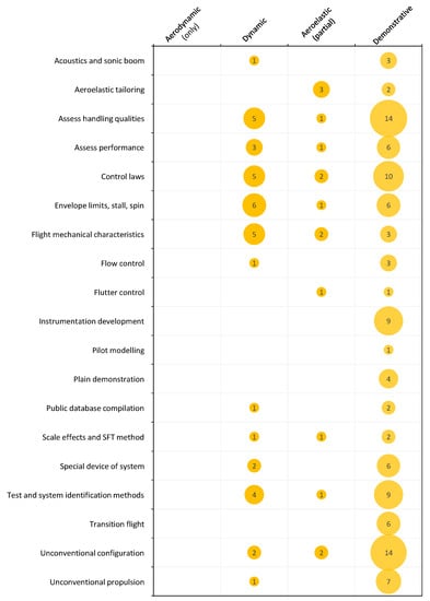
Figure 1.
Main research topics that the SFT platforms in Table 3 have been used for, along with their respective scaling methods. Note that each platform may have been used for multiple purposes.
2.4. Most Common Issues Associated with SFT
Both the literature review and the authors’ own experience from multiple SFT projects (see [7,91,92,93,94,95,127]) served to identify some of the most significant issues that affect typical SFT activities. These can be broadly summarised as follows:
- Scaling issues:
- −
- Not possible to attain sufficiently high Reynolds and Mach numbers to ensure aerodynamic similarity.
- −
- Flow distortion due to the need for model actuation, instrumentation, propulsion, and manufacturing constraints.
- −
- Not possible to attain dynamic similarity with Froude and Mach numbers simultaneously.
- −
- Similarity in mass ratio and inertia is severely constrained by operational, economic and practical limitations.
- −
- Dissimilar mass and inertia variations during flight due to different fuel fractions and fuel system.
- −
- Quick angular motion at small scales impose hard requirements on actuation and data acquisition systems.
- −
- Not possible to match aeroelastic similarity criteria with dynamic similarity at practical model scales and speeds.
- −
- Difficult to attain similarity in stiffness, mass distribution and inertial characteristics in a functional aeroelastic model.
- Flight testing issues:
- −
- Severe airspace and operational constraints for remotely piloted aircraft.
- −
- Optimum flight test organisation and procedures differ from those typical of full scale testing.
- −
- Lack of appropriate instrumentation and data acquisition systems for small vehicles.
- Data analytics issues:
- −
- Measurements usually disturbed by turbulence due to ground proximity and operational constraints.
- −
- Lack of an appropriate specialised framework for data conditioning and visualisation.
3. Tackling SFT Issues
Different approaches and solutions to the SFT issues identified in Section 2.4 are discussed here. The authors’ proposals will be presented along with other relevant approaches found in the literature.
3.1. Approaches to Scaling Issues
Except for demonstrative platforms with no strict similarity requirements, the fundamental limitations mentioned in Section 2.4 affect all scaling methods. Four aircraft concepts, with subscale models manufactured and flown at Linköping University, will be used here to illustrate and discuss some of these limitations. The design characteristics of these full-scale concepts are presented in Table 4.
Table 4.
Full-scale characteristics of four aircraft concepts used to illustrate the scaling limitations and possibilities. Linköping University has manufactured and flown a subscale model of each concept. * The mass in parenthesis indicates the mass that the scaled GFF should fly at to fulfil dynamic similarity.
3.1.1. Management of Flow Differences
The first scaling issue refers to the difficulty of achieving sufficiently high Reynolds and Mach numbers to ensure similar flow behaviour at both full-scale and subscale. Both quantities are strongly influenced by the flow properties. Adjusting the air conditions at will, as done in pressurised or cryogenic wind tunnels, is not an option when free-flying in the open atmosphere. In most cases, the impact of these two parameters can be studied independently, considering that Reynolds number effects are typically negligible outside the boundary-layer region near the body surface [5,128,129,130]. Experimental studies such as [131,132] support this assumption by showing a clear distinction between the effect of Mach number and effects caused by Reynolds number variations. This assumption is valid for subsonic and supersonic flow for Mach numbers less than approximately 5, a point at which the shock waves start interacting extensively with the boundary layer, and hence Mach number effects couple to viscous effects [1].
Focusing first on the Reynolds number deviations, this problem is closely coupled to the scale factor of the model since Reynolds number is directly proportional to a characteristic linear dimension, l in Equation (3)(a). Although it could be compensated for by a higher flight speed and air density, these are usually limited by practical testing constraints. Independently of the type of aircraft, a deviation in Reynolds number is therefore unavoidable at small scales, as demonstrated by the different tests shown in Figure 2.
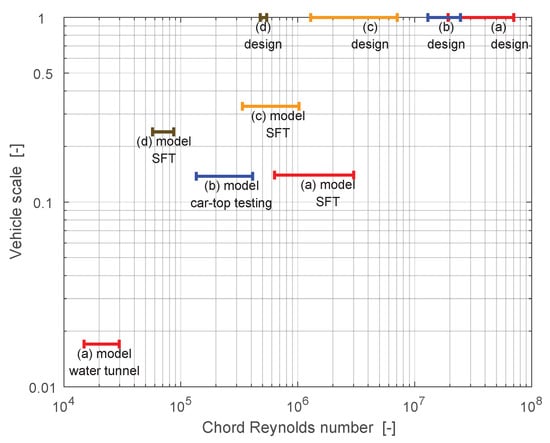
Figure 2.
Wing mean-chord Reynolds number achieved by different subscale models (’model’) and testing techniques at sea level, compared to the nominal design values (’design’) of the respective full-scale concepts of Table 4.
While there is no simple solution to this issue, the most obvious mitigation strategy is minimising these deviations by aiming for larger scale factors and focusing on the modelling of relatively small and slow aircraft such as general aviation aircraft. This is exemplified by the Light-Sport Aircraft concept (c) in Figure 2, where the 34%-scale, jet-powered model also flies at speeds comparable to those of the full-scale counterpart.
A second alternative, appropriate for a wider range of applications, is to geometrically modify the subscale model to mitigate low-Reynolds-number effects on the flow and the flying characteristics. This approach requires a detailed estimation or measurement of both the full-scale and subscale characteristics in order to identify the sensitivities and design appropriate modifications. For instance, a common technique to simulate flow conditions expected at a higher Reynolds number is to artificially fix the laminar-turbulent transition and the separation at a predefined location by means of grit, strips and other flow-tripping devices [1,128]. Examples of more substantial geometrical modifications applied to SFT platforms can be found in the literature: Heine et al. [133] and Vahora et al. [134] show re-designs of the main wing aerofoil to match the full-scale performance, a technique also implemented on the e-Genius-Mod (Bergmann et al. [22]) and the GA-USTAR (Ananda et al. [36]) SFT platforms. This approach is also discussed by Raju-Kulkarni et al. in [135], where it is also proposed to use specifically designed, aerodynamically tailored, subscale models for individual experiments limited to certain flight characteristics of interest.
A third approach to this issue is to rely on knowledge of the flow characteristics and take advantage of the Reynolds number insensitivity of certain flow phenomena, i.e., to accept any deviations while being aware of their general effects. Because of their effects on the boundary layer, Reynolds number variations have a strong impact on the flow topology and forces produced across bodies for which there is no geometrically fixed separation, such as smooth and curved surfaces [128,130]. In flow around sharp corners, however, the separation is usually fixed at the edge and the flow often presents little or no dependence on Reynolds number. This kind of sharp feature is commonly found in modern combat aircraft with a large flight envelope and stealth capabilities. For instance, many contemporary fighters feature chined forebodies and highly swept lifting surfaces for controlled radar reflectivity, high-speed performance and high angle-of-attack (AOA) excursions. This approach is used by the authors in the case of the GFF concept (a), where the aerodynamics at high AOA are dominated by separated flow and vortex structures. Although the boundary layer region prior to separation is strongly dependent on Reynolds number, both the vortex sheet and the inviscid outer flow region remain relatively insensitive to Reynolds number variations [130]. Furthermore, the literature generally agrees that the separation location, trajectory and breakdown of the primary vortices is mainly determined by the geometry and the angles of attack and sideslip in sharp and highly swept surfaces. Consequently, configurations with these characteristics are especially well suited for experiments with subscale models in which Reynolds number similarity cannot be maintained.
With respect to the second part of the aerodynamic similarity issue, deviations in Mach number are more difficult to avoid and mitigate. The literature agrees that the Mach number has a significant influence on the flow characteristics as soon as compressibility effects begin to be significant, and this may happen even far below the transonic regime. Wolowicz et al. [1] state that the differences in true and incompressible-flow dynamic pressure and temperature may be significant for Mach numbers in excess of 0.20, while other sources often extend this limit to Mach 0.3. It should be noted that even in a flow with a low free-stream Mach number, compressibility effects may be significant in local flow around certain geometries. For instance, the studies on the F/A-18 fighter configuration reviewed by Erickson et al. [136] revealed that the flow around some components such as leading-edge extensions present compressibility effects at Mach numbers as low as 0.15–0.25.
In contrast to the Reynolds number, the Mach number is not directly related to the scale factor of the model but a consequence of the structural design of the model, its propulsion system, and the maximum flight speed at which the model can be safely controlled. There are no effective techniques to artificially compensate for Mach number dissimilarity, which makes it an important limitation for all studies in which compressible flow is relevant. Figure 3 illustrates this issue by showing the different regimes at which the concepts of Table 4 were tested. Unless the subscale models are specifically prepared and allowed to fly at very high speeds (as in the case of some drop-models used by NASA [2,137]), SFT experiments are necessarily constrained to the study of the low subsonic regime.
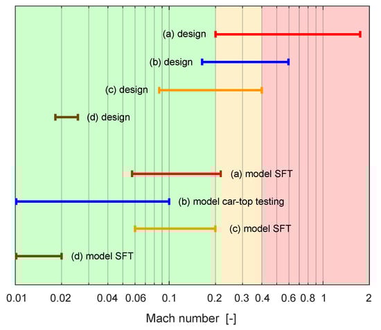
Figure 3.
Mach number at which the subscale models of Table 4 are tested in the open atmosphere, compared to the Mach number range where the full-scale vehicles would be operated. The background colours represent incompressible (green), risk of compressibility (yellow) and compressible (red) flow regimes.
In addition to the issues caused by dissimilarity, local flow disturbances can also be introduced by instrumentation, mechanisms, propulsion or any other systems needed for a functional free-flying model. In most cases, these are considerably different to those of the full-scale concept, and can cause unintended effects in the flow topology and flight performance. Thanks to the miniaturisation of mechatronics and radio-control (RC) systems, a relatively unobtrusive system integration is often possible even at small scales (see for instance [45,127,138,139]), but some modifications may remain unavoidable. In those cases, a complementary computational fluid dynamics (CFD) or wind-tunnel study may help isolate the effects.
Even with unavoidable differences in flow characteristics with respect to the full-scale aircraft, SFT can always be used to validate the aerodynamic characteristics of a corresponding virtual subscale simulation model. The aerodynamic scaling effects between full-scale and subscale simulation models, denominated ’virtual scaling error’ in [135], can then be studied with other methods such as CFD, as commonly done in contemporary wind tunnel experiments [140].
3.1.2. Management of Dynamic Similarity, Mass, and Response Time
The Froude number, parameter (m) in Equation (3), becomes significant whenever dynamic similarity is considered. This parameter, however, dictates different requirements for subscale model velocity than those coming from the Reynolds and Mach numbers. Even assuming a certain degree of Reynolds number dissimilarity, satisfying both Mach and Froude numbers simultaneously would require an improbable change in the gravitational field. This issue generates two possible approaches to dynamic scaling: one that pursues complete Froude number similarity at the expense of dissimilar fluid-compressibility effects, and another that pursues complete Mach number similarity at the expense of dissimilar proportions between inertial and gravitational effects. The first is commonly known as Froude scaling, while the latter is sometimes referred to as Mach scaling [1]. Froude number similarity can be met by tailoring the mass properties of the subscale model, which is significantly easier to achieve than Mach number similarity, as discussed above. In fact, all the SFT platforms listed in Table 3 that use dynamic scaling are based on the Froude scaling variant. This is also the approach followed by the authors in all dynamically scaled platforms at Linköping University.
Further, the similarity of mass ratio and mass moments of inertia, terms (d) and (e) in Equation (3), prescribe model weights that can differ significantly from those found in similar non-dynamically scaled models. If the aircraft is assumed to be a rigid body, the moments and products of inertia can easily be matched by distributing individual masses along the airframe, although this technique is only applicable if the airframe is initially lighter than the target weight. In fact, achieving the right inertial characteristics becomes rather challenging if the prescribed weight is lower than that resulting from a typical model manufacturing process: special materials or manufacturing techniques may be necessary and the inertia requirements may have a significant impact on the model design. This was the case for the subscale model of a human powered aircraft (case (d) in Table 4), where the weight budget for a 6-metre wing was under 200 g.
In some cases, the requirements for similarity in mass and inertial characteristics will make it impractical or infeasible to conduct a subscale experiment at certain scale factors. The different examples introduced in Table 4, plus two additional cases, are used in Figure 4 to illustrate this problem. Here, the background colours suggest a relative level of difficulty (and eventual cost) of performing SFT with instrumented, dynamically scaled models according to their take-off mass: low (green), medium (yellow) and high (red). For instance, the legal requirements for civil operation of this kind of vehicle in many European countries change significantly when the take-off mass exceeds 25 kg, and even more dramatically when it exceeds 150 kg. On the lower side, it becomes generally difficult to build and operate a functional model of less than 1 kg of take-off mass including the necessary instrumentation. Figure 4 shows two lines for each case: the solid lines represent similarity to the full-scale vehicle at sea level, while the dashed lines represent similarity to the full-scale vehicle when it flies at its design altitude. The GFF, indicated as (a), is a good example of the trade-off needed: the subscale model is operated below the required weight for dynamic similarity in order to avoid the cost and the legal requirements of a heavier vehicle category.
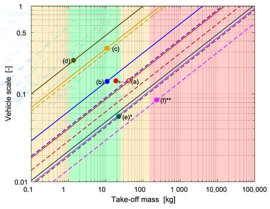
Figure 4.
Take-off mass and scale factor according to dynamic similarity for SFT at sea level. Background colours indicate relative complexity, considering the challenges and cost of manufacturing and operation. Solid lines represent similarity to the full-scale vehicle at sea level while dashed lines represent similarity to the full-scale vehicle at its design altitude. The GFF subscale model in case (a) is lighter than prescribed due to cost and regulations. Besides the aircraft described in Table 4, two complementary examples have been added: * (e) corresponds to NASA’s AirSTAR GTM-T2 [121], and ** (f) corresponds to NASA-Boeing’s X-48B [108], both scaled with respect to their design altitude.
Another potential problem relating to dynamically scaled experiments is the decrease of actuation and response times with the scale factor, at a rate of . The model may not only require higher sampling rates from the instrumentation and data acquisition systems, but also demand a faster control system: the speed at which the control surfaces are deflected should match the time requirements. While the latency of the radio-control system is usually not a problem with modern equipment, a bottleneck can be found at the speed of proportional servo-actuators. Commercial off-the-shelf (COTS) digital servo-actuators were sufficient for the subscale models presented in Table 4. However, smaller scales may require special high-speed servo-actuators or even alternative solutions such as simpler, non-proportional (on-off) high-speed actuators with separate pilots for each axis, as used by NASA in various small-scale models in the past [1,2,137].
3.1.3. Aeroelastic Considerations
For a general dynamic problem with a flexible aircraft, obtaining similar aerodynamic forces and moments would require satisfying all the similarity parameters in Equation (3). This general formulation includes the elastic similarity between full-scale and subscale vehicles by means of the parameters (f) and (g), which account for the aeroelastic bending and aeroelastic torsion, respectively. While in dynamically scaled rigid aircraft, similarity in mass moments and products of inertia could be met by adding the necessary masses on the airframe, aeroelastic scaling requires that the actual distribution of these masses is similar to that of the full-scale vehicle [1]. This detail adds a significant complexity to the design and manufacturing of the model, considering that the loads do not scale at the same rate as the stiffness and that the structural construction of models is normally different [137].
Two different approaches to this issue are found in the literature. The first approach consists on focusing of specific aeroelastic problems and proposing a specific similarity formulation for each case. By assuming a partial similarity, tailored to the specific problem of interest, it is possible to find a balance between a feasible platform and a flight-test solution. For instance, Ouellette et al. propose in [66] a more practical set of aeroelastic scaling laws applied to the study of couplings between the short-period mode and the wing structural dynamics such as body freedom flutter (BFF) [141]. Among other simplifications, these authors argue that the sensitivity of the short-period mode to the Froude number is generally low and therefore the flight velocity can be lower than that prescribed by typical Froude scaling. The reduced set of similarity requirements allowed the development of a feasible subscale experiment whose results were reported in [67]. Another example of this approach for the study of BFF is the Lockheed Martin X-56A or Multi-Utility Technology Testbed (MUTT), a 15% scaled version of the Sensorcraft configuration with interchangeable wings [77,78,142].
The second alternative is to further disregard other similarity factors and focus exclusively on investigating the aeroelastic problem of interest. In practice, this approach blends with the demonstrative scaling method as defined in Section 2.2. An early example of this approach is the Drones for Aerodynamic and Structural Testing (DAST) programme carried out by NASA from 1977 to 1983 [143,144,145]. During this programme, two BQM-34 Firebee II target drones were modified with supercritical aerofoils and new wing geometry, the Aeroelastic Research Wing (ARW). These vehicles were mainly used to evaluate active control systems and flutter suppression techniques, as well as for stability and structural investigations. A more recent take on active flutter control and aeroelastic tailoring is the European Flutter-free Flight Envelope Extension for Economical Performance Improvement (FLEXOP) research project [13,14,15,16,17,18] and its continuation, FLiPASED.
3.1.4. The Demonstrative Scaling Approach
Demonstrative SFT platforms, as defined previously, are not necessarily bound by the typical similarity parameters in Equation (3). The scaling principle is applied to the technology or capability, and not necessarily to the entire vehicle. Therefore, it is not possible to generalise how scaling issues affect these experiments. They are, however, exposed to the same issues regarding flight testing and data analytics.
3.2. Approaches to Flight-Testing Issues
There are multiple approaches to flight testing subscale aircraft. Critical aspects for flight test design, such as risk evaluation and infrastructure requirements, vary widely between different test objects. Additionally, the existing regulations for unmanned aircraft systems (UAS) in most countries define a significant step in requirements between flight within visual line-of-sight (VLOS) and beyond visual line-of-sight (BVLOS) [146]. Low-cost equipment for extended-VLOS (EVLOS) and BVLOS operations is readily available, but a civil operator is usually asked to either certify the system according to nearly full-scale standards or operate inside costly segregated airspaces [147,148,149]. In practice, certification is usually not feasible and only a few civil organisations can make regular use of segregated airspaces to fly BVLOS operations. Instead, most organizations perform SFT in non-segregated airspace following EVLOS and VLOS rules as far as practical. While an exact classification cannot be formulated, most of the SFT experiments found in literature could be roughly divided into four different categories according to the type of operation and standards, see Table 5.
Table 5.
Rough classification of different approaches to SFT according to operation and safety levels.
There is extensive literature covering flight-testing methods for both for conventional [150,151] and relatively large unmanned vehicles [152,153,154], which could be related to SFT experiments of level 4 and some of level 3 in Table 5. Despite being more common, little has been published about specific methods for VLOS testing of relatively smaller RPA, i.e., experiments corresponding to levels 1 and 2, and even some at level 3. A good example of the testing conditions within VLOS is the FLEXOP project, where the limited airspace and the relatively large size of the demonstrator had an important impact on the design of the experiment and the vehicle itself [13,14]. The procedure description given by Bunge et al. [40] illustrates a typical test of much smaller aircraft at level 1. Most subscale platforms at Linköping University are tested at levels 1 and 2. Among these, the GFF demonstrator (case (a) in Table 4) represents the most challenging case for SFT within VLOS at level 2. This case will therefore be used here as an example to present the authors’ solutions. Figure 5 represents typical conditions found when flight testing this type of platform within VLOS, although the exact available range and height might vary slightly depending on the local regulations and safety margins.
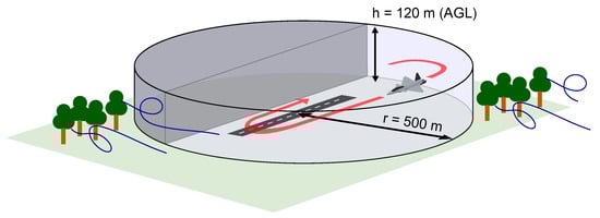
Figure 5.
Typical airspace available for flight testing within VLOS (levels 1 and 2 in Table 5): a challenging environment with severe exposure to ground turbulence.
3.2.1. Optimising SFT at Levels 1 and 2
In a previous publication, the authors proposed and tested three techniques to cope with some of the issues that hinder high-quality data acquisition during VLOS testing (levels 1 and 2 in in Table 5): short testing time, imprecision of excitation manoeuvres, constant manoeuvring and lack of steady conditions [93]:
- Automation of test manoeuvres: Custom-made software that is able to precisely command any kind of pre-programmed excitation manoeuvres without the need for a closed-loop flight controller or an on-line ground station, hence avoiding eventual redundancy and certification requirements.
- Optimised manoeuvres for flight mechanical characteristics: Reduce exposure time by exciting different axes and controls simultaneously using multisine signals [94].
- Optimised manoeuvres for performance evaluation: Executing certain dynamic manoeuvres that allow for the exploration of a wide area of the polar in a short time. Figure 6 is an example of the lift characteristics of the GFF demonstrator identified from a single flight using some of the manoeuvres proposed in [93].
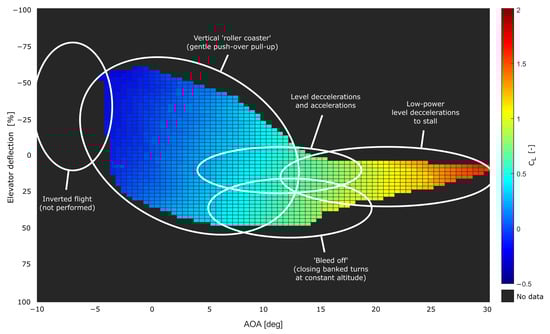 Figure 6. An example of SFT at level 2 for performance evaluation: lift characteristics of the GFF demonstrator identified from a single flight using short dynamic manoeuvres within VLOS.
For most SFT campaigns with relatively small vehicles and limited to VLOS, imitating the flight test organisation and execution procedures normally used in conventional flight testing of large RPA or manned vehicles (level 4 and above) is far from optimal. Failing to recognise the specific needs and the inherent advantages of SFT within VLOS, especially in the case of relatively small vehicles at levels 1 and 2, defeats the purpose of scaled testing by eventually increasing costs, time, and administrative burden. Figure 7 tries to illustrate this idea by comparing the relative importance typically given to different factors on both manned/level 4 SFT and levels 1 and 2 SFT.
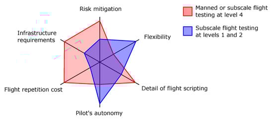
Figure 7.
Conceptual representation of some of the differences between planning manned flight testing and subscale flight testing with relatively small models.
A good example of the need for a reasonable approach is the level to which the flight is planned and scripted in test cards. Figure 8 illustrates the approach followed during flight testing of the GFF demonstrator at level 2. Each circuit is divided into a test manoeuvre and a pattern flight. The test manoeuvre takes place inside a defined test window, while the pattern flight makes use of the available manoeuvring area inside the safety limits. Instead of defining each consecutive movement of the aircraft during the circuit, the test cards focus on specifying the conditions at which the aircraft should enter the test window and the precise movements that should be done inside it. In most cases, the test manoeuvre can also be executed automatically using the application described in [93]. The pattern flight is then executed in a relatively free manner, but always within previously agreed parameters and speeds.
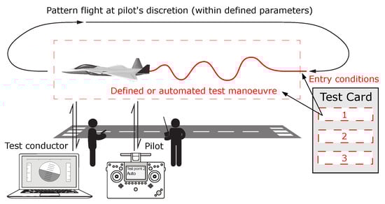
Figure 8.
A more practical approach to SFT planning at levels 1 and 2: only entry conditions and manoeuvres inside the test window are scripted in detail.
This approach gives more flexibility to the remote pilot, but also relies heavily on his or her judgment during the flight. The results obtained after several campaigns with the GFF demonstrator suggest that this procedure is beneficial even at level 2. Considering the reduced airspace, the influence of external factors and the speed at which the events usually unfold, the remote pilot is often in the best position to judge the optimal manoeuvring needed to attain the desired entry conditions before the next manoeuvre. A real-life example of the application of this method in level 2 SFT of the GFF demonstrator is shown in Figure 9, which corresponds to the same flight that generated the data shown in Figure 6.
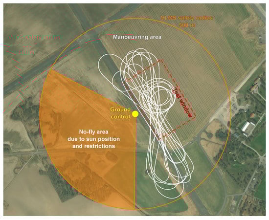
Figure 9.
Example of SFT at level 2 using the concept of test-window and flexible pattern. This specific flight of the GFF demonstrator corresponds to the manoeuvres and performance data shown in Figure 6.
3.2.2. Specific Data Acquisition Solutions
The instruments and data acquisition systems typically used in manned flight testing are, in most cases, not appropriate for subscale aircraft. The main reasons are often weight, size and relative cost, but can also include different needs in terms of resolution and sampling frequency. For example, while an altitude error of 5 m and a sampling frequency of 25 Hz may be acceptable for flight testing the performance of a full-scale aircraft, it can be insufficient for a subscale aircraft with faster dynamics and operating between 0 and 120 m above the ground.
Researchers have approached this issue with a variety of solutions, including both standalone data acquisition systems and integrated flight control systems (autopilots) with data logging capabilities. Dantsker et al. [45] present an extensive review of different solutions used for research purposes by different organisations. Until recently, COTS solutions for data acquisition were limited to few hobbyist-type systems such as the Eagle Tree Systems Flight Data Recorder [155] or higher-end, industrial UAV systems such as the RCATS UAV [156]. COTS autopilot systems for UAV, such as the Cloud Cap Piccolo series [157], have also been used for data logging in several projects. The gap between these two levels was filled with a variety of custom-made data acquisition solutions, most of which were based on the integration of custom and COTS sensors of different types but resulting in similar architectures [44,56,69,95,138,139,158,159]. The need for an intermediate-level system, specifically adapted to the SFT needs, has motivated the recent appearance of a few specialised COTS solutions such as the Al Volo FDAQ [45].
Over the last few years, in line with the expansion of the consumer and semi-professional UAV market, many open-source autopilot software projects have reached the community. In some cases, these projects also commercialise accompanying hardware with different capabilities and at different levels of integration. Paparazzi [160] and PX4/Pixhawk [161] are two well-known projects that are commonly used in research applications [12,20,40,127,162,163]. Open UAV-software development platforms such as DRONEKIT [164] and the Dronecode Foundation [165] also provide tools that facilitate a quick integration of data acquisition components and functions. The current availability of capable low-cost sensors and miniaturised processing boards, in combination with these software tools, enable the development of custom data acquisition solutions at very low costs, such as the system presented by Koeberle et al. [159].
The data acquisition system currently used in SFT experiments at Linköping University is also a good example of a low-cost, custom implementation based on a commercially available, open-source autopilot from the UAV segment. This data acquisition system integrates both COTS and custom-made instruments, while the flight controls are operated separately using a professional COTS RC system. The data system is built around a Pixhawk flight controller [161] running a modified version of the Ardupilot open-source software [166] for dedicated and enhanced logging capabilities. This controller is complemented by both COTS and custom-made transducers and communication modules. Figure 10 shows a general layout of the system components integrated into the GFF demonstrator. While telemetry is only used to monitor critical flight parameters during flight, both raw and fused sensor data are logged on board at sampling rates up to 100 Hz.
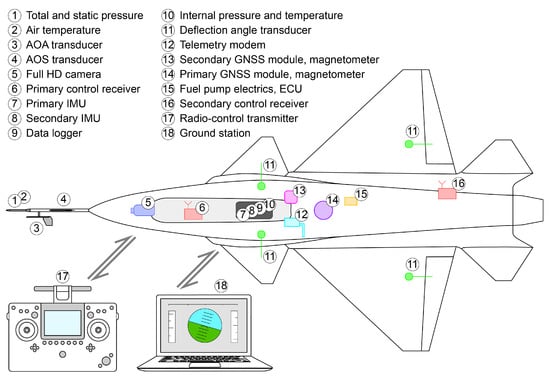
Figure 10.
Example of a low-cost, customised data acquisition system based initially on a commercially available open-source autopilot: Layout of the main components and radio links currently implemented on the GFF demonstrator.
Some generic data acquisition system components (imaging, positioning, communication devices) are usually best sourced from the general electronics and UAV markets. However, more specialised flight-test instruments may still require customisation or vehicle-specific development. Airdata probes and flow-angle transducers in small subscale aircraft are a good example of this issue. The smallest five-hole probe solution commercialised by Aeroprobe Corporation [167,168] is widely used for low-AOA tests provided that there is enough volume to allocate the hardware; however, few vane-based solutions exist at such small scales. Figure 11 shows two custom-made airdata systems developed for two different SFT applications: a high-speed, full-data model used on the GFF demonstrator, and a simpler, lightweight model used on a smaller test-bed aircraft.
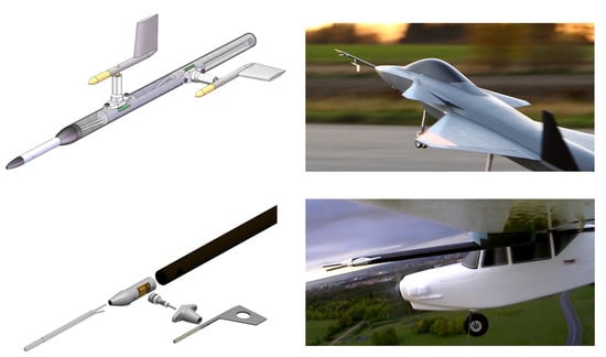
Figure 11.
Two airdata probes with contactless flow-angle transducers custom-made for two different applications: A rugged, full pitot-alpha-beta system for high-speed flight using the GFF demonstrator (top), and a low-weight, pitot-alpha system with 3D-printed parts developed for a low-speed test-bed aircraft (bottom).
3.3. Approaches to Data Analytics Issues
Even with efficient use of manoeuvring time and airspace, measurements from SFT at very low altitude may still suffer from significant contamination from air turbulence. In contrast to other more defined or coloured measurement noise sources, such as propulsion-system vibrations or actuators, turbulence can mix with the dynamic frequencies of interest and it can be challenging to filter out its effects. Besides flying in favourable weather conditions, the only possible mitigation lies in the data analysis method. In [169], Morelli et al. proposed a robust method for the identification of flight mechanical characteristics in turbulent environments and demonstrated it using NASA’s GTM T-2 subscale aircraft. This method is based on system identification in the frequency domain and indicated for the evaluation of flight-mechanical characteristics. Other studies such as [170] also followed a similar approach to develop an suitable identification method and confirmed that the influence of wind gusts and turbulence is more significant than that of sensor noise. In [94], the GFF demonstrator was used to develop and verify an enhanced identification method to cope with high levels of turbulence in the flight-test measurements.
Filtering signals, conditioning data, checking for consistency and estimating results are usual tasks performed in all sorts of flight testing, not only SFT. Organisations with flight-testing capabilities have usually developed proprietary tools to cover these tasks both online (in real time) and offline, but in most cases these are focused on full-scale vehicles and manned flight-testing operations. Software tools covering certain parts of the offline data analysis process have been released to the community for research (see NASA’s SIDPAC for system identification [171]) and educational (see the collection of programmes offered in [172]) purposes. Further, NASA’s open-source Open Mission Control Technologies (OpenMCT) visualisation framework is being increasingly used in SFT projects to manage, display and broadcast real-time telemetry data. Both commercial and open-source UAV ground-control software such as Mission Planner [173] also begin to offer some degree of data analysis capabilities. While most of these tools are perfectly applicable to SFT experiments, there is currently no freely available, integrated flight-test data analysis solution that is specifically tailored to SFT needs.
In addition to a usually large mix of sensors of different types, SFT experiments sometimes involve quick changes of configuration or relatively frequent changes in the data acquisition system. The Aircraft Log Analysis (ALAN) software is a collection of tools for MathWorks, Inc. (Natick, MA, USA) MATLAB environment (versions 9.2 and higher) that has been developed at Linköping University with these needs in mind. ALAN, currently in its second version and soon to be released as open code, covers a large portion of the usual post-flight analysis tasks. Figure 12 describes the workflow and the kinds of tasks that can be performed in this software.
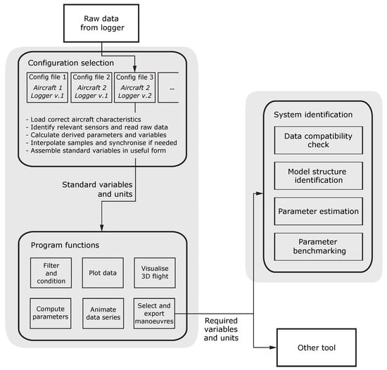
Figure 12.
Simplified workflow describing post-flight data analysis using the ALAN software (v2.0, Linköping University, Linköping, Sweden), which currently covers the shaded areas.
Particular importance has been attached to the data visualisation capabilities of the software. On the one hand, a comprehensive presentation of the flight data not only enables a better comprehension of the events but also allows a much quicker identification of segments of interest. In addition to typical plotting functions, this was achieved by presenting data in different forms of animation, including a virtual 3D reproduction of the vehicle during flight (Figure 13). On the other hand, an intuitive and visual display of generated results facilitates quicker evaluation and verification. Figure 14 presents an example where a set of manoeuvres is manually selected for parameter estimation by directly clicking over the plot area. The results obtained are then presented graphically, allowing a quick comparison between the different time-domain methods used.
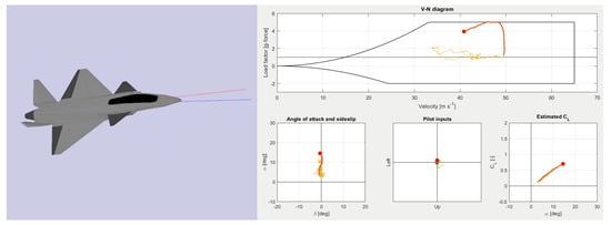
Figure 13.
Post-flight, animated data visualisation in ALAN software showing a manoeuvre of the GFF demonstrator.
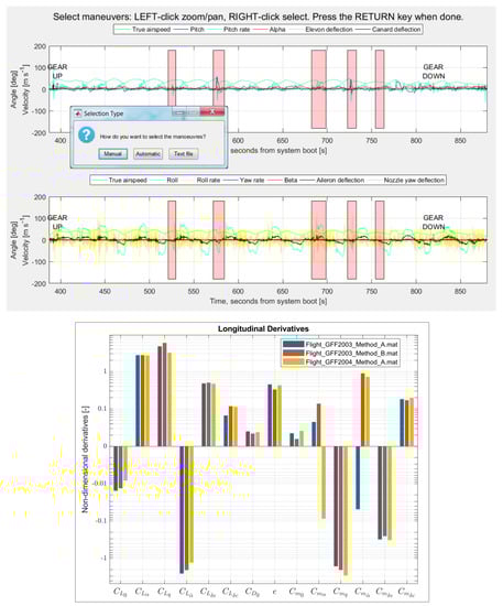
Figure 14.
Manual selection of a set of test manoeuvres (top) and graphical comparison of parameter estimation results for different sets and methods (bottom).
4. The Role of SFT in Aircraft Development and Opportunities for Future Research
Aerodynamic, dynamic or aeroelastic scaling can be effectively used to complement and validate digital design tools and simulations models. However, as computing resources increase and estimation methods based on CFD become more sophisticated, interest in using SFT as a tool for estimating or verifying flight characteristics seems to be waning. Research activity during the last decade indicates that the main interest in SFT is shifting from a flight-characteristics estimator to broader use as a low-cost technology-testing platform. The use of demonstrative scaling—partially or entirely disregarding the physical similarity of the vehicle with the purpose of evaluating a representative version of its technology—is becoming increasingly predominant. This approach seems especially appropriate for the early development stages, when the vehicle configuration is not yet well defined and accurate scaling is thus irrelevant.
In contrast to CFD simulations and wind-tunnel testing, the SFT method is not particularly well suited for the precise estimation tasks and minor design refinements typically carried out during the detailed design stages of aircraft development. SFT can instead play a much more valuable role during a pre-conceptual or conceptual-design phase. Figure 15 illustrates this idea by showing a possible application of SFT during the initial stages of a typical aircraft development process. In this figure, the areas highlighted indicate where SFT experiments can provide unique information or complement other design tools.
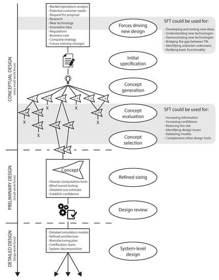
Figure 15.
An interpretation of the initial stages of a contemporary aircraft development process, where the shaded areas indicate the potential application of SFT.
Nevertheless, some of the SFT method’s previously discussed issues remain partially unresolved. Other aspects or potential applications of SFT are currently insufficiently explored, or lack a contemporary analysis. According to the knowledge gaps identified in this study, the following topics could be of great interest for future research:
- Implications of partial similarity and scaling inaccuracies on the measurability, fidelity and extrapolability of flight characteristics: Beyond basic aerodynamic considerations such as Reynolds number or compressibility deviations, the effects of not fulfilling other similarity parameters is still a controversial topic, especially if the purpose of the SFT experiment is to estimate the flight or handling characteristics of a full-scale vehicle. While this topic has been widely discussed in the wind-tunnel literature, little open information is available for free-flight models. Recent publications [8,135,174] show ongoing efforts to identify and quantify these effects using different approaches.
- Benefits of early subscale experimentation in the maturation of new technology using a demonstrative scaling approach: While the growing interest in using demonstrative subscale platforms to increase the technology readiness level (TRL) of new technologies may indicate that the method has a positive effect in the development process, no scientific studies have tried to interpret or quantify these benefits in comparison to other development strategies.
- Suitability of SFT for the evaluation of handling qualities with a human pilot in the loop: The usefulness of SFT for experimenting with automatic flight control laws is, at this point, indisputable. However, its suitability for obtaining human-pilot ratings of handling qualities is unclear. Earlier experiences from NASA [2] suggest that SFT may not be appropriate for this purpose while Mandal et al. [70] suggest wide variations in pilot behaviour. Specific studies taking into account modern control and information augmentation systems would be desirable.
- Specific flight-testing methods, measurement and analysis techniques for efficient subscale experiments: The testing environment, procedures and even the measurement solutions often seem to play an important role in both the capabilities and the results of SFT. While this is a wide area ranging from unmanned aircraft operations to manoeuvre design and data acquisition techniques, its understanding is key to enabling efficient and useful SFT experiments.
5. Conclusions
There seems to be growing interest in using subscale flight testing as a research and development tool. Compared to traditional subscale flight testing platforms, recent advances in mechatronics, rapid prototyping and unmanned-vehicle technologies now seem to favour the use of smaller vehicles and low-cost systems.
The practical use of subscale flight testing for the replication of full-scale flight behaviour is clearly limited by unavoidable physical constraints derived from the similarity principles. Only a limited number of flow conditions can be explored with free-flight subscale models at low altitude without accounting for undesired scale effects. This, added to the convenience of computational methods, may explain why subscale flight testing is currently unpopular for studying purely aerodynamic problems. However, the use of subscale flight testing to study both rigid- and flexible-body flight dynamics is more common and constitutes an alternative to certain kind of costly or unfeasible wind-tunnel tests. In these cases, aerodynamic (flow) similarity is typically relaxed or reduced to the replication of the most characteristic parameters.
The review of current research also shows that the main use of subscale flight testing is progressively shifting from a flight-characteristics estimator to a broader use as a low-cost technology-testing platform. The use of subscale models to evaluate a scaled version of a new technology or feature, partially or entirely disregarding vehicle similarity, is becoming increasingly common. This practice is defined here as a demonstrative scaling approach.
Regarding flight testing methods, the subscale flight testing projects examined present large differences in equipment, facilities, procedures and, hence, costs. In most cases, the requirement to operate within visual line-of-sight appears to be the main factor constraining the potential and efficiency of the experiments. Specific flight-testing solutions for visual line-of-sight are evaluated and suggested.
The general lack of specialised testing instruments, avionics and analysis tools for subscale platforms is being progressively filled by industrial systems for unmanned aerial vehicles on one side, and by purpose-built systems mixing commercial off-the-shelf and custom-made solutions on the other. The recent proliferation of mass-produced and open-source components for the consumer ’drone’ segment has also facilitated the development of economical solutions. A low-cost data acquisition system with commercial off-the-shelf components and custom-made instruments is presented here as an example.
Considering the current capabilities as well as the volume and diversity of the findings obtained with subscale flight testing during the last years, it seems clear that this method can still play a valuable role during the early stages of aircraft design and low technology readiness levels. Further, its use can be expected to grow as the unmanned-systems market and other enabling technologies offer more capabilities at lower costs.
Author Contributions
Conceptualization and methodology, A.S., D.L. and P.K.; software, A.S.; hardware, A.S. and D.L.; experimentation, A.S. and D.L.; investigation, A.S.; writing—original draft preparation, A.S.; writing, review and editing, A.S., D.L. and P.K.; visualization, A.S.; supervision, D.L. and P.K.; project administration, P.K.; funding acquisition, P.K. All authors have read and agreed to the published version of the manuscript.
Funding
This research was funded by the Swedish Innovation Agency VINNOVA within project ’MESTA’, NFFP 2017-01502.
Conflicts of Interest
The authors declare no conflict of interest. The funders had no role in the design of the study; in the collection, analyses, or interpretation of data; in the writing of the manuscript, or in the decision to publish the results.
Abbreviations
The following nomenclature is used in this manuscript:
| AOA | Angle of attack |
| BVLOS | Beyond visual line-of-sight |
| CFD | Computational fluid dynamics |
| COTS | Commercial off-the-shelf |
| EVLOS | Extended visual line-of-sight |
| GFF | Generic Future Fighter |
| RC | Radio control |
| RPA | Remotely piloted aircraft |
| SFT | Subscale flight testing |
| TRL | Technology readiness level |
| UAV | Unmanned aerial vehicle |
| VLOS | Visual line-of-sight |
| Symbols | |
| a | Linear acceleration [m s] |
| Angle of attack [ or rad] | |
| Generalised aircraft attitude relative to airstream [ or rad] | |
| Angle of sideslip [ or rad] | |
| Lift coefficient [-] | |
| c | Speed of sound (in the pertinent fluid) [m s] |
| Control surface deflection angle [ or rad] | |
| E | Modulus of elasticity [Pa] |
| Bending stiffness [N m] | |
| F | Force [N] |
| Froude number [-] | |
| g | Acceleration due to gravity [m s] |
| Torsional stiffness [N m] | |
| I | Mass moment of inertia [kg m] |
| l | Characteristic linear dimension [m] |
| M | Mach number (context dependent) [-] |
| M | Moment (context dependent) [N m] |
| m | Mass [kg] |
| Dynamic (absolute) viscosity [Pa s] | |
| Kinematic viscosity [m s] | |
| Generalised angular rate [rad s] | |
| Frequency of oscillation [rad s] | |
| Generalised angular acceleration [rad s] | |
| Reynolds number [-] | |
| Mass density (of the pertinent fluid) [kg m] | |
| t | Time [s] |
| Time constant or reduced-time factor [-] | |
| V | Linear velocity [m s] |
References
- Wolowicz, C.H.; Bowman, J.S.; Gilbert, W.P. Similitude Requirements and Scaling Relationships as Applied to Model Testing; Technical Paper 1435; NASA: Washington, DC, USA, 1979.
- Chambers, J.R. Modeling Flight: The Role of Dynamically Scaled Free-Flight Models in Support of NASA’s Aerospace Programs, 1st ed.; NASA: Washington, DC, USA, 2009.
- Buckingham, E. On physically similar systems: Illustrations of the use of dimensional equations. Phys. Rev. 1914, 4, 345–376. [Google Scholar] [CrossRef]
- Kline, S.J. Similitude and Approximation Theory; McGraw-Hill: New York, NY, USA, 1965. [Google Scholar]
- Gainer, T.G.; Hoffman, S. Summary of Transformation Equations and Equations of Motion Used in Free-Flight and Wind-Tunnel Data Reduction and Analysis; Technical Report; NASA: Washington, DC, USA, 1972.
- Chambers, J.R. Cave of the Winds: The Remarkable History of the Langley Full-Scale Wind Tunnel; NASA: Washington, DC, USA, 2014.
- Lundström, D.; Amadori, K. Raven—A Subscale Radio Controlled Business Jet Demonstrator. In Proceedings of the 26th Congress of the International Council of the Aeronautical Sciences, Anchorage, AK, USA, 14–19 September 2008. [Google Scholar]
- Schmollgruber, P.; Lepage, A.; Bremmers, F.; Jentink, H.; Genito, N.; Rispoli, A.; Huhnd, M.; Meissner, D. Towards validation of scaled flight testing. In Proceedings of the 7th CEAS Air and Space Conference, First Aerospace Europe Conference, AEC2020, Bordeaux, France, 25–28 February 2020. [Google Scholar]
- Olejnik, A.; Kachel, S.; Rogólski, R.; Milczarczyk, J. The concept and methodical assumptions for the development of dynamically scaled aircraft model (passenger aircraft). MATEC Web Conf. 2019, 304. [Google Scholar] [CrossRef]
- Olejnik, A.; Kachel, S.; Rogólski, R.; Milczarczyk, J. Conception of developing the dynamically similar downscaled medium-range passenger airplane model for in-flight testing. Proc. Inst. Mech. Eng. Part G J. Aerosp. Eng. 2020. [Google Scholar] [CrossRef]
- Mieloszyk, J.; Tarnowski, A.; Tomaszewski, A.; Goetzendorf-Grabowski, T. Validation of flight dynamic stability optimization constraints with flight tests. Aerosp. Sci. Technol. 2020, 106, 106193. [Google Scholar] [CrossRef]
- Wilson, T.; Kirk, J.; Hobday, J.; Castrichini, A. Small scale flying demonstration of semi aeroelastic hinged wing tips. In Proceedings of the 18th International Forum on Aeroelasticity and Structural Dynamics, Savannah, GA, USA, 10–13 June 2019. [Google Scholar]
- Sendner, F.M.; Stahl, P.; Rößler, C.; Hornung, M. Designing an UAV Propulsion System for Dedicated Acceleration and Deceleration Requirements. In Proceedings of the 17th AIAA Aviation Technology, Integration, and Operations Conference, Denver, CO, USA, 5–9 June 2017. [Google Scholar] [CrossRef]
- Stahl, P.; Sendner, F.M.; Rößler, C.; Hornung, M.; Hermanutz, A. Mission and Aircraft Design of FLEXOP Unmanned Flying Demonstrator to Test Flutter Suppression within Visual Line of Sight. In Proceedings of the 17th AIAA Aviation Technology, Integration, and Operations Conference, Denver, CO, USA, 5–9 June 2017. [Google Scholar] [CrossRef]
- Roessler, C.; Stahl, P.; Sendner, F.; Hermanutz, A.; Koeberle, S.; Bartasevicius, J.; Rozov, V.; Breitsamter, C.; Hornung, M.; Meddaikar, Y.M.; et al. Aircraft Design and Testing of FLEXOP Unmanned Flying Demonstrator to Test Load Alleviation and Flutter Suppression of High Aspect Ratio Flexible Wings. In Proceedings of the AIAA SciTech 2019 Forum, San Diego, CA, USA, 7–11 January 2019. [Google Scholar] [CrossRef]
- Roessler, C.; Bartasevicius, J.; Koeberle, S.J.; Teubl, D.; Hornung, M.; Meddaikar, Y.M.; Dillinger, J.K.; Wustenhagen, M.; Kier, T.M.; Looye, G.; et al. Results of an Aeroelastically Tailored Wing on the FLEXOP Demonstrator Aircraft. In Proceedings of the AIAA SciTech 2020 Forum, Orlando, FL, USA, 6–10 January 2020. [Google Scholar] [CrossRef]
- Sodja, J.; Breuker, R.D.; Meddaikar, Y.M.; Dillinger, J.K.; Soal, K.; Govers, Y.; Krueger, W.; Georgopoulos, P.; Koimtzoglou, C.; Roessler, C.; et al. Ground Testing of the FLEXOP Demonstrator Aircraft. In Proceedings of the AIAA SciTech 2020 Forum, Orlando, FL, USA, 6–10 January 2020. [Google Scholar] [CrossRef]
- Takarics, B.; Patartics, B.; Luspay, T.; Vanek, B.; Roessler, C.; Bartasevicius, J.; Koeberle, S.J.; Hornung, M.; Teubl, D.; Pusch, M.; et al. Active Flutter Mitigation Testing on the FLEXOP Demonstrator Aircraft. In Proceedings of the AIAA SciTech 2020 Forum, Orlando, FL, USA, 6–10 January 2020. [Google Scholar] [CrossRef]
- Dantsker, O.D.; Vahora, M.; Mancuso, R. Flight and ground testing data set for subscale GA aircraft: 26. %-scale Cub Crafters CC11-100 Sport Cub S2. In Proceedings of the AIAA SciTech 2019 Forum, San Diego, CA, USA, 7–11 January 2019. [Google Scholar] [CrossRef]
- Courtin, C.; Hansman, R.J.; Drela, M. Flight Test Results of a Subscale Super-STOL Aircraft. In Proceedings of the AIAA SciTech 2020 Forum, Orlando, FL, USA, 6–10 January 2020. [Google Scholar] [CrossRef]
- Bergmann, D.P.; Denzel, J.; Strohmayer, A. UAS as flexible and innovative test platform for aircraft configuration and systems testing. In Proceedings of the EASN-CEAS 2018. MATEC Web of Conferences, Glasgow, UK, 4–7 September 2018; Volume 233. [Google Scholar] [CrossRef]
- Bergmann, D.P.; Denzel, J.; Baden, A.; Kugler, L.; Strohmayer, A. Innovative scaled test platform e-Genius-Mod-Scaling methods and systems design. Aerospace 2019, 6, 20. [Google Scholar] [CrossRef]
- Stolz, B.; Brodermann, T.; Castiello, E.; Englberger, G.; Erne, D.; Gasser, J.; Hayoz, E.; Muller, S.; Muhlebach, L.; Low, T.; et al. An Adaptive Landing Gear for Extending the Operational Range of Helicopters. In Proceedings of the 2018 IEEE/RSJ International Conference on Intelligent Robots and Systems (IROS), Madrid, Spain, 1–5 October 2018; Number 8594062. pp. 1757–1763. [Google Scholar] [CrossRef]
- Warren, M.M.; Kozel, F.K.; Li, E.Q.; Hall, C.S.; German, B.J. Design and control evaluation of a novel subscale quad-tiltrotor. In Proceedings of the AIAA SciTech 2019 Forum, San Diego, CA, USA, 7–11 January 2019. [Google Scholar] [CrossRef]
- Sanders, F.C.; Tischler, M.B.; Berger, T.; Berrios, M.G.; Gong, A. System identification and multi-objective longitudinal control law design for a small fixed-wing UAV. In Proceedings of the AIAA Atmospheric Flight Mechanics Conference, Kissimmee, FL, USA, 8–12 January 2018. [Google Scholar] [CrossRef]
- Pieper, K.; Perry, A.; Ansell, P.; Bretl, T. Design and Development of a Dynamically, Scaled Distributed Electric Propulsion Aircraft Testbed. In Proceedings of the 2018 AIAA/IEEE Electric Aircraft Technologies Symposium, Cincinnati, OH, USA, 9–11 July 2018. [Google Scholar] [CrossRef]
- Monteiro, D.d.M.; Nepomuceno, L.M.; da Silva, R.G.A.; da Silva e Souza, M.; Silvestre, F.J.; Krus, P.; Sobron, A. Subscale Flight Test Model Development and Testing as a Tool for Unconventional Aircraft Design. In Proceedings of the 6th CEAS Air and Space Conference, Aerospace Europe, Bucharest, Romania, 16–20 October 2017. [Google Scholar]
- Warsop, C.; Crowther, W. NATO AVT-239 Task Group: Flight Demonstration of Fluidic Flight Controls on the MAGMA Subscale Demonstrator Aircraft. In Proceedings of the AIAA SciTech 2019 Forum, San Diego, CA, USA, 7–11 January 2019. [Google Scholar] [CrossRef]
- Shearwood, T.R.; Nabawy, M.R.; Crowther, W.J.; Warsop, C. Directional Control of Finless Flying Wing Vehicles—An Assessment of Opportunities for Fluidic Actuation. In Proceedings of the AIAA Aviation 2019 Forum, Dallas, TX, USA, 17–21 June 2019. [Google Scholar] [CrossRef]
- Shearwood, T.R.; Nabawy, M.R.; Crowther, W.J.; Warsop, C. Yaw control of maneuvering tailless aircraft using induced drag—A control allocation method based on aerodynamic mode shapes. In Proceedings of the AIAA Aviation 2020 Forum, Virtual event, 15–19 June 2020; AIAA: Reston, VA, USA, 2020. [Google Scholar] [CrossRef]
- Brandt, S.S.; McLaughlin, T.E.; Williams, D.R.; Crawford, B.H.; Holmes, J.A. Nato avt-239 task group: Flight test of compressed and bleed-air driven control effectors on the ice/saccon uas subscale aircraft. In Proceedings of the AIAA SciTech 2019 Forum, San Diego, CA, USA, 7–11 January 2019. [Google Scholar] [CrossRef]
- Smith, G.; Bixler, B.; Babcock, J.T.; Osteroos, R.; McLaughlin, T.E.; Tischler, M.B. System Identification of the ICE/SACCON UAS Aircraft. In Proceedings of the AIAA SciTech 2020 Forum, Orlando, FL, USA, 6–10 January 2020. [Google Scholar] [CrossRef]
- Riddick, S.E.; Busan, R.C.; Cox, D.E.; Laughter, S.A. Learn to Fly Test Setup and Concept of Operations. In Proceedings of the 2018 Atmospheric Flight Mechanics Conference, Atlanta, GA, USA, 25–29 June 2018. [Google Scholar] [CrossRef]
- Heim, E.H.; Viken, E.; Brandon, J.M.; Croom, M.A. NASA’s Learn-to-Fly Project Overview. In Proceedings of the 2018 Atmospheric Flight Mechanics Conference, Atlanta, GA, USA, 25–29 June 2018. [Google Scholar] [CrossRef]
- Morelli, E.A. Practical aspects of real-time modeling for the learn-to-fly concept. In Proceedings of the 2018 Atmospheric Flight Mechanics Conference, Atlanta, GA, USA, 25–29 June 2018. [Google Scholar] [CrossRef]
- Ananda, G.K.; Vahora, M.; Dantsker, O.D.; Selig, M.S. Design methodology and flight test protocols for a dynamically-scaled general aviation aircraft. In Proceedings of the 35th AIAA Applied Aerodynamics Conference, Denver, CO, USA, 5–9 June 2017. [Google Scholar]
- Dantsker, O.D.; Ananda, G.K.; Selig, M.S. GA-USTAR phase 1: Development and flight testing of the baseline upset and stall research aircraft. In Proceedings of the 35th AIAA Applied Aerodynamics Conference, Denver, CO, USA, 5–9 June 2017. [Google Scholar] [CrossRef]
- Qadri, M.; Vahora, M.; Hascaryo, R.W.; Finlon, S.; Dantsker, O.D.; Ananda, G.K.; Selig, M.S. Undergraduate contribution to dynamically scaled general aviation research at the University of Illinois at Urbana-Champaign. In Proceedings of the AIAA Aerospace Sciences Meeting, Kissimmee, FL, USA, 8–12 January 2018. [Google Scholar] [CrossRef]
- Bramlette, R.B.; Johnston, T.A.; Barrett, R.M. Design, construction, and flight testing of the world’s fastest micro-scale quadcopter. In Proceedings of the 55th AIAA Aerospace Sciences Meeting, Grapevine, TX, USA, 9–13 January 2017. [Google Scholar] [CrossRef]
- Bunge, R.; Savino, F.M.; Kroo, I. Stall/Spin Flight Test Techniques with COTS Model Aircraft and Flight Data Systems. In Proceedings of the AIAA Flight Testing Conference, Dallas, TX, USA, 22–26 June 2015. [Google Scholar] [CrossRef]
- Bunge, R.; Savino, F.M.; Kroo, I. Approaches to Automatic Stall/Spin Detection Based on Small-Scale UAV Flight Testing. In Proceedings of the AIAA Atmospheric Flight Mechanics Conference, Kissimmee, FL, USA, 5–9 January 2015. [Google Scholar] [CrossRef]
- Bunge, R.A.; Kroo, I.M. Automatic spin recovery with minimal altitude loss. In Proceedings of the AIAA Guidance, Navigation, and Control Conference, Kissimmee, FL, USA, 8–12 January 2018. [Google Scholar] [CrossRef]
- Krause, C.; Gottlicher, C.; Holzapfel, F. Designing a low cost fixed wing flying testbed—Using only commercial off-the-shelf components. In Proceedings of the 2015 IEEE International Conference on Aerospace Electronics and Remote Sensing Technology (ICARES), Bali, Indonesia, 3–5 December 2015. [Google Scholar] [CrossRef]
- Göttlicher, C.; Holzapfel, F. Flight Path Reconstruction for an Unmanned Aerial Vehicle Using Low-Cost Sensors. In Proceedings of the 30th Congress of the International Council of the Aeronautical Sciences, Daejeon, Korea, 25–30 September 2016. [Google Scholar]
- Dantsker, O.D.; Mancuso, R. Flight data acquisition platform development, integration, and operation on small-to medium-sized unmanned aircraft. In Proceedings of the AIAA SciTech 2019 Forum, San Diego, CA, USA, 7–11 January 2019. [Google Scholar] [CrossRef]
- Gramüller, B.; Stroscher, F.; Schmidt, J.; Ungwattanapanit, T.; Loebel, T.; Hanke, M. Design Process and Manufacturing of an Unmanned Blended Wing-Body Aircraft. In German Aerospace Congress (DLRK); DLR: Rostock, Germany, 2015. [Google Scholar]
- Bierig, A.; Nikodem, F.; Gallun, P.; Greiner-Perth, C. Design of the general systems for the SAGITTA demonstrator UAV. In Proceedings of the 2017 International Conference on Unmanned Aircraft Systems (ICUAS), Miami, FL, USA, 13–16 June 2017. [Google Scholar] [CrossRef]
- Kügler, M.E.; Holzapfel, F. Planning, Implementation, and Execution of an Automatic First Flight of a UAV. In Proceedings of the 31st Congress of the International Council of the Aeronautical Science, Belo Horizonte, Brazil, 9–14 September 2018. [Google Scholar]
- Kügler, M.E.; Heller, M.; Holzapfel, F. Automatic Take-off and Landing on the Maiden Flight of a Novel Fixed-Wing UAV. In Proceedings of the AIAA Aviation Forum, Flight Testing Conference, Atlanta, GA, USA, 25–29 June 2018. [Google Scholar] [CrossRef]
- Benad, J. The Flying V: A new aircraft configuration for commercial passenger transport. In German Aerospace Congress (DLRK); Number 370094; DLR: Rostock, Germany, 2015. [Google Scholar]
- Galiński, C.; Hajduk, J.; Kalinowski, M.; Wichulski, M.; Stefanek, L. Inverted joined wing scaled demonstrator programme. In Proceedings of the 29th Congress of the International Council of the Aeronautical Sciences, St. Petersburg, Russia, 7–12 September 2014. [Google Scholar]
- Galiński, C.; Stalewski, W.; Lis, M.; Hajduk, J. Overview of the Inverted Joined Wing Scaled Demonstrator Programme. In Proceedings of the 30th Congress of the International Council of the Aeronautical Sciences, Daejeon, Korea, 25–30 September 2016. [Google Scholar]
- Galinski, C.; Lis, M.; Hajduk, J. Electric Propulsion Concepts for an Inverted Joined Wing Airplane Demonstrator. Energies 2017, 10, 762. [Google Scholar] [CrossRef]
- Aktas, Y.O.; Ozdemir, U.; Dereli, Y.; Tarhan, A.F.; Cetin, A.; Vuruskan, A.; Yuksek, B.; Cengiz, H.; Basdemir, S.; Ucar, M.; et al. Rapid Prototyping of a Fixed-Wing VTOL UAV for Design Testing. J. Intell. Robot. Syst. Theory Appl. 2016, 84, 639–664. [Google Scholar] [CrossRef]
- Mancuso, R.; Dantsker, O.D.; Caccamo, M.; Selig, M.S. A low-power architecture for high frequency sensor acquisition in many-DOF UAVs. In Proceedings of the 2014 ACM/IEEE International Conference on Cyber-Physical Systems, ICCPS 2014, Berlin, Germany, 14–17 April 2014; pp. 103–114. [Google Scholar] [CrossRef]
- Dantsker, O.D.; Mancuso, R.; Selig, M.S.; Caccamo, M. High-Frequency Sensor Data Acquisition System (SDAC) for Flight Control and Aerodynamic Data Collection. In Proceedings of the 32nd AIAA Applied Aerodynamics Conference, Atlanta, GA, USA, 16–20 June 2014. [Google Scholar]
- Dantsker, O.D.; Louis, A.V.; Mancuso, R.; Caccamo, M.; Selig, M.S. SDAC-UAS: A Sensor Data Acquisition Unmanned Aerial System for Flight State Monitoring and Aerodynamic Data Collection. In Proceedings of the AIAA Infotech at the 53rd AIAA Aerospace Sciences Meeting, Kissimmee, FL, USA, 5–9 January 2015. [Google Scholar]
- Arifianto, O.; Farhood, M. Development and Modeling of a Low-Cost Unmanned Aerial Vehicle Research Platform. J. Intell. Robot. Syst. 2015, 80, 139–164. [Google Scholar] [CrossRef]
- Arifianto, O.; Farhood, M. Optimal control of a small fixed-wing UAV about concatenated trajectories. Control Eng. Pract. 2015, 40, 113–132. [Google Scholar] [CrossRef]
- Fredericks, W.J.; Moore, M.D.; Busan, R.C. Benefits of Hybrid-Electric Propulsion to Achieve 4x Increase in Cruise Efficiency for a VTOL UAV. In Proceedings of the 2013 International Powered Lift Conference, Los Angeles, CA, USA, 12–14 August 2013. [Google Scholar] [CrossRef]
- Rothhaar, P.M.; Murphy, P.C.; Bacon, B.J.; Gregory, I.M.; Grauer, J.A.; Busan, R.C.; Croom, M.A. NASA langley distributed propulsion VTOL tilt-wing aircraft testing, modeling, simulation, control, and flight test development. In Proceedings of the 14th AIAA Aviation Technology, Integration, and Operations Conference, Atlanta, GA, USA, 16–20 June 2014. [Google Scholar] [CrossRef]
- Busan, R.C.; Rothhaar, P.M.; Croom, M.A.; Murphy, P.C.; Grafton, S.B.; O’Neal, A.W. Enabling Advanced Wind-Tunnel Research Methods Using the NASA Langley 12-Foot Low Speed Tunnel. In Proceedings of the 14th AIAA Aviation Technology, Integration, and Operations Conference, Atlanta, GA, USA, 16–20 June 2014. [Google Scholar] [CrossRef]
- Kuehme, D.; Alley, N.R.; Phillips, C.; Cogan, B. Flight test evaluation and system identification of the Area-I Prototype-Technology-Evaluation Research Aircraft (PTERA). In Proceedings of the AIAA Flight Testing Conference 2014, Atlanta, GA, USA, 16–20 June 2014. [Google Scholar] [CrossRef]
- Dantsker, O.D.; Johnson, M.J.; Selig, M.S.; Bretl, T.W. Development of the UIUC Aero Testbed: A Large-Scale Unmanned Electric Aerobatic Aircraft for Aerodynamics Research. In Proceedings of the 31st AIAA Applied Aerodynamics Conference, San Diego, CA, USA, 24–27 June 2013. [Google Scholar] [CrossRef]
- Ragheb, A.M.; Dantsker, O.D.; Selig, M.S. Stall/spin flight testing with a subscale aerobatic aircraft. In Proceedings of the 31st AIAA Applied Aerodynamics Conference, San Diego, CA, USA, 24–27 June 2013. [Google Scholar] [CrossRef]
- Ouellette, J.A.; Patil, M.J.; Kapania, R.K. Scaling Laws for Flight Control Development and Testing in the Presence of Aeroservoelastic Interactions. In Proceedings of the AIAA Atmospheric Flight Mechanics Conference, Minneapolis, MN, USA, 13–16 August 2012. [Google Scholar]
- Ouellette, J.A.; Patil, M.J.; Woolsey, C. Flight testing of a subscale aeroservoelastic aircraft. In Proceedings of the AIAA Atmospheric Flight Mechanics Conference, National Harbor, MD, USA, 13–17 January 2014. [Google Scholar] [CrossRef]
- Mandal, T.; Gu, Y.; Chao, H.; Rhudy, M. Flight data analysis of pilot-induced-oscillations of a remotely controlled aircraft. In Proceedings of the AIAA Guidance, Navigation, and Control (GNC) Conference, Boston, MA, USA, 19–22 August 2013. [Google Scholar]
- Larrabee, T.; Chao, H.; Mandal, T.; Gururajan, S.; Gu, Y.; Napolitano, M. Design, simulation, and flight test validation of a UAV ground control station for aviation safety research and pilot modeling. In Proceedings of the AIAA Guidance, Navigation, and Control (GNC) Conference, Boston, MA, USA, 19–22 August 2013. [Google Scholar]
- Mandal, T.; Gu, Y. Pilot-vehicle system modeling using sub-scale flight experiments. In Proceedings of the AIAA Modeling and Simulation Technologies Conference, Atlanta, GA, USA, 16–20 June 2014. [Google Scholar] [CrossRef]
- Honda, M.; Yoshida, K. D-SEND project for low sonic boom design technology. In Proceedings of the 28th Congress of the International Council of the Aeronautical Sciences, Brisbane, Australia, 23–28 September 2012; pp. 181–188. [Google Scholar]
- Honda, M.; Yoshida, K. D-SEND2 flight demonstration for low sonic boom design technology. In Proceedings of the 29th Congress of the International Council of the Aeronautical Sciences, St. Petersburg, Russia, 7–12 September 2014. [Google Scholar]
- Burrage, B. 1/10 th scale model tests of a centre-line tiltrotor: Conversion between rotary and fixed wing modes. In Proceedings of the 37th European Rotorcraft Forum 2011, Vergiate and Gallarate, Italy, 13–15 September 2011; pp. 118–125. [Google Scholar]
- Lykins, R.; Keshmir, S.; Riley, R.; Garcia, G. Modal analysis of 1/3-scale Yak-54 aircraft through simulation and flight testing. In Proceedings of the AIAA Atmospheric Flight Mechanics Conference. AIAA, Portland, OR, USA, 8–11 August 2011. [Google Scholar]
- Thompson, E.C.; McCafferty, J.P.; Sellers, J.B.A. Advanced aircraft analysis of the Yak-54 40%. In Proceedings of the AIAA Modeling and Simulation Technologies (MST) Conference, Boston, MA, USA, 19–22 August 2013. [Google Scholar]
- Cesnik, C.E.S.; Senatore, P.J.; Su, W.; Atkins, E.M.; Shearer, C.M. X-HALE: A Very Flexible Unmanned Aerial Vehicle for Nonlinear Aeroelastic Tests. AIAA J. 2012, 50, 2820–2833. [Google Scholar] [CrossRef]
- Beranek, J.; Nicolai, L.; Buonanno, M.; Burnett, E.; Atkinson, C.; Holm-Hansen, B.; Flick, P. Conceptual Design of a Multi-Utility Aeroelastic Demonstrator. In Proceedings of the 13th AIAA/ISSMO Multidisciplinary Analysis Optimization Conference, Fort Worth, TX, USA, 13–15 September 2010. [Google Scholar] [CrossRef]
- Li, W.W.; gi Pak, C. Aeroelastic Optimization Study Based on the X-56A Model. In Proceedings of the AIAA Atmospheric Flight Mechanics Conference, National Harbor, MD, USA, 13–17 January 2014. [Google Scholar] [CrossRef][Green Version]
- Hashemi, K.E.; gi Pak, C.; Akella, M.R. Delta Adaptive Flexible Motion Control for the X-56A Aircraft. In Proceedings of the AIAA Atmospheric Flight Mechanics Conference, Kissimmee, FL, USA, 5–9 January 2015. [Google Scholar] [CrossRef]
- Pak, C.; Truong, S. Creating a Test-Validated Finite-Element Model of the X-56A Aircraft Structure. J. Aircr. 2015, 52, 1644–1667. [Google Scholar] [CrossRef]
- Reasor, D.A.; Bhamidipati, K.K.; Chin, A.W. X-56A Aeroelastic Flight Test Predictions. In Proceedings of the 54th AIAA Aerospace Sciences Meeting, San Diego, CA, USA, 4–8 January 2016. [Google Scholar] [CrossRef]
- Grauer, J.A.; Boucher, M. Aeroelastic Modeling of X-56A Stiff-Wing Configuration Flight Test Data. In Proceedings of the AIAA Atmospheric Flight Mechanics Conference, Grapevine, TX, USA, 9–13 January 2017. [Google Scholar] [CrossRef]
- Chin, A.W.; Truong, S.; Spivey, N. X-56A Structural Dynamics Ground Testing Overview and Lessons Learned. In Proceedings of the AIAA SciTech 2020 Forum, Orlando, FL, USA, 6–10 January 2020. [Google Scholar] [CrossRef]
- Grauer, J.A.; Boucher, M. System Identification of Flexible Aircraft: Lessons Learned from the X-56A Phase 1 Flight Tests. In Proceedings of the AIAA SciTech 2020 Forum, Orlando, FL, USA, 6–10 January 2020. [Google Scholar] [CrossRef]
- Moore, M.D. NASA puffin electric tailsitter VTOL concept. In Proceedings of the 10th AIAA Aviation Technology, Integration and Operations (ATIO) Conference, Fort Worth, TX, USA, 13–15 September 2010; Volume 3. [Google Scholar] [CrossRef]
- Kisska, M. Flight Testing the X-48C: Advancing the BWB Concept. In Proceedings of the AIAA Southern California Aerospace Systems and Technology Conference, Santa Ana, CA, USA, 4 May 2013. [Google Scholar]
- Koster, J.; Balaban, S.; Hillery, D.; Humbargar, C.; Nasso, D.; Serani, E.; Velazco, A. Design of a blended wing body UAS with hybrid propulsion. In Proceedings of the ASME 2011 International Mechanical Engineering Congress and Exposition, IMECE 2011, Denver, CO, USA, 11–17 November 2011; pp. 331–337. [Google Scholar] [CrossRef]
- Koster, J.; Velazco, A.; Kosyan, M.; Balaban, S.; McDowell, L. The Hyperion 2 Green Aircraft Project. In Proceedings of the 50th AIAA Aerospace Sciences Meeting including the New Horizons Forum and Aerospace Exposition, Nashville, TN, USA, 9–12 January 2012. [Google Scholar] [CrossRef]
- Koster, J.N.; Soin, G. Hyperion—three years of novel aircraft design. In Proceedings of the 55th AIAA/ASME/ASCE/AHS/ASC Structures, Structural Dynamics, and Materials Conference, National Harbor, MD, USA, 13–17 January 2014. [Google Scholar] [CrossRef]
- Amadori, K.; Jouannet, C.; Berry, P. Development of a subscale flight testing platform for a generic future fighter. In Proceedings of the 27th Congress of the International Council of the Aeronautical Sciences, Nice, France, 19–24 September 2010. [Google Scholar]
- Jouannet, C.; Berry, P.; Melin, T.; Amadori, K.; Lundström, D.; Staack, I. Subscale flight testing used in conceptual design. Aircr. Eng. Aerosp. Technol. 2012, 84, 192–199. [Google Scholar] [CrossRef]
- Lundström, D.; Sobron, A.; Krus, P.; Jouannet, C.; da Silva, R.G.A. Subscale Flight Testing of a Generic Fighter Aircraft. In Proceedings of the 30th Congress of the International Council of the Aeronautical Sciences, Daejeon, Korea, 25–30 September 2016. [Google Scholar]
- Sobron, A.; Lundström, D.; Larsson, R.; Krus, P.; Jouannet, C. Methods for efficient flight testing and modelling of remotely piloted aircraft within visual line-of-sight. In Proceedings of the 31st Congress of the International Council of the Aeronautical Sciences, Belo Horizonte, Brazil, 9–14 September 2018. [Google Scholar]
- Larsson, R.; Sobron, A.; Lundström, D.; Enqvist, M. A Method for Improved Flight Testing of Remotely Piloted Aircraft Using Multisine Inputs. Aerospace 2020, 7, 135. [Google Scholar] [CrossRef]
- Staack, I.; Lundström, D. Subscale Flight Testing at Linköping University. In Proceedings of the 27th Congress of the International Council of the Aeronautical Sciences, Nice, France, 19–24 September 2010. [Google Scholar]
- Lu, Y.; Zhang, S.G.; Hao, L.; Huangfu, H.Y.; Sheng, H. System dynamics modeling of the safety evolution of blended-wing-body subscale demonstrator flight testing. Saf. Sci. 2016, 89, 219–230. [Google Scholar] [CrossRef]
- Jouannet, C.; Lundström, D.; Amadori, K.; Berry, P. Design of a Very Light Jet and a Dynamically Scaled Demonstrator. In Proceedings of the 46th AIAA Aerospace Sciences Meeting and Exhibit, Reno, NV, USA, 7–10 January 2008. [Google Scholar]
- Richards, J.; Suleman, A.; Canfield, R.; Blair, M. Design of a scaled RPV for investigation of gust response of joined-wing sensorcraft. In Proceedings of the 50th AIAA/ASME/ASCE/AHS/ASC Structures, Structural Dynamics and Materials Conference, Palm Springs, CA, USA, 4–7 May 2009. [Google Scholar]
- Richards, J.; Aarons, T.; Suleman, A.; Canfield, R.A.; Woolsey, C.; Lindsley, N.; Blair, M. Design for flight test of a scaled Joined Wing SensorCraft. In Proceedings of the 52nd AIAA/ASME/ASCE/AHS/ASC Structures, Structural Dynamics and Materials Conference, Denver, CO, USA, 4–7 April 2011. [Google Scholar] [CrossRef]
- Richards, J.; Aarons, T.; Garnand-Royo, J.; Suleman, A.; Canfield, R.A.; Woolsey, C. Airworthiness evaluation of a scaled joined-wing aircraft. In Proceedings of the 53rd AIAA/ASME/ASCE/AHS/ASC Structures, Structural Dynamics and Materials Conference 2012, Honolulu, HI, USA, 23–26 April 2012. [Google Scholar]
- Ricciardi, A.P.; Canfield, R.A.; Patil, M.J.; Lindsley, N. Nonlinear aeroelastic scaling of a joined-wing aircraft. In Proceedings of the 53rd AIAA/ASME/ASCE/AHS/ASC Structures, Structural Dynamics and Materials Conference 2012, Honolulu, HI, USA, 23–26 April 2012. [Google Scholar]
- Ricciardi, A.P.; Eger, C.A.G.; Canfield, R.A.; Patil, M.J.; Lindsley, N. High fidelity nonlinear aeroelastic analysis for scaled vehicle design. In Proceedings of the 12th AIAA Aviation Technology, Integration and Operations (ATIO) Conference and 14th AIAA/ISSMO Multidisciplinary Analysis and Optimization Conference, Indianapolis, IN, USA, 17–19 September 2012. [Google Scholar]
- Eger, C.A.G.; Ricciardi, A.P.; Canfield, R.A.; Patil, M.J. Design of a scaled flight test vehicle including linear aeroelastic effects. In Proceedings of the 54rd AIAA/ASME/ASCE/AHS/ASC Structures, Structural Dynamics and Materials Conference, Boston, MA, USA, 8–11 April 2013. [Google Scholar] [CrossRef][Green Version]
- Yarf-Abbasi, A.; Fielding, J.P. Design Integration of the Eclipse and Demon Demonstrator UAVs. In Proceedings of the 7th AIAA Aviation Technology, Integration and Operations Conference (ATIO), Belfast, UK, 18–20 September 2007. [Google Scholar] [CrossRef]
- Yarf-Abbasi, A.; Clarke, A.; Lawson, C.P.; Fielding, J.P. Design and Development of the Eclipse and Demon Demonstrator UAVs. In Proceedings of the 26th Congress of the International Council of the Aeronautical Sciences, Anchorage, AK, USA, 14–19 September 2008. [Google Scholar]
- Fielding, J.P.; Lawson, C.P.; Pires, R.; Monterzino, G. Development of the Demon Technology Demonstrator UAV. In Proceedings of the 27th Congress of the International Council of the Aeronautical Sciences, Nice, France, 19–24 September 2010. [Google Scholar]
- Trittler, M.; Fichter, W.; Voit-Nitschmann, R.; Schmoldt, R.; Kittmann, K. Preliminary System Identification of the Blended Wing Body Flight Demonstrator VELA 2 from Flight Data. In Proceedings of the AIAA Atmospheric Flight Mechanics Conference and Exhibit, Honolulu, HI, USA, 18–21 August 2008. [Google Scholar] [CrossRef]
- Risch, T.; Cosentino, G.; Regan, C.; Kisska, M.; Princen, N. X-48B Flight Test Progress Overview. In Proceedings of the 47th AIAA Aerospace Sciences Meeting including The New Horizons Forum and Aerospace Exposition, Orlando, FL, USA, 5–8 January 2009. [Google Scholar] [CrossRef]
- Goldthorpe, S.; Rossitto, K.; Hyde, D.; Krothapalli, K. X-48B Blended Wing Body Flight Test Performance of Maximum Sideslip and High to Post Stall Angle-of-Attack Command Tracking. In Proceedings of the AIAA Atmospheric Flight Mechanics Conference, Toronto, ON, Canada, 2–5 August 2010. [Google Scholar] [CrossRef]
- Taylor, B.R.; Ratnayake, N.A. Simulation and flight evaluation of a parameter estimation input design method for hybrid-wing-body aircraft. In Proceedings of the AIAA Atmospheric Flight Mechanics Conference 2010, Toronto, ON, Canada, 2–5 August 2010. [Google Scholar]
- Owens, B.; Cox, D.; Morelli, E. Development of a Low-Cost Sub-Scale Aircraft for Flight Research: The FASER Project. In Proceedings of the 25th AIAA Aerodynamic Measurement Technology and Ground Testing Conference, San Fracisco, CA, USA, 5–8 June 2006. [Google Scholar] [CrossRef]
- Dorobantu, A.; Johnson, W.; Lie, F.A.; Taylor, B.; Murch, A.; Paw, Y.C.; Gebre-Egziabher, D.; Balas, G. An airborne experimental test platform: From theory to flight. In Proceedings of the American Control Conference, Washington, DC, USA, 17–19 June 2013; pp. 659–673. [Google Scholar] [CrossRef]
- Cunningham, K.; Foster, J.V.; Morelli, E.A.; Murch, A.M. Practical Application of a Subscale Transport Aircraft for Flight Research in Control Upset and Failure Conditions. In Proceedings of the AIAA Atmospheric Flight Mechanics Conference and Exhibit, Honolulu, HI, USA, 18–21 August 2008. [Google Scholar] [CrossRef]
- Murch, A. A Flight Control System Architecture for the NASA AirSTAR Flight Test Infrastructure. In Proceedings of the AIAA Guidance, Navigation and Control Conference and Exhibit, Honolulu, HI, USA, 18–21 August 2008. [Google Scholar] [CrossRef]
- Norouzi, R. Reconfiguring NASA Generic Transport Model for Normal Flight Envelope Simulation and Analysis. In Proceedings of the 9th International Conference on Mechanical and Aerospace Engineering, ICMAE 2018, Budapest, Hungary, 10–13 July 2018; pp. 45–52. [Google Scholar] [CrossRef]
- Cox, D.; Cunningham, K.; Jordan, T. Subscale Flight Testing for Aircraft Loss of Control: Accomplishments and Future Directions. In Proceedings of the AIAA Guidance, Navigation, and Control Conference, Minneapolis, MN, USA, 13–16 August 2012. [Google Scholar] [CrossRef]
- Cunningham, K.; Cox, D.; Murri, D.; Riddick, S. A Piloted Evaluation of Damage Accommodating Flight Control Using a Remotely Piloted Vehicle. In Proceedings of the AIAA Guidance, Navigation, and Control Conference, Portland, OR, USA, 8–11 August 2011. [Google Scholar] [CrossRef]
- Gregory, I.; Gadient, R.; Lavretsky, E. Flight Test of Composite Model Reference Adaptive Control (CMRAC) Augmentation Using NASA AirSTAR Infrastructure. In Proceedings of the AIAA Guidance, Navigation, and Control Conference, Portland, OR, USA, 8–11 August 2011. [Google Scholar] [CrossRef][Green Version]
- Gregory, I.M.; Xargay, E.; Cao, C.; Hovakimyan, N. Flight test of an L1 adaptive controller on the NASA AirSTAR flight test vehicle. In Proceedings of the AIAA Guidance, Navigation, and Control Conference, Toronto, ON, Canada, 2–5 August 2010. [Google Scholar] [CrossRef]
- Gregory, I.; Cao, C.; Xargay, E.; Hovakimyan, N.; Zou, X. L1 Adaptive Control Design for NASA AirSTAR Flight Test Vehicle. In Proceedings of the AIAA Guidance, Navigation, and Control Conference, Chicago, IL, USA, 10–13 August 2009. [Google Scholar] [CrossRef]
- Jordan, T.L.; Bailey, R.M. NASA Langley’s AirSTAR Testbed: A Subscale Flight Test Capability for Flight Dynamics and Control System Experiments. In Proceedings of the AIAA Guidance, Navigation and Control Conference and Exhibit, Honolulu, HI, USA, 18–21 August 2008. [Google Scholar] [CrossRef][Green Version]
- Jordan, T.L.; Foster, J.V.; Bailey, R.M.; Belcastro, C.M. AirSTAR: A UAV Platform for Flight Dynamics and Control System Testing. In Proceedings of the 25th AIAA Aerodynamic Measurement Technology and Ground Testing Conference, San Fracisco, CA, USA, 5–8 June 2006. [Google Scholar] [CrossRef]
- Goraj, Z.; Kitmann, K.; Voit-Nitschmann, R.; Szender, M. Design and integration of flexi bird—A low cost sub-scale research aircraft for safety and environmental issues. In Proceedings of the 27th Congress of the International Council of the Aeronautical Sciences, Nice, France, 19–24 September 2010. [Google Scholar]
- Schmollgruber, P.; Gobert, J.L.; Gall, P.E.; Goraj, Z.; Jentink, H.W.; Näs, A.; Voit-Nitchmann, R. An innovative evaluation platform for new aircraft concepts. Aeronaut. J. 2010, 114, 451–456. [Google Scholar] [CrossRef]
- Kittmann, K.; Breeman, J.; Schmollgruber, P. The NACRE Innovative Evaluation Platform and its Navigation and Control Strategies. In Proceedings of the SAE 2011 Aerotech Congress & Exposition, Toulouse, France, 18–21 October 2011. [Google Scholar] [CrossRef]
- Schmidt, A.; Brunswig, H. The AC20.30 Blended Wing Body configuration: Development and Current Status 2006. In Proceedings of the 25th Congress of the International Council of the Aeronautical Science (ICAS), Hamburg, Germany, 3–8 September 2006. [Google Scholar]
- Sobron, A.; Lundström, D.; Staack, I.; Krus, P. Design and Testing of a Low-Cost Flight Control and Data Acquisition System for Unstable Subscale Aircraft. In Proceedings of the 30th Congress of the International Council of the Aeronautical Sciences, Daejeon, Korea, 25–30 September 2016. [Google Scholar]
- Barlow, J.B.; Rae, W.H.; Pope, A. Low-Speed Wind Tunnel Testing, 3rd ed.; John Wiley & Sons: New York, NY, USA, 1999; p. 713. [Google Scholar]
- Haines, A.B. Scale Effects on Aircraft and Weapon Aerodynamics; Technical Report, AGARD-AG-323; AGARD: Neuilly sur Seine, France, 1994. [Google Scholar]
- Munro, C.D.; Jouannet, C.; Krus, P. Implications of scale effect for the prediction of high angle of attack aerodynamics. Prog. Aerosp. Sci. 2005, 41, 301–322. [Google Scholar] [CrossRef]
- Ladson, C.L. Effects of Independent Variation of Mach and Reynolds Numbers on the Low-Speed Aerodynamic Characteristics of the NACA 0012 Airfoil Section; Technical Report; NASA: Washington, DC, USA, 1988.
- Jones, G.W.; Cincotta, J.J.; Walker, R.W. Aerodynamic Forces on a Stationary and Oscillating Circular Cylinder at High Reynolds Numbers; Technical Report; NASA: Washington, DC, USA, 1969.
- Heine, B.; Mack, S.; Kurz, A.; Gross, A.; Fasel, H.F. Aerodynamic Scaling of General Aviation Airfoil for Low Reynolds Number Application. In Proceedings of the 38th AIAA Fluid Dynamics Conference and Exhibit, Seattle, WA, USA, 23–26 June 2008. [Google Scholar]
- Vahora, M.; Ananda, G.K.; Selig, M.S. Design methodology for aerodynamically scaling of a general aviation aircraft airfoil. In Proceedings of the AIAA Aerospace Sciences Meeting, Kissimmee, FL, USA, 8–12 January 2018. [Google Scholar] [CrossRef]
- Raju Kulkarni, A.; Rocca, G.L.; Veldhuis, L.L.M. Degree of similitude estimation for sub-scale flight testing. In Proceedings of the AIAA SciTech 2019 Forum, San Diego, CA, USA, 7–11 January 2019. [Google Scholar] [CrossRef][Green Version]
- Erickson, G.E.; Hall, R.M.; Banks, D.W.; Del Frate, J.H.; Schreiner, J.A.; Hanley, R.J.; Pulley, C.T. Experimental investigation of the F/A-18 vortex flows at subsonic through transonic speeds. In Proceedings of the 7th Applied Aerodynamics Conference, Seattle, WA, USA, 31 July–2 August 1989. [Google Scholar] [CrossRef]
- Phillips, W.H. Effects of model scale on flight characteristics and design parameters. J. Aircr. 1994, 31, 454–457. [Google Scholar] [CrossRef]
- Lu, H.H.; Harris, J.; Goecks, V.G.; Bowden, E.; Valasek, J. Flight test instrumentation system for small UAS system identification. In Proceedings of the 2017 International Conference on Unmanned Aircraft Systems, ICUAS 2017, Miami, FL USA, 13–16 June 2017; pp. 1696–1705. [Google Scholar] [CrossRef]
- Zeitler, A.; Hiergeist, S.; Schwierz, A. COTS components for a large scale UAS demonstrator datalink system. In Proceedings of the AIAA/IEEE 36th Digital Avionics Systems Conference, St. Petersburg, FL, USA, 17–21 September 2017. [Google Scholar] [CrossRef]
- Pettersson, K.; Rizzi, A. Aerodynamic scaling to free flight conditions: Past and present. Prog. Aerosp. Sci. 2008, 44, 295–313. [Google Scholar] [CrossRef]
- Love, M.H.; Zink, P.S.; Wieselmann, P.A.; Youngren, H. Body Freedom Flutter of High Aspect Ratio Flying Wings. In Proceedings of the 46th AIAA/ASME/ASCE/AHS/ASC Structures, Structural Dynamics and Materials Conference, Austin, TX, USA, 18–21 April 2005. [Google Scholar] [CrossRef]
- Jones, J.; Cesnik, C.E. Nonlinear Aeroelastic Analysis of the X-56 Multi-Utility Aeroelastic Demonstrator. In Proceedings of the 15th Dynamics Specialists Conference, San Diego, CA, USA, 4–8 January 2016. [Google Scholar] [CrossRef]
- Murrow, H.N. Status and future plans of the Drones for Aerodynamic and Structural Testing (DAST) program. In Advanced Aerodynamics and Active Controls. Selected NASA Research. NASA Conference Publication 2172.; NASA: Washington, DC, USA, 1981; pp. 21–36. [Google Scholar]
- Bennett, R.M.; Abel, I. Application of a Flight Test and Data Analysis Technique to Flutter of a Drone Aircraft. In Proceedings of the Dynamics Specialists Conference, Atlanta, GA, USA, 9–10 April 1981. [Google Scholar] [CrossRef]
- Gilyard, G.B.; Edwards, J.W. Real-Time Flutter Analysis of an Active Flutter-Suppression System on a Remotely Piloted Research Aircraft. Technical Memorandum, TM-84901; NASA: Washington, DC, USA, 1983.
- Stöcker, C.; Bennett, R.; Nex, F.; Gerke, M.; Zevenbergen, J. Review of the current state of UAV regulations. Remote Sens. 2017, 9, 459. [Google Scholar] [CrossRef]
- Ingham, L.A.; Jones, T.; Maneschijn, A. Considerations for flight testing of UAVs in South African airspace. Aeronaut. J. 2006, 110, 803–811. [Google Scholar] [CrossRef]
- ICAO. Doc 10019, Manual on Remotely Piloted Aircraft Systems (RPAS), 1st ed.; International Civil Aviation Organization: Montréal, QC, Canada, 2015. [Google Scholar]
- Eurocontrol. RPAS ATM CONOPS, 4th ed.; EUROCONTROL: Brussels, Belgium, 2017. [Google Scholar]
- Ward, D.T. Introduction to Flight Test Engineering, 1st ed.; Elsevier: Amsterdam, The Netherlands, 1993. [Google Scholar]
- Stoliker, F.N. Introduction to Flight Test Engineering. In RTO AGARDograph 300, Flight Test Techniques Series; RTO/NATO: Neuilly sur Seine, France, 2005; Volume 14. [Google Scholar]
- Williams, W.; Harris, M. The Challenges of Flight-Testing Unmanned Air Vehicles. In Proceedings of the Systems Engineering, Test and Evaluation Conference, Sydney, Australia, 29–30 October 2002. [Google Scholar]
- Pontzer, A.E.; Lower, M.D.; Miller, J.R. Unique Aspects of Flight Testing Unmanned Aircraft Systems. In RTO AGARDograph 300, Flight Test Techniques Series; RTO/NATO: Neuilly sur Seine, France, 2010; Volume 27. [Google Scholar]
- Dauer, J.C.; Adolf, F.M.; Lorenz, S. Flight Testing of an Unmanned Aircraft System—A Research Perspective; STO Meeting Proceedings STO-MP-SCI-269; STO/NATO: Ottawa, ON, Canada, 2015. [Google Scholar] [CrossRef]
- Eagle Tree Systems. Eagle Tree eLogger v3 and v4. Available online: http://www.eagletreesystems.com (accessed on 1 March 2018).
- RCATS Systems. RCATS UAV Data Systems. Available online: https://www.rcatsystems.com/uav.php (accessed on 18 December 2020).
- Collins Aerospace. Cloud Cap Technology Piccolo Autopilot Systems. Available online: http://www.cloudcaptech.com/products/auto-pilots (accessed on 20 January 2021).
- Laughter, S.A. Expanding Airstar capability for flight research in an existing avionics design. In Proceedings of the 2012 IEEE/AIAA 31st Digital Avionics Systems Conference (DASC), Williamsburg, VA, USA, 14–18 October 2012; pp. 8C1-1–8C1-9. [Google Scholar] [CrossRef]
- Koeberle, S.J.; Rumpf, M.; Scheufele, B.; Hornung, M. Design of a Low-Cost RPAS Data Acquisition System for Education. In Proceedings of the AIAA Aviation 2019 Forum, Dallas, TX, USA, 17–21 June 2019. [Google Scholar] [CrossRef]
- École Nationale de l’Aviation Civile and Paparazzi Develpers Community. Paparazzi Project, Open-Source Autopilot System. Available online: http://wiki.paparazziuav.org/ (accessed on 1 March 2018).
- Meier, L.; ETH Zürich; 3D Robotics, Inc. PX4/Pixhawk Open-Hardware Autopilot Project. Available online: http://pixhawk.org/ (accessed on 1 March 2018).
- Hattenberger, G.; Bronz, M.; Gorraz, M. Using the Paparazzi UAV System for Scientific Research. In Proceedings of the International Micro Air Vehicle Conference and Competition IMAV 2014, Delft, the Netherlands, 12–15 August 2014; pp. 247–252. [Google Scholar]
- Arthurs, F.; Valaseky, J.; Zeiger, M.D. Precision onboard small sensor system for unmanned air vehicle testing and control. In Proceedings of the 2016 AIAA Guidance, Navigation, and Control Conference, San Diego, CA, USA, 4–8 January 2016. [Google Scholar] [CrossRef]
- Dronekit Development Community. DRONEKIT: Developer Tools for Drones. Available online: http://dronekit.io/ (accessed on 10 December 2020).
- Dronecode Project, Inc. Dronecode Foundation Projects. Available online: https://www.dronecode.org/projects/ (accessed on 13 January 2021).
- ArduPilot Dev Team. ArduPilot Open-Source Autopilot Suite: Plane. Available online: http://ardupilot.org/plane/ (accessed on 1 April 2017).
- Michalowski, B.; Varano, N. UAV flight test characterization using minimal test equipment. In Proceedings of the 2017 International Conference on Unmanned Aircraft Systems (ICUAS), Miami, FL, USA, 13–16 June 2017. [Google Scholar] [CrossRef]
- Aeroprobe Corporation. Air Data Probe. Available online: http://www.aeroprobe.com/air-data-probe/ (accessed on 20 January 2021).
- Morelli, E.A.; Cunningham, K. Aircraft dynamic modeling in turbulence. In Proceedings of the AIAA Atmospheric Flight Mechanics Conference 2012, Minneapolis, MN, USA, 13–16 August 2012. [Google Scholar] [CrossRef]
- Dorobantu, A.; Murch, A.M.; Mettler, B.; Balas, G.J. System Identification for Small, Low-Cost, Fixed-Wing Unmanned Aircraft. J. Aircr. 2013, 50, 1117–1130. [Google Scholar] [CrossRef]
- Morelli, E.A. System IDentification Programs for AirCraft (SIDPAC). In Proceedings of the AIAA Atmospheric Flight Mechanics Conference and Exhibit, Monterey, CA, USA, 5–8 August 2002. [Google Scholar] [CrossRef]
- Jategaonkar, R.V. Flight Vehicle System Identification: A Time-Domain Methodology. In Progress in Astronautics and Aeronautics, 2nd ed.; American Institute of Aeronautics and Astronautics: Reston, VA, USA, 2015; Volume 245. [Google Scholar] [CrossRef]
- Oborne, M.; Dronecode Project Inc. Mission Planner Open-Source Ground Station Software. Available online: http://ardupilot.org/planner/ (accessed on 10 January 2021).
- Raju Kulkarni, A.; Varriale, C.; Voskuijl, M.; la Rocca, G.; Veldhuis, L. Assessment of Sub-scale Designs for Scaled Flight Testing. In Proceedings of the AIAA Aviation 2019 Forum, Dallas, TX, USA, 17–21 June 2019. [Google Scholar] [CrossRef]


Publisher’s Note: MDPI stays neutral with regard to jurisdictional claims in published maps and institutional affiliations. |
© 2021 by the authors. Licensee MDPI, Basel, Switzerland. This article is an open access article distributed under the terms and conditions of the Creative Commons Attribution (CC BY) license (http://creativecommons.org/licenses/by/4.0/).