
Probabilistic Prediction of Separation Buffer to Compensate for the Closing Effect on Final Approach †


Abstract
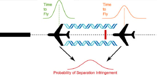
1. Introduction
1.1. Status Quo
1.2. Focus and Structure of The Document
2. Data Preparation
2.1. Data Description
- Flight identifier
- Date and time of arrival or departure (i.e., touch-down/take-off)
- Origin and destination airport
- Runway identifier
- Call sign
- Aircraft type
2.2. Preprocessing
2.2.1. Data Selection
2.2.2. Data Merging
2.2.3. Imputation
2.2.4. Filtering
2.2.5. Feature Transformation
2.3. Exploratory Data Analysis
3. Quantile Regression Forests
3.1. Quantile Regression
3.2. Random Forest
3.3. Model Quality Assessment
3.3.1. Point Estimate Assessment
3.3.2. Probabilistic Prediction Assessment
4. Prediction of Time-To-Fly and Compression Buffer Compensation
4.1. Implementation
4.2. Hyper-Parameter Tuning
4.3. Model Assessment
4.4. Determining the Separation Buffer
4.5. Model Application
5. Conclusions and Outlook
Author Contributions
Funding
Institutional Review Board Statement
Informed Consent Statement
Data Availability Statement
Conflicts of Interest
Abbreviations
| ADS-B | Automatic Dependent Surveillance-Broadcast |
| AIBT | actual in-block time |
| ANSP | air navigation service provider |
| AOBT | actual off-block time |
| ARDT | aircraft ready time |
| ASMA | Arrival Sequencing and Metering Area |
| ATOT | actual take-off time |
| CDF | cumulative distribution function |
| CRPS | continuous ranked probability score |
| ECAC | European Civil Aviation Conference |
| ECDF | empirical cumulative distribution function |
| FAF | final approach fix |
| IAS | indicated air speed |
| ILS | instrument landing system |
| LOC | localizer |
| LORD | Leading Optimised Runway Delivery |
| LoS | loss of separation |
| MAE | mean absolute error |
| MAPE | mean absolute percentage error |
| METAR | meteorological aerodrome report |
| ML | machine learning |
| MTOM | maximum take-off mass |
| probability density function | |
| PL | pinball loss |
| QRF | quantile regression forest |
| RECAT-EU | re-categorisation of ICAO wake turbulence separation |
| RMSE | root mean squared error |
| TAS | true air speed |
| TMA | terminal maneuvering area |
References
- ICAO. Procedures for Air Navigation Services—Air Traffic Management (PANS-ATM, Doc 4444); ICAO: Montreal, QC, Canada, 2007. [Google Scholar]
- ICAO. Air Traffic Services Planning Manual (Doc 9426); ICAO: Montreal, QC, Canada, 1984. [Google Scholar]
- FAA. JO 7110.65Y-Air Traffic Control; FAA: Washington, DC, USA, 2019.
- NATS. Aeronautical Information Circular P 092/2017; Technical Report; UK Aeronautical Information Services; NATS: Whiteley, Fareham, UK, 2017. [Google Scholar]
- Eurocontrol. European Aviation in 2040—Challenges of Growth Summary Report; Eurocontrol: Brussels, Belgium, 2018. [Google Scholar]
- Rooseleer, F.; Treve, V. RECAT-EU-European Wake Turbulence Categorisation and Separation Minima on Approach and Departure; Technical Report; Eurocontrol: Brussels, Belgium, 2015. [Google Scholar]
- Eurocontrol. Specification for Time Based Separation (TBS) for Final Approach; Technical Report; Eurocontrol: Brussels, Belgium, 2016. [Google Scholar]
- Holzäpfel, F.; Gerz, T.; Frech, M.; Tafferner, A.; Köpp, F.; Smalikho, I.; Rahm, S.; Hahn, K.U.; Schwarz, C. The Wake Vortex Prediction and Monitoring System WSVBS Part I: Design. Air Traffic Control Q. 2009, 17, 301–322. [Google Scholar] [CrossRef]
- Airports Council International Europe. SESAR and the Digital Transformation of Europe’s Airports. 2018. Available online: https://www.sesarju.eu/sites/default/files/documents/reports/SESAR and the digital transformation of europe airports.pdf (accessed on 25 January 2021).
- European Commission. Commission Implementing Regulation (EU) No 1207/2011; European Commission: Brussels, Belgium, 2011. [Google Scholar]
- European Commission. Commission Implementing Regulation (EU) No 2017/386; European Commission: Brussels, Belgium, 2017. [Google Scholar]
- FAA. 14 CFR, FAR Section 91.225 “Automatic Dependent Surveillance-Broadcast (ADS-B) Out Equipment and Use"; FAA: Washington, DC, USA, 2015.
- Schäfer, M.; Strohmeier, M.; Lenders, V.; Martinovic, I.; Wilhelm, M. Bringing up OpenSky: A large-scale ADS-B sensor network for research. In Proceedings of the 13th International Symposium on Information Processing in Sensor Networks, Berlin, Germany, 15–17 April 2014; pp. 83–94. [Google Scholar]
- Delovski, T.; Werner, K.; Rawlik, T.; Behrens, J.; Bredemeyer, J.; Wendel, R. ADS-B over Satellite The world’s first ADS-B receiver in Space. In Proceedings of the Small Satellites Systems and Services Symposium, Majorca, Spain, 26–30 May 2014. [Google Scholar]
- SESAR Deployment Manager. ADS-B and Other Means of Surveillance Implementation Status; SESAR Joint Undertaking: Brussels, Belgium, 2018. [Google Scholar]
- Moreno-Torres, J.G.; Raeder, T.; Alaiz-Rodríguez, R.; Chawla, N.V.; Herrera, F. A unifying view on dataset shift in classification. Pattern Recognit. 2012, 45, 521–530. [Google Scholar] [CrossRef]
- Murdoch, W.J.; Singh, C.; Kumbier, K.; Abbasi-Asl, R.; Yu, B. Definitions, methods, and applications in interpretable machine learning. Proc. Natl. Acad. Sci. USA 2019, 116, 22071–22080. [Google Scholar] [CrossRef]
- Basora, L.; Courchelle, V.; Bedouet, J.; Dubot, T. Occupancy Peak Estimation from Sector Geometry and Traffic Flow Data. In Proceedings of the 8th SESAR Innovation Days, Salzburg, Austria, 3–6 December 2018. [Google Scholar]
- Gariel, M.; Srivastava, A.N.; Feron, E. Trajectory clustering and an application to airspace monitoring. IEEE Trans. Intell. Transp. Syst. 2011, 12, 1511–1524. [Google Scholar] [CrossRef]
- Basora, L.; Morio, J.; Mailhot, C. A Trajectory Clustering Framework to Analyse Air Traffic Flows. In Proceedings of the 7th SESAR Innovation Days, Belgrade, Serbia, 28–30 November 2017. [Google Scholar]
- Olive, X.; Morio, J. Trajectory clustering of air traffic flows around airports. Aerosp. Sci. Technol. 2019, 84, 776–781. [Google Scholar] [CrossRef]
- Olive, X.; Grignard, J.; Dubot, T.; Saint-Lot, J. Detecting Controllers’ Actions in Past Mode S Data by Autoencoder-Based Anomaly Detection. In Proceedings of the 8th SESAR Innovation Days, Salzburg, Austria, 3–6 December 2018. [Google Scholar]
- Das, S.; Matthews, B.L.; Srivastava, A.N.; Oza, N.C. Multiple kernel learning for heterogeneous anomaly detection: Algorithm and aviation safety case study. In Proceedings of the 16th International Conference on Knowledge Discovery and Data Mining, Washington, DC, USA, 24–28 July 2010; pp. 47–56. [Google Scholar]
- Olive, X.; Bieber, P. Quantitative Assessments of Runway Excursion Precursors using Mode S data. In Proceedings of the 8th International Conference for Research in Air Transportation, Barcelona, Spain, 26–29 June 2018. [Google Scholar]
- Basora, L.; Olive, X.; Dubot, T. Recent Advances in Anomaly Detection Methods Applied to Aviation. Aerospace 2019, 6, 117. [Google Scholar] [CrossRef]
- Lv, Y.; Duan, Y.; Kang, W.; Li, Z.; Wang, F. Traffic flow prediction with big data: A deep learning approach. IEEE Trans. Intell. Transp. Syst. 2015, 16, 865–873. [Google Scholar] [CrossRef]
- Di Ciccio, C.; Van der Aa, H.; Cabanillas, C.; Mendling, J.; Prescher, J. Detecting flight trajectory anomalies and predicting diversions in freight transportation. Decis. Support Syst. 2016, 88, 1–17. [Google Scholar] [CrossRef]
- Liu, Y.; Hansen, M.; Lovell, D.J.; Ball, M.O. Predicting Aircraft Trajectory Choice—A Nominal Route Approach. In Proceedings of the 8th International Conference for Research in Air Transportation, Barcelona, Spain, 26–29 June 2018. [Google Scholar]
- Gerdes, I.; Temme, A.; Schultz, M. Dynamic airspace sectorisation for flight-centric operations. Transp. Res. Part C Emerg. Technol. 2018, 95, 460–480. [Google Scholar] [CrossRef]
- Gerdes, I.; Temme, A.; Schultz, M. From free-route air traffic to an adapted dynamic main-flow system. Transp. Res. Part C Emerg. Technol. 2020, 115, 102633. [Google Scholar] [CrossRef]
- Herrema, F.; Curran, R.; Hartjes, S.; Ellejmi, M.; Bancroft, S.; Schultz, M. A machine learning model to predict runway exit at Vienna airport. Transp. Res. Part E Logist. Transp. Rev. 2019, 131, 329–342. [Google Scholar] [CrossRef]
- Schultz, M.; Rosenow, J.; Olive, X. A-CDM Lite: Situation awareness and decision making for small airports based on ADS-B data. In Proceedings of the 9th SESAR Innovation Days, Athens, Greece, 2–6 December 2019. [Google Scholar]
- Reitmann, S.; Alam, S.; Schultz, M. Advanced Quantification of Weather Impact on Air Traffic Management-Intelligent Weather Categorization with Machine Learning. In Proceedings of the 13th USA/Europe ATM R&D Seminar, Vienna, Austria, 17–21 June 2019. [Google Scholar]
- Schultz, M.; Reitmann, S. Machine learning approach to predict aircraft boarding. Transp. Res. Part C: Emerg. Technol. 2019, 98, 391–408. [Google Scholar] [CrossRef]
- Sun, J.; Ellerbroek, J.; Hoekstra, J.M. Aircraft initial mass estimation using Bayesian inference method. Transp. Res. Part C Emerg. Technol. 2018, 90. [Google Scholar] [CrossRef]
- Sun, J. Open Aircraft Performance Modeling Based on an Analysis of Aircraft Surveillance Data. Ph.D. Thesis, Delft University of Technology, Delft, The Netherlands, 2019. [Google Scholar]
- Schultz, M.; Olive, X.; Rosenow, J.; Fricke, H.; Alam, S. Analysis of airport ground operations based on ADS-B data. In Proceedings of the 1st conference on Artificial Intelligence and Data Analytics for Air Transportation, Singapore, 3–4 February 2020. [Google Scholar]
- Chatterji, G. Short-term trajectory prediction methods. In Proceedings of the Guidance, Navigation, and Control Conference and Exhibit, Portland, OR, USA, 9–11 August 1999. [Google Scholar] [CrossRef]
- Radišić, T.; Krajček, K.; Kovačić, I. 4D Trajectory Prediction for Arrival and Approach Phases of Flight. International Navigation Conference 2010. 2010. Available online: https://bib.irb.hr/datoteka/858355.Radii_Krajek_Kovai_-_4D_Trajectory_Prediction_for_Arrival_and_Approach_Phases_of_Flight.pdf (accessed on 25 January 2021).
- Paek, H.; Lee, K.; Vela, A.E. En-route Arrival Time Prediction using Gaussian Mixture Model. In Proceedings of the 9th International Conference on Research and Air Transportation (ICRAT), Virtual Event, 15 September 2020. [Google Scholar]
- Wang, Z.; Liang, M.; Delahaye, D. Automated data-driven prediction on aircraft Estimated Time of Arrival. J. Air Transp. Manag. 2020, 88, 101840. [Google Scholar] [CrossRef]
- Ayhan, S.; Samet, H. Aircraft Trajectory Prediction Made Easy with Predictive Analytics. In Proceedings of the 22nd ACM SIGKDD International Conference on Knowledge Discovery and Data Mining, San Francisco, CA, USA, 13–17 August 2016; Association for Computing Machinery: New York, NY, USA, 2016. KDD ’16. pp. 21–30. [Google Scholar] [CrossRef]
- Liu, Y.; Hansen, M. Predicting Aircraft Trajectories: A Deep Generative Convolutional Recurrent Neural Networks Approach. arXiv 2018, arXiv:1812.11670. [Google Scholar]
- Zeng, W.; Quan, Z.; Zhao, Z.; Xie, C.; Lu, X. A Deep Learning Approach for Aircraft Trajectory Prediction in Terminal Airspace. IEEE Access 2020, 8, 151250–151266. [Google Scholar] [CrossRef]
- Tielrooij, M.; Borst, C.; van Paassen, M.M.; Mulder, M. Predicting Arrival Time Uncertainty from Actual Flight Information. In Proceedings of the 11th USA/Europe Air Traffic Management Research and Development Seminar (ATM2015), Lisbon, Portugal, 23–26 June 2015. [Google Scholar]
- Takeichi, N.; Yamada, T.; Senoguchi, A.; Koga, T. Development of a Flight Time Uncertainty Model for Four-Dimensional Trajectory Management. J. Air Transp. 2020, 28, 134–143. [Google Scholar] [CrossRef]
- Tielrooij, M.; Borst, C.; Mulder, M. Supporting Arrival Management Decisions by Visualising Uncertainty. In Proceedings of the 3rd SESAR Innovation Days, Stockholm, Sweden, 26–28 November 2013. [Google Scholar]
- Barratt, S.T.; Kochenderfer, M.J.; Boyd, S.P. Learning Probabilistic Trajectory Models of Aircraft in Terminal Airspace From Position Data. IEEE Trans. Intell. Transp. Syst. 2019, 20, 3536–3545. [Google Scholar] [CrossRef]
- Rocha Murça, M.C.; de Oliveira, M. A Data-Driven Probabilistic Trajectory Model for Predicting and Simulating Terminal Airspace Operations. In Proceedings of the 2020 AIAA/IEEE 39th Digital Avionics Systems Conference (DASC), Virtual Event, 11–15 October 2020; pp. 1–7. [Google Scholar] [CrossRef]
- Herrema, F.; Treve, V.; Curran, R. Typical additional spacing-buffer to apply at 4DME for delivering separation minima. In Proceedings of the 34th Digital Avionics Systems Conference (DASC), Prague, Czech Republic, 13–17 September 2015. [Google Scholar] [CrossRef]
- Herrema, F.; Curran, R.; Treve, V.; Visser, H.G. Evaluation of feasible machine learning techniques for predicting the time to fly and aircraft speed profile on final approach. In Proceedings of the 7th International Conference on Research and Air Transportation (ICRAT), Philadelphia, PA, USA, 20–24 June 2016. [Google Scholar]
- van Baren, G.; Treve, V.; Herrema, F. Predicting time to fly on final approach for optimized delivery of separation. In Proceedings of the Integrated Communications Navigation and Surveillance (ICNS), Herndon, VA, USA, 19–21 April 2016. [Google Scholar] [CrossRef]
- Cappellazzo, V.; Treve, V.; De Visscher, I.; Chalon-Morgan, C. Design Principles for a Separation Support Tool Allowing Optimized Runway Delivery. In Proceedings of the Aviation, Technology, Integration, and Operations Conference, Atlanta, GA, USA, 25–29 June 2018. [Google Scholar] [CrossRef]
- Cappelleras, L. Additional ASMA Time Performance Indicator Document; Eurocontrol Performance Review Unit: Brussels, Belgium, 2015. [Google Scholar]
- Valor, G.B.; López, D.J.M.G. OGIMET—Professional Information about Meteorological Conditions in the World. Available online: http://www.ogimet.com (accessed on 23 January 2020).
- Schultz, M.; Lorenz, S.; Schmitz, R.; Delgado, L. Weather impact on airport performance. Aerospace 2018, 5, 109. [Google Scholar] [CrossRef]
- Förster, S.; Fricke, H.; Vogel, M. Using Agent-Based Modeling to Determine Collision Risk in Complex TMA Environments. In Proceedings of the 8th International Conference on Research in Air Transportation (ICRAT), Barcelona, Spain, 26–29 June 2018. [Google Scholar]
- Förster, S.; Fricke, H.; Rabiller, B.; Hickling, B.; Favennec, B.; Zeghal, K. Analysis of safety performances for parallel approach operations with performance based navigation. In Proceedings of the 19th USA/Europe Air Traffic Management Research and Development Seminar (ATM Seminar), Vienna, Austria, 17–21 June 2019. [Google Scholar]
- Takeuchi, I.; Le, Q.V.; Sears, T.D.; Smola, A.J. Nonparametric quantile estimation. J. Mach. Learn. Res. 2006, 7, 1231–1264. [Google Scholar]
- Meinshausen, N. Quantile regression forests. J. Mach. Learn. Res. 2006, 7, 983–999. [Google Scholar]
- Breiman, L. Random forests. Mach. Learn. 2001, 45, 5–32. [Google Scholar] [CrossRef]
- Hyndman, R.J.; Koehler, A.B. Another look at measures of forecast accuracy. Int. J. Forecast. 2006, 22, 679–688. [Google Scholar] [CrossRef]
- Koenker, R.; Bassett, G. Regression Quantiles. Econometrica 1978, 46, 33–50. [Google Scholar] [CrossRef]
- Matheson, J.E.; Winkler, R.L. Scoring Rules for Continuous Probability Distributions. Manag. Sci. 1976, 22, 1087–1096. [Google Scholar] [CrossRef]
- Hersbach, H. Decomposition of the Continuous Ranked Probability Score for Ensemble Prediction Systems. Weather Forecast. 2000, 15, 559–570. [Google Scholar] [CrossRef]
- Laio, F.; Tamea, S. Verification tools for probabilistic forecasts of continuous hydrological variables. Hydrol. Earth Syst. Sci. 2007, 11, 1267–1277. [Google Scholar] [CrossRef]
- Jordan, A.; Krüger, F.; Lerch, S. Evaluating probabilistic forecasts with scoringRules. arXiv 2017, arXiv:stat.CO/1709.04743. [Google Scholar] [CrossRef]
- Ben Taieb, S.; Huser, R.; Hyndman, R.J.; Genton, M.G. Forecasting Uncertainty in Electricity Smart Meter Data by Boosting Additive Quantile Regression. IEEE Trans. Smart Grid 2016, 7, 2448–2455. [Google Scholar] [CrossRef]
- Python Software Foundation. Python Language Reference; Version 3.8; Python Software Foundation: Wilmington, DE, USA, 2020. [Google Scholar]
- R Core Team. R: A Language and Environment for Statistical Computing; R Foundation for Statistical Computing: Vienna, Austria, 2020. [Google Scholar]
- Pedregosa, F.; Varoquaux, G.; Gramfort, A.; Michel, V.; Thirion, B.; Grisel, O.; Blondel, M.; Prettenhofer, P.; Weiss, R.; Dubourg, V.; et al. Scikit-learn: Machine Learning in Python. J. Mach. Learn. Res. 2011, 12, 2825–2830. [Google Scholar]
- Meinshausen, N. quantregForest: Quantile Regression Forests, R Package Version 1.3-7; 2017. Available online: https://mobile.jmlr.org/papers/volume7/meinshausen06a/meinshausen06a.pdf (accessed on 25 January 2021).
- Scikit-Garden. Available online: https://scikit-garden.github.io (accessed on 23 January 2020).


| RMSE | MAPE | MAE | CRPS |
|---|---|---|---|
| 6.3 s | 2.2% | 4.3 s | 3.1 s |
Publisher’s Note: MDPI stays neutral with regard to jurisdictional claims in published maps and institutional affiliations. |
© 2021 by the authors. Licensee MDPI, Basel, Switzerland. This article is an open access article distributed under the terms and conditions of the Creative Commons Attribution (CC BY) license (http://creativecommons.org/licenses/by/4.0/).
Share and Cite
Förster, S.; Schultz, M.; Fricke, H. Probabilistic Prediction of Separation Buffer to Compensate for the Closing Effect on Final Approach. Aerospace 2021, 8, 29. https://doi.org/10.3390/aerospace8020029
Förster S, Schultz M, Fricke H. Probabilistic Prediction of Separation Buffer to Compensate for the Closing Effect on Final Approach. Aerospace. 2021; 8(2):29. https://doi.org/10.3390/aerospace8020029
Chicago/Turabian StyleFörster, Stanley, Michael Schultz, and Hartmut Fricke. 2021. "Probabilistic Prediction of Separation Buffer to Compensate for the Closing Effect on Final Approach" Aerospace 8, no. 2: 29. https://doi.org/10.3390/aerospace8020029
APA StyleFörster, S., Schultz, M., & Fricke, H. (2021). Probabilistic Prediction of Separation Buffer to Compensate for the Closing Effect on Final Approach. Aerospace, 8(2), 29. https://doi.org/10.3390/aerospace8020029