Article

Dynamic Modeling and Analysis of Impact in Space Operation Tasks

1
College of Aerospace Science and Engineering, National University of Defense Technology, Changsha 410000, China
2
Institute of Telecommunication and Navigation Satellites, China Academy of Space Technology, Beijing 100094, China
*
Author to whom correspondence should be addressed.
Aerospace 2021, 8(12), 381; https://doi.org/10.3390/aerospace8120381
Submission received: 21 October 2021 / Revised: 26 November 2021 / Accepted: 3 December 2021 / Published: 6 December 2021
(This article belongs to the Section Aeronautics)

Abstract

:
For the rigid impact and flexible impact in space operation tasks, impact dynamic models between two objects are established in this paper, laying the model foundation for controlling or suppressing the impact. For the capture task between a grapple shaft and a rigid body, the impact dynamic model is established based on the Zhiying–Qishao model. Moreover, by introducing a friction factor into the original impact model, an improved dynamic model between two rigid bodies is proposed. For the capture task with flexible impact, an impact dynamic model between the grapple shaft and a flexible wire rope is established based on the dynamic model of the flexible wire rope. The ground experiments and simulations are carried out with two objects on an air flow table. The experiment results validate the impact dynamic model proposed in this paper.

1. Introduction

In recent years, with the deepening of space exploration, many space operation tasks need to be completed, such as satellite acquisition, cabin docking and assembly, load handling, and so on. In this process, the active object inevitably impacts on the operation target. Unlike the ground environment, the space target is located in a weightless environment [1]. It moves freely under the reaction force and moment generated during contact and impact. Sometimes, a small external impact influences the whole system significantly, affecting its posture and stability and even causing the failure of the capture task. Therefore, it is necessary to study the impact between space operation objects, which will lay the foundation for controlling or suppressing the impact.
In the process of contact and impact, the capture device contacts directly with the target load, whose structural characteristics have a direct influence on the capture task. Capture devices can be divided into rigid capture devices, flexible capture devices, and rigid flexible coupling capture devices, according to their contact characteristics [2]. A capture device with rigid parts is called a rigid capture device, which has the advantages of a simple structure design, relatively mature technology, easy control, and high connection rigidity [3]. A device using flexible parts for capture is called a flexible capture device. Compared to the rigid capture device, the impact of the flexible capture device is smaller due to the contact of flexible parts. Meanwhile, the flexible capture device can easily achieve a wide range of capture and has a strong tolerance. These characteristics reduce the accuracy requirements of the relative pose between the capture device and the target load. The flexible capture device mainly contains three flexible wire ropes, which can realize flexible capture and rigid connection at the same time, and the operation is relatively simple. It has been widely used in the typical space manipulators, such as the SSRMS [4] in Canada and the JEM Remote Manipulator System (JEMRMS) [5] in Japan. It is more suitable for a task with a noncooperative target, such as space debris cleaning and waste satellite recovery tasks [6]. Through reasonable structural design, it perfectly inherits the advantages of the rigid capture device such as a high connection stiffness, and owns unique advantages such as a strong tolerance and a small impact. The reduction of impact will reduce the influence of external impact on the combined system, increasing its stability and decreasing the possibility of capture failure.
An impact between two objects is a complex phenomenon that occurs in a very short period when two or more bodies collide. During the impact period, a high force is applied, causing a quick change of the objects’ velocity and kinematic restoration, release, and transfer to another object of kinematic energy. To study this, the impact period is divided into a compression phase and a restitution phase [7]. When the objects start to contact, the compression phase begins. This phase terminates with the normal relative velocity of the contact objects going to zero. Then, the restitution phase begins until the objects separate.
There are two different approaches for impact analysis. The first approach is called impulse–momentum or discrete method, which assumes that the interaction between the objects occurs in a short time and the outside force can be ignored. To simulate the process of energy transfer and dissipation, a restitution coefficient is employed, which can be defined by Newton’s model [8] and Poisson’s model [9]. However, these methods have been confined primarily to an impact between rigid bodies [10]. The situation is complicated in some more general cases that involve multiple contacts and intermittent contact.
Therefore, the continuous method was proposed since the interaction forces act continuously during the impact. There are three important continuous impact models based on the penetration depth [9]: Kelvin–Voigt model, Hertz model, and Hunt–Crossley model. The Kelvin–Voigt is the simplest model, which simulates the force with a parallel spring-damper element [11]. Meanwhile, there are three common problems with this model: first, the damping force is not zero upon initial contact; second, the forces between the objects exhibit tension property before leaving contact; third, determining the coefficient of restitution depends on experience [12,13]. The Hertz model [14,15] increased the accuracy of the stiffness portion of the impact force by approximating the stress distribution in the contact region based on the theory of elasticity. Based on this model, Liu [16] and Qiao [17] studied the dynamics of a space robot when capturing a floating target. Kosenko [18] proposed an invariant form for the force function, which depends on the geometric properties of an intersection for undeformed rigid bodies’ volumes; therefore, this model was called volumetric model. It can realize the computational reduction. However, the Hertz model is still limited to an impact with elastic deformation and its original form does not include damping. To overcome the disadvantages of the Kelvin–Voigt model and to retain the advantages of the Hertz model, Hunt [19] proposed an alternative model for energy dissipation, which includes a non-linear damping term. From Hunt and Crossley’s model, many other nonlinear damping models were proposed, such as that of Gonthier [20] and Zhiying–Qishao [21]. However, the only difference between them was the definition of the damping parameter. Recently, Andre [13] extended Gonthier et al.’s work by proposing an alternate damping model based on material properties. The advantage was that the damping factor was a constant internal material property, which depended only on the material and not on the impact velocity or the contact geometry.
All the literature surveyed above considered an ideal environment, which ignores the interference of friction. However, when the impact occurs at a low velocity, the friction cannot be ignored. As a result, this paper introduces a friction parameter into the nonlinear model, extending it to the normal condition. Though the influence of friction does not exist in real space capture task, it cannot be eliminated or ignored in ground experiment. To fit the condition of ground experiment, a friction parameter was introduced to the impact model. Moreover, based on the experimental testbed, some experiments were carried out, and the experimental data were compared with theoretical result, which can verify the advantage of the improved nonlinear model.
The research of discrete impact dynamics and continuous impact dynamics focuses on the impact between rigid bodies but does not consider the flexible impact between flexible objects such as flexible wire ropes. Aiming at the impact problem of the flexible wire rope, the impact model becomes very complex. The discrete impact dynamics can only be successfully applied for flexible wire ropes when the duration of impact, the change rule of impact force with time, the contact velocity and the depth of the contact zone can be calculated. These parameters cannot always be calculated especially when the dynamic model is very complex, so continuous impact dynamics is more suitable for impact modeling of flexible ropes than discrete impact dynamics. It is necessary to modify the continuous impact model with the help of the dynamic model of the flexible wire rope. For the dynamic modeling of a flexible wire rope, Russel et al. [22] regarded the flexible wire rope as a discrete model composed of several rigid rods, which had a concentrated mass and were connected by pins. Aiming at the motion of tethered satellite, Carter et al. [23] used the lumped mass model to divide the tethered satellite into several small segments. The mass of each segment was concentrated at the end point, and the adjacent particles were connected by a retractable spring damper. Tan et al. [24] proposed a plane bending flexible wire rope model based on a torsional damping spring. Through adding a driving force at the end of the flexible wire rope, they established the force and torque balance equations of the system. This method simplified the modeling process of a flexible wire rope, but the tensile characteristics of flexible wire rope were not considered. Pan et al. [25] discretized the flexible wire rope into a group of element beam models. The adjacent elements were connected by six-dimensional force/moment to fully consider the deformation characteristics of the rope, such as tension, shear, bending, and torsion. Based on this, the relation between the force and relative displacement of each discrete segment was established. The existing research on the impact modeling of a flexible wire rope is scarce, and most research works directly regard the contact action with a flexible wire rope as a collision pulse or known force [26,27]. With the establishment of the dynamic model of a flexible wire rope in [25,28], the Hertz contact theory was directly used to obtain the impact force model. However, because the impact between an object and a flexible wire rope is accompanied by large flexible geometric deformations and local micro deformations of the flexible wire rope, the expression results of this method are insufficient. Besides, the existing studies about continuous impact modeling of a flexible wire rope mainly consider the impact between two single bodies. This kind of method rely on the initial position and velocity of the two objects, and there is a conflict between the calculation speed and calculation accuracy. Meanwhile, the existing related studies have offered few clear standards on choosing a model to describe the impact of a flexible wire rope.
According to the above investigation, the current research on the impact between objects is mainly divided into discrete impact dynamics and continuous impact dynamics. Discrete impact dynamics mainly depends on the classical theory of coefficient of restitution, which is simple and efficient. The dynamic model of continuous impact mainly depends on Hertz’s theory, which can display the impact force. In addition, there are few studies on the impact force model of a flexible wire rope with large flexibility at present. The existing methods of impact modeling of a flexible wire rope are mainly based on continuous impact modeling. Such methods usually assume impact between single bodies rather than multiple bodies, and there is a conflict between calculation speed and accuracy. The existing research also offers few clear standards on what model to choose for impact modeling of flexible rope wires. As a result, how to derive the impact force model of a flexible wire rope based on the existing contact impact theory needs further research.
This paper is organized as follows. In Section 2, based on Zhiying and Qishao’s nonlinear model, the impact dynamic model between a grapple shaft and a rigid body is established. Then, friction is introduced into the impact dynamic model of two objects, making it close to actual impact cases. In Section 3, the impact dynamic model between a grapple shaft and a flexible wire rope is established. In Section 4, the ground experimental testbed is first constructed, and impact experiments and simulations of the two satellite simulators are then carried out. Section 5 is the conclusion.

2. Impact Dynamics between Grapple Shaft and Rigid Body

In this section, an impact dynamic model between a grapple shaft and a rigid body is established to simulate the case of a rigid capture device capturing a rigid body object. As mentioned in Section 1, a continuous impact dynamic model is suitable for general impact cases and the interaction force during the impact acts in a continuous manner. As a result, the continuous impact dynamic model was applied. Generally, the continuous impact dynamic model includes three types: linear damping model, Hertz model, and nonlinear damping model. The nonlinear model not only absorbs the advantages of Hertz model, such as the relatively accuracy in the stiffness portion of the impact force, but also considers the energy loss during the impact process. Therefore, this section adopts the nonlinear damping model to establish the impact dynamic model of two objects without friction. In addition, since the capture target may be affected by friction in actual space capture tasks, the friction is then introduced into the impact dynamic model.

2.1. Impact Dynamic Modeling of a Rigid Body

For two objects, their impact dynamic model based on the nonlinear damping model is:
F = k δ n + λ δ ˙ δ n
where F is the normal impact force, δ is the deformation, λ is the damping parameter, n = 1.5 , and k is the stiffness coefficient of the rigid body.
The damping parameter λ can be constructed by some models, such as Gonthier’s model, Flores’s model, and Zhiying and Qishao’s model. In this paper, the Zhiying–Qishao model is introduced to construct λ , which is shown as follows:
λ = 3 ( 1 c 2 ) e 2 ( 1 c ) 4 k δ ˙ ( )
where c is the restitution coefficient. The value of stiffness coefficient k is decided by the Poisson ratio, Young’s moduli, and the contact radius:
k = 4 3 π ( h 1 + h 2 ) R 1 R 2 R 1 + R 2 1 / 2
where R i   ( i = 1 , 2 ) is the contact radius of the impact objects, and h 1 = ( 1 ξ i ) / π E i , where ξ i is the Poisson ratio and E i is Young’s moduli.
According to the equivalent mass and Newton’s second law, we have:
m δ ¨ = λ δ n δ ˙ k δ n
m = m 1 + m 2 m 1 m 2
where m 1 and m 2 are the impact objects’ mass.
As the relative contact velocity v = δ ˙ , combining with Equation (4), we have:
d v d δ = d v / d t d δ / d t = δ ¨ v = ( a v + ω ) δ n v
where a = λ / m , ω = k / m .
Integrating Equation (6) from the initial contact velocity, the relation between δ and v can be derived as follows:
δ n + 1 = n + 1 a 2 a ( v v 0 ) ω ln a v + ω a v 0 + ω
where v 0 is the initial contact velocity during the contact phase. Since there is no deformation at the initial moment, we can set δ = 0 to obtain v 0 .
Equation (6) is derived as:
d t = d v δ ¨ = d v ( a v + ω ) x n
Substituting Equation (7) into Equation (8), the relation between contact time t and relative contact velocity v is:
t = v 0 v d v ( a v + ω ) n + 1 a 2 a ( v v 0 ) ω ln a v + ω a v 0 + ω n n + 1

2.2. Impact Dynamic Modeling of a Rigid Body Considering Friction

In the actual space capture task, the capture target may be affected by friction. According to Equation (4), the friction force is introduced into the impact dynamic model:
m δ ¨ = λ δ n δ ˙ k δ n + f
Compared with Equations (6) and (10), it can be transformed as follows:
d v d δ = δ ¨ v = = λ δ n δ ˙ k δ n + f m v

3. Impact Dynamic between Grapple Shaft and Flexible Wire Rope

In this section, to study the case of a rope capture mechanism that is used in a flexible capture device, the impact dynamic model between a grapple shaft and a flexible wire rope is established. The flexible capture device can achieve a wide operating range and have strong tolerance, as well as a small impact during a space capture task, which can reduce the possibility of causing plastic deformation on the object. Therefore, flexible capture devices are widely used in actual space capture cases while a rope capture mechanism is applied in such capture devices. Because the flexible wire rope is the main executive element of the rope capture mechanism, the impact problem is essentially aimed at the impact between the flexible wire rope and the target, which is assumed to be a rigid body. Therefore, this section mainly focuses on the impact dynamic modeling of the flexible wire rope. The basic dynamic model of the flexible wire rope is first established. In this stage, the flexible wire rope is first separated into a sequence of nodes and the kinematic relation is obtained with the help of an inertial coordinate system, a fixed coordinate system, and a moving coordinate system. Then, the dynamic model of the flexible wire rope is established with Newton’s second law. Based on the dynamic model, the constraint of the space snare capture is introduced, and the modeling and analysis of the impact between the flexible wire rope and the rigid body object is achieved.
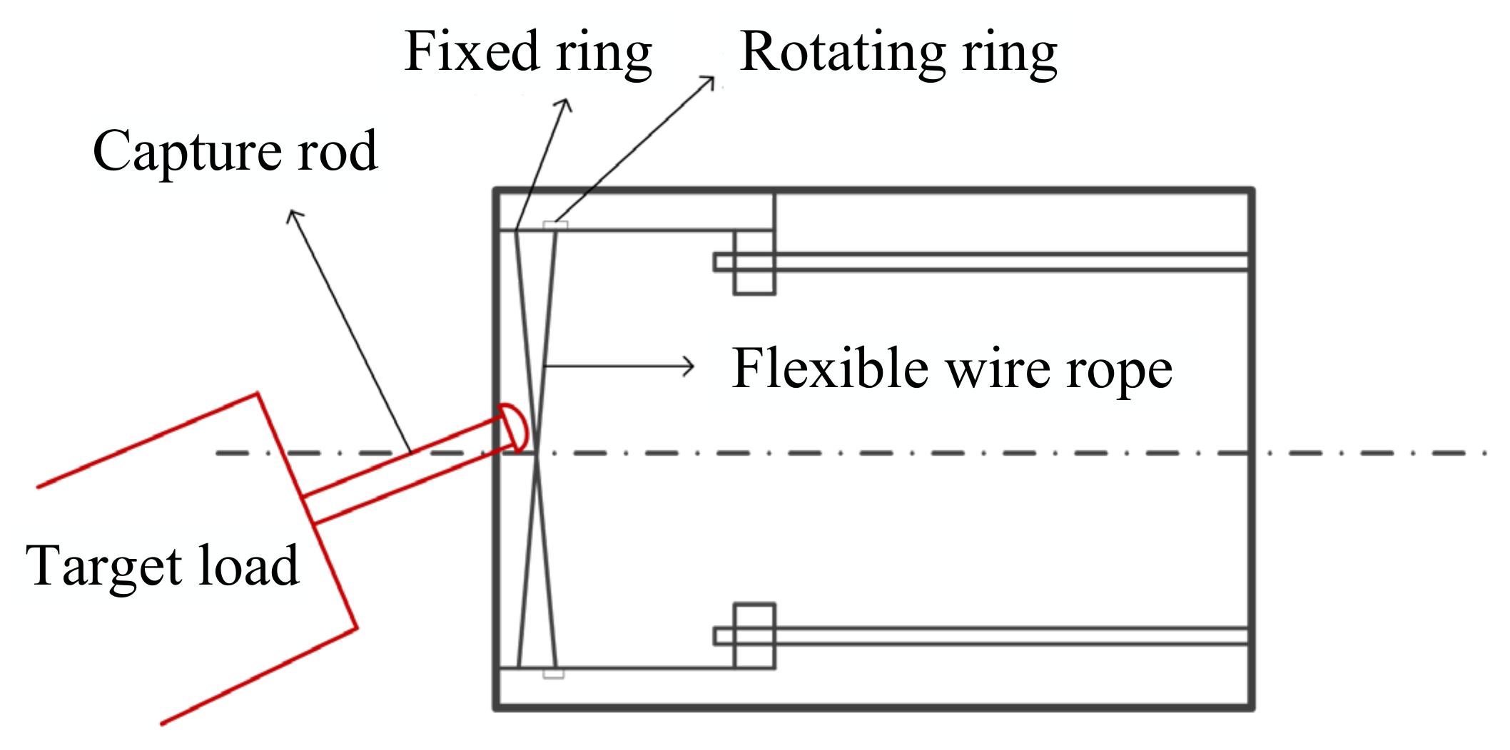
The space snare capture is mainly composed of three modules: a rope catching module, a dragging module, and a locking module, as shown in Figure 1. The rope capture module is to capture the target and limit its free movement in space. This module is installed on the support shell and consists of a fixed ring, a rotating ring, and three flexible wire ropes. For each flexible wire rope, one end is installed on the fixed ring (called fixed point), while the other end is connected with the rotating ring and rotates with it (called moving point). When the driver drives the rotating ring to rotate, three flexible wire ropes begin to move with it, and the closed capture area gradually shrinks and finally locks the target payload. The exact capturing steps are as follows:
Step 1: The space manipulator carries the space snare capture device near the target load, locating the target load within the capture zone of the three flexible wire ropes.
Step 2: The rotating ring begins to rotate, making the capture zone shrink and the free movement of the target load is gradually limited. During this step, several impacts will occur between the target load and the flexible wire ropes.
Step 3: When the shrinking of the capture zone is finished, the target load is fixed in the center of the capture device. The position and posture of the target load will be adjusted by the dragging module. When the target load fully fits the capture device, the target load is locked by the locking module.

3.1. Dynamic Modeling of the Flexible Wire Rope

In a microgravity environment, the impact between the flexible wire rope and target becomes complex. To obtain the impact force between the grapple shaft and the flexible wire rope, it is necessary to establish a dynamic model of the flexible wire rope first.

3.1.1. Basic Motion Equation of the Flexible Wire Rope

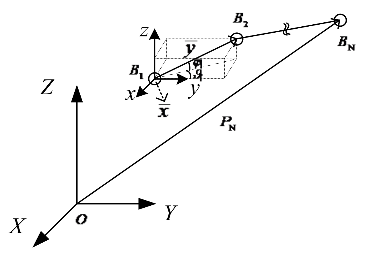
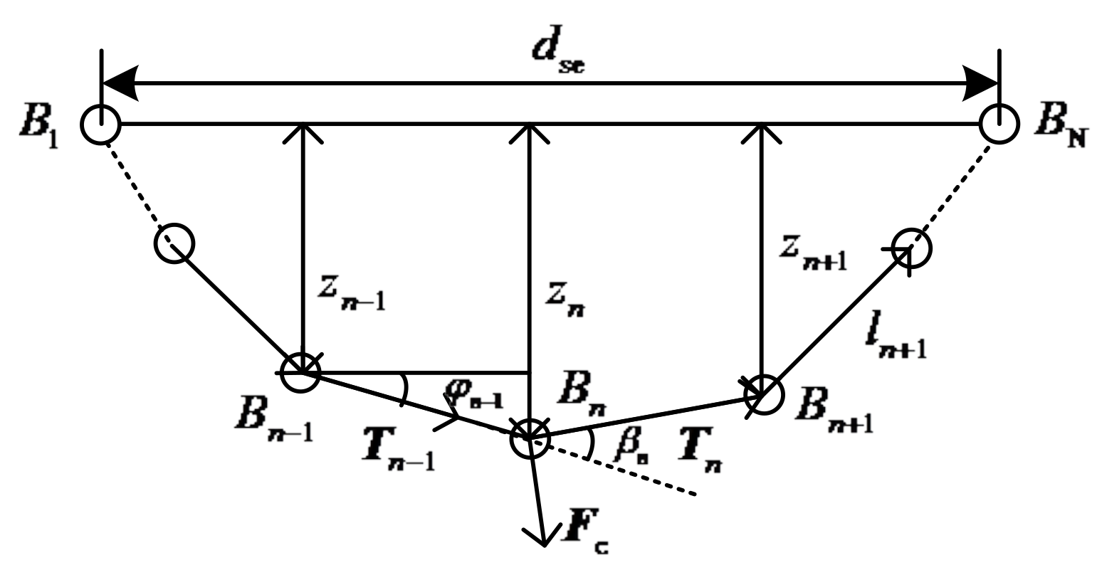
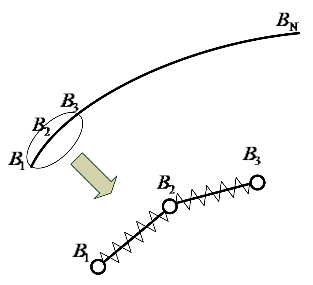
The flexible wire rope is separated into a group of nodes connected in sequence in space. The node number is increased from one end of the rope to the other ( B 1 , B 2 , B 3 , , B N ), and the adjacent nodes are connected by a mass-free tensile spring, which shows the tensile characteristics of the flexible wire rope, as shown in Figure 2.
The external force on the flexible wire rope is concentrated on each node, and with the linear density through the lumped mass method, the mass of each node is determined as:
m i = 1 2 ρ lin A i l ^ i i f i = 1 1 2 ρ lin A i 1 l ^ i 1 + A i l ^ i i f i = 2 ~ N 1 1 2 ρ lin A i 1 l ^ i 1 i f i = N
where ρ lin is the linear density of the flexible wire rope, and A i and l ^ i are the cross-sectional area and original length of the ith section on the flexible wire rope, respectively. If the mass of the flexible wire rope is evenly distributed and the length of discrete section is equal, the mass of each node can be calculated simply as follows:
m i = m tot 2 N 1 i f i = 1 o r i = N m tot N 1 i f i = 2 ~ N 1
where m tot is the total mass of the flexible wire rope.
To describe the motion state of the flexible wire rope, we establish the inertial coordinate system O X Y Z , fixed coordinate system B i x y z , and moving coordinate system B i x ¯ y ¯ z ¯ . The establishment of the coordinate system is shown in Figure 3. The moving coordinate system B i x ¯ y ¯ z ¯ can be obtained by the following steps. First, the coordinate system B i x ¯ y ¯ z ¯ overlaps with B i x y z ; then, rotate the fixed coordinate system B i x y z around the z-axis with angle ϑ i , obtaining a middle coordinate system; finally, rotate the middle coordinate system around the x ¯ -axis with angle φ i . ϑ i and φ i are used to describe the deflection and pitching motion of the flexible wire rope, respectively.
Set the rotation matrix of the dynamic coordinate system B i x ¯ y ¯ z ¯ relative to the fixed coordinate system B i x y z at node i as H i . The rotation matrix H i is the product of the basic rotation matrices around the z-axis and x ¯ -axis.
The basic rotation matrix around the z-axis is:
R ( z , ϑ i ) = c ϑ i s ϑ i 0 s ϑ i c ϑ i 0 0 0 1
where the parameters c and s represent the operator cos and sin, respectively. The basic rotation matrix around the x ¯ -axis is:
R ( x ¯ , φ i ) = 1 0 0 0 c φ i s φ i 0 s φ i c φ i
We consider that the two rotation matrices move around the moving coordinate system B i x ¯ y ¯ z ¯ , which is not a fixed coordinate system. Therefore, the rotation matrix is the result of the product of two rotation matrices from left to right, as shown as follows:
H i = R z , ϑ i R x ¯ , φ i = c ϑ i s ϑ i c φ i s ϑ i s φ i s ϑ i c ϑ i c φ i c ϑ i s φ i 0 s φ i c φ i
Since H i is continuously differentiable in time, its derivative can be expressed as follow [29]:
H ˙ i = S ω i H i
where S ω i is the angular velocity operator matrix, which can be obtained from Equation (17):
S ω i = H ˙ i H i 1 = 0 ϑ ˙ i φ ˙ i s ϑ i θ ˙ i 0 φ ˙ i c ϑ i φ ˙ i s ϑ i φ ˙ i c ϑ i 0
Let ω i = ω i x , ω i y , ω i z T . Since the angular velocity operator matrix is antisymmetric, we define it as follow:
S ω i = 0 ω i z ω i y ω i z 0 ω i x ω i y ω i x 0
Combined with Equations (18) and (19), the rotational angular velocity of the moving coordinate system B i x ¯ y ¯ z ¯ relative to the fixed system B i x y z can be obtained as follows:
ω i = φ ˙ i c ϑ i , φ ˙ i s ϑ i , ϑ ˙ i T
The acceleration of the rotation angle can be derived from Equation (20):
ω ˙ i = φ ¨ i c ϑ i ϑ ˙ i φ ˙ i s ϑ i , φ ¨ i s ϑ i + ϑ ˙ i φ ˙ i c ϑ i , ϑ ¨ i T
Define the length vector of the ith section on the flexible wire rope as l i . Then, the velocity vector can be expressed as:
l ˙ i = l ˙ i j ¯ i + ω i × l i
In Equation (22), the first and second terms on the right of the equation are the speed change caused by the length change and the rotation change of the discrete section, respectively.
By deriving Equation (22), the acceleration vector of the ith section on the flexible wire rope can be obtained as follows:
l ¨ i = l ¨ i j ¯ i + 2 l ˙ i ω i × j ¯ i + l i ω ˙ i × j ¯ i + l i ω i × ω i × j ¯ i
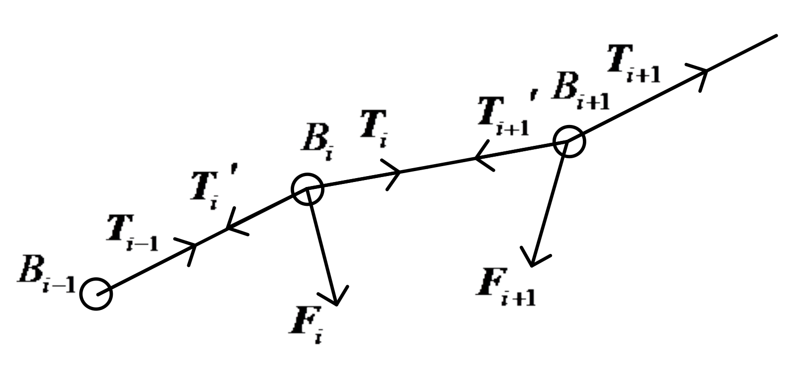
The motion equation of the flexible wire rope is established from the perspective of kinematics, and its motion characteristics are described from the perspective of dynamics. First, the stress on nodes B i , B i + 1 is analyzed, as shown in Figure 4.
According to Newton’s second law, the relation between the acceleration of the ith section on the flexible wire rope and the external force is obtained as follows:
l ¨ i = T i + 1 + T i + 1 + F i + 1 m i + 1 T i + T i + F i m i
where F i = F i x , F i y , F i z T   and   F i + 1 = F ( i + 1 ) x , F ( i + 1 ) y , F ( i + 1 ) z T are the external forces exerted on the nodes B i   and   B i + 1 , respectively. T i , T i and T i + 1 , T i + 1 are the pulling forces exerted on the nodes B i   and   B i + 1 , respectively. According to Newton’s third law, they meet the following constraints:
T i = T i 1 , T i + 1 = T i
T i = k tes Δ l i + c tes l ˙ i
where T i is the amplitude of the vector T i , k tes is the stiffness coefficient of the tension spring, Δ l i is the change of the length of the ith section on the flexible wire rope, and c tes is the damping coefficient of the tension spring.
In the ith moving coordinate system, Equation (24) is also expressed as follows:
l ¨ ¯ i = T ¯ i + 1 + T ¯ i + 1 + F ¯ i + 1 m i + 1 T ¯ i + T ¯ i + F ¯ i m i
H i 1 = H i H i 1 i H i 1 i = H i 1 H i 1
H i + 1 = H i H i + 1 i H i + 1 i = H i 1 H i + 1
According to Equations (28) and (29), the following relations can be further obtained:
T ¯ i 1 = s ϑ i ϑ i 1 c φ i 1 s φ i 1 s φ i + c ϑ i ϑ i 1 c φ i 1 c φ i s φ i 1 c φ i c ϑ i ϑ i 1 c φ i 1 s φ i T i 1
T ¯ i + 1 = s ϑ i + 1 ϑ i c φ i + 1 s φ i s φ i + 1 + c ϑ i + 1 ϑ i c φ i c φ i + 1 c φ i s φ i + 1 c ϑ i + 1 ϑ i s φ i c φ i + 1 T i + 1
F ¯ i = c ϑ i F i x + s ϑ i F i y s ϑ i c φ i F i x + c ϑ i c φ i F i y + s φ i F i z s ϑ i s φ i F i x c ϑ i s φ i F i y + c φ i F i z
F ¯ i + 1 = c ϑ i F ( i + 1 ) x + s ϑ i F ( i + 1 ) y s ϑ i c φ i F ( i + 1 ) x + c ϑ i c φ i F ( i + 1 ) y + s φ i F ( i + 1 ) z s ϑ i s φ i F ( i + 1 ) x c ϑ i s φ i F ( i + 1 ) y + c φ i F ( i + 1 ) z
Combining Equations (23) and (27)–(33), the dynamic equation of the flexible wire rope with deflection angle ϑ , pitch angle φ , and tensile length of discrete section l as state variables can be obtained as follows:
H r x ¨ r + C r x ˙ r , x r + P r x r = F r
where x r = ϑ i , φ i , l i T is the state variable of the flexible wire rope, and H r , C r , P r x r , F r are the inertia matrix, nonlinear term, potential energy term, and equivalent external force term of the flexible wire rope system, respectively.
As a result, the motion equation of the flexible wire rope has been established.

3.1.2. Capture Constraint Analysis of the Snare Capture

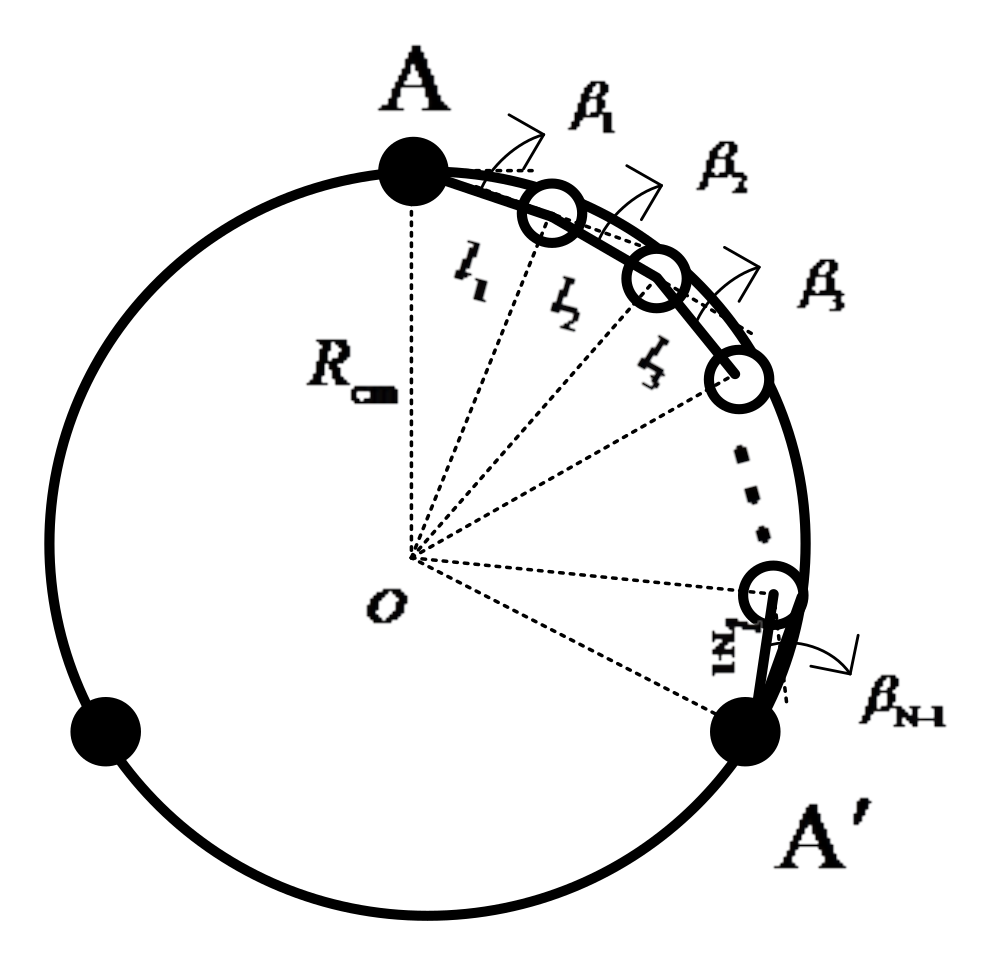
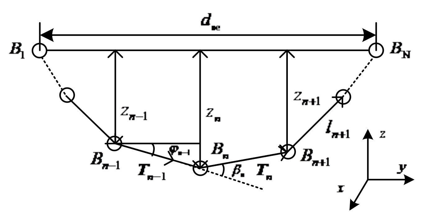
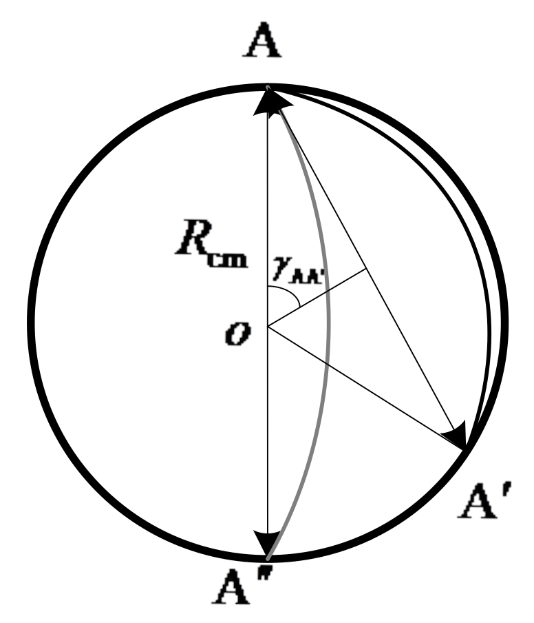
As shown in Figure 5, we assume that the fixed ring and the rotating ring are located at the same plane whose radius is R cm . In the initial state, the end A of the flexible wire rope A A is installed on the fixed ring, and the end A is connected to the rotating ring. The initial angle between the adjacent discrete segments is β 1 , β 2 , , β N 1 , which is initially in a static equilibrium state. To obtain the initial state of the flexible wire rope, a stress analysis is carried out, as shown in Figure 6.
According to Figure 6, the following equilibrium equation for each node can be obtained as follows:
T i 1 + T i + F i , i + F i 1 , i + F i + 1 , i = 0
where T i 1 , T i are the elastic tensions generated at the i-1th and ith section on the flexible wire rope, respectively, and F i , i , F i 1 , i , F i + 1 , i are the equivalent structural forces of the torsion spring generated at nodes B i , B i 1 , and B i + 1 , respectively.
Since Equation (35) can be divided into two groups of scalar equations in direction y and z, a total number of 2 N 2 static force balance equations can be established. In addition, from the perspective of geometric constraints, since the flexible wire rope only moves in the plane yoz, let ϑ i = 0 , and the following two geometric constraint equations can be established simultaneously:
l 1 c φ 1 + l 2 c φ 2 + + l N 1 c φ N 1 = d se l 1 s φ 1 + l 2 s φ 2 + + l N 1 s φ N 1 = 0
where d se is the distance between the beginning and end of the flexible wire rope. Its value range is defined as follows:
(1) When the flexible wire rope is located at the initial position A A (as shown in Figure 7), the minimum value of d se can be calculated according to the following formula:
d se = 2 R cm sin γ A   A  
where γ A   A   represents half of the center angle corresponding to the arc A A .
(2) When the flexible wire rope is located at A A , the maximum value 2 R cm of d se is taken. Therefore, the reasonable range of the distance between the two ends of the flexible wire rope is d se 2 R cm sin γ A   A   , 2 R cm .
So far, a total of 2 N 1 equations have been established, and we have β i = φ i 1 φ i . Since the number of basic unknown variables l i , φ i is 2 N 1 , the equation composed of Equations (35) and (36) can be solved. Then, the tension and bending preloads in the initial state can be obtained as follows:
T i 0 = k tes l i l tot N 1
M i 0 = k tor β i β i 0
where l tot is the total length of the flexible wire rope.

3.2. Impact Modeling and Analysis

To simplify the impact modeling process, some assumptions are made below:
  • The impact force only acts on the node. If the number of nodes is large enough, this could be realized.
  • The relative velocity between the grapple shaft and the flexible wire rope is low enough. Based on this, we assume that the velocity-dependent term makes no contribution to the force equilibrium equation. For the space capture task, the relative velocity between the target object and the capture device at the beginning of contact is controlled at a low level to reduce the impact force. The maximum of this relative velocity is about 0.1 m/s in most cases [29,30,31]. At this velocity level, even if this velocity is considered in the impact dynamic model, the result of the calculated impact force does not vary significantly from that of this paper, considering the difference of mass of the target object [32]. As a result, this assumption is reasonable and able to simplify the calculation process.
  • Considering the small deformation caused by contact, the impact force direction stays the same during the contact process and only a single point contact happens.
When the flexible wire rope is subjected to external force, we assume that there is a virtual spring between the flexible wire rope and the support shell according to its reaction state. One end of the spring is connected to the node of the flexible wire rope while the other end is connected to the support shell. Because the stiffness coefficient of the virtual spring is not constant, the contact impact force cannot be simply calculated according to the Hertz damping model. In fact, the stiffness coefficient of the virtual spring is related to the pressing depth δ v and the distance d se between the beginning and end of the flexible wire rope. The pressing depth is defined as the distance that the flexible wire rope moves in the contact direction from the initial position to the current position, which is shown in Figure 8.
We assume that the contact occurs on node n of the flexible wire rope, and the force condition is shown in Figure 9. The static force equilibrium equations for node 2 ~ N 1 can be established as:
F c T i 1 + T i + F i , i + F i 1 , i + F i + 1 , i = 0 i f i = n T i 1 + T i + F i , i + F i 1 , i + F i + 1 , i = 0 e l s e
where F c is the external force applied on node n.
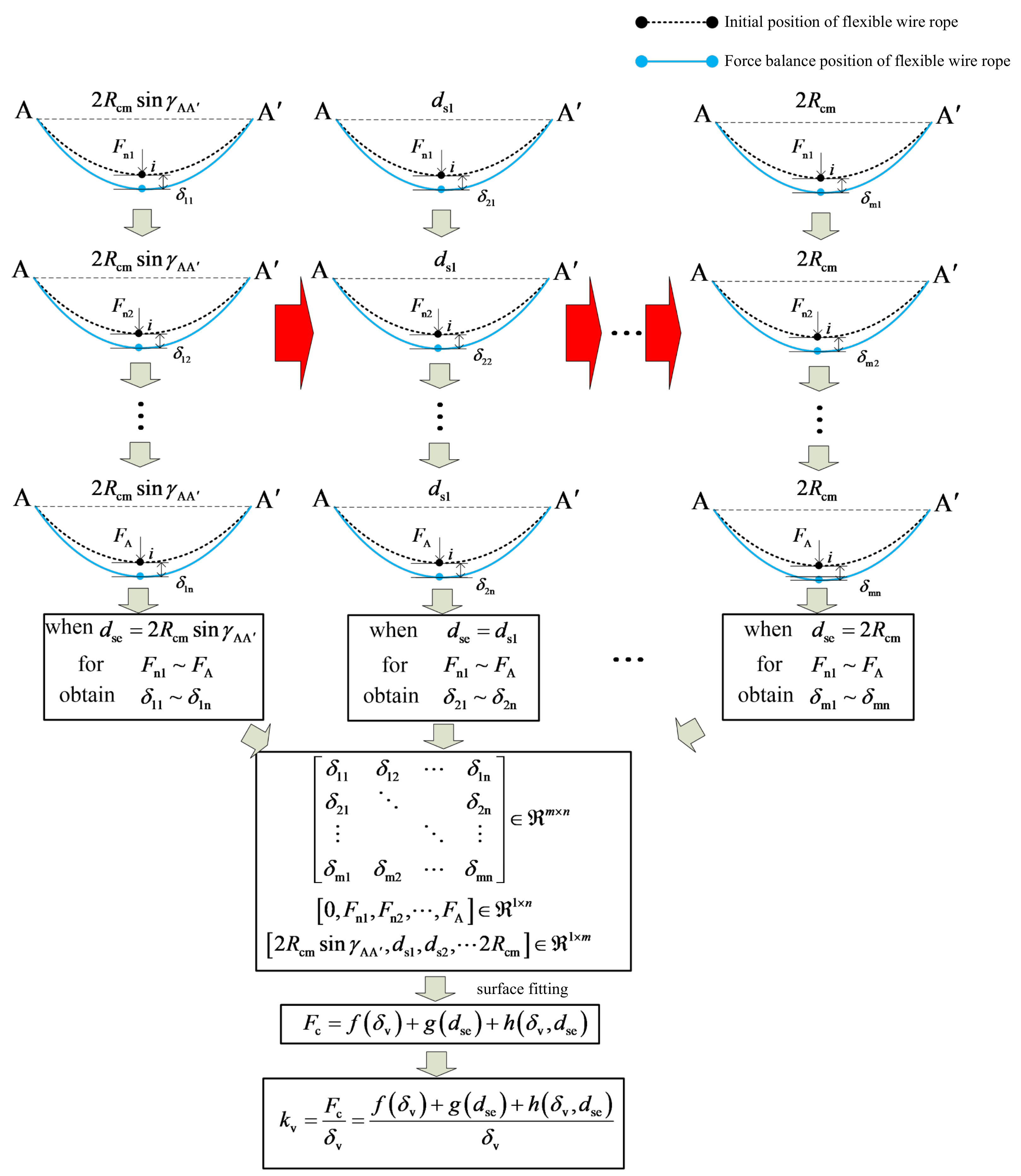
By combining Equation (40) with Equation (36), the equilibrium equations of the flexible wire rope in the presence of an external force can be obtained. When a group of F c and d se is given, the corresponding indentation depth δ v can be obtained. In a sense, the contact condition of the flexible wire rope can be compared with that of a spring. However, the difference is that the stiffness of the flexible wire rope in the contact process is not the only constant. It is related to the pressing depth and the distance between the beginning and end of the flexible wire rope. The stiffness coefficient of the virtual spring is defined as the ratio of the normal pressure at the contact point to the corresponding pressing depth, which can be solved by the following steps.
(1) The initial ranges for d se d min , d max and F c F min , F max are set first. The range of d se is determined by the constraints of the institution. However, the range of F c is set through a tentative process. The minimum value is 0 and the maximum value is first set to be F A .
(2) A set of start–end distances 2 R cm sin γ A   A   , d s 1 , d s 2 , 2 R cm 1 × m with 2 R cm sin γ AA < d s 1 < d s 2 < < 2 R cm , and 0 , F n 1 , F n 2 , , F A 1 × n with 0 < F n 1 < F n 2 < < F A are given. By substituting these values into Equations (36) and (40), the corresponding indentation depth δ v m × n of these values can be obtained. Then, the high-order polynomial is used to fit the surface of the calculation results, and the following functional relation can be obtained as follows:
F c = f δ v + g d se + h δ v , d se
where f δ v   and   g d se are the polynomial functions of δ v   and   d se , respectively, while h δ v , d se represents the coupling function with variables δ v , d se . If the precision of curved surface fitting is not high enough, the method of piecewise fitting can be used.
According to the definition, the expression of the virtual spring contact stiffness coefficient can be obtained as follows:
k v = F c δ v = f δ v + g d se + h δ v , d se δ v
(3) In the process of capturing, when the pressing depth and the distance between the beginning and end of the flexible wire rope are known, the contact stiffness coefficient of the virtual spring can be obtained through Equation (42). The detailed calculation process of the contact stiffness coefficient of the virtual spring is shown in Figure 10. Furthermore, the dynamic contact impact force between the target and the flexible wire rope can be calculated according to the Hertz damping model:
F c = k v δ v + c v δ ˙ v
where δ ˙ v is the relative compression velocity in the contact process.
It is notable that the proposed polynomial function fitting method can be used to calculate the contact stiffness coefficient of the virtual spring of the flexible wire rope, which has a certain scope of application, that is d se d min , d max and F c F min , F max . In the process of capturing, the calculation accuracy can only be guaranteed when the above two variables are within this range. If the static impact force F c max = k v δ v max at the maximum compression position δ v max is greater than the upper limit value of the fitting range F A , the upper limit value F B should be reset to such a value F B > F c max , and the above calculation process should be repeated until the calculation results meet the constraint conditions. To avoid similar repetitive work, we can set the upper limit of F c as large as possible in the initial stage. However, it will cost more time in the data fitting stage.
4. Experiments

To validate the impact dynamic model, ground experiments and simulations were carried out with two objects on an air flow table.

4.1. Experiments of the Impact Dynamic Model Analysis of a Rigid Body

4.1.1. Ground Experiments

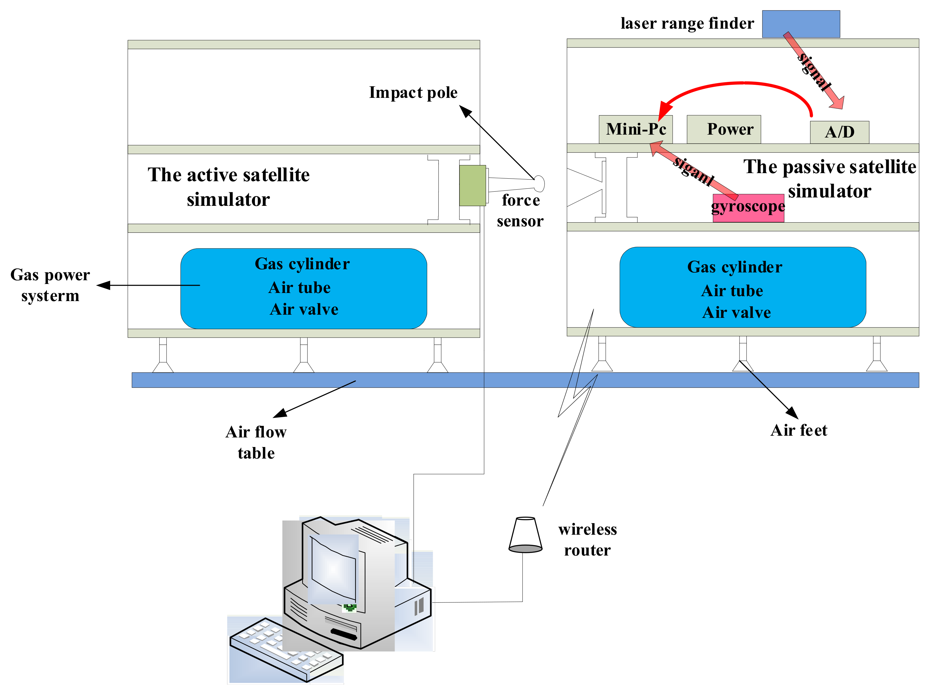
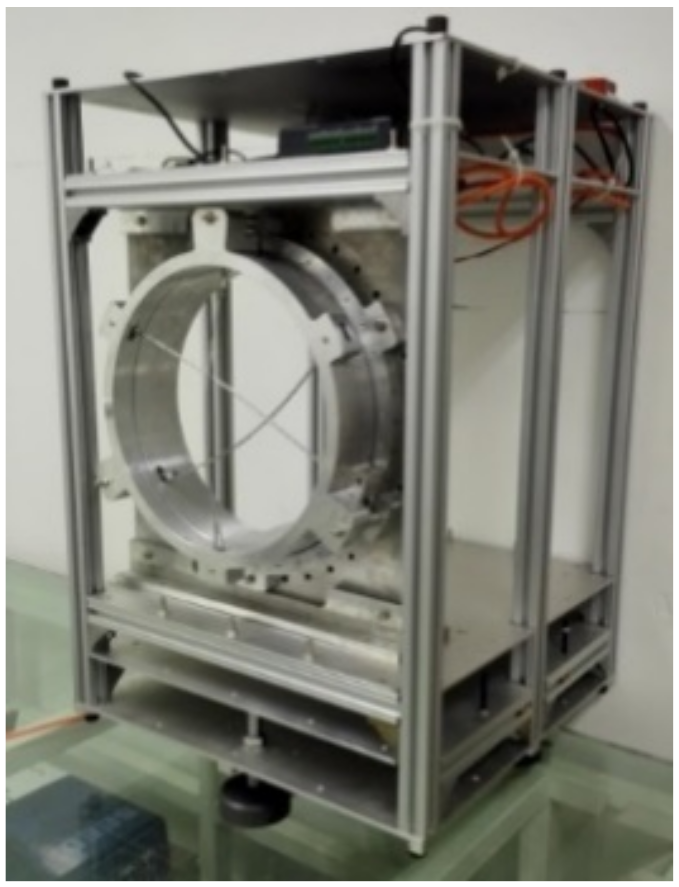
An experimental testbed on ground was constructed. It includes four parts: the air flow table, the active satellite simulator, the passive satellite simulator, and the collection system. The general scheme of this testbed, the two satellite simulators with the impact pole and cone installing are shown in Figure 11, Figure 12 and Figure 13, respectively. The air flow table was made of tempered glass, which was polished to reduce friction. The air bearings were NEW WAY S108001 air bearings with a diameter of 80 mm and working air pressure of 0.4 MPa. The air flow was supplied by two 5 L nitrogen gas bottles whose initial pressure was 30 MPa. The active satellite simulator was fixed to the air flow table, while the passive satellite simulator was able to move and be accelerated manually to simulate the randomness of the motion state of the target object in a space capture task.
By virtue of the gas power system, the satellite simulators could float on the air flow table. Therefore, the friction force was largely reduced. The DT50-P1113 laser range finder was used to measure the relative position of two satellite simulators. The measuring range of this laser range finder was 10 m with a measuring accuracy of ± 1   mm and a repeated accuracy is ± 2 . 5   mm . The linear velocity can then be derived by data processing software by calculating the first derivative of the change of relative position over time. The MTi gyroscope was used to measure the angle of the passive satellite simulator, and the ATI-Nano17 six-dimensional force sensor was used to measure impact force. The measuring range of the MTi gyroscope was 0 to 360 degrees clockwise and counterclockwise with a linear error of 0.1 degree and nonlinear error of 0.1% FS. The ATI-Nano17 force sensor was 0.907 kg in weight, 17 mm in diameter, and 15 mm in height, which is small and light. The maximum measurable axial load was ± 480   N and ± 1.8   Nm . The best resolution for this force sensor was 1/320 N and 1/64,000 Nm. This force sensor can measure six forces, which are along the positive and negative direction of the x, y, and z-axis of the Cartesian coordinate system. In this experiment, only the force along the impact direction is measured. The relative contact velocity and the impact force were derived and analyzed according to the experiment recorded data on the working PC.
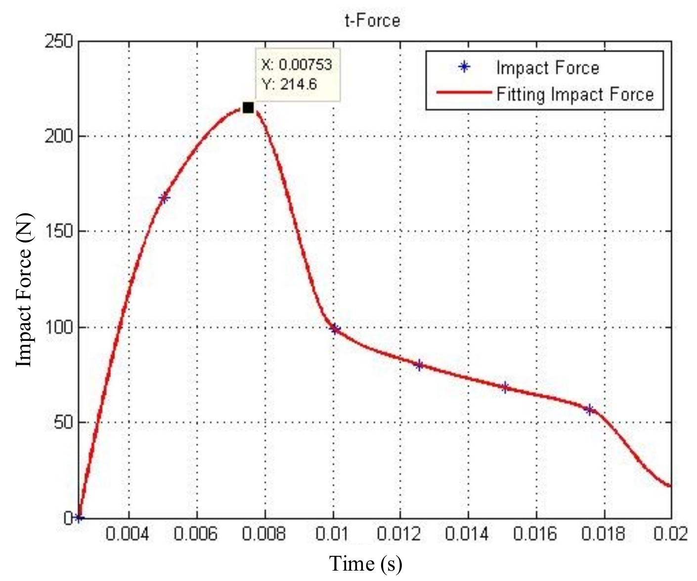
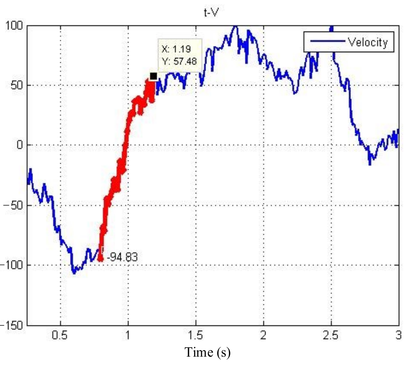
In Section 2, the impact dynamic model between the grapple shaft and the rigid body was set. To verify the validity of the model, impact experiments were carried out. The two simulators moved relative to another, and then the impact occurred between the impact pole and cone. Meanwhile, the relative displacement and impact force were recorded, which are shown in Figure 14 and Figure 15, respectively. The relative contact velocity was derived by the displacement, as shown in Figure 16.
From 0 s to 1 s, the two simulators move relative to another, so the relative displacement keeps decreasing until the impact occurs. After 1 s, the two simulators separate, then the displacement gets continuously increased. The red marked line in Figure 15 shows the relative velocity during the impact period. It is obvious that the relative contact velocity at the initial time and the detached time is v = 94.83   mm / s and v o u t = 57.48   mm / s , respectively. Figure 16 shows the actual impact force is F = 214.6   N .

4.1.2. Simulations

(1)
Simulations without considering friction
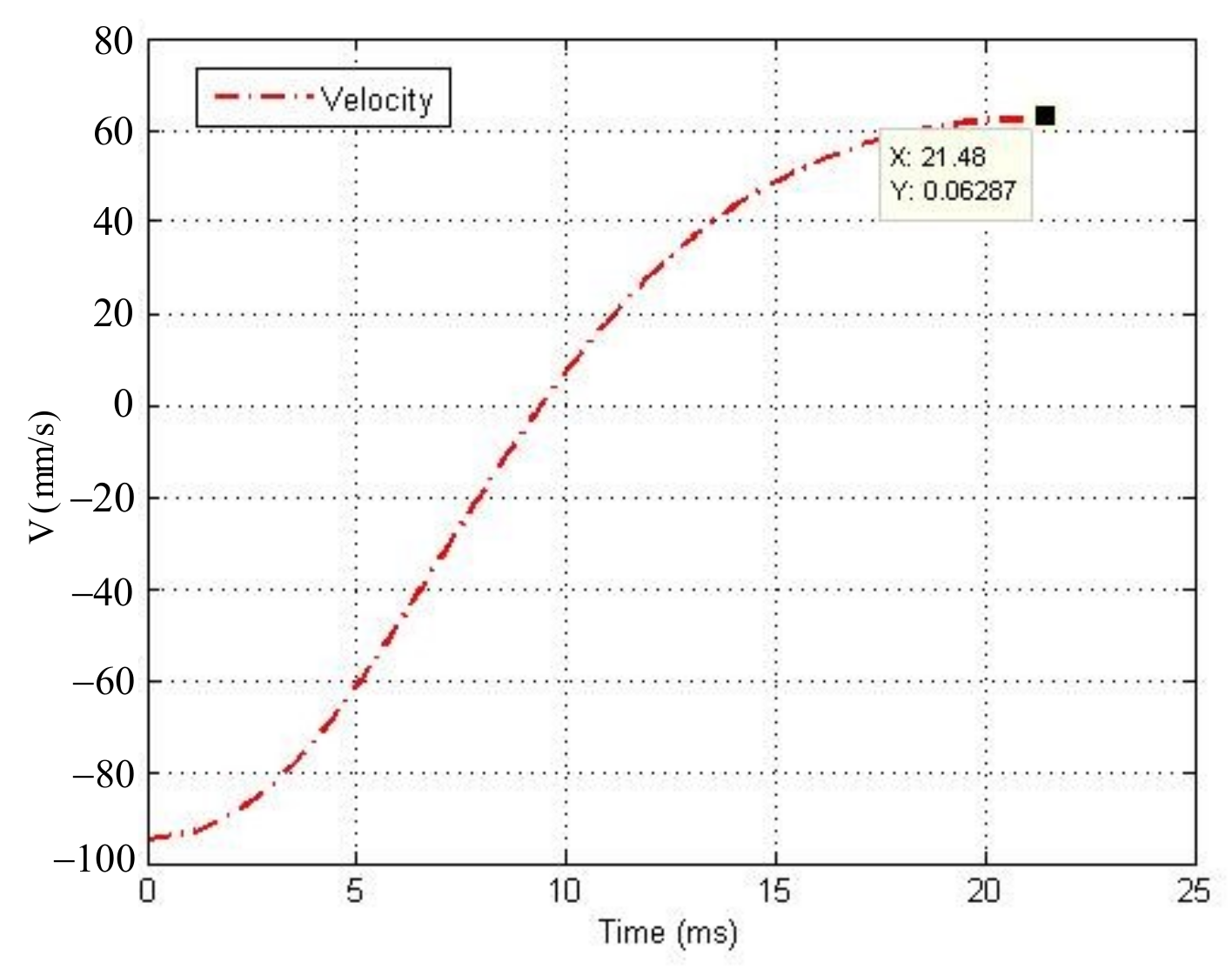
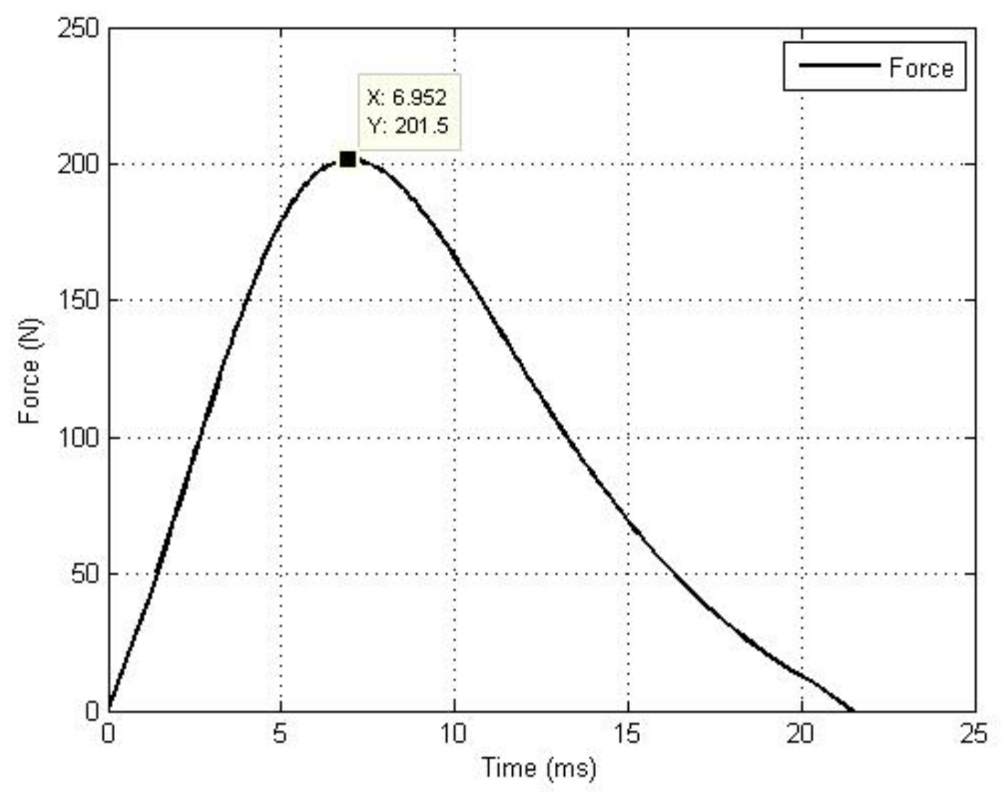
According to the impact dynamics above, a simulation based on MATLAB was run. The initial parameters (all the parameters were set according to the experimental testbed from Section 4.1) included: the mass of the two impact objects m 1 = 38.4   kg and m 2 = 21.85   kg , the initial relative contact velocity v = 94.83   mm / s , the contact planar radius r = 18   mm , and the restitution coefficient c = 0.55 . For the Zhiying–Qishao model, when the value of the restitution coefficient was between 0.5 and 0.6, the value of the input restitution coefficient was closest to that of the output restitution coefficient, meaning that the model had the highest accuracy in this interval [29]. It is reasonable to take the middle point of this interval as the value of the restitution coefficient c , which was c = 0.55 . Figure 17 and Figure 18 show the relative contact velocity and the impact force, respectively. At the detached time, the theoretical velocity of the two objects is v o u t = 62.87   mm / s , and the theoretical impact force is F = 201.5   N .
Comparing the theoretical data with the actual ones, we can get the relative contact velocity error and the impact force error as:
v e r r o r = v o u t v o u t v o u t × 100 % = 9.22 %
F e r r o r = F F F × 100 % = 6.1 %
To make the data more credible, we carried out several full experiments. All the data are shown in Table 1.
The data in Table 1 show that the average velocity error was v e r r o r = 12.64 % , and the average force error was F e r r o r = 9.25 % .
(2)
Simulations considering friction
(a)
The friction experiments
Although the satellite simulators float on the table, they still have some resistance. We speculated that the error in Section 3 was caused by the table friction. To verify the conjecture, we designed an experiment. The passive simulator got an initial velocity by applying an instantaneous force on it. As there was still a relatively small friction on the table, the satellite would stop itself.
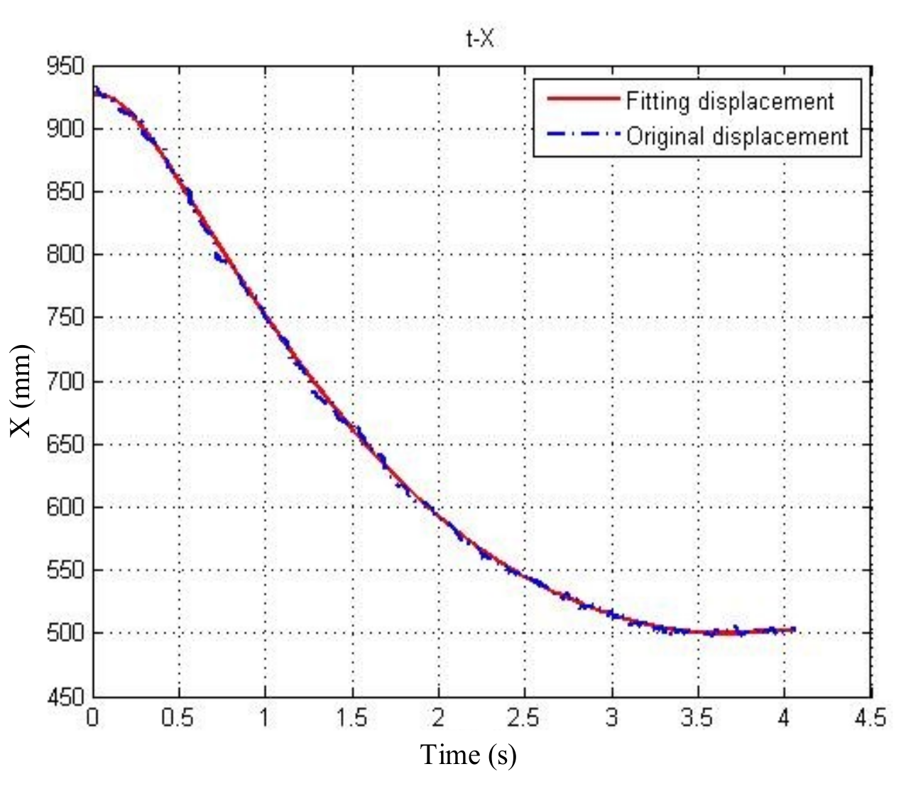
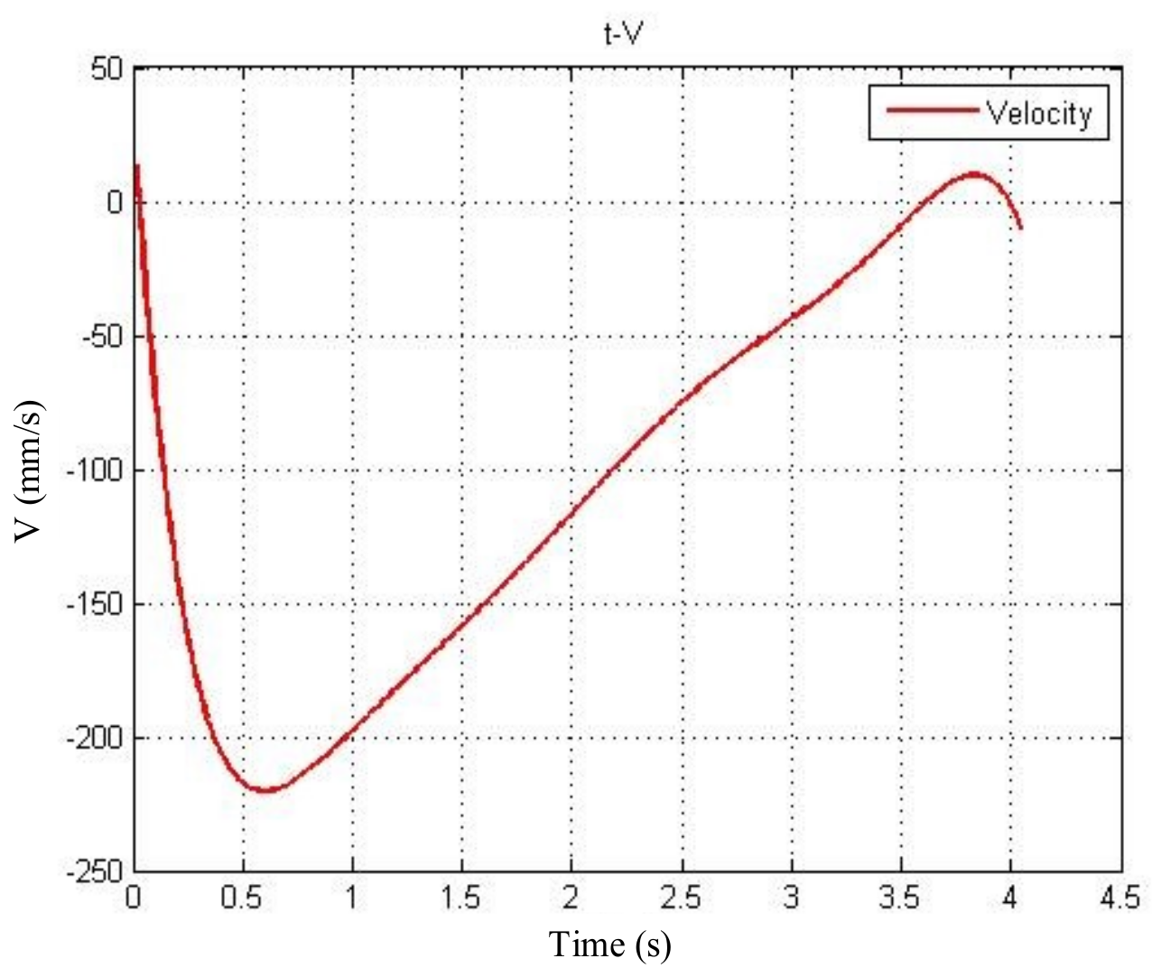
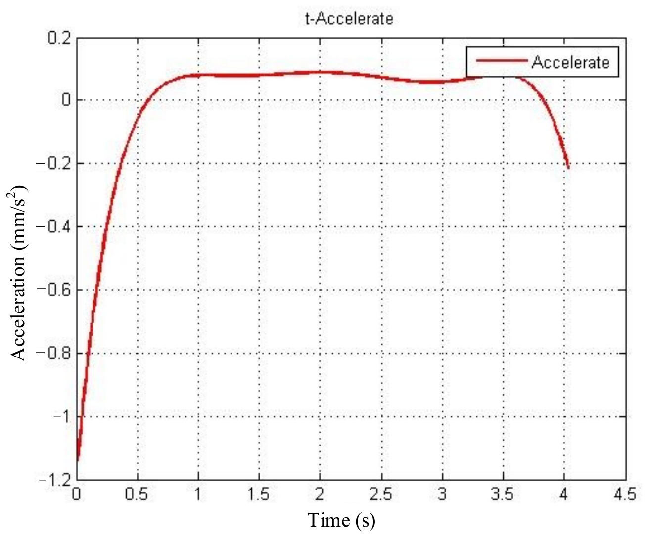
According to satellite kinematics and Newton’s second law, the friction factor can be derived. Figure 19 shows the displacement data of the satellite simulator from the first experiment. The original displacement is discrete point sets collected by the laser range finder. To derive smooth velocity and acceleration curves, the original displacement was fitted by a polynomial, and the red curve in Figure 19 represents the fitting result. Figure 20 shows the satellite simulator velocity, derivative of the fitting displacement. Furthermore, Figure 21 shows the acceleration of the satellite simulator. During the 0 s to 0.5 s period, the satellite simulator speeds up to the maximum velocity by thrust. Then, it moves freely on the table with only the table friction, and at 4.1 s, the satellite simulator stops.
We can see that the acceleration from 1 s to 3 s is a = 0.088   m / s 2 . As a result, the friction applied by the air flow table on the passive simulator is f 1 = m 1 a = 3.3792   N . In addition, according to the Coulomb’s friction law, the friction factor μ = f 1 / m 1 g = 0.0088 .
To make the data more credible, we performed six experiments in total. All the data are listed in Table 2.
Calculating the average acceleration in Table 2, the expected friction factor is μ = 0.00905 .
The mass of the active simulator is m 2 = 21.85   kg , so the total friction force during the impact is f = μ ( m 1 + m 2 ) g = 5.4526 N .
(b)
The impact dynamic model with friction
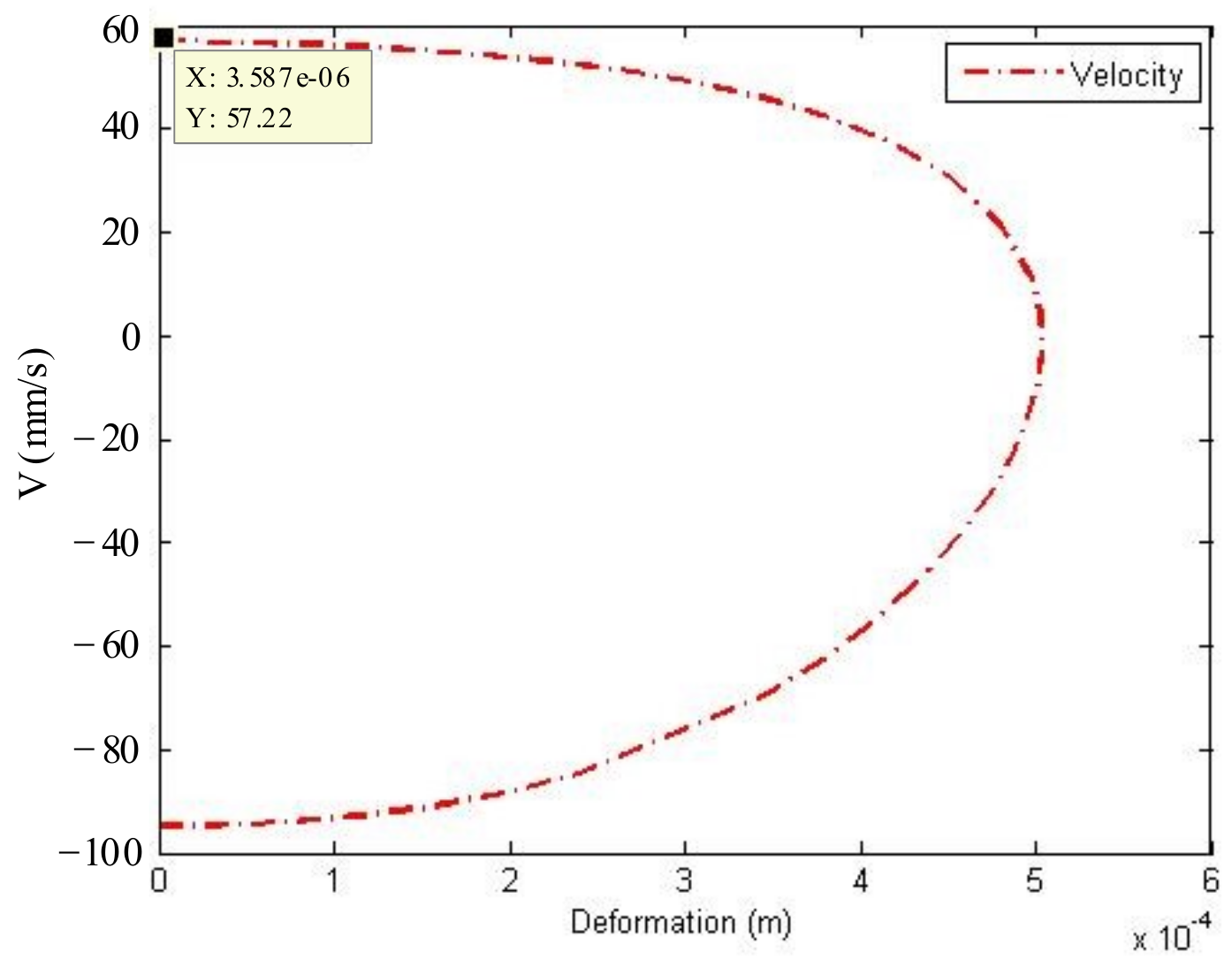
As differential equations of inseparable variables, Equation (11) is solved by the ode15s function in MATLAB. Using the same initial parameters as in Section 3.1, Figure 22 shows the relation between relative contact velocity and deformation. We can see that the relative contact velocity at detached time is v o u t _ f = 57.22   mm / s .
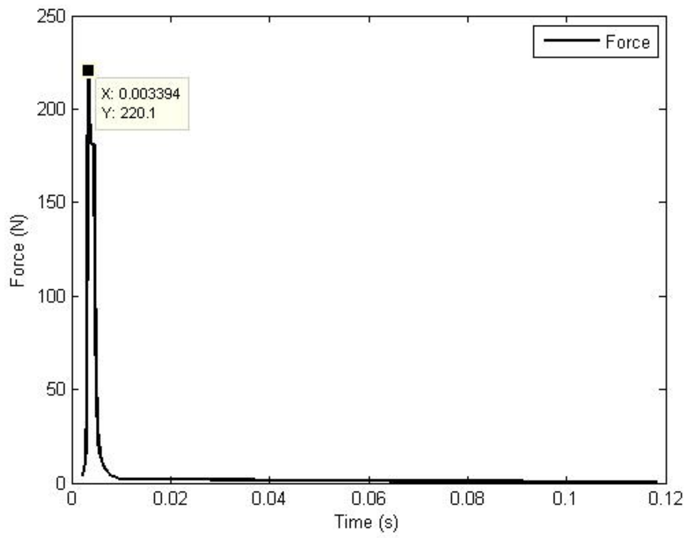
According to Equation (1), the impact force of every step can be calculated. In addition, based on the formula Δ t = Δ v / δ ¨ , the time interval between each step is obtained. Therefore, Figure 23 was plotted to show the relation between impact force and time. The maximum impact force during the period is F f = 220.1   N .
Introducing the initial velocity from Table 1 into the improved impact dynamic model, the output data were compared with the experimental ones as shown in Table 3.
According to the data from Table 3, the average velocity error is v e r r o r _ f = 5.59 % , and the average force error is F e r r o r _ f = 3.83 % . Compared with the results from Table 1, v e r r o r _ f = 5.59 % < v e r r o r = 12.64 % , F e r r o r _ f = 3.83 % < F e r r o r = 9.25 % . It is obvious that the improved impact dynamic model has advantages over the former, especially when the impact objects contact with the environment. These errors caused by the nonlinear model itself or the acquisition precision of the sensor are hard to avoid, so these errors are reasonable.
According to the above ground experiments and simulations, the impact dynamic model considering friction established in this paper is more accurate than that without taking friction into account. The value of the friction in this experiment was relatively high for air flow table experiments, and the upgraded impact dynamic model derived here is dedicated to microgravity simulators with a high friction

4.2. Experiments of the Impact Dynamic Model of a Flexible Body

We used the capture rod installed on the end of the manipulator and the flexible wire rope attached on the target star to carry out the impact experiments for a flexible body. The diameter of the flexible wire rope was 3 mm, the maximum load was 571 kg, the effective length was 0.30 m, the linear density was 0.0365 kg/m, and the initial total bending angle was 26 degrees. The flexible wire rope was divided into 30 sections, and the installation distance between the head and end was 0.26 m at the impact time. The target star structure with the space snare capture is shown in Figure 24, the physical figure is shown in Figure 25, and its dynamic parameters are shown in Table 4. The control variable method was used to evaluate the dynamic modeling accuracy of the contact impact between the target load and the flexible wire rope.
(1)
Contact at the same point with different contact velocity
We set the joint angle of the manipulator at the impact time as 0.8727 , 1.7453 , 0.8727 ( r a d ) , as shown in Figure 26.
First, the polynomial fitting method described in Section 3.2 was used to fit the relation between the compression and the impact force at the 16th node of the flexible wire rope. Since the installation distance between the head and the end was determined, the unitary polynomial was used to fit the compression, and the fitting result was as follows:
F c = 4 . 13 × 10 4 δ v 2 + 2089 δ v 8 . 79 × 10 4
where the coefficient of determination is close to 1 and the fitting accuracy is close to 100%.
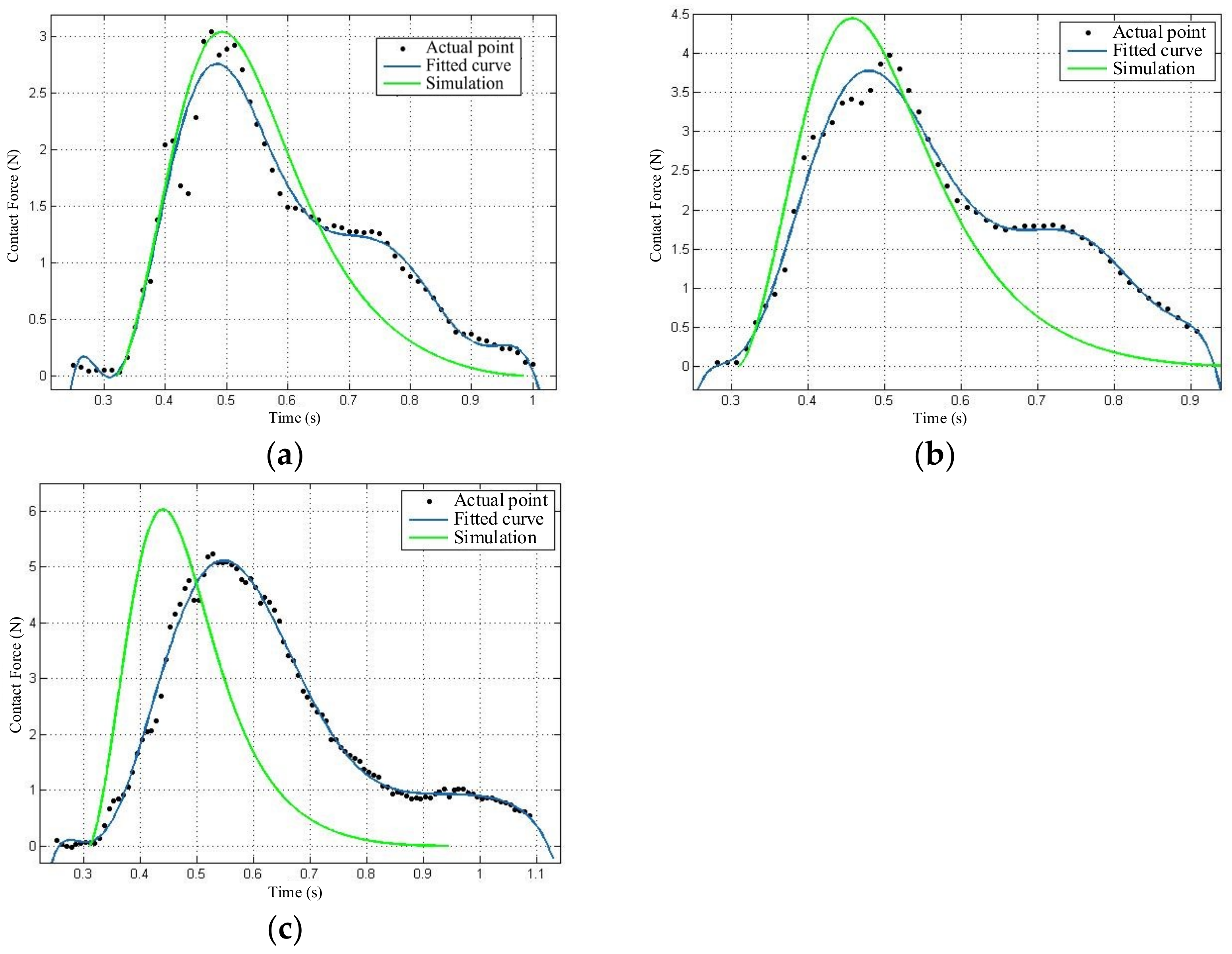
The actual impact force data between the end capture rod of the manipulator and the flexible wire rope were collected by the six-axis force sensor. According to the actual parameters, the initial value of the theoretical calculation was set. Based on the theory proposed in this paper, the contact stiffness coefficient of the flexible wire rope virtual spring was calculated by Equation (46), and the theoretical contact impact force was calculated by the Hertz damping model. It was compared to the actual impact force data. As shown in Figure 27, the three plots show that the capture rod of the end of the manipulator contacts the 16th nodes of the flexible wire rope at the relative speed of 0.06 m/s, 0.08 m/s, and 0.10 m/s, respectively. The black point represents the actual sampling value of the six-axis force sensor, the blue curve is the fitting curve of the actual impact force based on the sampling value, and the green curve is the theoretical contact curve based on the method proposed in this paper. The maximum values of the actual impact force are 2.76 N, 3.77 N, and 5.23 N, respectively. The peak value of the impact force increases with the increase of the relative contact velocity, which proves the theory of reducing the peak value of the impact force by reducing the relative contact velocity proposed in this paper.
It is worth noting that the peak value of the impact force and impact pulse are two major standards to analyze the effect of the impact force. The peak value of the impact force is the maximum impact force during the entire impact process. If this peak value is too large, the manipulator and the target object will be damaged or destroyed. The impact impulse is the accumulated effect of the impact force over the entire impact process. It is the accumulated effect over contact time. This impulse will cause a disturbance to the capturing process and the target load (mainly on posture and motion state), causing more difficulties for the capture task [33,34,35]. For the flexible capture, the capturing device has a strong tolerance on the motion state and posture of the target load. Thus, the disturbance caused by the impact impulse is not more significant than the potential structural damage or destruction caused by the peak value of the impact force in this case. As a result, this paper compares the peak value of the impact force in the following parts.
(2)
Contact at different points with the same speed
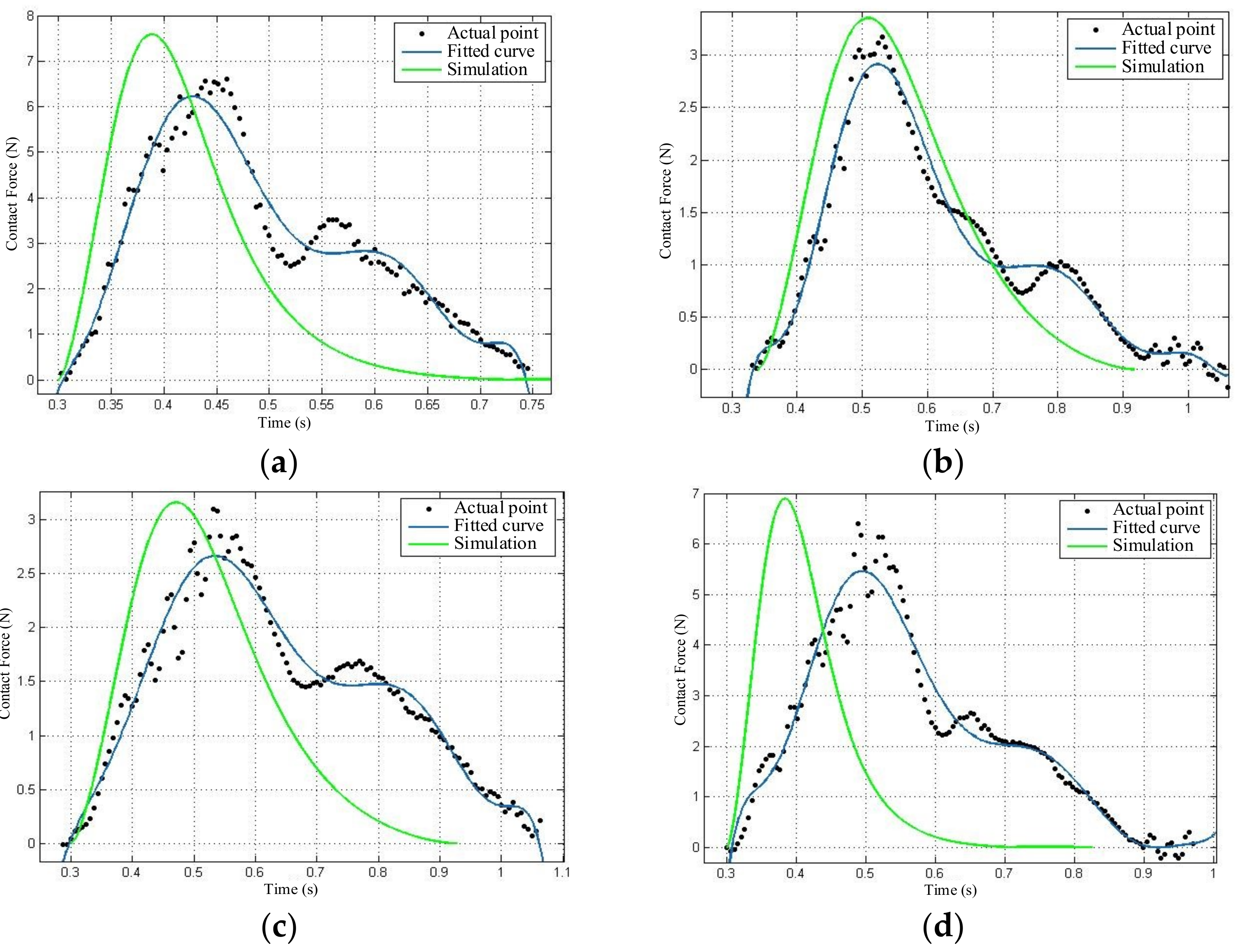
Let the capture rod at the end of the manipulator impact with the 5th, 10th, 20th, and 25th nodes on the flexible wire rope at the same contact speed of 0.06 m/s. The obtained impact force curve is shown in Figure 28. Under the same contact speed, the peak value of the impact force generated at the 5th and 25th nodes are relatively large, while that at the 10th and 20th nodes are relatively small. Among them, the maximum value is 6.22 N, and the minimum value is 2.66 N. The maximum value is approximately 2.4 times greater than the minimum value, which proves that the peak value of the impact force is larger when the flexible wire rope is close to the installation position, and the peak value of the impact force is smaller in the middle area.
(3)
Analysis of the experimental results
To calculate the accuracy of the theoretical model of the flexible wire rope proposed in this paper, the accuracy equation was established as follows:
ξ = 1 F p _ max F t _ max F t _ max × 100 %
where F p _ max , F t _ max are the peak values of the impact force obtained by actual data fitting and theoretical simulation, respectively.
Table 5 summarizes the repeated experiments. For the 5th, 10th, 20th, and 25th node on the flexible wire rope, positive impact occurs at the speed of 0.06 m/s, 0.08 m/s, and 0.10 m/s, respectively. Comparing the fitting curve of the six-axis force data sampling points with the theoretical simulation results, we can find that the maximum accuracy is 89.70%, the minimum is 73.18%, and the average accuracy of the model is 81.61%. To a certain extent, the impact force of the flexible wire rope is predictable. At the same time, the following common features can be seen from the above figures:
(1)
In general, the peak value of the impact force calculated by the theoretical simulation is larger than that of the numerical fitting curve of the six-axis force collected data.
(2)
The contact time between the end capture rod and the flexible wire rope of the actual manipulator is significantly longer than that of the theoretical simulation.
(3)
The fitting curve of the actual impact force sample points obviously fluctuates.
(4)
The theoretical simulation results show that the impact force reaches its peak quickly.

5. Conclusions

Impact dynamic models between two objects were established in this paper. For the capture task between a grapple shaft and a rigid body, its impact dynamic model considering friction factor was established based on the Zhiying–Qishao model. For the capture task with a flexible impact, an impact dynamic model between a grapple shaft and a flexible wire rope was established. The ground experiments and the simulations were carried out with two objects on an air flow table. For the impact of rigid bodies, the experiment results proved that the impact dynamic model considering friction was more accurate than those without taking friction into account. For the impact of flexible bodies, the ground experiments and simulations verified the effectiveness of the impact dynamic model. Finally, to a certain extent, the contact force of a flexible wire rope can be predicted with the impact dynamic model.

Author Contributions

Conceptualization, Y.C. (Yaxing Cai), Y.C. (Yujun Chen) and Y.L.; software and validation, Y.C. (Yaxing Cai) and X.W.; formal analysis, Y.C. (Yaxing Cai); resources, Y.C. (Yaxing Cai) and Y.C. (Yujun Chen); writing—original draft preparation, Y.C. (Yaxing Cai); writing—review and editing, Y.C. (Yujun Chen) and Y.L.; visualization, Y.C. (Yujun Chen) and Y.L.; supervision, X.W. All authors have read and agreed to the published version of the manuscript.

Funding

This research received no external funding.

Institutional Review Board Statement

Not applicable.

Informed Consent Statement

Not applicable.

Data Availability Statement

Not applicable.

Conflicts of Interest

The authors declare no conflict of interest.

References

  1. Akhloumadi, M.; Ivanov, D. Influence of Satellite Motion Control System Parameters on Performance of Space Debris Capturing. Aerospace 2020, 7, 160. [Google Scholar] [CrossRef]
  2. Wang, C.; Dong, Z.; Yin, H. Research Summarizing of On-orbit Capture Technology for Space Target. J. Acad. Equip. 2013, 24, 63–66. [Google Scholar]
  3. Deng, Z.; Li, L.; Li, B.; Wu, X. Comprehensive analysis and evaluation on performance of space grappling device. J. Mach. Des. 2012, 29, 1–6. [Google Scholar]
  4. Gibbs, G.; Sachdev, S. Canada and the international space station program: Overview and status. Acta Astronaut. 2002, 51, 591–600. [Google Scholar] [CrossRef]
  5. Matsueda, T.; Masahiro, A.; Eiji, S. Real-time simulator for JEM Remote Manipulator System (JEMRMS). Space Technol. Sci. 1992, 1, 1427–1430. [Google Scholar]
  6. Chen, G.; Wang, Y.; Wang, Y.; Liang, J.; Zhang, L.; Pan, G. Detumbling strategy based on friction control of dual-arm space robot for capturing tumbling target. Chin. J. Aeronaut. 2020, 33, 1093–1106. [Google Scholar] [CrossRef]
  7. Kostek, R.; Aleksandrowicz, P. Simulation of car collision with an impact block. In Proceedings of the IOP Conference, Pitesti, Romania, 8−10 November 2017; Volume 252, pp. 1–7. [Google Scholar]
  8. Xie, J.; Dong, M.; Li, S. Dynamic characteristics for the normal impact process of micro-particles with a flat surface. Aerosol Sci. Technol. 2018, 52, 222–233. [Google Scholar] [CrossRef] [Green Version]
  9. Taillon, G.; Miyagawa, K. Stochastic Impact Model: Poisson Processes and Copulas to Model Cavitation Erosion Impacts. Int. J. Fluid Mach. Syst. 2019, 12, 418–429. [Google Scholar] [CrossRef]
  10. Kim, S. Contact Dynamics and Force Control of Flexible Multi-Body Systems. Ph.D. Thesis, Department of Mechanical Engineering, McGill University, Montreal, QC, Canada, 1999. [Google Scholar]
  11. Reboucas, G.; Santos, I.; Thomsen, J. Validation of vibro-impact force models by numerical simulation, perturbation methods and experiments. J. Sound Vib. 2018, 413, 291–307. [Google Scholar] [CrossRef] [Green Version]
  12. Yousefpour, M.; Payvandy, P.; Ahmadi, M. Investigation of physical models accuracy optimized by PSO for determining low-velocity impact behavior of warp-knitted spacer fabrics. J. Text. Inst. 2018, 109, 312–321. [Google Scholar] [CrossRef]
  13. Roy, A.; Carretero, J.A. A damping term based on material properties for the volume-based contact dynamic model. Int. J. Non-Linear Mech. 2012, 47, 103–112. [Google Scholar] [CrossRef]
  14. Zhao, D.; Liu, Y.; Li, H. Modified Hertz-damp model for base-isolated structural pounding simulation under near-fault earthquakes. J. Vibroeng. 2017, 19, 1962–1979. [Google Scholar] [CrossRef]
  15. Xia, Y.; Yin, Y.; Chen, Z. Dynamic analysis for peg-in-hole assembly with contact deformation. Int. J. Adv. Manuf. Technol. 2006, 30, 118–128. [Google Scholar] [CrossRef]
  16. Liu, X.; Li, H.; Chen, Y. Dynamics and control of capture of a floating rigid body by a spacecraft robotic arm. Multibody Syst. Dyn. 2015, 33, 315–332. [Google Scholar] [CrossRef]
  17. Qiao, B.; Wu, X. A Model Order Reduction Method for Impact-contact Dynamics Simulation of Flexible Space Robotic Manipulator. J. Sichuan Univ. 2012, 44, 214–220. [Google Scholar]
  18. Kosenko, I.; Aleksandrov, E. Volumetric modification of the Hertz contact problem and its application to the multibody dynamics simulation. J. Mech. Sci. Technol. 2009, 23, 931–937. [Google Scholar] [CrossRef]
  19. Hunt, K.; Crossley, F. Coefficient of restitution interpreted as damping in vibroimpact. J. Appl. Mech. 1975, 42, 440–445. [Google Scholar] [CrossRef]
  20. Gonthier, Y.; McPhee, J.; Lange, C.; Piedboeuf, J. Piedboeuf, A regularized contact model with asymmetric damping and dwell-time dependent friction. Multibody Syst. Dyn. 2004, 11, 209–233. [Google Scholar] [CrossRef]
  21. Qin, Z.; Lu, Q. Analysis of impact process based on restitution coefficien. J. Dyn. Control 2006, 4, 294–298. [Google Scholar]
  22. Russell, J.; Anderson, W. Equilibrium and stability of a circularly towed cable subject to aerodynamic drag. J. Aircr. 1977, 14, 680–686. [Google Scholar] [CrossRef]
  23. Carter, J.; Greene, M. Deployment and retrieval simulation of a single tether satellite system. In Proceedings of the Twentieth Southeastern Symposium on System Theory, Charlotte, NC, USA, 20−22 March 1988; pp. 657–660. [Google Scholar]
  24. Tan, Y.; Liu, Y.; Liu, H.; Hengao, E. Modeling and capture dynamics of flexible cables used in large-scale space end-effector. Robot 2011, 33, 156–160. [Google Scholar] [CrossRef]
  25. Pan, D.; Wei, C.; Tian, H.; Zhang, Y. Capturing Dynamics and Experiment of the Space Large End Effector. J. Astronaut. 2014, 35, 1120–1126. [Google Scholar]
  26. Bergou, M.; Wardetzky, M.; Robinson, S.; Audoly, B.; Grinspun, E. Discrete elastic rods. ACM Trans. Graph. 2008, 27, 15–19. [Google Scholar] [CrossRef]
  27. Ma, L.; Xie, S.; Liu, P.; Ma, L.-Y. Modeling and Progression Simulation of Flexible Cables Based on Mass-Spring System. J. Syst. Simul. 2014, 26, 733–738. [Google Scholar]
  28. Uyama, N.; Yoshida, K.; Nakanishi, H.; Oda, M.; Sawada, H.; Suzuki, S. Contact Dynamic modeling for Snare Wire Type of End Effector in Capture Operation. Trans. Jpn. Soc. Aeronaut. Space Sci. Aerosp. Technol. Jpn. 2012, 10, 77–84. [Google Scholar] [CrossRef] [Green Version]
  29. Spong, M.; Hutchinson, S.; Vidyasagar, M. Robot Dynamics and Control, 2nd ed.; John Wiley & Sons: New Jersey, NY, USA, 2004; pp. 99–109. [Google Scholar]
  30. Zhang, X.; Xu, S.; Jia, C.; Wang, G.; Chu, M. Generalized Modeling of Soft-Capture Manipulator with Novel Soft-Contact Joints. Energies 2020, 13, 1530. [Google Scholar] [CrossRef] [Green Version]
  31. Kuroda, S.; Higuchi, T.; Tsujimoto, Y.; Ueno, S. Capturing simulation of space debris with super multi-link space manipulator. In Proceedings of the 2016 55th Annual Conference of the Society of Instrument and Control Engineers of Japan (SICE), Tsukuba, Japan, 20−23 September 2016; pp. 660–666. [Google Scholar] [CrossRef]
  32. Hong, X. The Collision Dynamics Analysis of Space Flexible Manipulator with Performing On-Orbit Capture Task. Ph.D. Thesis, Beijing University of Post and Telecommunication, Beijing, China, 2017. [Google Scholar]
  33. Yoshida, K.; Sashida, N. Modeling of impact dynamics and impulse minimization for space robots. In Proceedings of the 1993 IEEE/RSJ International Conference on Intelligent Robots and Systems, Yokohama, Japan, 26−30 July 1993; Volume 3, pp. 2064–2069. [Google Scholar] [CrossRef]
  34. Lin, Z.C.; Patel, R.V.; Balafoutis, C.A. Impact reduction for redundant manipulators using augmented impedance control. J. Robot. Syst. 1995, 12, 301–313. [Google Scholar] [CrossRef]
  35. Huang, P.F.; Yuan, J.P.; Xu, Y.S. Approach Trajectory Planning of Space Robot for Impact Minimization. In Proceedings of the 2006 IEEE International Conference on Information Acquisition, Weihai, China, 20−23 August 2006; pp. 382–387. [Google Scholar] [CrossRef]
Figure 1. The space snare capture.
Aerospace 08 00381 g001
Figure 2. The discrete model of the flexible wire rope.
Aerospace 08 00381 g002
Figure 3. The coordinate system of the flexible wire rope.
Aerospace 08 00381 g003
Figure 4. Force analysis on nodes B i , B i + 1 .
Aerospace 08 00381 g004
Figure 5. The initial position of the flexible wire rope.
Aerospace 08 00381 g005
Figure 6. The stress analysis of the flexible wire rope at initial state.
Aerospace 08 00381 g006
Figure 7. Determination of the distance range between the beginning and end of the flexible wire rope.
Aerospace 08 00381 g007
Figure 8. Virtual spring impact model of the flexible wire rope.
Aerospace 08 00381 g008
Figure 9. Force analysis of the flexible wire rope (including impact force).
Aerospace 08 00381 g009
Figure 10. Fitting process of contact stiffness coefficient of the flexible wire rope.
Aerospace 08 00381 g010
Figure 11. The general scheme of the ground experimental testbed.
Aerospace 08 00381 g011
Figure 12. The passive satellite simulator.
Aerospace 08 00381 g012
Figure 13. The active satellite simulator.
Aerospace 08 00381 g013
Figure 14. Relative displacement.
Aerospace 08 00381 g014
Figure 15. Impact force during the impact period.
Aerospace 08 00381 g015
Figure 16. Relative contact velocity.
Aerospace 08 00381 g016
Figure 17. Relative contact velocity.
Aerospace 08 00381 g017
Figure 18. Impact force.
Aerospace 08 00381 g018
Figure 19. The simulator displacement.
Aerospace 08 00381 g019
Figure 20. The simulator velocity.
Aerospace 08 00381 g020
Figure 21. The simulator acceleration.
Aerospace 08 00381 g021
Figure 22. The relative contact velocity.
Aerospace 08 00381 g022
Figure 23. Impact force.
Aerospace 08 00381 g023
Figure 24. The star target structure.
Aerospace 08 00381 g024
Figure 25. Physical map of target satellite.
Aerospace 08 00381 g025
Figure 26. Capture configuration of the manipulator. (a) The 3D simulation drawing and (b) physical map.
Aerospace 08 00381 g026
Figure 27. Contact with the flexible wire rope at the same point at different speeds. Relative speed: (a) 0.06 m/s, (b) 0.08 m/s, (c) 0.1 m/s.
Aerospace 08 00381 g027
Figure 28. Contact with the flexible wire rope at different points with the same speed. (a) Impact with the 5th node, (b) impact with the 10th node, (c) impact with the 20th node, (d) impact with the 25th node.
Aerospace 08 00381 g028
Table 1. The comparison between theoretical and experimental results.
Physical Data1st2nd3rd4th5th6th
Initial velocity v (mm/s)−94.83−124.5−81.2−204.2−173.8−101.6
Theoretical detached Velocity v o u t (mm/s)62.5782.5453.83135.4115.267.36
Actual detached velocity v o u t (mm/s)57.4872.2146.28122.4100.860.6
Velocity error v e r r o r (%)9.2214.316.310.614.2811.15
Theoretical impact force F (N)201.5279.4167.3505.8416.9218.9
Actual impact force F (N)214.6300.2195.4468.2450.8250.4
Force error F e r r o r (%)6.16.9214.388.037.5212.57
Table 2. The data of friction experiment.
Physical Data1st2nd3rd4th5th6th
a ( m / s 2 )0.0880.0890.0950.0920.090.089
Table 3. The comparison between improved theoretical result and experimental ones.
Physical Data1st2nd3rd4th5th6th
Initial velocity v (mm/s)−94.83−124.5−81.2−204.2−173.8−101.6
Theoretical detached Velocity v o u t _ f (mm/s)57.2279.2147.22131.8107.564.41
Actual detached velocity v o u t (mm/s)57.4872.2146.28122.4100.860.6
Velocity error v e r r o r _ f (%)0.459.692.037.687.426.29
Theoretical impact force F f (N)220.1286.8185.5463.3425.8240.2
Actual impact force F (N)214.6300.2195.4468.2450.8250.4
Force error F e r r o r _ f (%)2.84.465.11.075.543.99
Table 4. The dynamic parameters of the star target.
Mass (kg)Centroid (m)
41.7−0.0409310.001370.342138
Rotational inertia (kg·m2)
I x x I y y I z z I x y I y z I z x
3.407663.154771.614160.003530.02253−0.08852
Table 5. Accuracy of impact force model for the flexible wire rope.
Speed5th Node10th Node16th Node20th Node25th Node
0.06 m/s78.15%84.83%89.70%81.29%73.68%
0.08 m/s73.18%83.81%81.78%89.68%82.89%
0.10 m/s76.81%81.47%84.70%85.27%76.88%
Publisher’s Note: MDPI stays neutral with regard to jurisdictional claims in published maps and institutional affiliations.