Article

Development of a 6-DOF Testing Platform for Multirotor Flying Vehicles with Suspended Loads

Department of Mechanical Engineering, College of Engineering, Qassim University, P.O. Box 6677, Buraydah 51452, Qassim, Saudi Arabia
*
Author to whom correspondence should be addressed.
Aerospace 2021, 8(11), 355; https://doi.org/10.3390/aerospace8110355
Submission received: 2 September 2021 / Revised: 11 November 2021 / Accepted: 17 November 2021 / Published: 20 November 2021
(This article belongs to the Section Aeronautics)

Abstract

:
The development of multirotor vehicles can often be a dangerous and costly undertaking due to the possibility of crashes resulting from faulty controllers. The matter of safety in such activities has primarily been addressed through the use of testbeds. However, testbeds for testing multirotor vehicles with suspended loads have previously not been reported. In this study, a simple yet novel testing platform was designed and built to aid in testing and evaluating the performances of multirotor flying vehicles, including vehicles with suspended loads. The platform allows the flying vehicle to move with all six degrees of freedom (DOF). Single or three-DOF motions can also be performed. Moreover, the platform was designed to enable the determination of the mass properties (center of mass and moments of inertia) of small multirotor vehicles (which are usually required in the development of new control systems). The applicability of the test platform for the in-flight performance testing of a multirotor vehicle was successfully demonstrated using a Holybro X500 quadcopter with a suspended load. The test platform was also successfully used to determine the mass properties of the vehicle.

1. Introduction

In recent years, multirotor flying vehicles such as quadrotors have gained considerable popularity due to a variety of advantages that they possess, including reliability, simplicity, economy (cheap and easy to manufacture), and agility, among others. This has allowed them to find diverse uses in both civilian and military applications, such as in agriculture, search and rescue missions, reconnaissance missions, inspection (pipeline, risk zone inspections), and aerial mapping. Studies have thus continued to strive to advance this technology.
The development of a multirotor vehicle can be complex, time-consuming [1], and dangerous [2]. A typical development process for a multirotor vehicle usually involves modeling, system design, design of the vehicle controller, simulation, and actual flight testing of the vehicle [1,2,3]. During the development process, the simulation phase is important, as it can be used to ascertain whether the controllers are functioning correctly. This reduces the risk of dangerous and costly crashes (resulting from faulty controllers). It thus provides a safe and cheaper way for testing controller performance. While simulations serve an important role in the development process, it is known that the performance of the controllers in simulations differs from that in real flight [1]. This can be due to a variety of reasons, including the inability to completely simulate all flight conditions correctly and the likely existence of errors in any simulation. A solution to this problem is to perform flight tests in a testbed, which is a safe way to test the controllers in more realistic conditions. Most of the published articles in regard to multirotor testbed are related to hardware in the loop (HIL) flight tests. These tests are, however, not considered to be real flight tests, as the sensors that provide the vehicle states are not real [2,4,5,6].
A number of published works have addressed the matter of multirotor testing beds. In [7,8], the authors reported the development of one-axis test platforms that have been used for control testing, including tuning of the PID controllers. Since these testing platforms enable rotation about a single axis and no translations, they possess limited functionality. Testbeds inspired by the design of the gyroscope have been reported in [9,10,11,12,13,14,15]. These testbeds include 3-DOF designs in [9,10,11,12] that allow for rotation about the pitch, roll, and yaw axes; and 4-DOF designs with the additional DOF of elevation [13,14,15]. Six-DOF testbeds for control tests have been developed, such as those documented in [1,3,16,17,18]. These test beds allow for motion similar to motion in free flight, within some test limits, to avoid crashes. Additional information on these test beds is summarized in Table 1.
The test beds reported in [1,3,7,8,9,10,11,12,13,14,15,16,17,18] have been used for the safe (prevention of crashes and damage and loss to property) development of multirotor vehicles. These testbeds were designed for testing vehicles without attached suspended loads. Vehicles with suspended loads have numerous important applications, such as load delivery, mine detection, and rescue missions. However, the suspended load under such a vehicle creates pendulous motions that have an adverse effect on the performance of the vehicle. These motions need to be damped, and there are a variety of techniques to achieve this. One such method (of interest to this work) is an indirect control approach through cable angle feedback on the load motion to the multirotor vehicle. This technique, generally referred to as cable angle feedback (CAF) control, was pioneered by [19,20,21,22] and has since been used by numerous researchers; see [23,24,25,26]. A search in the literature for test platforms designed for testing vehicles these types of vehicles (vehicles with attached suspended loads) yielded no results. An alternative solution reported in the literature [27,28,29,30] is unrestricted flight (free flight) tests for testing vehicles with suspended loads. These tests included tests for multivehicle collaborative swing load transportation [29], anti-swing controllers [27,30], and swing load trajectory tracking [28] (see Table 1 for summarized details of these tests). While these tests were reported to be successful, there still remained a risk of crashing due to a variety of reasons, such as faulty controllers. There thus appears to be a gap in the literature for testbeds for testing multirotor vehicles with suspended loads. The work in this article sought to address this gap through the development of a testbed for multirotor vehicles with suspended loads. The proposed test platform is expected to help designers to test and optimize new controllers for multirotor flight vehicles in a safe environment. The proposed testbed has good mobility; therefore, it can be used to conduct both indoor and outdoor flight tests. The testbed was also designed to aid in the determination of physical parameters, including the center of mass along the yaw axis, and the moments of inertia about the pitch, yaw, and roll axes, which are usually required in the development of new multirotor vehicles.
Table 1. Information on testbeds for multirotor flying vehicles reported in the literature.
Number of Degrees of Freedom of the TestbedsSummarized Details of the TestbedType of
Vehicle in the Test
ReferenceSuspended Load
One DOFSingle axis test-bench used for PID controller tuningQuadcopter[7]No Suspended load
Single axis control test bench[8]
Three DOFGyroscopic test bench to test for stability tests including over or under actuated UACs as we control loop structuresQuadcopter[9]
Simple test rig for testing the designed controller. Rotation about two of the three axes (pitch, raw and yaw) is fixed allowing for rotation on only either the pitch or the roll. Translation is also fixed in all direction except for vertical movement which is also fixable.[10]
Gyroscopic 3 DOF test bench for analyzing control systems[11]
3DOF test bench to test for modified PID controller for stabilization of a quadcopter. The bed allows for rotation about three axes with translation being restricted.[12]
Four DOFTest platform based on gyroscope motion with 3 side circles. Tuning of control parameters. Four axis motion tests including, elevation, pitch, yaw and roll tests.Multi-rotor UAV[13]
3DOF test platform where rotation about all axes is allowed whereas translation is restricted, and a 1 DOF test platform complementing the first platformQuadcopter[14]
Development of a variable DOF flight control system for a quadcopter.Separate test for pitch, yaw roll and elevation through use of lockable universal joints and roller bearings allowing of up to 4 DOF.[15]
Six DOFTest bed to safely test designed UAV. Test platform allows for rotation about the pitch and roll axes and translation along three axes through linear guides.Quadcopter[16]
Test platform to test a developed hovering algorithm[17]
Testbed designed to evaluate performance of bother attitude and position controllers for multicopter vehicles. Testbed designed to allow 6DOF motion of the multicopter[1]
6 DOF test platform to emulate actual free flight to aid in the design and control of UAVs. In the platform the UAV is attached to the end effector of an articulated manipulator[18]
Quadcopter test bench for 6 DOF flight controller testing. Utilizes a 6 axes torque-force sensor to simulate the position of the vehicle[3]
Unrestricted free flightImplementation of an anti-swing controller on a quadcopter with a suspended load. Test conducted indoor in a cageQuadcopter[27]Suspended load
Proposed trajectory tracking controller for a single load carrying quadcopter. Experiments conducted indoor in a cage[28]
Development of a collaborative control and transportation of a swing load using multiple multicopters. Experiments conducted indoor[29]
Test of controller for a quadcopter with suspended load through window. Test conducted using Astec Hummingbird quadcopter to validate proposed control. Actual test with no testbed[30]

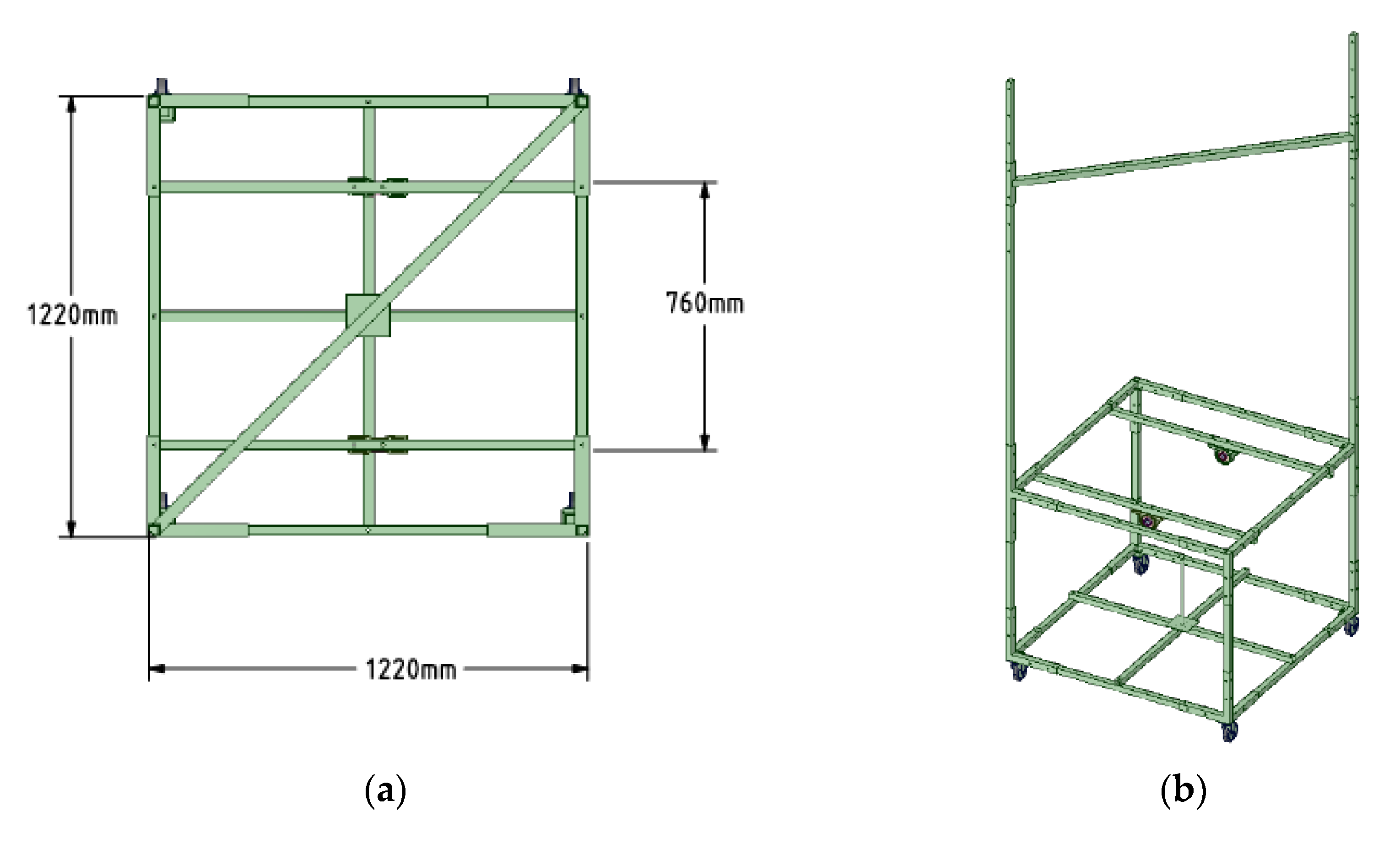
2. Proposed Test Platform

As previously mentioned, the development of a multirotor vehicle typically involves four phases: system design, controller design, simulations, and actual flight testing. In this work, a simple and cost-effective test platform is proposed to aid in the development of multirotor vehicles. The test platform was developed to enable indoor and outdoor flight tests of small multirotor vehicles (with mass ranging from 0.5 to 4 kg). The proposed test bed was also developed to aid in the determination of physical parameters which are required for the modeling of vehicle dynamics and simulation phases. These parameters include the vehicles center of mass (COM) along the yaw axis of the multirotor vehicle, and moments of inertia MOI about the pitch, roll, and yaw axes. What follows are descriptions of the various aspects and uses of the proposed test platform.

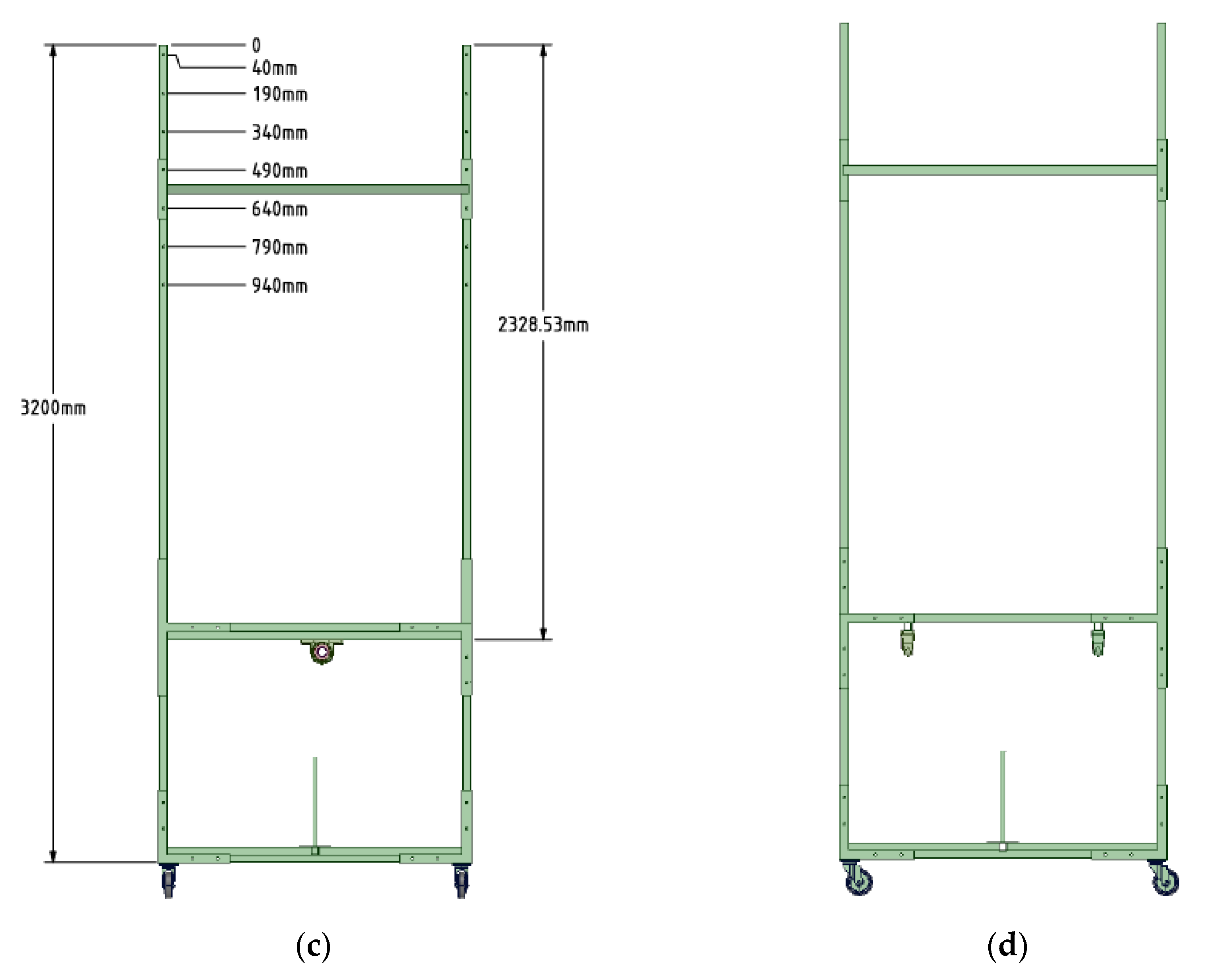
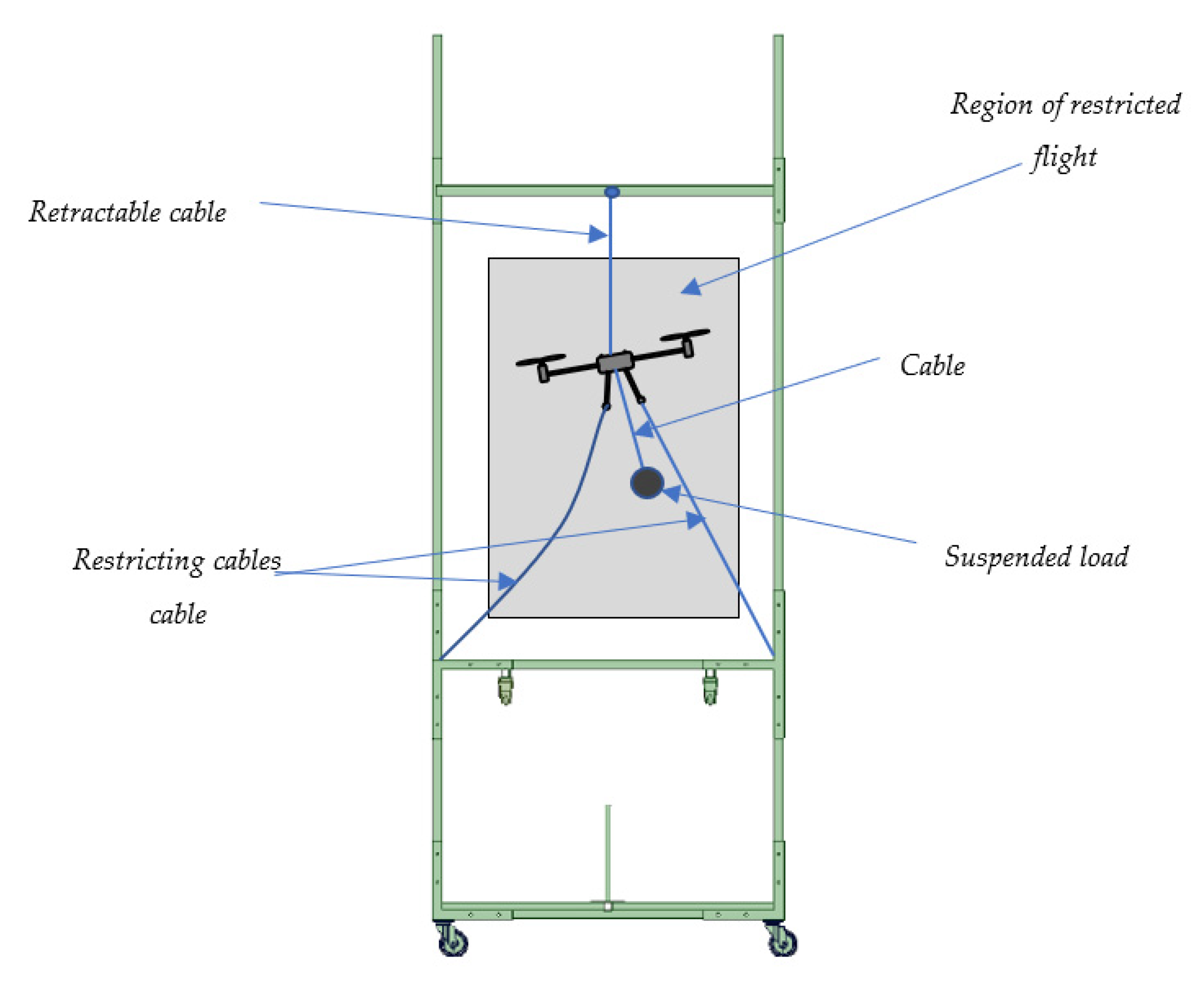
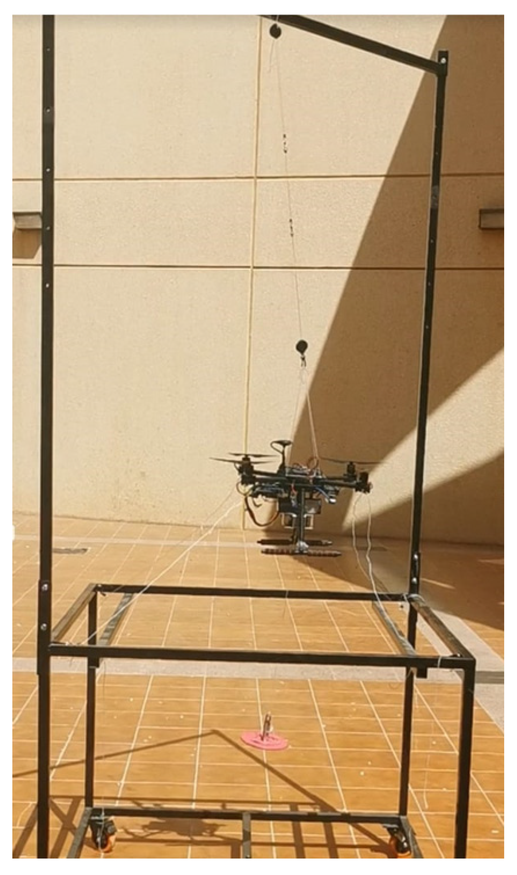
2.1. Restricted Flight Testing for Indoor and Outdoor Controller Evaluation

The test platform was developed to enable the evaluation of controllers (and more specifically, controllers for vehicles with attached suspended loads) for small multirotor vehicles. The idea is to constrain a vehicle in such a manner that would allow it to fly freely within a defined space. This would provide for a way to evaluate the vehicle’s controller(s) in a safe manner which would otherwise be costly or (and) dangerous in the event of defects. The CAD model of the proposed test platform is shown in Figure 1, which includes three views (top, side, and front) and the isometric view.
In a typical test, the multirotor would be restricted using cables and confined to fly within a specific region. The type and size of the multirotor will determine how the multirotor is restricted on the test platform. This would also dictate the volume of the region within which the test flight would be restricted. A depiction of the region to which flight is confined is shown in Figure 2. In this particular setup, the multirotor is restricted by cables attached to the arms or the landing gear. The cables’ lengths are chosen to allow the multirotor to make limited vertical movements and limited pitch, yaw, and roll maneuvers without coming into contact with the test platform structure or the cables getting entangled. The multirotor is also attached to a retractable cable (from the top, as shown in Figure 2) to provide guidance in the vertical direction and to stop the vehicle from dropping to the ground in an emergency.

Indoor Flight Testing

Anti-swing controllers require information on the position of the multirotor and the swing load (via cable angle feedback). For outdoor applications, GPS can be used to determine the position of vehicle. However, in indoor tests (which is usually the case in the development stage), GPS signals are unreliable and in some case undetectable. Thus, another position sensor must be used. There are a variety of techniques that can be used to obtain the vehicle position data indoors. These include visual odometer systems that are based on images taken by a camera, such as the realsense T265 tracking camera, or an ultrasonic device, such as the beacons system [31]. In this work, the T265 was adopted. This camera should be connected to a companion computer to provide the vehicle’s position. The companion computer used in this work was the NVIDIA Jetson Nano Developer Embedded Development Board A57 depicted in Figure 3. A detailed procedure to configure the camera with the companion computer and the necessary software packages is given in [32].
The position of the suspended load, for both indoor and outdoor tests, can be extracted from knowledge of the swing angles and the specified cable length of the suspended load. The swing angles ɸL and ɵL, as described in Figure 4, need to be determined in real-time. Various methods have been employed, including the use of encoders or potentiometers mounted in a gimbal that is attached to the suspension cable [33], the use of joystick sensors (see [34]), the use of a camera and image processing [35,36], and the use of a VICOM motion capture system [37,38]. In this work the joystick sensor approach was utilized.

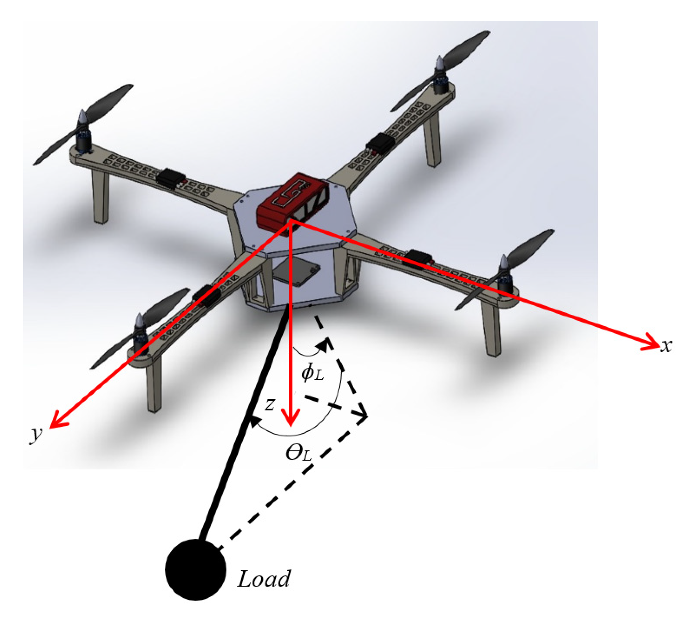
2.2. Test Setup for the Anti-Swing Controller’s Evaluation

The proposed test platform was used in the development of an anti-swing controller for a Holybro X500 quadrotor equipped with a Pixhawk controller. A suspended load was also attached to the quadcopter. To determine the position of the quadcopter during outdoor tests, a high precision real kinetic kinematics (RTK) GPS (with accuracy of up to 2 cm [39]) was fitted to the quadcopter. For indoor tests, the Realsense camera (with under 1% closed loop drift [40]) and Jetson nano A57 companion were fitted to the quadcopter. The camera was connected to the Jetson board through a USB cable, and the Jetson board was connected to the pixhawk through the telemetry cable, as shown in Figure 5. The swing angles were measured by a FrSky M9 Hall Sensor Gimbal joystick with a sensitivity of 2.5 mV/G [34]. Figure 6 shows an image of the Holybro X500 quadrotor ready for indoor and outdoor testing.

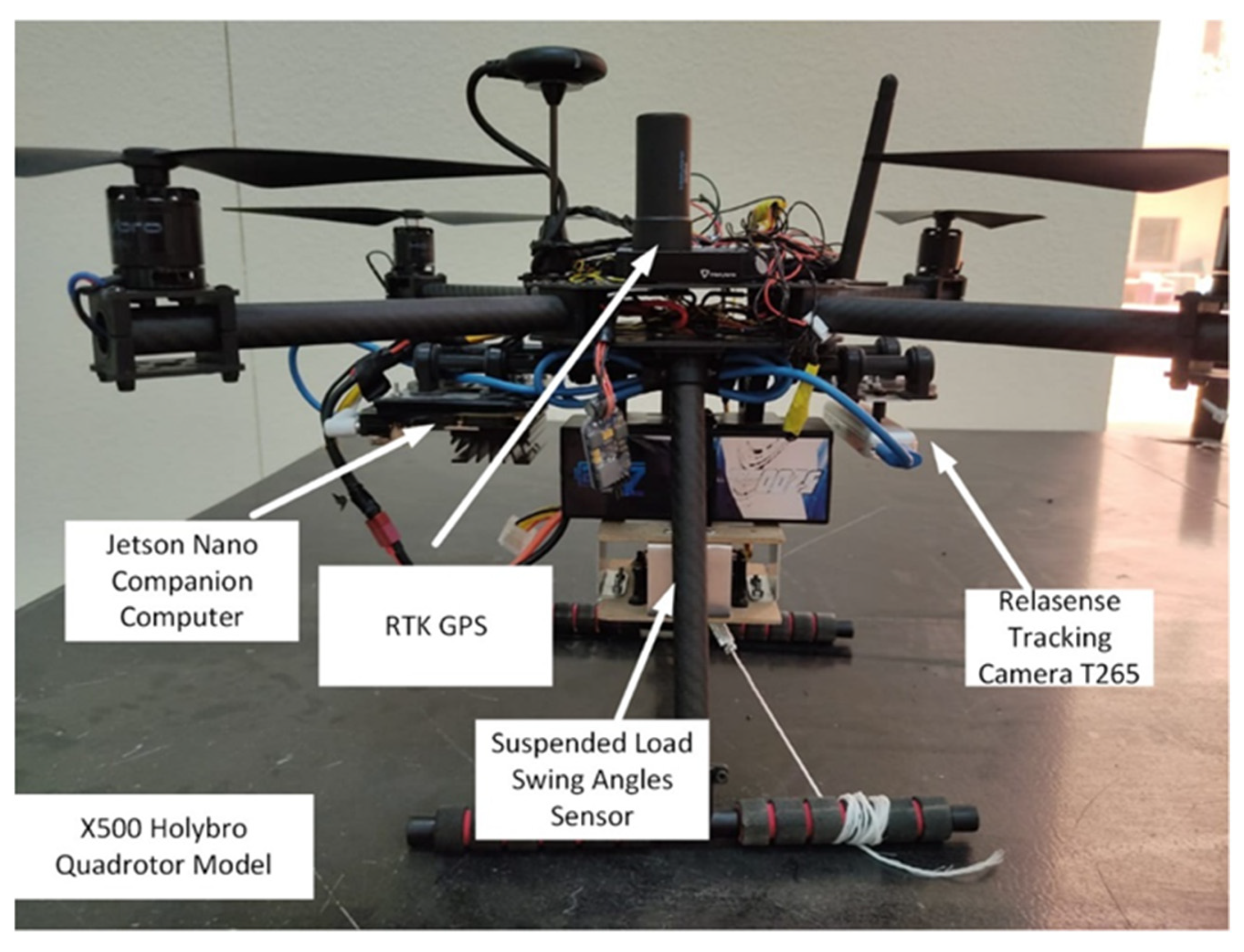
2.3. Determination of Multirotor Mass Properties

Modeling the vehicle dynamics of a multirotor vehicle requires knowledge of the center of mass (COM) and moments of inertia (MOI) of the vehicle. These include the MOI about the pitch, roll, and yaw axes. The test stand was developed to enable the determination of the COM about the yaw axis and the MOI about the yaw, roll, and pitch axes (defined in Figure 7) through experiments. What follows is a brief discussion on the determination of the COM along the yaw axis and the MOI about the three axes.
Determination of the COM along the yaw axis and the moments of inertia about the pitch and roll axes was performed by converting the vehicle into a physical pendulum and applying the physical pendulum theorem. The procedure is discussed in detail in [41]. On the other hand, determination of the MOI about the yaw axis was determined by using the bifilar pendulum method. The technique is described in detail in [42,43,44]. The test setups for determination of the COM and MOI of the X500 Holybro quadcopter are shown in Figure 8.
It should be noted that the accuracy of both the MOI and COM were limited by the measurements taken, including distances between points, time period measurements, and other length measurements. The methods presented here are reliable, of sufficient accuracy, and alternatives to the analytical solutions and the use of CAD models which would be impractical for complex geometries [42].

3. Test Results and Discussion

The proposed test platform was used in the development of an anti-swing controller for a Holybro X500 quadrotor with a suspended load. Some of the physical parameters needed in development include the center of mass of the quadrotor and the moments of inertia of the quadrotor (about the pitch, roll, and yaw axes). These parameters were obtained using the proposed test platform. In addition, the ability of test platform to evaluate the performance of an anti-swing controller on the quadcopter in a safe environment was demonstrated. What follows is a presentation and discussion of results from tests to determine the above-mentioned physical parameters and the use of the test platform for safely testing the performance of an anti-swing controller currently in development.

3.1. Determination of the Quadcopter’s Mass Properties

The center of mass of the quadcopter was determined by considering the dependence of the time period on the location of the pivot. The quadcopter was suspended (at 15 points) on the testbed, as indicated in Figure 8a. The time periods were then determined for different pivot points, as described in [41]. The results are reported in Table 2 and plotted in Figure 9.
The results in Figure 9 indicate that the minimum time periods occurred when the pivot points were at 167 and 437 mm. Consequently, the center of mass was located at 302 mm, corresponding to the center of the minimum period locations (and center of the two sections of the curves). The coordinates and the center of mass were plotted in the quadcopter image in Figure 10 for better visualization.
Determination of the moments of inertia of the quadcopter, about the pitch and roll axes, requires knowledge of the mass of the vehicle, the distances from the pivot to the center of mass, and the periods of oscillation of the quadcopter about the two axes (pitch and roll) (see [41]). The mass or the quadcopter was measured, and the distances between the pivot points and the COM were extracted from the previous experiment. The time periods of oscillation for the quadcopter about the pitch and roll axes were also determined based on the test setup shown in Figure 8b. The results from the experiments are reported in Table 3.
The moments of inertia about the pitch axes could then be computed as discussed in [41], and the moments of inertia about the axis through the COM (but parallel to the later axes) could be determined by applying the transfer of axis formula as follows:
I = I ¯ + m d 2
In Equation (1), I ¯ refers to the inertia about the axis through the COM and d refers to the distances between the COM and the pitch and roll axes (i.e., dp and dr as listed in Table 3). The results for the moments of inertia are reported in Table 4.
To determine the moment of inertia about the yaw axis, the procedure outlined in [42,43,44] was utilized. This required suspending the quadcopter as indicated in Figure 8c and then measuring the distances D and L (described in Figure 11) along with the time period of oscillation of the quadcopter (suspended as a bifilar pendulum). The moment of inertia about the yaw axis was then computed, and the results are reported in Table 5.

3.2. Flight Testing of Holybro X500 Quadcopter

The Holybro X500 quadcopter with an attached suspended load was constrained on the testbed as shown in Figure 12. The quadcopter was able to move and rotate in any direction with appropriate limits on the motion. and without any part of the vehicle coming in contact with the testbed or the restraining cables becoming entangled. The limits on the movement of the vehicle were deliberately chosen to enable it to fly freely within a prescribed region while ensuring that it would not crash in cases of loss of control.
For the test, the quadcopter was made to hover with the restraining cables still loose. A disturbance was then applied to the suspended load (this was done four times for the test). The disturbance entailed displacing the suspended load. The data of the swing angle and the quadcopter angles, including the roll angle, pitch angle, and yaw angle, were recorded and are plotted in Figure 13, Figure 14, Figure 15, Figure 16, and Figure 17, respectively. These results are some of the data that could be used to evaluate the performance of the quadcopter. It should be noted that those data are for the case of the quadcopter without the anti-swing controller.
Figure 13 and Figure 14 show the in-plane and the out-of-plane load swing angles, respectively. The swing load was disturbed four times at approximately 5, 16, 27, and 35 s. These times of disturbances are apparent in Figure 13. In Figure 15, Figure 16, and Figure 17, the roll, pitch, and yaw angles of the quadcopter are plotted. The swing load disturbances are apparent in the quadcopter roll angle figure (Figure 15). The pitch and yaw angles (Figure 15 and Figure 16) appear to have been approximately constant, alluding to the fact that the swing load was displaced in such a way as to cause the vehicle’s angular movement to be vastly in the roll direction.

4. Conclusions

In this work, a simple but novel 6-DOF test platform was designed and built for testing the performance of multirotor flying vehicles. This test platform was designed to perform a variety of tasks, including flight training and experimental determination of the mass properties of any small multirotor vehicle (such as the moments of inertia and center of mass). Moreover, the test platform can be used for multirotor controller in-flight performance testing (including vehicles with suspended loads).
The test platform was successfully used to determine the mass properties of a Holybro × 500 quadcopter. The applicability of the test platform for the in-flight performance testing of a multirotor vehicle was also successfully demonstrated with a Holybro × 500 quadcopter with a suspended load. Based on the tests, it is the authors’ opinion that this simple and cost-effective novel test platform is a powerful and useful piece of equipment for flight testing multirotor vehicles in a safe manner.

Author Contributions

Project administration H.M.O.; conceptualization, H.M.O. and S.M.S.M.; experiments, H.M.O. and S.M.S.M.; writing—review and editing, H.M.O. and S.M.S.M. All authors have read and agreed to the published version of the manuscript.

Funding

The authors gratefully acknowledge Qassim University, represented by the Deanship of Scientific Research, on the financial support for this research under the number (5430-qec-2019–2-2–l) during the academic year 1440 AH/2019 AD.

Institutional Review Board Statement

Not applicable.

Informed Consent Statement

Not applicable.

Data Availability Statement

Not applicable.

Conflicts of Interest

The authors declare no conflict of interest. The funders had no role in the design of the study; in the collection, analyses, or interpretation of data; in the writing of the manuscript, or in the decision to publish the results.

References

  1. Xuan-Mung, N.; Hong, S.-K. A Multicopter ground testbed for the evaluation of attitude and position controller. Int. J. Eng. Technol. 2018, 7, 65–73. [Google Scholar]
  2. Khaligh, S.P.; Martínez, A.; Fahimi, F.; Koch, C.R. A HIL Testbed for Initial Controller Gain Tuning of a Small Unmanned Helicopter. J. Intell. Robot. Syst. 2014, 73, 289–308. [Google Scholar] [CrossRef]
  3. Yu, Y.; Ding, X. A quadrotor test bench for six degree of freedom flight. J. Intell. Robot. Syst. 2012, 68, 323–338. [Google Scholar] [CrossRef]
  4. Bhargava, A. Development of a Quadrotor Testbed for Control and Sensor Development. Master’s Thesis, Clemson University, Clemson, SC, USA, 2008. [Google Scholar]
  5. Hancer, M.; Bitirgen, R.; Bayezit, I. Designing 3-DOF Hardware-In-The-Loop Test Platform Controlling Multirotor Vehicles. IFAC-PapersOnLine 2018, 51, 119–124. [Google Scholar] [CrossRef]
  6. Wang, H.; Azaizia, D.; Lu, C.; Zhang, B.; Zhao, X.; Liu, Y. Hardware in the loop based 6DoF test platform for multi-rotor UAV. In Proceedings of the 4th International Conference on Systems and Informatics (ICSAI), Hangzhou, China, 11–13 November 2017; pp. 1693–1697. [Google Scholar]
  7. Grzonka, S.; Grisetti, G.; Burgard, W. A fully autonomous indoor quadrotor. IEEE Trans. Robot. 2012, 28, 90–100. [Google Scholar] [CrossRef] [Green Version]
  8. Zul Azfar, A.; Hazry, D. A simple approach on implementing IMU sensor fusion in PID controller for stabilizing quadrotor flight control. In Proceedings of the 7th International Colloquium on Signal Processing and Its Applications, Penang, Malaysia, 4–6 March 2011. [Google Scholar]
  9. Santos, M.F.; Silva, M.F.; Vidal, V.F.; Honorio, L.M.; Lopes, V.L.M.; Silva, L.A.Z.; Rezende, H.B.; Ribeiro, J.M.S.; Cerqueira, A.S.; Pancoti, A.A.N.; et al. Experimental Validation of Quadrotors Angular Stability in a Gyroscopic Test Bench. In Proceedings of the 2018 22nd International Conference on System Theory, Control and Computing, Sinaia, Romania, 10–12 October 2018; pp. 783–788. [Google Scholar]
  10. Øyvind, M.; Eivind, S.K. Modeling, design and experimental study for a quadcopter system construction. Master’s Thesis, University of Agder, Agder, Norway, 2011. [Google Scholar]
  11. Veyna, U.; Garcia-Nieto, S.; Simarro, R.; Salcedo, J.V. Quadcopters Testing Platform for Educational Environments. Sensors 2021, 21, 4134. [Google Scholar] [CrossRef] [PubMed]
  12. Paiva, E.; Soto, J.; Salinas, J.; Ipanaque, W. Modeling, simulation and implementation of a modified PID controller for stabilizing a quadcopter. In Proceedings of the 2016 IEEE International Conference on Automatica (ICA-ACCA), Curico, Chile, 19–21 October 2016; pp. 1–6. [Google Scholar]
  13. Ugur, Y.; Irfan, Ö.; Hakan, U.; Ali Riza, G.; Telat, T.; Metin, K.; Cihan, K.; Gökhan, U. Development of the Test Platform for Rotary Wing Unmanned Air Vehicle. Bilecik Seyh Edebali Univ. J. Sci. 2016, 2, 18–24. [Google Scholar]
  14. Filho, J.G.B.F.; Dorea, C.E.T.; Bessa, W.M.; Farias, J.L.C.B. Modeling, Test Benches and Identification of a Quadcopter. In Proceedings of the 2016 XIII Latin American Robotics Symposium and IV Brazilian Robotics Symposium (LARS/SBR), Recife, Brazil, 8–12 October 2016; pp. 49–54. [Google Scholar]
  15. Ömurlu, V.E.; Ahmet, K.; Utku, B.; Engin, S.N.; Sedat, K. A stationary, variable DOF flight control system for an unmanned quadrocopter. Turk. J. Electr. Eng. Comput. Sci. 2011, 19, 891–899. [Google Scholar]
  16. Jatsun, S.; Emelyanova, O.; Martinez Leon, A.S. Design of an Experimental Test Bench for a UAV Type Convertiplane. In Proceedings of the IOP Conference Series: Materials Science and Engineering, Moscow, Russia, 16–17 October 2019; pp. 1–5. [Google Scholar]
  17. Jatsun, S.; Emelyanova, O.; Lushnikov, B.; Martinez Leon, A.S.; Mosquera Morocho, L.M.; Pechurin, A.; Nolivos Sarmiento, C.A. Hovering control algorithm validation for a mobile platform using an experimental test bench. In Proceedings of the IOP Conference Series: Materials Science and Engineering, Moscow, Russia, 16–17 October 2020; pp. 1–7. [Google Scholar]
  18. Ding, C.; Lu, L.; Wang, C.; Li, J. 6-DOF Automated Flight Testing Using a Humanoid Robot Arm. In Proceedings of the 2018 IEEE 14th International Conference on Automation Science and Engineering, Munich, Germany, 20–24 August 2018. [Google Scholar]
  19. Dukes, T.A. Maneuvering Heavy Sling Loads Near Hover Part I: Damping the Pendulous Motion. J. Am. Helicopter Soc. 1973, 18, 2–11. [Google Scholar] [CrossRef]
  20. Liu, D.T. In-Flight Stabilization of Externally Slung Helicopter Loads; U.S. Army Air Mobility Research Development Laboratory: Fort Eustis, VA, USA, 1973. [Google Scholar]
  21. Gupta, N.K.; Bryson, A.E., Jr. Automatic Control of a Helicopter with a Hanging Load; U.S. Army Air Research and Monility COnand Ames Directorate: Moffett Field, CA, USA, 1973. [Google Scholar]
  22. Hutto, A.J. Flight-Test Report on the Heavy-Lift Helicopter Flight-Control System. Am. Helicopter Soc. 1976, 21, 32–40. [Google Scholar] [CrossRef]
  23. Ivler, C.M.; Powell, J.D.; Tischler, M.B.; Fletcher, J.W.; Ott, C. Design and Flight Test of a Cable Angle/Rate Feedback Flight Control System for the RASCAL JUH-60 Helicopter. In Proceedings of the American Helicopter Society 68th Annual Forum, Fort-Worth, TX, USA, 1–3 May 2012. [Google Scholar]
  24. Ivler, C.M.; Powell, J.D.; Tischler, M.B.; Fletcher, J.W.; Ott, C. Design and Flight Test of a Cable Angle Feedback Flight Control System for the RASCAL JUH-60 Helicopter. Am. Helicopter Soc. 2014, 59, 042008. [Google Scholar] [CrossRef]
  25. Krishnamurthi, J.; Horn, J.F. Helicopter Slung Load Control Using Lagged Cable Angle Feedback. Vert. Flight Soc. 2015, 60, 1–12. [Google Scholar] [CrossRef]
  26. Scaramal, M.; Enciu, J.; Horn, J. Active Stabilization of Slung Loads in High-Speed Flight Using Cable Angle Feedback. Vert. Flight Soc. 2019, 64, 1–11. [Google Scholar] [CrossRef]
  27. Herzog, M. Design, Implementation and Analysis of a Controller for a Load Suspended From an Aerial Vehicle. Master’s Thesis, KTH, Skolan för Elektro-Och Systemteknik (EES), Stockholm, Sweden, 2016. [Google Scholar]
  28. Pereira, P.O.; Herzog, M.; Dimarogonas, D.V. Slung load transportation with a single aerial vehicle and disturbance removal. In Proceedings of the 24th Mediterranean Conference on Control and Automation, Athens, Greece, 21–24 June 2016; pp. 671–676. [Google Scholar]
  29. Dhiman, K.K.; Kothari, M.; Abhishek, A. Autonomous Load Control and Transportation Using Multiple Quadrotors. Aerosp. Inf. Syst. 2020, 17, 417–435. [Google Scholar] [CrossRef]
  30. Guo, M.; Gu, D.; Zha, W.; Zhu, X.; Su, Y. Controlling a Quadrotor Carrying a Cable-Suspended Load to Pass Through a Window. J. Intell. Robot. Syst. 2019, 98, 387–401. [Google Scholar] [CrossRef]
  31. Robin Amsters, N.S.; Quinten, L. Evaluation of Low-Cost/High-Accuracy Indoor Positioning Systems. In Proceedings of the Fourth International Conference on Advances in Sensors, Actuators, Metering and Sensing, Athens, Greece, 24–28 February 2019; pp. 15–20. [Google Scholar]
  32. PX4. Visual Inertial Odometry. Available online: https://docs.px4.io/master/en/computer_vision/visual_inertial_odometry.html (accessed on 28 May 2021).
  33. Omar, H.M.; Nayfeh, A.H. Gantry cranes gain scheduling feedback control with friction compensation. J. Sound Vib. 2005, 281, 1–20. [Google Scholar] [CrossRef]
  34. Frsky. M9-R. Available online: https://www.frsky-rc.com/product/m9-r/ (accessed on 6 November 2021).
  35. Hyla, P.; Szpytko, J. Vision Method for Rope Angle Swing Measurement for Overhead Travelling Cranes-Validation Approach. In Proceedings of the 13th International Conference on Transport Systems Telematics, TST 2013, Katowice-Ustroń, Poland, 23–26 October 2013; pp. 370–377. [Google Scholar]
  36. Jain, R.P.K. Transportation of Cable Suspended Load Using Unmanned Aerial Vehicles: A Real-Time Model Predictive Control Approach. Master’s Thesis, Delft University of Technology, Delft, The Netherlands, 2015. [Google Scholar]
  37. Goodarzi, F.A.; Lee, D.; Lee, T. Geometric stabilization of a quadrotor UAV with a payload connected by flexible cable. In Proceedings of the American Control Conference, Portland, OR, USA, 4–6 June 2014. [Google Scholar]
  38. Goodarzi, F.A.; Lee, D.; Lee, T. Geometric Control of a Quadrotor UAV Transporting a Payload Connected via Flexible Cable. Int. J. Control. Autom. Syst. 2015, 13, 1486–1498. [Google Scholar] [CrossRef] [Green Version]
  39. PX4. Real Time Kinetics (RTK). Available online: https://docs.px4.io/master/en/advanced_features/rtk-gps.html (accessed on 28 May 2021).
  40. Intel® RealSense™ Tracking Camera. Available online: https://dev.intelrealsense.com/docs/tracking-camera-t265-datasheet (accessed on 6 November 2021).
  41. Kladivova, M.; Mucha, L. Physical pendulum-a simple experiment can give comprehensive information about a rigid body. Eur. J. Phys. 2014, 35, 025018. [Google Scholar] [CrossRef]
  42. Krznar, M.; Kotarski, D.; Piljek, P.; Pavković, D. On-line Inertia Measurement of Unmanned Aerial Vehicles using on board Sensors and Bifilar Pendulum. Interdiscip. Complex Syst. INDECS 2018, 16, 149–161. [Google Scholar] [CrossRef] [Green Version]
  43. Jardin, M.R.; Mueller, E.R. Optimized Measurements of Unmanned-Air-Vehicle Mass Moment of Inertia with a Bifilar Pendulum. J. Aircr. 2009, 46, 763–775. [Google Scholar] [CrossRef]
  44. Then, J.W. Bifilar Pendulum-An Experimental Study for the Advanced Laboratory. Am. J. Phys. 1965, 33, 545–547. [Google Scholar] [CrossRef]
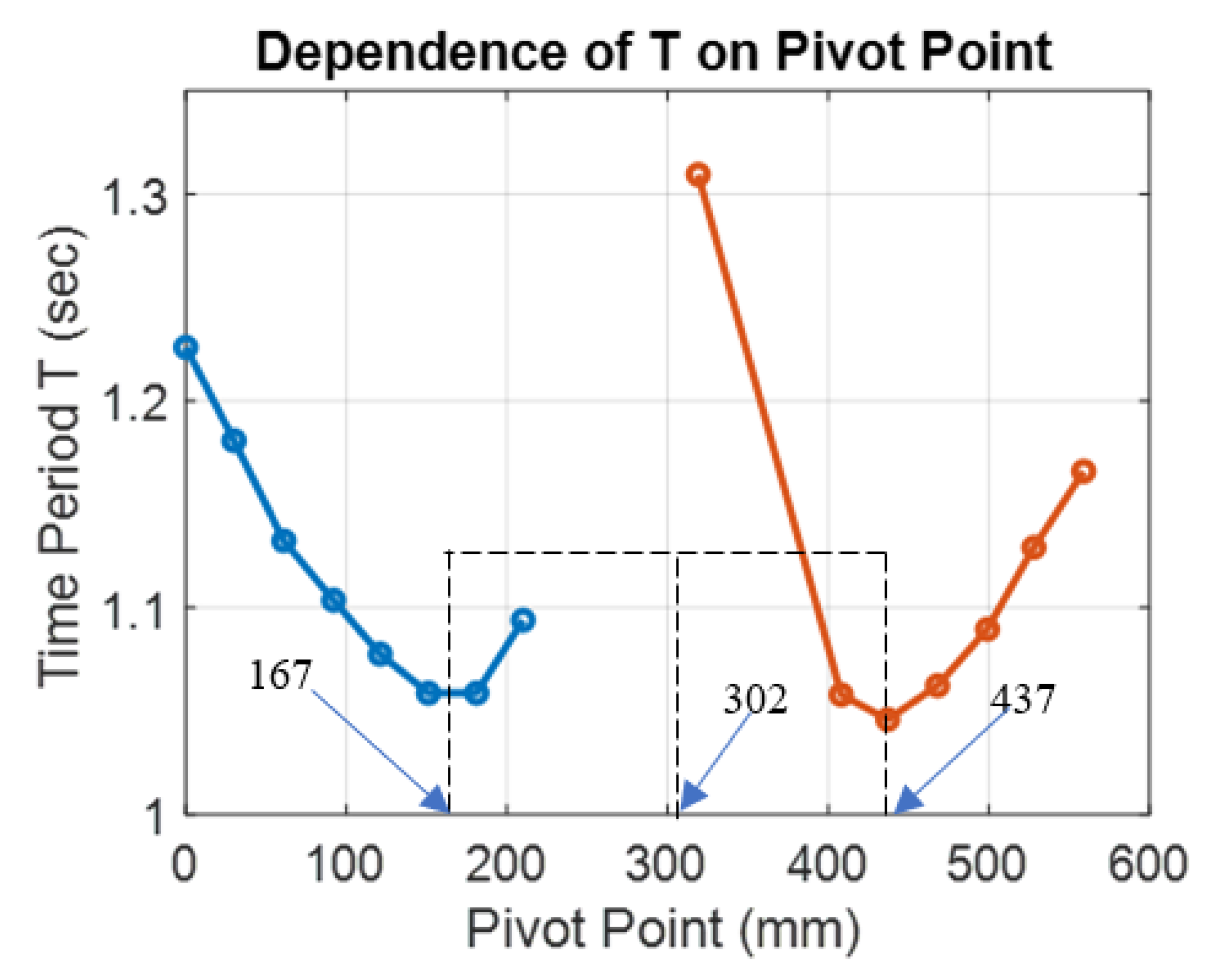
Figure 1. CAD model of the multiuse indoor test platform for multirotor testing: (a) Top view; (b) isometric view; (c) front view; (d) side view.
Aerospace 08 00355 g001aAerospace 08 00355 g001b
Figure 2. Region in the test platform where the flight of the multirotor is restricted.
Aerospace 08 00355 g002
Figure 3. Position sensing equipment: (a) Realsense T265 tracking camera. (b) Jetson nano A57 companion computer.
Aerospace 08 00355 g003
Figure 4. Description of the swing angles. In-plane swing angle (ɸL) and out-of-plane swing angle (ɵL).
Aerospace 08 00355 g004
Figure 5. Descriptions of the connections of the pixhawk to the camera and the companion computer: (a) connections of the tracking camera to the companion computer and Pixhawk board; (b) telemetry pins on the pixhawk.
Aerospace 08 00355 g005
Figure 6. X500 Holybro quadcopter with a jetson computer, an RTK GPS, and a relasense camera installed for indoor and outdoor testing.
Aerospace 08 00355 g006
Figure 7. Axes about which the moments of inertia were to be determined.
Aerospace 08 00355 g007
Figure 8. Test setup for determination of the mass properties of the X500 Holybro quadcopter: (a) determination of the COM; (b) determination of MOI about the pitch and roll axes; (c) determination of the MOI about the yaw axis.
Aerospace 08 00355 g008
Figure 9. Axes about which the moments of inertia were to be determined.
Aerospace 08 00355 g009
Figure 10. Location of the quadcopter’s center of mass.
Aerospace 08 00355 g010
Figure 11. Depiction of a quadcopter bifilar pendulum.
Aerospace 08 00355 g011
Figure 12. Restricted quadrotor with a suspended load in the test platform.
Aerospace 08 00355 g012
Figure 13. In–plane load swing angle ɸL (as described in Figure 4).
Aerospace 08 00355 g013
Figure 14. Out–of–plane load swing angles ƟL (as described in Figure 4).
Aerospace 08 00355 g014
Figure 15. Quadcopter roll angle.
Aerospace 08 00355 g015
Figure 16. Quadcopter pitch angle.
Aerospace 08 00355 g016
Figure 17. Quadcopter yaw angle.
Aerospace 08 00355 g017
Table 2. Results from experimental to determine the COM.
NumberCoordinate (mm)Time Period T (sec)
101.226
2301.1808
3611.1324
4921.1036
51211.0776
61511.0588
71811.0588
82101.094
93191.3096
104081.058
114371.046
124681.0624
134991.0896
145281.1292
155591.166
Table 3. Results from experimentation used to determine the moments of inertia.
Description of ItemSymbolValue
Total Quadcopter massm1.585 kg
Distance between pivot at the pitch axis and COMdp57.62 mm
Distance between pivot at the roll axis and COMdr57.816 m
Period of oscillation about the pitch axisTp1.026 s
Period of oscillation about the roll axisTr1.055 s
Table 4. Results from experimentation used to determine the moments of inertia.
Description of ItemSymbolInertia Values (kg·m2)
Pitch AxisRoll Axis
Axis through Pivot pointI0.0238990.025326
Axis through COM I ¯ 0.0186364820.020027499
Table 5. Moment of inertia of the X500 quadcopter about the yaw axis.
Description of ItemSymbolValue
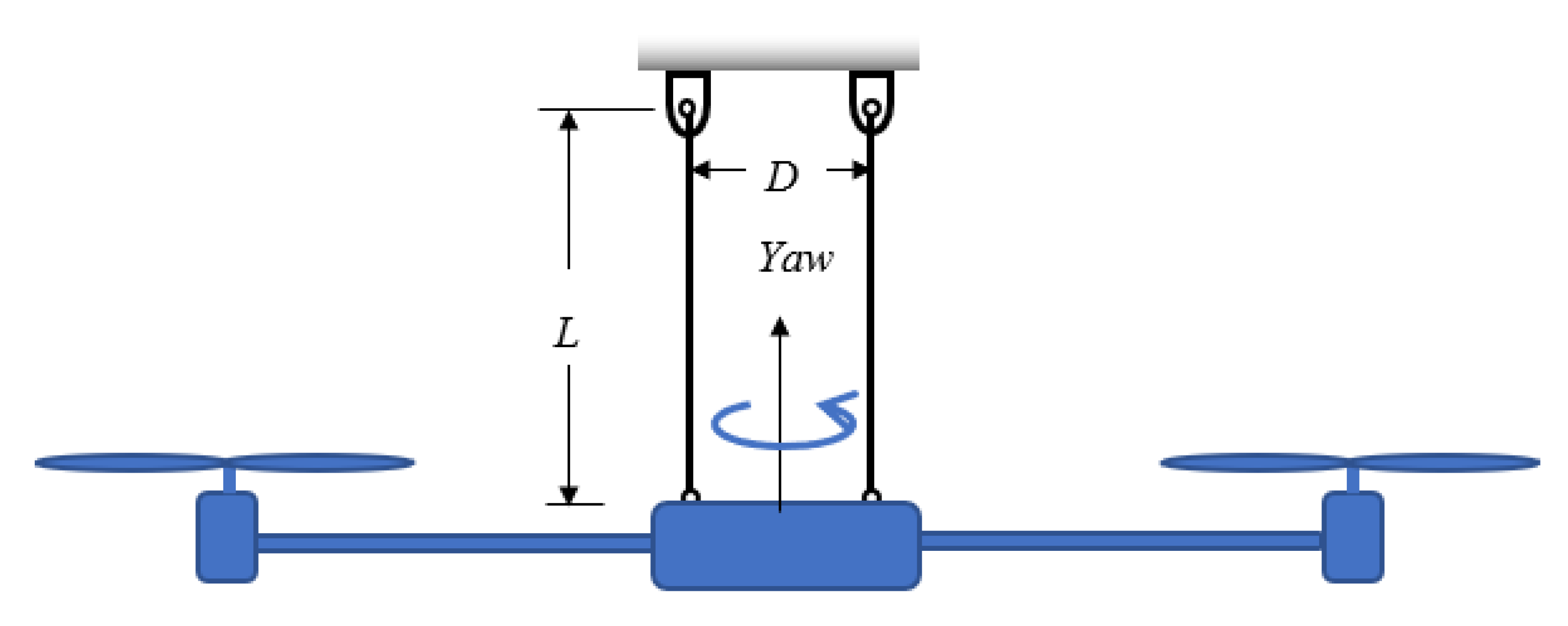
distance between the two suspension cables (see Figure 9)D0.146 m
length of the suspension cable (see Figure 9)L1.066 m
Period of oscillation about the yaw axisT3.7608 s
Moment of inertia about the yaw axis (axis through COM)Iyaw0.02788 kg·m2
Publisher’s Note: MDPI stays neutral with regard to jurisdictional claims in published maps and institutional affiliations.

