1. Introduction
The turbulent flow downstream of a bluff body is of fundamental interest to combustion applications for the assessment of flame anchoring techniques as well as to the aerodynamic design of structural elements of airborne or ground devices [
1,
2,
3,
4]. Bluff bodies are an important ingredient, alone or in combination with a swirler, in flame stabilization devices. The flow distribution downstream of a bluff body geometry affects flame placement and has a significant impact on the combustion stability, efficiency and emissions. Its flow dynamic characteristics also play a crucial role in the development of the turbulent properties of the adjacent wake. Further understanding of bluff body wake aerodynamics and its implications in flame stabilization performance can be provided by mapping the topology of the flow field under non-reacting conditions.
As a consequence, numerous experimental and computational works have been devoted to provide further insight into the aerodynamic design properties, wake flow topologies, turbulence characteristics, inert mixing disposition and time-dependent flow behavior in a diversity of bluff shapes e.g., [
5,
6,
7,
8,
9]. These works focused on the examination of the isothermal recirculating bluff body flow fields, either with regard to a counterpart reacting set up e.g., [
10,
11,
12] or as part of the aerodynamic design of structural elements e.g., [
13,
14].
Regarding the combustion applications, the majority of these studies has, so far, concentrated on comparing global properties and turbulent characteristics in the baffle’s wake, between cold and reacting flows, with particular emphasis placed on configurations pertaining to, either diffusion e.g., [
5,
15,
16,
17] or fully premixed combustion applications e.g., [
8,
18,
19,
20].
More recent investigations have been extended on variants of the usual geometry set-ups in an effort to accommodate studies of partially premixed or stratified inlet fuel–air mixture stabilization arrangements [
21,
22,
23,
24,
25,
26,
27,
28,
29,
30]. Such concepts have been under intensive investigation because they offer an attractive and flexible alternative that improves and promotes the lean premixed combustion concept, which is more frequently used in practical combustion systems. The majority of the previously reported studies on bluff body flow and flame stabilization has focused on examining stand-alone bluff geometries placed against a cross flow [
6,
27,
31,
32,
33,
34,
35].
In the present study, we extend the previously reported in the literature, standard, isolated bluff body configuration by introducing a further complexity regarding the influence of the pre-conditioning of the flow approaching the bluff body under study, as has been demonstrated in [
36]. Specifically, here we address the non-reacting flow performance of commonly used bluff body stabilizers operating in combination with an upstream fuel–air premixing module which, in various forms, represents a configuration frequently encountered in practical systems. In such partially premixed arrangements the aero-thermodynamic coupling between the integrated fuel–air premixer section and the individual baffle stabilizer itself, plays a functional role in the overall wake development and stabilization properties [
12,
30,
37,
38].
Within this context, the aim of the present effort is to perform a systematic and parametric investigation of the performance of a variety of axisymmetric afterbody baffle shapes, operated in conjunction with a preceding upstream premixing arrangement, similar to the one described in [
12,
30,
37,
38], that facilitates regulation of the flow and mixing profiles that supply the bluff body wake. The turbulent flow, within this upstream fuel–air premixer, is interacting with the actual stabilizer flow characteristics, controlling the level and shape of flow and mixture inhomogeneities at the inlet to the main combustion zone as well as its dispositions across the anchoring region. A number of studies has focused on the cold flow and reacting characteristics downstream of the currently investigated premixer arrangement, combined solely with a disk shaped baffle, operated over a range of inlet mixture conditions. These respective investigations concentrated on the study of the scalar mixing properties for different baffle shapes [
38] and on the reacting properties with or without the impact of swirl [
11,
24,
37,
39], under stratified or fully premixed inlet mixture conditions. Additionally, investigations regarding the effect of both stratification and preheat on the reacting front have been presented in [
12,
30,
40], while in [
41] the authors have discussed the influence of acoustic modulation of the incoming velocity and equivalence ratio gradient on the combustion zone.
Nevertheless, the non-reacting flow fields downstream of a wider range of baffles, have not been previously explicitly examined or discussed. Therefore, the current cold flow study represents an independent parametric investigation of a diverse range of bluff body shapes, which are here coupled to an upstream premixer, double cavity section, with the objective to evaluate individual operating features that strongly affect anchoring, flame stabilization and downstream wake development in a counterpart reacting set up.
Important operating characteristics are the trailing edge aerodynamics, the entrainment capability, the recirculation strength, the turbulence intensity along the reacting front and the mean and turbulent strain field near the flanks of the recirculation where the anchoring region most usually resides. Studies under isothermal conditions are of great value despite the alterations that may be induced by the reactions and can crucially assist in the delineation of optimum selections amongst the multiplicity of possible stabilizer combinations during the early stages of burner design. Along these lines, and also based on the combustion properties of the employed reacting fuel mixture, such as flame speeds, ignition delays, extinction stretches and diffusional behaviors, one can identify the most convenient baffle candidate for efficient flame stabilization.
Two dimensional particle image velocimetry (PIV) measurements of these isothermal flows have been carried out to provide detailed mean and fluctuating velocity fields and allow the evaluation of global and turbulent structural flow properties in the near wake of a range of premixer/bluff body shapes.
The presented data and analysis, combined with information from previous works e.g., [
38], aims at providing a systematic and extensive description of the cold flow and mixing characteristics for the range of investigated baffles. The measurements could also be suitably exploited for the assessment of simulation methodologies and turbulence models. Additionally, such results could also be useful in the improvement of flame stabilization procedures of alternative fuels, biofuels or hydrogen blends which present distinct and challenging combustion features.
5. Results and Discussion
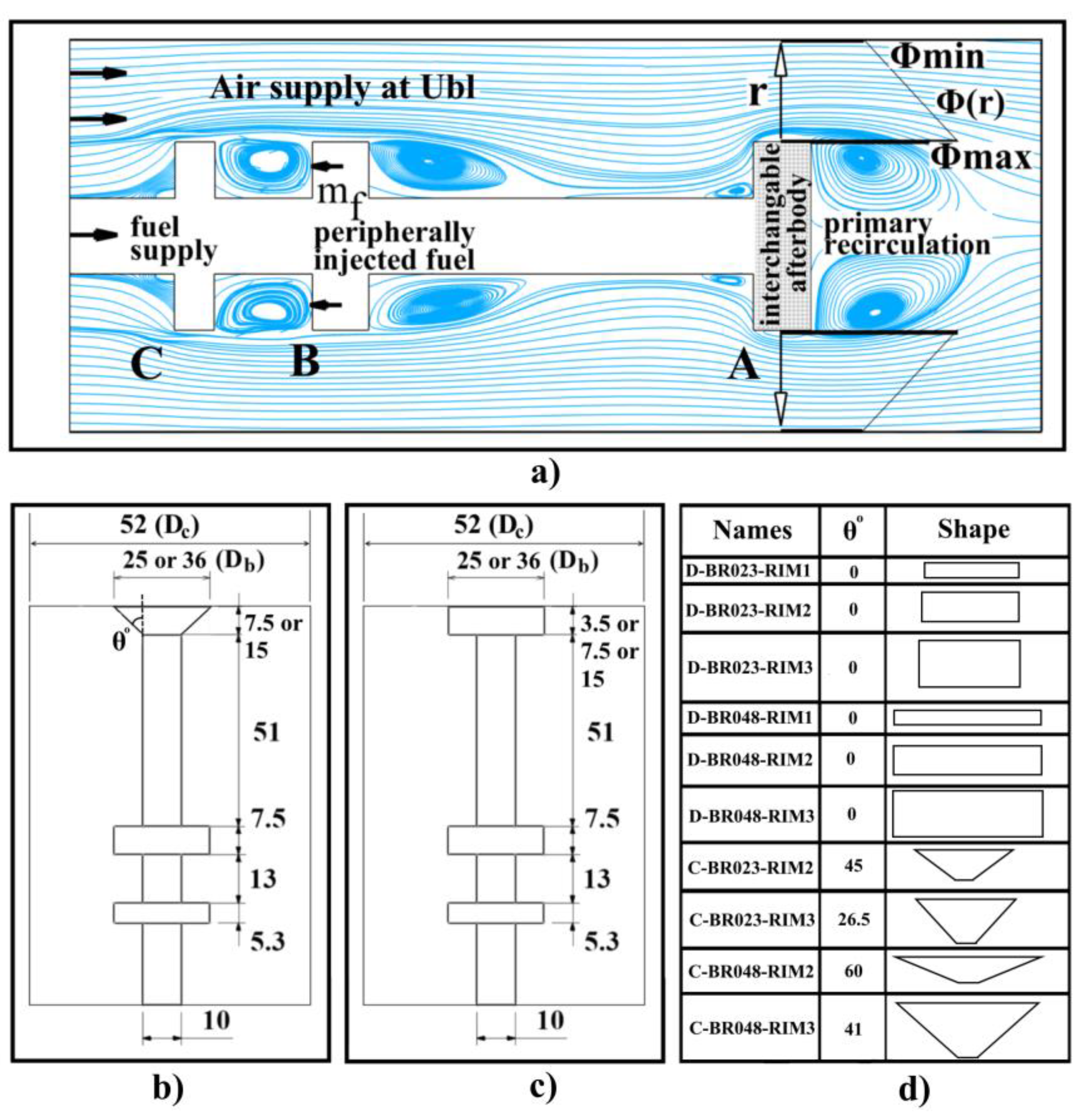
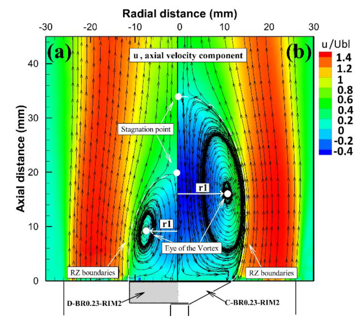
Figure 2 depicts the overall mean flow structure of the recirculation zone for two stabilizer configurations, D-BR023-RIM2 and C-BR0.23-RIM2. The 2D streamline plots of the axial (u) and radial (v) velocity vectors are superimposed over the time-averaged axial velocity contour fields, illustrating the toroidal shear layers and the disposition of the near wake recirculation regions.
The zero or stagnation streamline is also depicted by the white dashed line, which demonstrates the recirculation zone boundary. It extends from the rim edge of the baffle up to the reattachment point, where the air flow converges toward the stagnation point along the centerline. Based on these boundaries the length and width of the recirculation zone can be determined. The illustrated recirculation zone features follow similar dispositions for the remaining of the investigated afterbody baffles with quantitative differences mainly encountered with regard to the extent, formation and strength of the reverse flow zone, as indicated in
Figure 3.
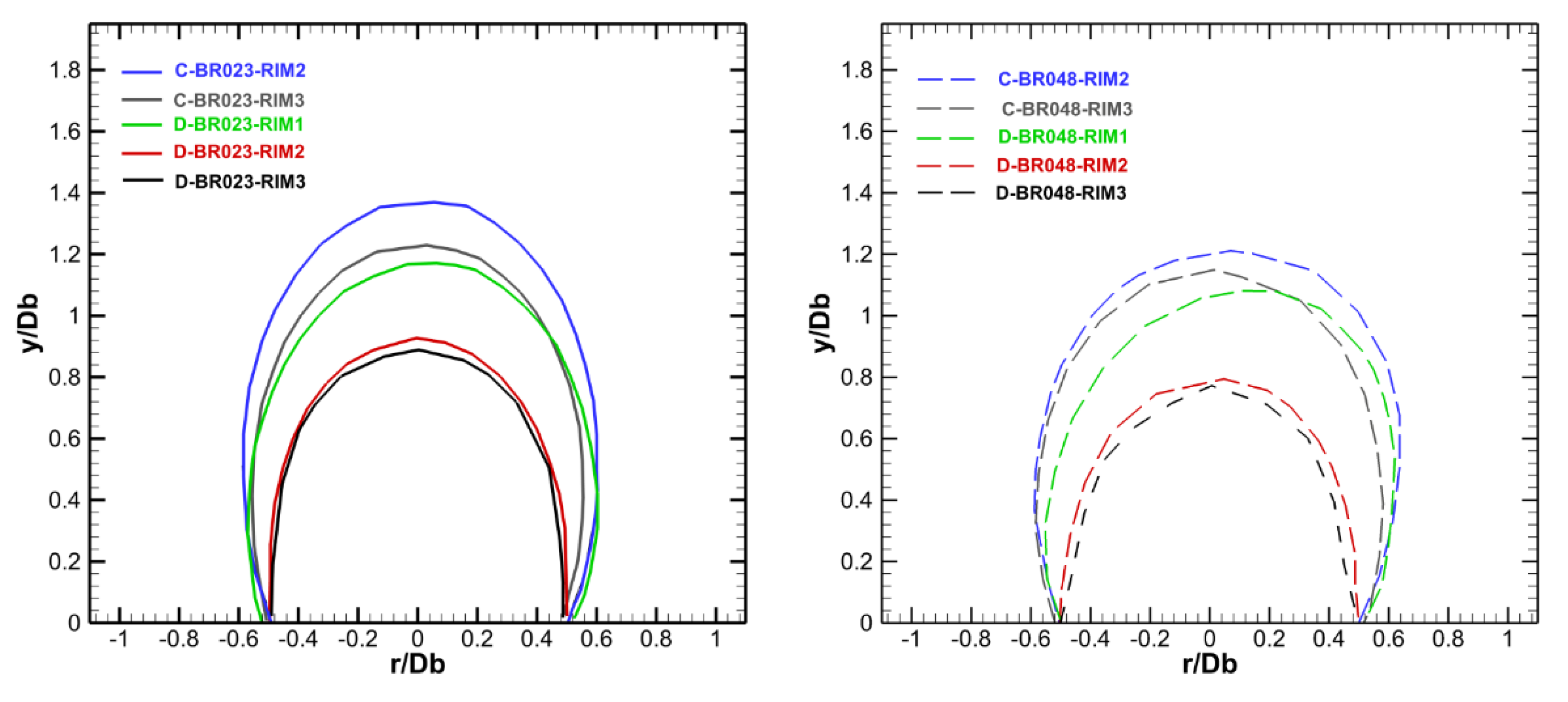
Figure 3 displays the non-dimensional mean axial velocity distributions for all investigated cases. Bluff body shape and blockage ratio variations result in modifications of the geometrical characteristics of the reverse flow envelope. Cone shaped bluff bodies, and particularly those with the steeper angle, form larger recirculation zones than the disk-shaped ones, as a result of the larger deflection angle of the flow issuing at their trailing edge, with an attendant longer and wider reverse flow zone. It was also noticed that in the case of the thin rim disk (D-BR0.48-RIM1), the recirculation zone exhibited an asymmetric behavior, as also observed in [
43]. An increase in the thickness of the disk rim shortened the recirculation zone bubble by about 15% for BR0.23 and 25% for BR0.48 and moderately reduced back flow velocities, retarding the RZ strength. Additionally, thicker baffles proved more capable at maintaining a symmetric wake development regardless of the blockage ratio.
The stagnation points for D-BR0.23-RIM2 and D-BR0.23-RIM3 were located close to y/D
b = 0.9, whereas, for the thinner disk, D-BR0.23-RIM1 and the cone, C-BR0.23-RIM3, the reattachment was encountered at about y/D
b = 1.2. For C-BR0.23-RIM2 the recirculation zone length was extended up to y/D
b = 1.34. Specifically, thicker disks produced shorter lengths (of about 0.77 D
b) than the thinner disk (1.03 D
b). Moreover, the RZ of disk-shaped baffles was reduced compared to the C-BR0.48-RIM2 (1.17 D
b) and C-BR0.48-RIM3 (1.14 D
b) cases,
Table 1. Finally, an increase in BR values, for the disk shaped bluff bodies, notably lengthens the RZ by 22% for RIM2, 19.5% for RIM3 and 11% for RIM1 case, a trend implying a diminishing impact of blockage on the narrower disks.
In overall, coned shaped bluff bodies produced longer RZ lengths than disks, i.e., ranging from 41 to 45% for BR0.23 and 48 to 53% for BR0.48 independently of the bluff body thickness. It should also be mentioned that the off-axis placement of the reattachment position for D-BR0.48-RIM1 baffle at (r/D
b, y/D
b) = (0.2, 1.08) was the result of a distinct and persistent asymmetry, which was interrelated to this high blockage ratio thinner disk; such a behavior has also been reported and discussed for a similar high blockage ratio single disk configuration by [
43].
The maximum non-dimensioned axial backflow velocities (U
rec,max/U
bl) and the axial location where these maximum reverse flow velocities are encountered (X
rec,max/D
b), are also presented in
Table 1. The strength of the backflow is important in practical flame stabilizers, since it is directly related to the capacity of the body to promote higher entrainment rates and longer residence times [
6,
44]. Maximum back flow velocities were found in the cases of the cone shaped and thin disk afterbodies for BR0.48, e.g., C-BR0.48-RIM2, C-BR0.48-RIM3 and D-BR0.48-RIM1. This behavior can be traced to the flow trajectory around the sharper trailing edge angle of these geometries. Both D-BR048-RIM2 and D-BR048-RIM3 induced similar and reduced back-flow velocities, (U
rec,max/U
bl = 0.37), which quickly recovered to positive values at y/D
b = 0.77. On the other hand, for the smaller blockage, the minimum reverse flow velocities were produced by the thicker rim disks and particularly the D-BR0.23-RIM3 case (U
rec,max/U
bl = 0.31), while for the cone shaped bodies minimum reverse flow velocities were found for the thicker cone, e.g., C-BR0.23-RIM3 case (U
rec,max/U
bl = 0.50).
Figure 4 displays the locus of the separation streamline, non-dimensionalized with the bluff body diameter of each different afterbody, providing an indication of the impact of the bluffness on the size and placement of the recirculation torus. The position of the separation or zero streamline (
ψ) was determined by the following expression:
for several axial measurement stations up to the stagnation point.
The dimensional recirculation lengths were found to increase with baffle diameter, although when non-dimensionalized with the diameter of the baffle, an inverse trend was obtained.
For BR0.23 cases, the largest recirculation zone was established by the C-BR0.23-RIM2 baffle with a length, L, and a width, W, of 1.34 and 1.19 Db, respectively, with the results of the blunt cone (C-RIM3) and the thin disk (D-RIM1) recirculation sizes following the trend of the C-BR0.23-RIM2 case. On the other hand, D-BR0.23-RIM2 and D-BR0.23-RIM3 bodies have similar RZ sizes, both producing significantly narrower and shorter recirculation boundaries. The above described trends were also followed closely by the BR0.48 baffles. Those trends signify an inverse relationship between the blockage ratio and the non-dimensional recirculation zone extend, where smaller blockage ratios result in larger recirculation zones, regardless of the studied after body shapes.
For cone shaped bluff bodies and smaller thickness disks, the location of the zero-streamline close to the bluff body trailing edge, indicates larger and positive (with respect to axial flow direction) flow deflection angles ranging from 18° to 34° (
Table 1), causing a wider spread of the annular jet and of the subsequently developing wake. The thick disk baffles (D-RIM 2 and 3) result in a more streamlined flow with almost negative angles ranging from −2° to −5°, implying a diminishing radial velocity component contribution.
Furthermore, the L/W ratio [
4], which represents an approximate measure of the rate of spread of the recirculation zone, is given in
Table 1, implying a relative independency from the geometry of the bluff body. More significantly, this ratio was found to decrease by 10–15% when doubling the blockage ratio, by 17–20% as we move from the cone to the disk and by 5% when increasing the bluff body thicknesses.
A synopsis of the inlet conditions and some global performance values related to the near wake results are given in
Table 1.
The recirculating mass within the primary zone,
, has also been determined, using the following equation as described in [
38], non-dimentionalized by the inlet air mass through the annular exit plane,
:
where,
is the density of the fluid,
is the axial component of the velocity,
is the distance from the centerline of the bluff body, and r1 is the distance from the axis of the bluff body to the eye of the primary vortex (see
Figure 2). These values indicate that the RZ size correlates rather satisfactorily with the engulfed recirculating mass [
45], apart from the thinner disk cases. Most likely this inconsistency occurs due to the intense asymmetric recirculating wake development in this geometry, a behavior that deteriorates at the larger blockages.
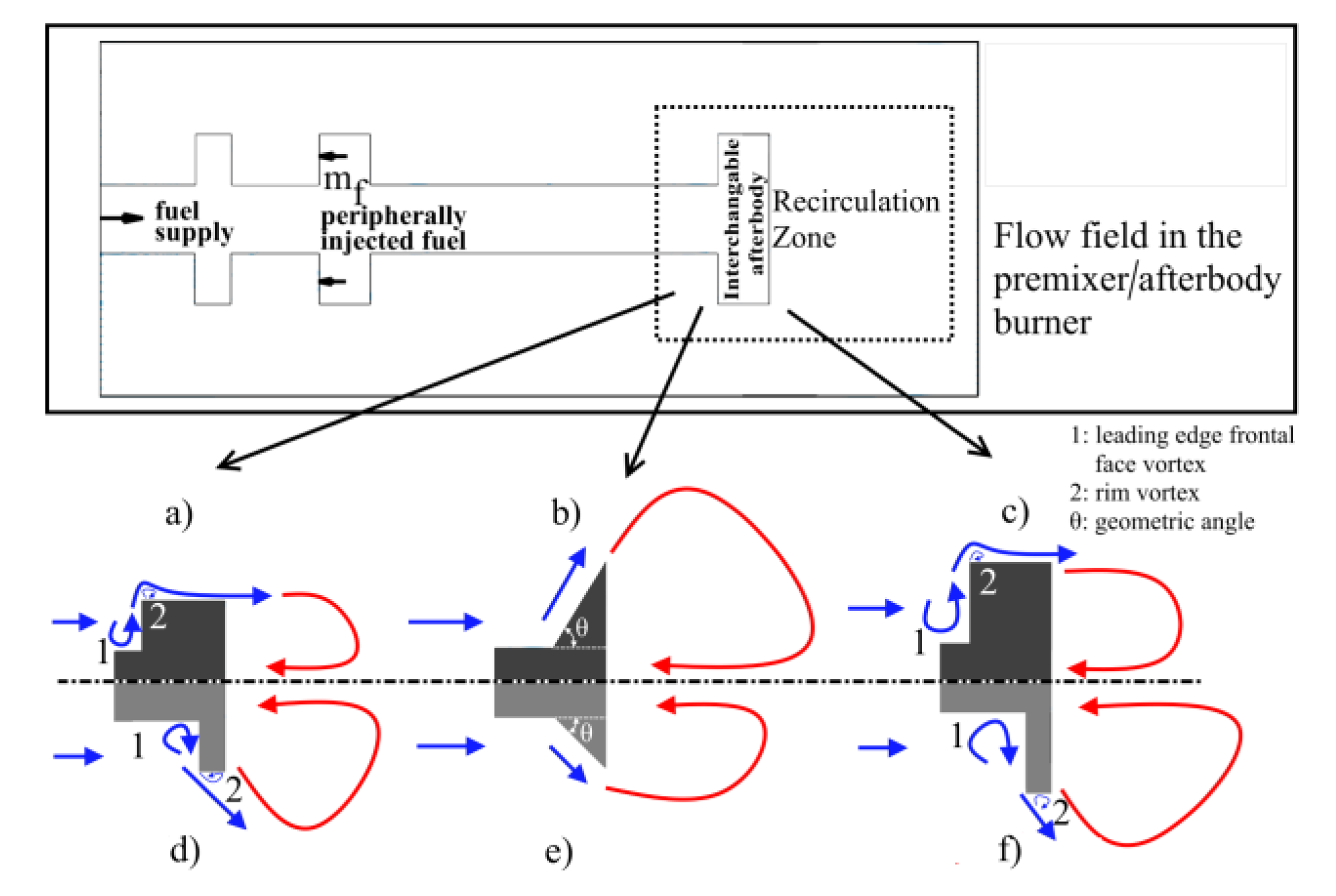
The variations in the flow features, produced by selected representative bluff body geometries, are schematically illustrated in terms of the flow disposition around the afterbody exit plane and within the recirculation region,
Figure 5.
The leading bluff body face shape and the rim edge play a significant role in determining the flow deflection and re-ingestion within the backflow region. As a result, the emanating flow angle is not always aligned with the geometrical trailing edge angle, as indicated in
Table 1.
More specifically, it was observed that in the case of the high blockage cones the shear layer distribution followed the geometrical angle of the baffle, whilst in the smaller blockage ratio cone the shear layer did not appear to be an extension of the geometrical angle. On the other hand, in disk shaped baffles, the exiting flow deflection appeared to be influenced by both rim thickness and blockage. The thinner rim disks appeared to exhibit an inherently unstable shear layer detachment, resulting in a non-uniform circumferential flow ejection angle and the establishment of an asymmetric recirculation. However, in the thicker rim disks (RIM3) the flow angle became almost parallel to the geometrical trailing edge angle.
Moreover, the flow emanating from the disk exit plane is affected by the quality of the flow exiting from the upstream disk cavity formation and the two established toroidal vortices i.e., the leading edge frontal face vortex (1) and the rim vortex (2) [
38,
46] as depicted in
Figure 5. The strength and size of both these vortices depend on the premixing cavity arrangement, the blockage ratio and the rim thickness for the same upstream inlet conditions.
For the thick rim cases, the rim vortex was followed by immediate flow reattachment on the rim length (
Figure 5a,c). As the disk thickness narrows, the rim vortex gradually occupies a greater extent of the rim length and its effect on the trailing edge flow angle is augmented. This trend became more pronounced for the thinner rims, where the leading face toroidal vortex, vortex (2), plays a more significant role in defining the flow deflection at the trailing edge (
Figure 5d,f). The leading face toroidal vortex (1) implicitly transforms the blunt disk front into a more aerodynamically streamlined forebody shape. On the other hand, the rim vortex creates an effective larger BR than the geometric one and at the same time promotes operation with lower deflection angles. Overall, it is important to distinguish between geometric and aerodynamic bluffness, as the estimation of the former is based on the diameter of the baffle and the estimation of the latter is based on the specific aerodynamic features surrounding the baffle.
All these effects reflect on the efficiency of flow stabilization for each studied configuration, as related to the shear layer deflection, the mass entrainment levels, the pressure drop, the strain rates acting in the near wake region and the possibility of inducing an inherently unstable behavior. These characteristics can be found useful in determining the optimal configuration for flame stabilization, over a wide range of fuels and mixture compositions, each of which may exhibit individual flame anchoring properties and challenges, i.e., flame speeds and extinction stretches.
To emphasize the significance of the near wake region, flow field properties such as the turbulent kinetic energy and the total and turbulent strains, have been also estimated and compared, along the streamline that encapsulates the recirculating wake region and these are associated with steep gradients of turbulent transport.
The turbulent kinetic energy (
) and the mean strain rate (
) were determined using the following expressions:
where
is the bulk blocked axial velocity and
and
the RMS axial and radial velocity components respectively.
The spatial distributions of
are illustrated in
Figure 6, where the assumption has been made that the azimuthal fluctuating velocity component contribution,
, is equal to the radial,
, in this axisymmetric flow.
The smaller blockage ratio baffles generally produce lower normalized values than the BR0.48 baffles at levels ranging from 20% to 35%, as a result of lower radial and axial RMS velocity component values. Maximum generation of levels for the disk shaped bodies was identified close to the bluff body trailing rim edge, along the shear layer region, while for the cones maximum levels were encountered in the vicinity of the recirculation zone reattachment region. This distinct difference could be attributed to the higher radial velocity components attained by the cones, at the RZ reattachment position, as a result of the stronger deflection of the shear layer emanating from the cone. Similarly, decreasing the geometrical angle of the cone shaped bodies contributed to a higher accumulation of production in the region at and around the stagnation point. The D-BR0.48-RIM1 case produces a similar trend to the C-BR0.48-RIM2 configuration partly due to the initial higher deflection of the shear layer at the rim edge and partly due to the non-symmetric toroidal vortex formation, which results in an enhanced turbulent activity at the oscillating reattachment position.
Moreover, it becomes apparent that the disk rim thickness plays a significant role in the disposition of the
along the wake. For instance, by doubling the rim thickness, from RIM1 to RIM2, the local maxima at the flanking shear layer were reduced by 36% and attained a more cylindrical shape when compared to the thinner disk
field. Further moving from RIM2 to RIM3, resulted in a substantial reduction in
by about 46%. Comparable results were derived for higher blockage ratio baffles, with peak
levels at 18%, 8.5% and 6% for RIM1, RIM2 and RIM3 disks, respectively. Although combustion is known to alter the respective flow fields, the above information could imply that different stabilization and extinction behaviors found in the literature i.e., [
7,
47] could be partially attributed to the variations in turbulence levels resulting from the geometrical characteristics of the employed stabilization arrangement. Moreover, as the reverse flow region poses a challenge for computational methodologies as well, the above discussion could be valuable in guiding requirements regarding mesh density and turbulence modeling.
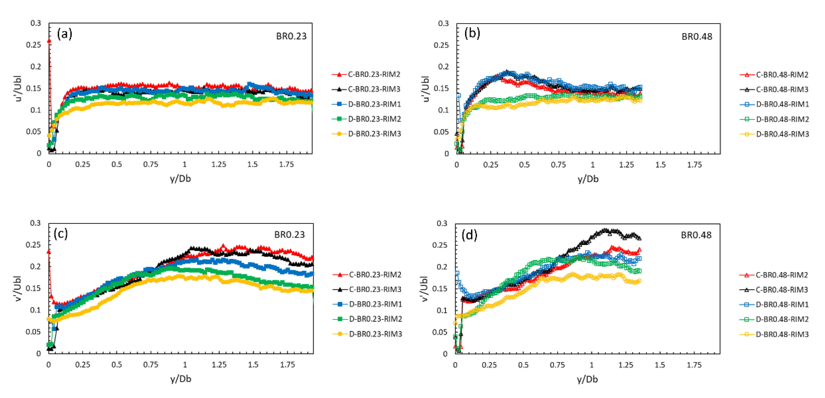
Centerline (CL) profiles of the axial and radial velocity root mean square (RMS) fluctuations are also presented in
Figure 7, to provide a picture of the turbulent structure of the studied flows.
The axial turbulence intensity levels, along the centerline, inside the RZ are nearly uniform, regardless of blockage and bluff body shape. The radial turbulence intensity component attains overall higher values with constant magnitude up to 0.5 D
b and decrease as the wake develops further downstream of the reattachment region; this is well supported by previous findings in the literature [
6]. In general, both components display almost uniform distributions along the CL with peak values dominated by regions of local anisotropy encountered in the bluff body trailing edge and the reattachment regions,
Figure 7. Finally, thicker rim disks appear to generate lower radial and axial RMS values in contrast to thinner rim disks or cones.
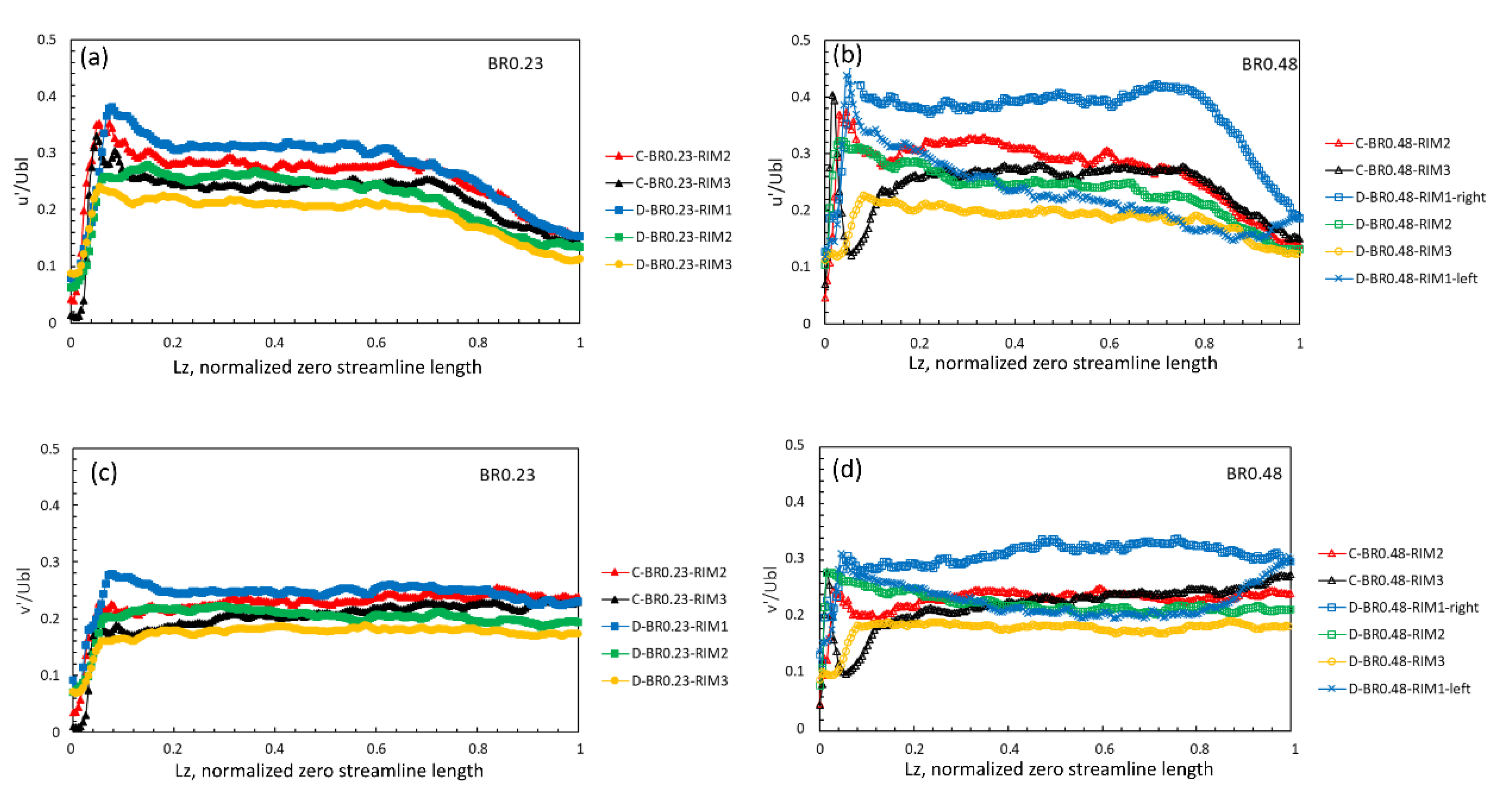
A comparison between the development of the turbulence intensity levels along the centerline,
Figure 7, and the zero streamline,
Figure 8, permits a better understanding of the interactions between the reverse zone, the externally spreading shear layer and the redevelopment zone, which extends from the reattachment point up to the axial position where the centerline axial velocity achieves its plateau.
With reference to the bubble regions designated in
Figure 9, the zero streamline on one hand follows closely the emanating shear layer in region 1, half way along the bubble, and on the other hand defines the boundary, where the flow converges toward the reattachment, in region 2. The zero streamline also coincides with peak radial turbulence intensity distributions related to local mixing signifying the entrainment activity and transport across the RZ boundary.
Initially, velocity fluctuations reach a peak, close to the baffle edge, at a distance of about 0.05–0.1 along the normalized, by the burner diameter D
b, zero streamline length (Lz), with a subsequent decay followed by a near constant value up to 0.15–0.2 Lz (region 1) and then a sudden drop toward the stagnation location (region 2),
Figure 9, [
48].
For both blockages higher velocity fluctuations, around 25% in the radial and about 35% in the axial direction, are exhibited by the thinner disks all along the dividing streamline, with the cones falling right below, around 22% and 30% respectively. Lastly, disks with RIMs 2 and 3 achieved values less than 20% for both radial and axial fluctuations.
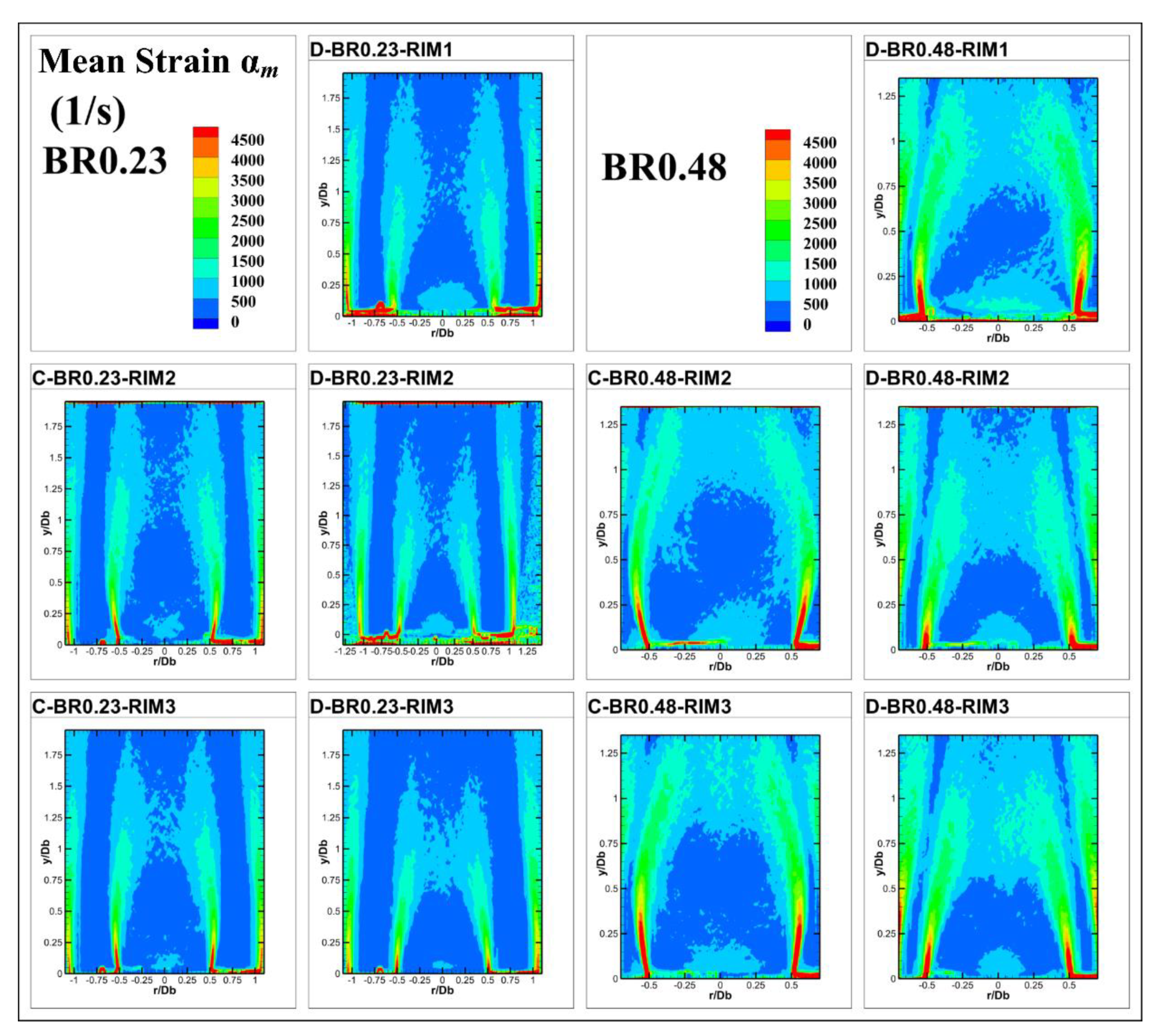
The strain rate distributions in these fuel–air premixer/flame stabilizer configurations affect drastically the flame placement and stabilization under the counterpart reacting conditions [
12,
30]. The mean or bulk strain rate (see Equation (4)) topologies have been estimated from the time averaged velocity fields, employing a central differencing scheme for the involved velocity gradients, and are shown in
Figure 10 for the ten selected baffles.
In the vicinity of the bluff body edge the mean strain rate values are higher for larger blockage cones and thinner disks than for the thicker disks and the smaller blockage baffles. This trend could be associated with the increased deflection angles and the accompanying velocity gradients close to the annular exit. A twofold increase in the blockage ratio, sustained a measurable amplification of the mean strain rate production both along the shear layers and closer to the stagnation point.
Comparing bulk strain rate production between baffle shapes, of the same blockage, suggested that the cone produced a strain rate 1.7 times higher than that of the disk. Furthermore, increasing the rim thickness by a factor of two, reduced the bulk strain by a factor of 1.7, for the disk shaped baffles.
A further contribution to the strain rate comes from the smallest turbulence scales. According to [
49] the straining by the smallest eddies can be described as the inverse of the Kolmogorov time scale. These eddies can possibly enter into the flame structure and produce the largest straining rates, possibly leading to local extinction of some inner reactions, when considering reacting configurations. Although reactions are expected to alter the specific strain values derived from an isothermal configuration, primarily due to pressure and density changes, the overall trends regarding the different baffle geometries can be usefully projected to assist in the interpretation of the stabilization behavior of different fuels and blends. The turbulent strain rate,
, has been derived from the following expressions:
where
express the Kolmogorov time scale,
is the kinematic viscosity of air,
is the dissipation rate,
is an empirical factor (approximately 0.09),
is the turbulent kinetic energy, obtained from Equation (3) and
is the integral length scale.
In the present work, the integral length scales were computed from the spatial auto correlation of the PIV data along the longitudinal direction, similar to [
12].
where
x and
y were the radial and axial positions of the point at which the integral lengths were computed. Then, the spatial autocorrelation was estimated from the following equation:
where the overbar represents ensemble averaging and
represent instantaneous axial velocity values. The autocorrelation function was executed for each cell, associated with the counterpart velocity vector, along the stream-wise direction of the measurement domain, until the “
R” parameter equaled zero. The produced results are consistent to those reported in the literature [
12]. Attention must be paid according to [
50], to the spatial measurement domain, which should be large i.e., at least six times lengthier than the integral length scale.
Examining
Figure 11, it is evident that the prominent effect of enlarging the bluff body diameter is the growth and spread of the turbulent strain rate levels along the shear layer development and close to the stagnation region. Cone shaped baffles exhibit higher values than the corresponding disks. Additionally, enlarging the rim of disk baffles substantially reduces the magnitude of the turbulent strain rate levels. Specifically, turbulent strain rate magnitude appears to be strongly affected by the rim thickness all along the shear layer development, exhibiting a 40% decrease from RIM1 to RIM3, whilst smaller variations are attained in the reattachment region, of up to 16%, for smaller blockages. Likewise, under the larger blockage conditions, rim lengthening causes a decrease of about 43% at the shear layers and in the stagnation region.
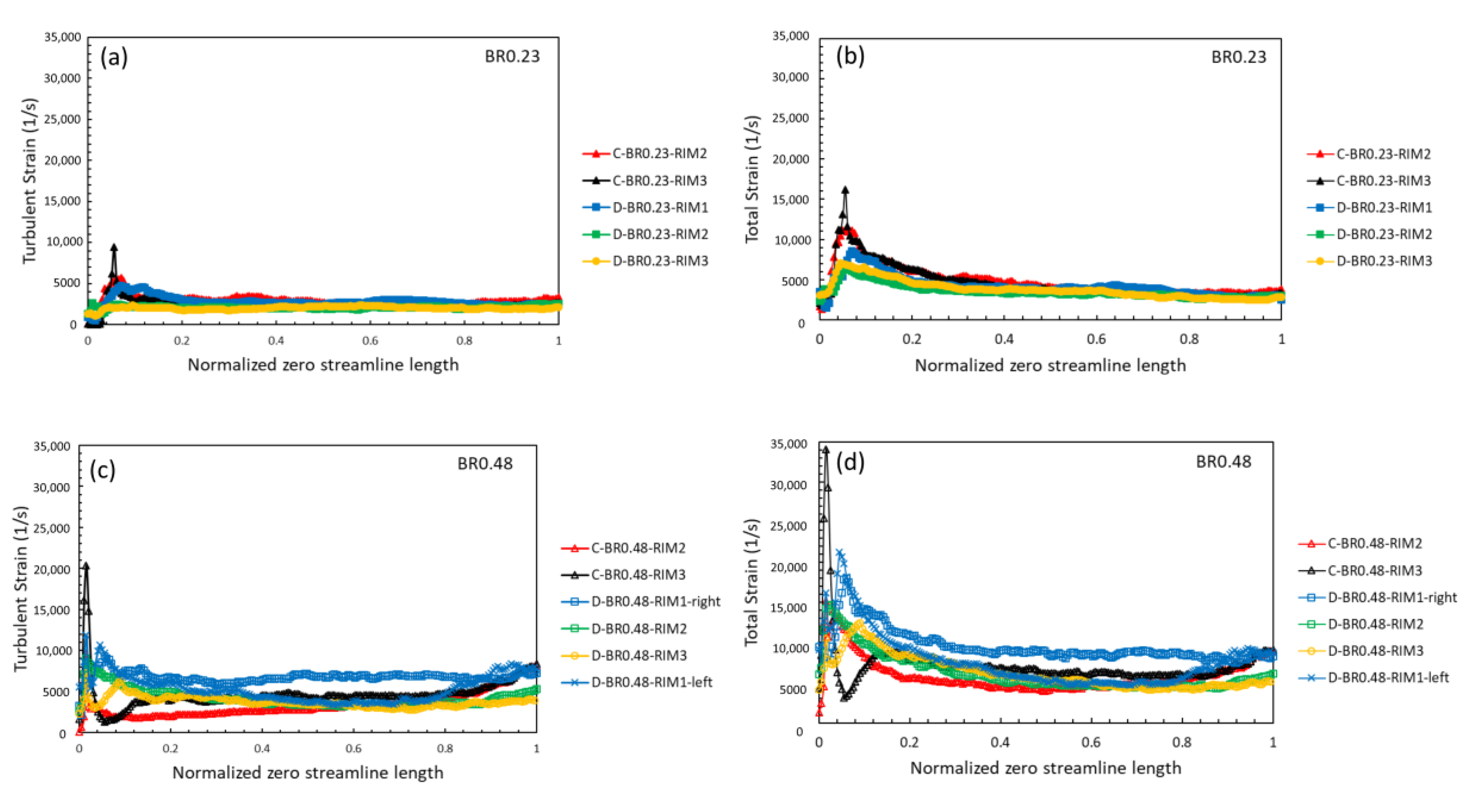
In
Figure 12, the turbulent and the total strain levels are presented. The total strain rate represents the combined contribution of the mean and turbulent strain rates, plotted along the zero-streamline boundary of the recirculation zone. The assessment of the strain rate fields in the vicinity of the toroidal shear layer, where the incoming fresh mixture is expected to be re-ignited by the recirculating combustion products, on counterpart reacting set ups, would give a rough estimation of the locally anticipated strain rates. The mean strain rate distributions would indicate regions, where the local maxima of aerodynamic strain rate levels could potentially disturb the flame by stretching and wrinkling the flame front. At the same time, the turbulent strain rate distributions could demarcate locations where the smallest turbulent scales are likely to penetrate the reacting front, forcing departures from the flamelet structure and leading to local extinction events, under reaction. Although reactions and heat release may alter, to some extent, the above deductions, projection of the present cold flow structural properties might provide a useful interlink with reacting operation.
The highest values of the turbulent and total strain rates in the initially developing region were achieved in the proximity of the bluff body rim, at Lz = 0.05–0.1, along the trailing edge. In the intermediate region, the strain values diminished monotonically and remained constant, up to the second region, where total strain either attained constant values for small blockages or slightly increased for larger blockages. For smaller blockages, maximum total strain rate values, of about 15,000 and 11,000 1/s, were estimated for C-BR0.23-RIM3 and C-BR0.23-RIM2, respectively. Then, the D-BR0.23-RIM1 case followed with levels of up to 8000 1/s. Subsequently, the strain values declined monotonically up to the reattachment, where the lowest measured values ranged from 2800 to 3200 1/s.
The distributions of the turbulent and total strain rates along the path of the zero-streamline remained qualitatively similar as the blockage of the baffles increased from 23% to 48%, with insignificant discrepancies up to the stagnation region. Quantitatively, the maximum levels of the strain rates for the larger baffles were almost twice those of the respective smaller baffles, with the maximum values for both blockages encountered closer to the lip of the burner rim. This suggests that smaller bodies, and particularly disk shaped ones, could accommodate flame stabilization of fuel-oxidizer mixtures that are less resilient to aerodynamic stretch and have lower extinction stretch values, i.e., a lean heptane–air mixture is more vulnerable to extinction due to aerodynamic stretches than a propane–air mixture, therefore a disk shaped body with a small blockage ratio seems more promising for heptane–air mixture stabilization than a larger blockage ratio cone shaped body, with the same thickness. Nevertheless, such observations can only be of a tentative nature regarding the behavior of a reacting front: flame extinction is a time dependent phenomenon and depends not only on the peak stretch exerted on the flame front but also on the probability for these stretch values to occur and on the relevant turbulent reacting front regime of the specific flame [
40].
The effect of rim thickness is more clearly depicted in
Figure 12. An increase in thickness from RIM1 to RIM2 caused total strain rate reduction of 25%, while from RIM2 to RIM3 the effect was rather unimportant with changes of only 7% for the smaller blockages,
Figure 12b,d. On the other hand, stronger variations were obtained for larger blockages due to increased rim thickness; 20–27% from RIM1 to RIM2 and 17% from RIM2 to RIM3. Trailing edge flows with greater angles raise the aerodynamic total strain, rendering ultra-lean flame stabilization challenging and particularly so for baffles with larger blockage ratios and steeper trailing edge angles. Finally, the contribution of the mean strain to the total strain rate was about 70% and seemed to be dominant in comparison to the turbulent strain, in the front section of the recirculation region (region 1), for all baffles except for disks with high blockages, whereby bulk and turbulent strain participate equally in the stabilization region.
From the investigations performed by the authors, basic characteristics of the cold flow wake such as discussed above, e.g., recirculation lengths, strain fields, turbulence levels and wake recovery rates, maintain their basic properties under combusting conditions, suffering moderate alterations of their important features [
30,
37,
39]. Similar observations have been reported by related works in the literature i.e., [
9,
45,
51]. Recirculation lengths and entrainment rates are moderately increased for ultra-lean conditions and then gradually reduced as mixtures become richer, with respect to the isothermal case [
12,
30,
51]. Strain fields follow similar trends with the location of the peak values altered due to the reacting shear layer expansion [
12,
30], while turbulence intensities gradually decrease with mixture strength due to heat release and dilatation effects. [
12,
30,
51]. The relative differences and trends, produced by the individual bluff bodies under cold flow conditions, are expected to be largely maintained under reaction and heat release, for similar inlet mixture stratification. Therefore, although cold flow studies may not be readily extrapolated to the reacting configurations, they remain of great value in elucidating expected trends and variations of counterpart reacting set ups.


