1. Introduction
Gas turbine engine diagnostic and prognostic systems aim primarily to increase flight safety and secondarily to minimize operating costs. The aforementioned aims are two sides of the same coin since the basic prerequisite for both of them is the constant monitoring of the engine operating condition in terms of life fraction consumed and life fraction remaining until the component’s replacement. In the case of modern engines, such lifing algorithms come embedded into the engine software in order to support, with useful information, the maintenance procedures. However, the user, through the user interface, only has access to high-level information like for instance a performance margin index along with a set of relevant thresholds without having any inside knowledge as to how this index is defined and what does it take into account. Given the fact that the rate of engine life consumption depends on many aspects such as the mission profile, environmental conditions (during flight and engine storage) the pilot mentality etc. such pre-programmed metrics may demonstrate a quite sizable uncertainty level. Especially in the case where, the models were developed with reference to a specific user and subsequently applied by other users operating in a completely different environment.
Let us not disregard Volponi’s (Volponi 2014) [
1] view that an “one-size-fits-all” EHM (Engine Health Management) system will not ever exist. Consequently, the right way to move forward regarding engine diagnostic and prognostic systems is to equip the engine with sensors in order to collect as many data as possible during operations and then use those data to develop tailor-made algorithms for engine fleet management.
Users shall be supported and guided by the OEMs (Original Equipment Manufacturer) to develop their own tools or alternatively adapt existing tools to their own fleet operating parameters. A less accurate life monitoring method developed based on the user’s data may prove more valuable regarding engine fleet management, than a highly sophisticated prognostic algorithm developed with reference to data sets of a different user. Additionally, tailored made engine life consumption studies based on engine recorded data and computationally efficient methodologies, may also be applied for purposes of results validation relevant to engine operating condition produced by the embedded EHM System.
Abiding to the target of developing in house engine lifing tools, HAF collects operational data in a centralized data center and conducts comparative studies in order to enrich its knowledge with very precise qualitative and quantitative metrics regarding engine fleet life consumption. This could be regarded as a database populated with a simple rule of thumb type of info build on solid, field operating data.
Comparative, rather than absolute value studies, are preferred since the material behaviour cannot be predicted accurately enough, like for instance the operating conditions to which the engine is exposed. Moreover, a user has limited access to the material properties and characteristic curves. Therefore, as mentioned in the abstract, there is always a great level of uncertainty in those calculations not regarding the measurement, (which is also present, but it is only a tiny component) but regarding the discrepancies mentioned above.
As a second step it is planned to turn those algorithms into hardware and intergrade them as separate modules into existing engines, which consists a future target for this research team. A discussion on the adaptation of the proposed Engine Lifing Method on a DEC (Distributed Engine Control) System is given at the last section of this manuscript.
The principal target of this research work as outlined below in five distinct steps, is to compare life consumption rate of the same engine acting as the propulsion system of two different versions of the same aircraft EMB-135 and EMB-145:
(i) Identify two typical missions for each aircraft. Both aircraft demonstrate repetitive flight profiles, the EMB-135 variant flies as a typical civil aircraft where as the EMB-145 flight practically consists of straight parallel legs interrupted by close turns.
(ii) Collect and process recorded flight data of the two typical flights.
(iii) Develop and use an engine model to fill in important engine parameters needed for lifing calculation calculations but not recorded by the logger.
(iv) Choose the appropriate methodology and life consumption mechanisms in order to determine respective life fractions consumed during flight.
(v) Compare the results.
2. Literature Review
Over the past years within the frame of the HAF, several studies addressing the engine usage in relation to the aircraft mission profile history, were conducted. Through those studies, new engine life consumption rate methodologies were introduced. For instance, the engine loading depending on the mission type was studied for the case of the F-16 (Templalexis et al., 2020) [
2] and the same methodology will be applied for other aircrafts as well. The ultimate goal is to make use of results to train a smart algorithm. Given the fact that aircraft loading tracking is more common than engine loading tracking, especially for the case of older aircrafts, this algorithm could be used to track engine loading based on the mission history, at a very computational cost. In a more recent study (Templalexis et al., 2021) [
3] a different approach regarding engine life consumption tracking, was followed. The engine loading limits of a certain aircraft were defined by examining the lightest and heaviest possible in terms of engine loading, missions. The study focused on the T6 aircraft but the methodology could be applied on any other aircraft provided mission history profile is available. Defining the range of engine loading, all missions could be rated regarding the engine loading within this range based on a single value of a certain loading factor. The current study addresses the specific case where an engine is installed in two different versions of a certain aircraft type, with more of less repetitive mission pattern, in order to quantify potential differences in engine life consumption rate.
According to the engine certification rules, engine lifing is conducted based on the engine’s critical parts. Critical parts are defined as those parts whose failure is likely to cause hazardous effects. Such parts are primarily the rotor discs and spacers, the combustor thin shell walls, the shafts and the casings of any rotating component which are meant to contain any raptured bit of material originated from a rotating part. As pointed out in (C.H. Tao et al., 2000) [
4] the failure caused by rotating components accounts for more than 80 per cent of the military engines. Among them, the 40 per cent of rotating components failures are brought about by the failure of rotor blades. Even if blade rapture is not considered a failure that can cause hazardous effects since engines are designed to contain the blades and retain enough shaft balance, blades remain the best engine part upon which the lifing could be based because they have the biggest probability to fail first and ground the engine and the aircraft. Moreover, despite that is not considered as a highly critical engine component, there are cases where a broken blade caused severe DoD damage putting in danger the safe completion of the mission.
Blade deterioration is classified as recoverable and non – recoverable. Recoverable in the sense that a maintenance action, can fully alleviate the blade deterioration. Blade lifing methodologies, are obviously only related to non-recoverable deterioration. Engine performance monitoring, is a prerequisite for any diagnostic, prognostic or life consumption study. However there are no clear boundaries between these three highly interrelated notions. Focusing on the etymology of the word diagnosis, it interprets to the notion of reaching the knowledge (gnosis) through the analysis of a certain set of information.
In the gas turbine engine practice, the term is used to describe the process of analysing measurable deviations of gas path thermodynamic parameters, in order to acquire knowledge regarding engine faults, like for instance blade fouling, corrosion, tip clearance gap increase etc. This approach was founded by Urban (Urban, L.A., 1972) [
5] through the introduction of linear gas path analysis. Over the following decades, it was brought to the next level by focusing on aspects like alternative mathematical formulation of the Influence Coefficient Matrix, sensor induced faults isolation, smart algorithms to automate the whole process etc. In parallel, other research groups, turned their attention into transient engine performance instead of the steady state flow solution, which has traditionally been the gas path analysis theoretical basis. (Dengji Zhou et al., 2020) [
6] intended to diagnose gas path faults by analysing how blade profile parameters are changing through time.
Another branch of diagnostics is based on mechanical loading input, rather than on gas path thermodynamic parameters’ values. Among the most common diagnostic techniques that fall in this category, are: Vibration monitoring, oil metal debris concentration, incoming air debris concentration, etc. this work is based on blade – usage based on lifing. Abdullahi (Abu O. Abdullahi et al., 2014) [
7] gives a thorough insight on such methods. Prognosis on the other hand, is the process of analysing data, in order to acquire knowledge about a certain state that comes in force during the future. The main difference with diagnosis is that the state is not currently valid, as it is in the case of diagnosis, and therefore one does not have the option to valid his result in statunascendi. For the case of gas turbine engines, all the above-mentioned methodologies to conduct a diagnosis could be projected to the future to prognose the future engine state. The ultimate knowledge is being sought when gas turbine engine prognostics are applied, is to define the point in future that the engine will become non usable, either due to a catastrophic failure or due to unaffordable operating cost.
The aforementioned prognostic and diagnostic methods, consist the theoretical basis of various methods which support the corresponding engine diagnostic and prognostic tools. Such tools, may use more than one method in a complementary manner to produce more reliable output. Then, those computational tools are turned into algorithms which equip internal diagnostic modules accompanying the engine which include all the necessary software and hardware components, taking as input engine operating information and providing the user directly with the knowledge of diagnostic or/and prognostic nature. Those EHM modules used to be operating off-board keeping just the sensors and the data recorders on-board. Module architectures are gradually shifting towards more and more on board features.
This study focuses on gas turbine lifing, targeting in specific, among all engine LLP, the first stage of turbine rotor, for the reasons explained in the introductory section. There are three main life consuming mechanisms for blades: Corrosion, LCF and creep and potential interactions between them. Regarding creep failure mechanism, most of the life estimation methods are related to the Larson Miller parameter method. The later requires as an input the blade thermomechanical loading history. Sanaye (Sanaye Sepehr et al., 2020) [
8] give in their introduction a comprehensive review of recent relevant research. Researchers, differentiate themselves, in the way blade thermomechanical loading is calculated and also regarding ways engine recorded operating history is taken into account. Regarding LCF there are several lifing approaches which are based on material’s theory. A relevant categorization is given by Christ (Christ HJJA et al., 2003) [
9]. In this research, given the fact that the total number of cycles are calculated by the manufacturer, we are only confined in counting the loading cycles. The most commonly used method for cycle counting is the rainflow method, with several variants proposed. Chachurski (R. Chachurski et al., 2011) [
10] give an extensive literature review on LCF cycle counting.
3. Materials and Methods
3.1. Aircraft-Powerplant Description
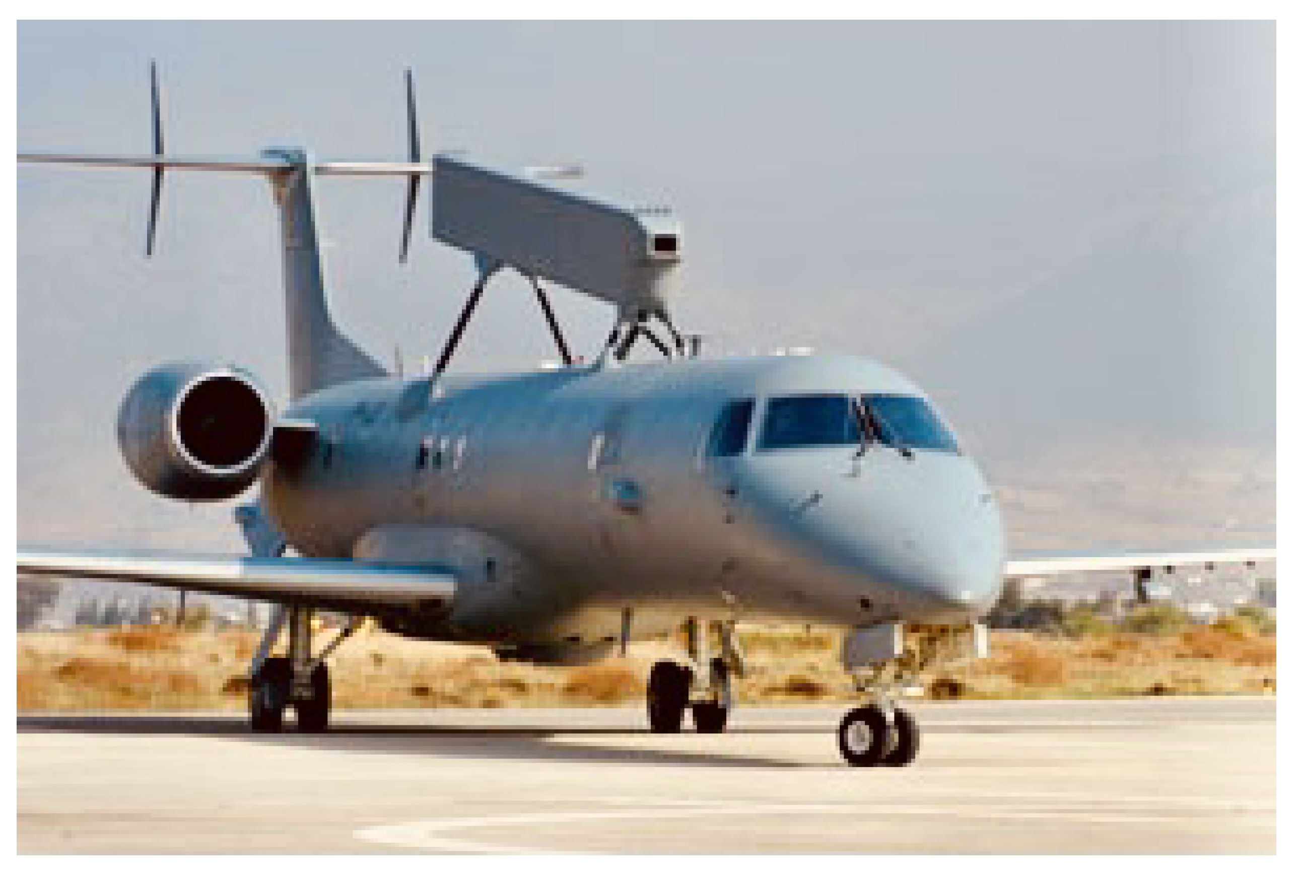
This comparative study will be conducted on the Erieye EMB-145 AEW&C (Airborne Early Warning and Control),
Figure 1 and (VIP) EMB-135LR,
Figure 2 versions of the same aircraft, powered by the RR AE 3007A1P turbofan engine. Both aircraft are operated by the HAF, the first as a VIP passenger civil aircraft used mainly to cover government transportation needs and the second for missions as intended by its role.
Table 1 below, summarizes the basic characteristics of the two aircraft:
The Rolls-Royce AE 3007 is a two shaft, turbofan engine. The low-pressure spool connects the single stage fan with the 3-stage LPT (Low Pressure Turbine) and the high-pressure spool links the 14-stage HPC (High Pressure Compressor) to the 2-stage HPT (High Pressure Turbine). It has an annular combustion chamber and also a forced core-to-bypass mixer at the engine exhaust area.
Table 2 below, summarizes the basic characteristics of RR AE3007 engine.
Two typical aircraft missions were considered. Missions were designed by pilots (one for each aircraft) who operate those aircraft. They were asked to prescribe the whole flight, in terms of distinct flight legs defining altitude, PLA (Power Lever Angle), speed, etc. values which were matched against recordings extracted from engine log files. The reason for examining two mock missions is first, to avoid complex procedures regarding permission for publication and secondly, and most importantly the missions needed to be as representative as possible of the aircraft usage profile and the best way to achieve that other than analysing all recorded missions and define a median, is to take advantage of the pilots experience. The engine recorder tracks rotational speeds (needed for the stress calculation) and inter turbine gas temperatures. For the proper blade temperature calculation however, the compressor outlet temperature (acts as a blade coolant) and turbine inlet temperatures are also needed. Instead of a simple 1-D hand calculation, the GasTurb V10 software was incorporated to model the engine and calculate more accurately the required temperatures, in order to match the closest possible HP spool rotational speed and interturbine temperature, where in all cases difference did not exceed 4 per cent deviation from recorded values.
All off-design points for both missions were simulated and trimmed accordingly, in terms of assumed values for efficiencies, in order to match the closest possible HP spool rotational speed and interturbine temperature.
Table 3 summarizes the efficiency values used for the engine model:
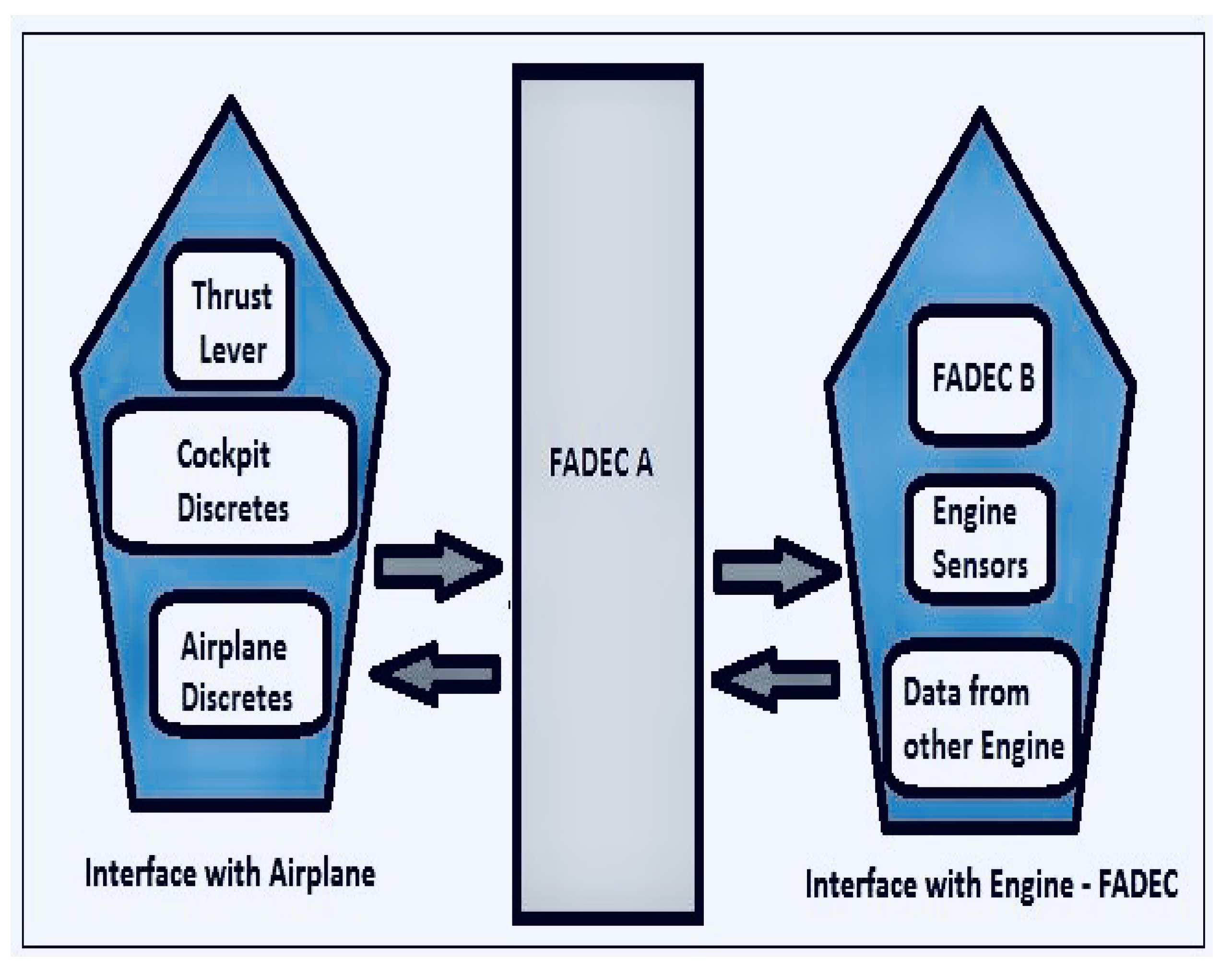
The Rolls-Royce AE 3007 engine uses an electronic control system based on two Full Authority Digital Electronic Controls (FADECs), named FADEC A and FADEC B, that control the engine, as shown in the
Figure 3. These FADECs interface with the engine, air frame and flight deck, as all signals between each FADEC and its respective engine and between the FADECs and the airplane are completely redundant and isolated. This allows either A or B FADEC to control the engine independently, as shown in the below figure-schematic.
The engine control system performs two categories of functions: thrust management and engine control. Thrust management logic interfaces with the airframe and schedules a corrected thrust based on air data and cockpit inputs. The fan speed request is passed to the engine control logic, which controls the engine fuel flow and Compressor Variable Geometry (CVG) in response to the measured parameters in order to attain the required engine response.
All these parameters are stored in FADEC as data, which are collected by the technicians of the Squadron in which the EMBs are maintained, at the end of each flying day, following the instructions of the OEM. The collected data is sent monthly to ETHM for processing and evaluation of the fleet operational condition, using EHM methodologies.
3.2. Mission Definition
Aircraft Erieye EMB-145 AEW&C is an air command platform, able to support air and naval military operations. The basic flight pattern of this aircraft after having climbed to its operating height, is to scan a certain area doing repeating straight cruise legs interrupted by close turns. During climb there is a maximum climb rate limitation due to the antenna structural limit. Other limitations during flight are related to the aircraft AOA and the optimum antenna operation.
Table 4 summarizes typical settings for EMB-145 flight legs that can be encountered during a mission.
Aircraft EMB-135 LR (VIP) is used as a transporter with maximum passenger capacity of 32 persons. PLA settings for flight legs that can be encountered during a mission, are summarized in
Table 5. Main differences with the Erieye version are the following:
It carries no radar which makes it lighter and needing less power for a certain manoeuvre.
It has no specific (antenna) structural limitations, therefore climb rate does not need to be controlled.
It executes straight cruise legs from Point A to Point B without being interrupted by repeating turns.
3.3. Low Cycle Fatigue and Creep Calculations
3.3.1. Low Cycle Fatigue Counting
The engine, as operated by the HAF, does not have an LCF cycle counter installed. An overly broad approach is to count one cycle each time the engine completes a full start-stop cycle. However for this study that would be an oversimplification since it is known that when flying the EMB-145 aircraft version, there are much more throttle adjustments that need to be done. Consequently, the rain flow cycle counting method as applied in (Templalexis et al., 2020) [
2] and in (M. Musallam et al., 2012) [
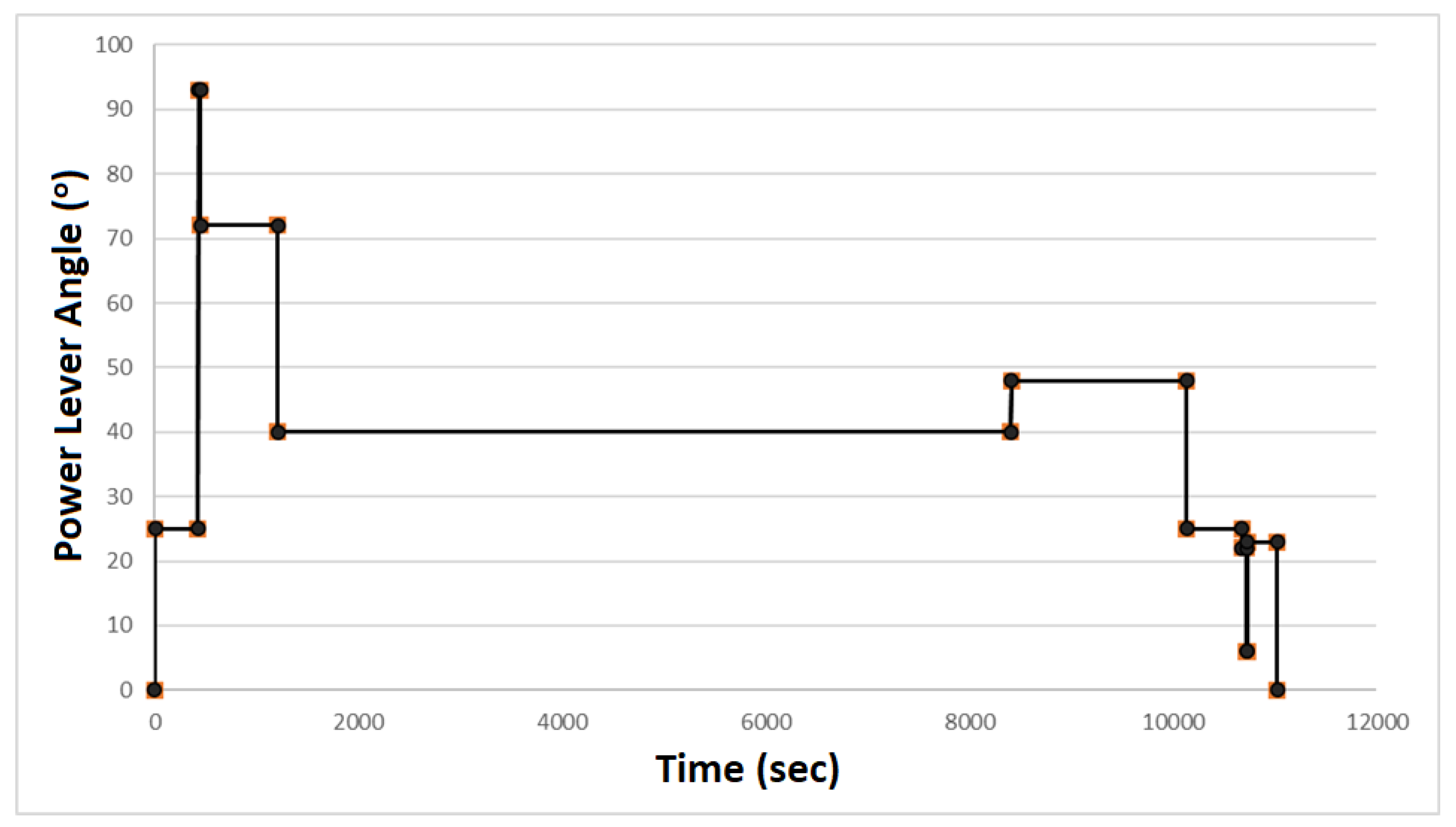
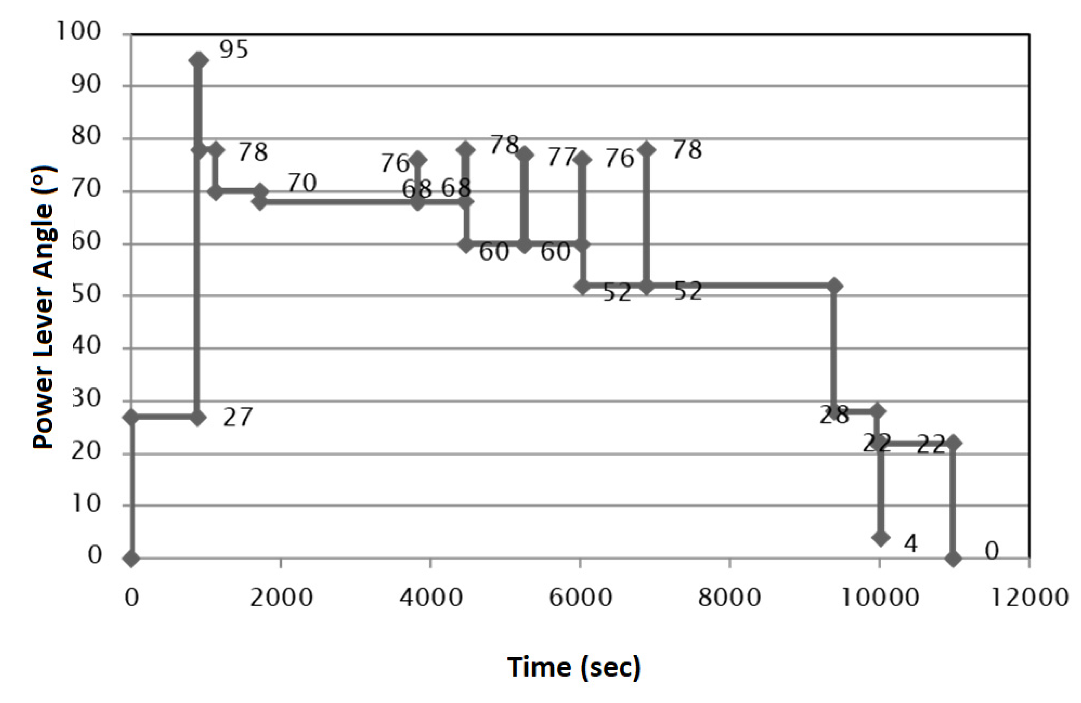
13] was applied to the High Pressure (HP) spool, in order to have a more accurate recording of the engine cycles. The stress as a parameter was substituted by the PLA, which is constantly recorded during flight and it is directly proportional to the stress level developed during operation. Half and full cycles are counted. Regarding stress only normal components were taken into account. Under the aforementioned assumptions, the number of cycles counted would be the same regardless of the load handle considered (PLA or Stress). PLA was preferred because it is a direct output from the flight recorder.
Figure 4 and
Figure 5 demonstrate the PLA time history for the two flights addressed.
3.3.2. Creep Calculation
Creep damage is related to the level of thermomechanical loading it is subjected. The method that is followed to determine the life consumption due to creep, is the Larson - Miller Parameter (LMP) method (Larson Frank et al., 1952) [
14]. According to this method the creep life fraction is determined based on the stress and temperature levels the blade operates. Life fraction consumed during the time spent at a certain operating condition is calculated from Equation (
1):
where, the time-to-fraction (
) given to the denominator is calculated from Equation (
2), as follows:
The numerator expresses the time spent at a certain operating condition. Equation (
2) needs as inputs, the LMP value as well as the blade metal temperature (
). The blade material used for the turbine rotor blades of the AE3007A engine, is the CMXS 4. For a certain stress level, the LMP can be read from the material master curve as published in Wahl et al., 2014 [
15].
Only the normal stress component is accounted, the one due to the centrifugal force. Additional normal stress components, appearing due to blade bending, are neglected. Stress is calculated at blade roots, the most critical section along the blade span. Equation (
3) expresses the normal stress due to the centrifugal force applied to the blade of mass mb rotating at a speed
(rad/s). The geometrical parameters needed for the calculation were the cross-sectional area at blade root and the distance of the blade root section from the axis of symmetry, values that were directly measured on the engine. The blade was weighted to determine its mass.
Finally, blade temperature is needed to determine the time-to-fraction based on Equation (
1) is calculated from Equation (
4)
The gas temperature () at the exit of the combustion chamber, is calculated running the GasTurb engine model. The cooling medium is air bled from compressor exit. Its temperature () is a direct output from the engine model, since it equals to the gas temperature at the exit of the compressor. The cooling efficiency () for the engine model was considered equal to 50 per cent, a typical value for such a cooling system.
4. Life Consumption
The methodology for the (HPT) blade lifing is presented in (Templalexis et al., 2020) [
2]. A brief outline is also given here. The total life consumption (
) is computed by summing the life fraction components attributed to LCF (
) and to creep (
) according to the Equation (
5).
It should be mentioned that Equation (
5) is applied here to compare the engine loading for the two missions examined. Regarding engine maintenance, a flag shall rise when any of these life fractions exceeds 100 per cent due to creep or LCF. Interaction between the two failure modes can only make things worse for the engine, that is increase the engine life consumption rate and this becomes more prominent at higher temperatures. Therefore, given the fact that the engine within EMB-145 records on average higher temperature values, the life consumption rate gap of the engine when installed in those two different aircraft versions, is expected to be even wider.
The first term on the Right Hand Side (RHS), expresses the total life consumed during a mission, attributed to creep. During the flight, Equation (
6)
sums up the ith fractions of creep Life Fraction (
) consumed during the
n-flight legs.
The second term on the RHS of Equation (
5) expresses the life fraction consumed due to LCF (
) defined in Equation (
7), where the number of Total Accumulated Cycles (
) during a flight is divided by the number of Total Accumulated Cycles would occur in the Time period Between two Overhauls (
):
where, the denominator equals to 2400 cycles.
5. Results
Low Cycle Fatigue
The following number of cycles were counted. For a typical EMB-135 mission 10 half cycles, equal to 5 full cycles were accumulated and for a typical EMB-145 mission, 12 half cycles and 4 full cycles were recorded, which sum up to a total of 10 full cycles.
The corresponding life fractions consumed are:
Regarding creep life consumption,
Table 6 and
Table 7 contain the values of the main parameters which led to the summarise results of corresponding life fractions that contained in
Table 8.
The corresponding life fractions were:
Consequently, total life fractions for missions of the EMB-135 and EMB-145 were:
6. Discussion on Adaptation of the Proposed Engine Lifing Method on a DEC Control System
FADEC has been the standard for control of gas turbine aero-engines for several decades, as explained by Jonathan et al., in (Kratz et al., 2018) [
16]. This centralized architecture results in a dual-redundant control system with point-to-point analog signaling topology that connects the FADEC to the engines sensors and actuators, a process leading to a hindrance to aircraft performance due to the addition of redundant connections and components, as it adds weight to the system through the wires and protective harnesses. As it is explained in the aforementioned, DEC is a response to the limitations of the current control approach, and will enable new advancements and contributors toward improved engine performance, efficient, and safety.
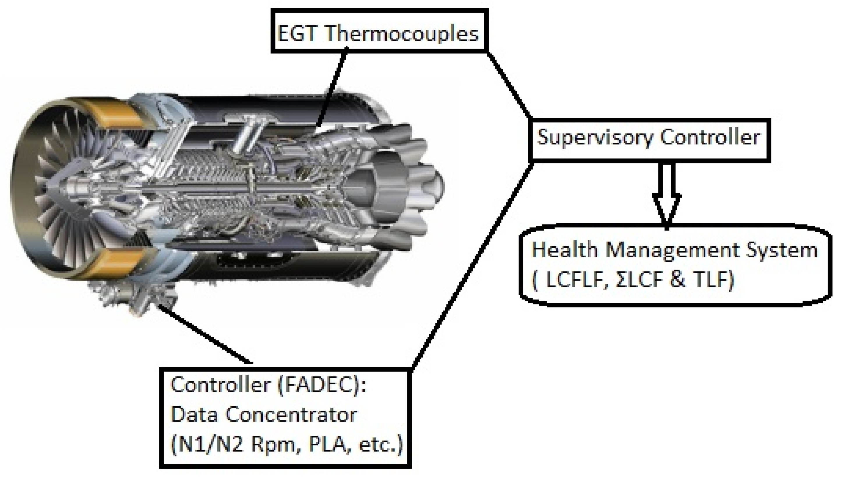
Such a DEC application constitutes the Life Extending Control (LEC) as presented in (Ten-Huei Guo, 2001) [
17]. The proposed control architecture introduced the idea of a highest “Supervisory Level” controller, which modes are determined according to the external commands and the status of engine health and performance conditions, in order to combine existing continuous monitoring with discrete decision—making processes.
Authors suggested the development of such adaptive—based controls which can be coupled through the supervisory control to share information with health management and integrated power. This should includes a DEC like that presented in (Seitz et al., 2016) [
18], which will operate independently of the existing FADECs and will process—store the collected data on a separate basis, as shown in the
Figure 6.
7. Conclusions
The engine life consumption of two Embraer aircraft variants was studied. Two typical missions were constructed based on engine recorded data and pilot experience on the aircraft type. According to the results, loading due to LCF is double for the case of the EMB-145 variant. Life consumption due to creep is much higher, which is expected due to the higher on average, Power Lever Angle (PLA) angles applied. One could practically assume that life consumption due to creep for the EMB-135 usage profile is almost negligible compared to the rest of the life fractions.
The study also shows that the engine, as an EMB-145 aircraft propulsion system, has to be closely monitored because of the increased life consumption rate it experiences on that frame. In case the engine has the same maintenance schedule for both aircraft, then a more detailed life consumption study would be useful in order to find out how much margin is left to the EMB-135 critical components before they are replaced.
At the end, an architecture for the development of a DEC it is proposed through this study, which can be coupled through the supervisory control to share information with health management and integrated power as shown in the above figure.


