Communication

Architecture of Distributed Control System for Gearbox-Free More Electric Turbofan Engine

1
Board, JSC ‘FED’, 132, Sumska St., 61023 Kharkiv, Ukraine
2
Department of the Engine Design, National Aerospace University “Kharkiv Aviation Institute”, 17, Chkalova St., 61070 Kharkiv, Ukraine
3
Department of Research, JSC ‘FED’, 132, Sumska St., 61023 Kharkiv, Ukraine
4
Department of Functional Bureau at Research, JSC ‘FED’, 132, Sumska St., 61023 Kharkiv, Ukraine
*
Author to whom correspondence should be addressed.
Aerospace 2021, 8(11), 316; https://doi.org/10.3390/aerospace8110316
Submission received: 1 September 2021 / Revised: 28 September 2021 / Accepted: 30 September 2021 / Published: 24 October 2021
(This article belongs to the Special Issue Technologies for Future Distributed Engine Control Systems)

Abstract

:
This article presents the development of the electric turbofan engine in distributed architecture with a design thrust in the range of 3 to 7.5 and from 7.5 to 30 kN for small and medium-sized unmanned aerial vehicles. The engine subsystems are considered as separate smart modules with a built-in control system, exchanging data via a digital channel with the central engine control and diagnostics unit. The key smart engine units are combined in the following subsystems: starter and turbine generators, oil pumps, actuator of guide vanes, fuel pumps, fuel metering unit, control and diagnostic unit. All pumps and guide vane actuator are electrically driven. Control and monitoring signals are transmitted via a digital bus. Functional and reliability analysis and the technical configuration design of each subsystem are presented. Based on analysis of the architecture of distributed control systems for a gearbox-free electric engine, different configurations of described subsystems are proposed.

1. Introduction

The traditional architecture of a turbofan engine provides an accessory gearbox that transfers mechanical power from the engine shaft to the units: starter, generator, fuel and oil pumps, as well as other auxiliary units. To control the mechanisms of the engines (guide vanes and air bleed valves), hydraulic servo actuators are used, driven by the high pressure of the fuel taken from the pump outlet [1]. Significant progress in power electronics, as well as increasing requirements for maintainability, survivability, the possibility of modernization and environmental compatibility of engines and power-to-weight ratio of aircraft lead to the need of a more electric engine [2,3,4,5]. It leads in terms of the design of power drives to replacing traditional hydro-mechanical drives with electric ones.
At the moment, the engine developers are not ready for the full application of a more electric engine concept. The transition occurs stepwise. As an example, consider the eAPU Safran auxiliary power unit, which uses an electrically driven fuel metering pump, but all other units are still located on the gearbox [6].
JSC «FED» is the leading Ukrainian enterprise in research and development, serial production, maintenance, and overhaul of various types of components for aircraft, helicopters, unmanned aerial vehicles (UAV) and space vehicles. In close cooperation with the enterprise-developers of engines, FED developed the first generation of electrically driven units [7,8] more than 20 years ago (Figure 1) and since then has been modernizing the implemented technical solutions. This made it possible to ensure the functioning of the entire fuel system without the use of mechanical drives from the engine. Electrically driven metering pumps for small UAVs are produced in series.
It is rational that the development of the more electric engine concept should be started on unmanned aircraft. The collection of statistics of the electrically driven units operation on such aircraft will increase the reliability and optimize the technical solutions to the level of civil aviation.
Currently, turbofan engines with a gearbox that transfers torque from the engine shaft to the starter-generator are the most widely used for high power unmanned aerial vehicles. This configuration provides high reliability of the engine, but it has a large number of mechanical components and parts, which complicates maintenance and increases its cost.
A promising approach is the use of a more electric gearbox-free engine and a distributed modular architecture for unmanned aerial vehicles. This will reduce the weight and overall dimensions, the number of modules in the engine and simplify their maintenance, development and modernization [9,10,11]. To maintain the required level of engine reliability with an elevated failures probability of power electronics components, it is necessary to back up the unit’s drives, their power and control modules and to ensure their extended autonomy.
Based on the global trends in the field of aircraft engines, JSC “FED” has begun work on the development of architecture and units for more electric turbofan engines of small and medium-sized UAVs. Using standard principles in the design of systems and units (for example, in accordance with ARP4754): Preliminary System Safety Assessment (PSSA), Functional Hazard Analysis (FHA), Fault Tree Analysis (FTA), functional analysis was carried out, and its results enabled us to select the optimal system architecture.
The article presents results of developments on more electric turbofan engine distributed architecture with a design thrust of about 3 to 7.5 and from 7.5 to 30 kN (for small and medium power UAV engines). Each of the engine subsystems is a separate smart module with a built-in control system that exchanges data via a digital bus with the central engine control and diagnostics unit (Figure 2 and Figure 3).
Currently, there is no mature concept and technology of distributed architecture for a more electric engine due to the difficulty of ensuring design reliability using simple solutions [9]. Only partial solutions have been implemented in various forms. This area requires detailed analysis and the search for optimal solutions.
The main smart engine units are the following: starter (SG) and turbine generators (G) with power control units (PCU), oil pump drives, guide vanes actuator (GVA), fuel pump drives, fuel metering units (FMU), and flight control computers (FCC). All pumps and guide vane units are electrically driven. The supply voltage is 270 VDC. Control and monitoring signals are transmitted via a digital bus by the full authority digital engine control system (FADEC).
Energy generation and engine start are provided by one (for small UAV) or two (for middle-size UAV) electric machines: starter-generator and turbine generator. Both electric machines are driven by the engine shafts without using a gearbox. The starter-generator is connected to the high-pressure compressor shaft, while the turbine generator is connected to the low pressure turbine shaft and is located inside thermal protective casing.
The paper summarizes the JSC FED research results obtained as a part of work on the concept of a more electric engine.

2. Fields of Interest Requiring Investigation

For electrical machines (starter-generator and turbine generator), the key issue is to ensure the required level of reliability, taking into account possible malfunctions, as well as ensuring the reliability of the generator placed in an area of high temperature and vibration.
In the case of oil pumps, the critical issue is to ensure redundancy using the same pumping units, since the oil pump is multi-sectional. For electromechanical actuating systems, it is difficult to provide redundancy in case of a jam, as well as the necessary cooling.

3. Methods and Tools of Investigation

FED provides a full-cycle development for aircraft engine units (SG and G with PCU, oil pump drives, GVA, fuel pump drives, FMU, and FCC), which includes design, manufacturing, and testing. Cooperation with the developers and manufacturers of the engine makes it possible to test the units in real operating conditions. At the design stage, widely known and approved analytical and finite element analysis methods [12] are used in the areas of functional analysis, strength analysis, mathematical modeling and reliability analysis.

4. Results

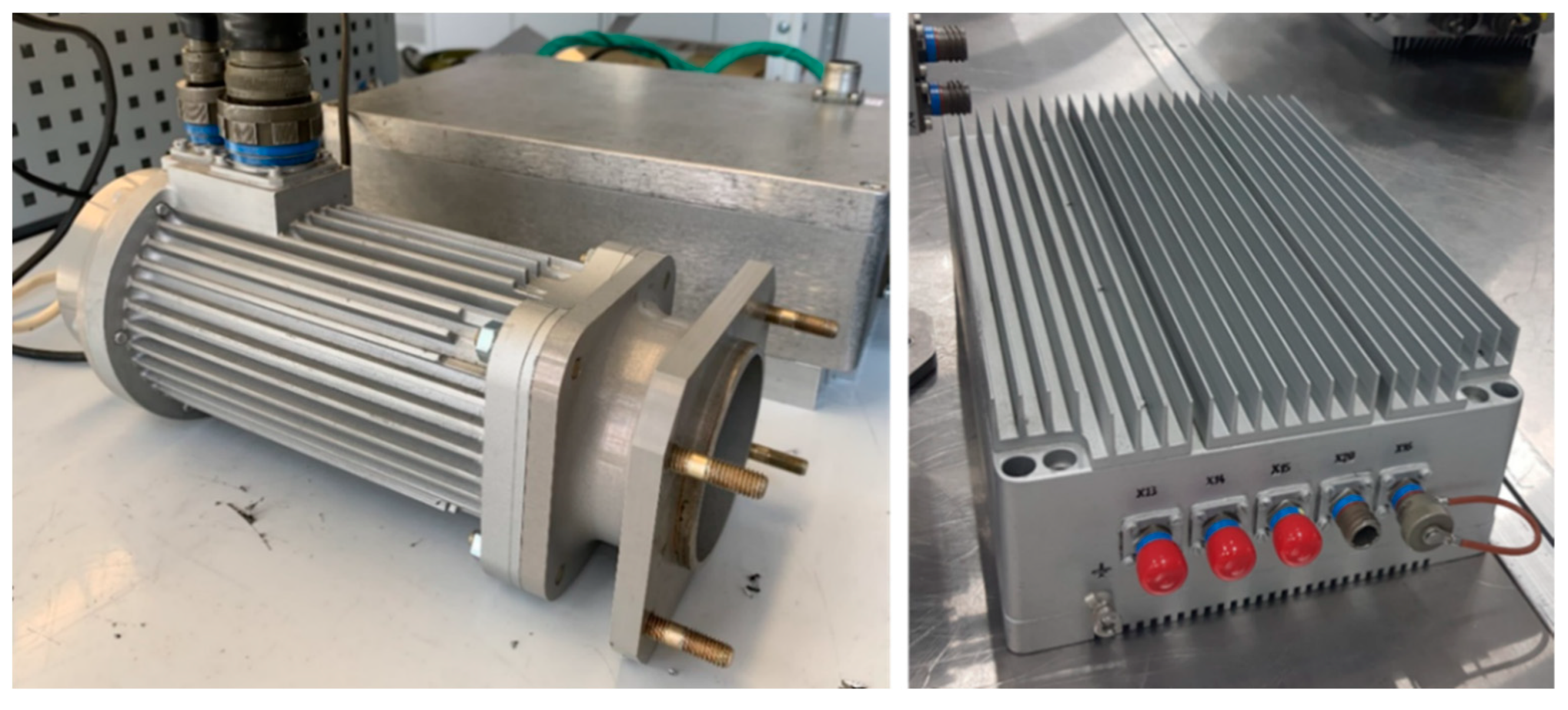
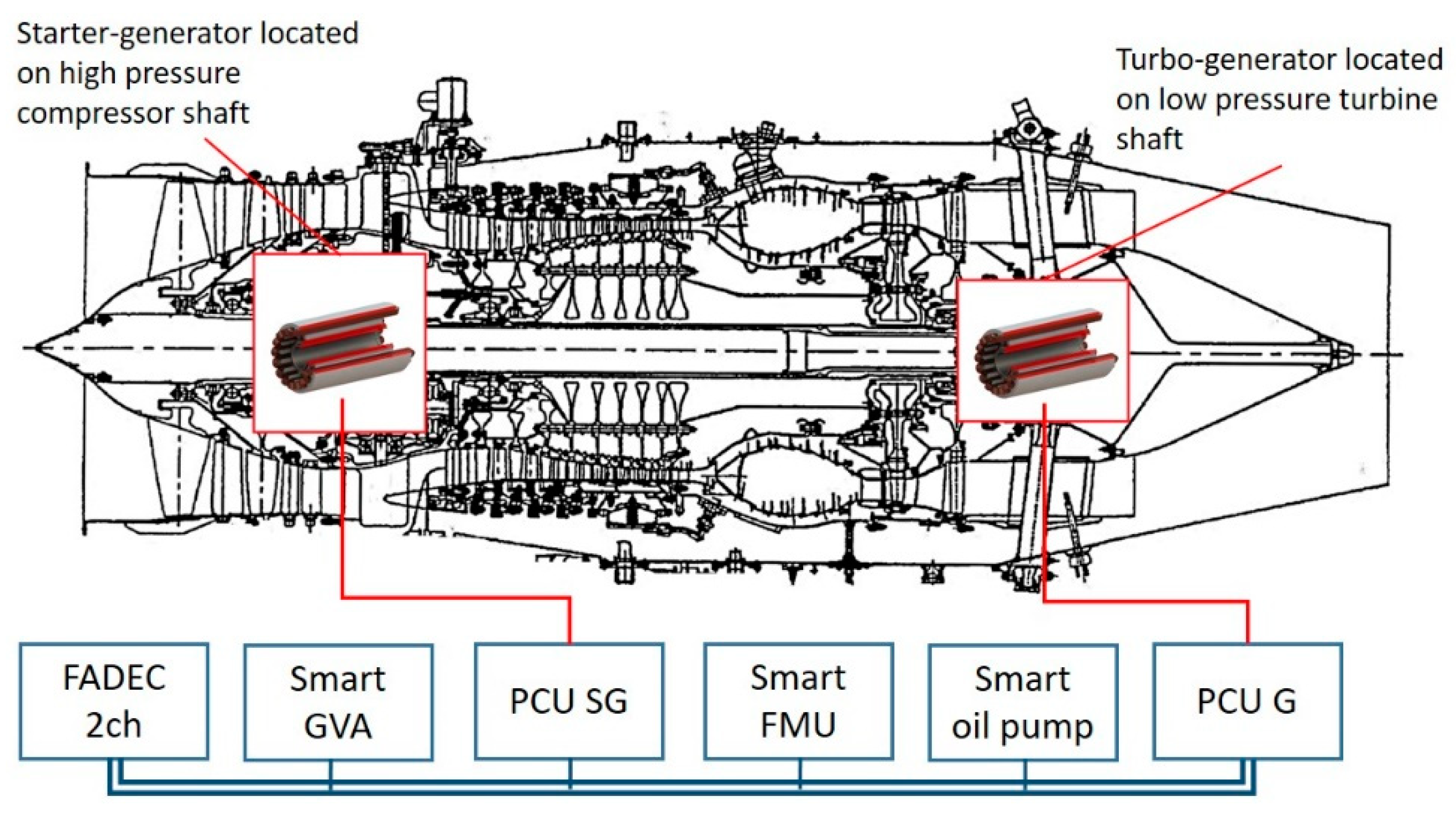
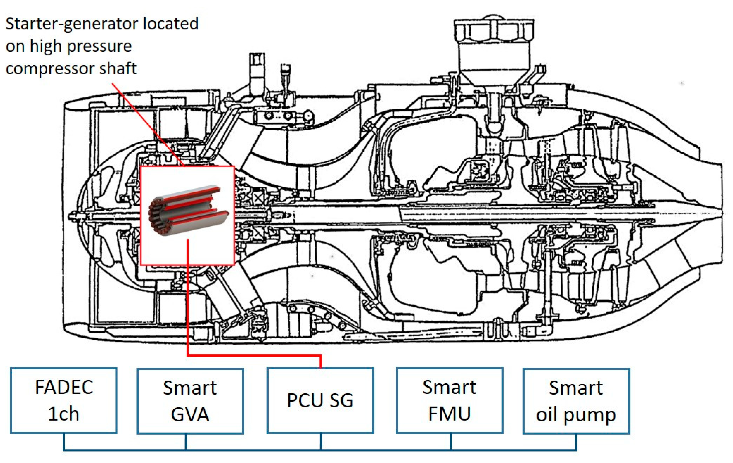
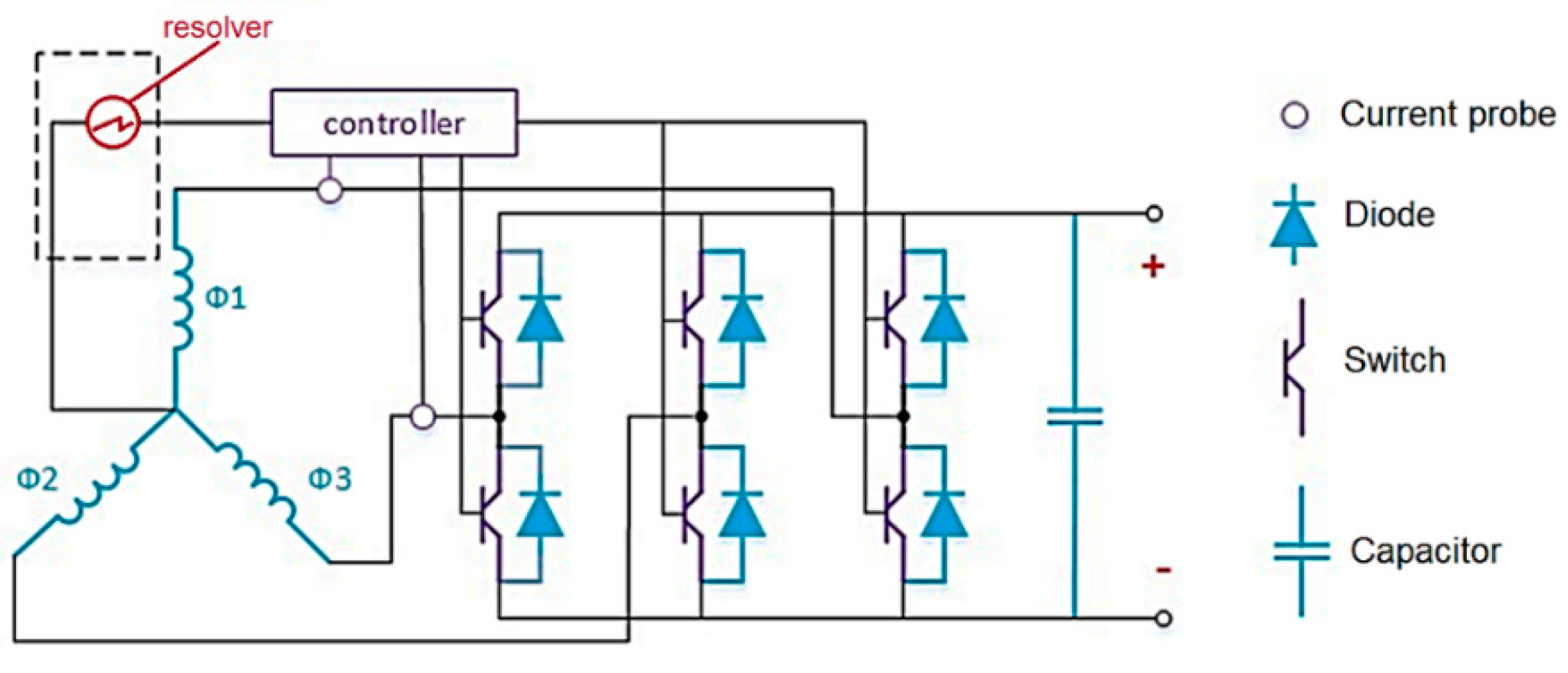
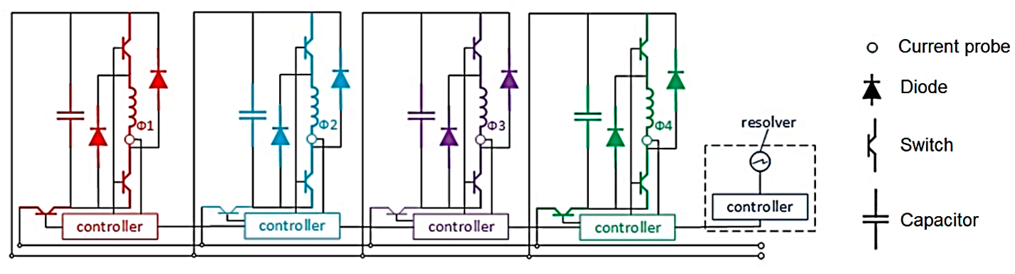
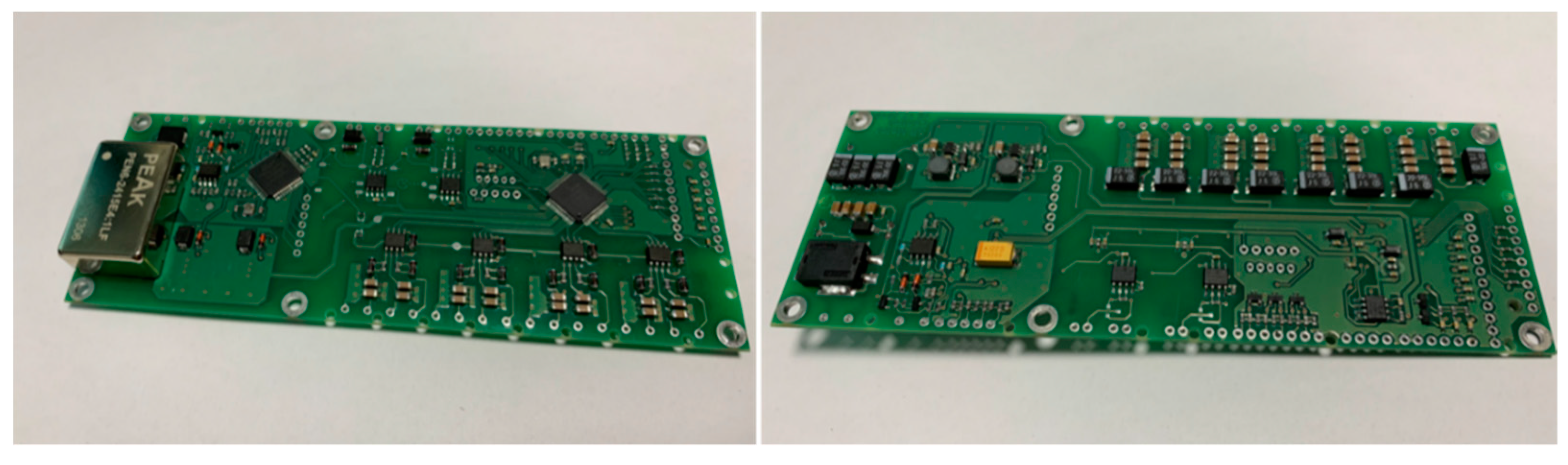
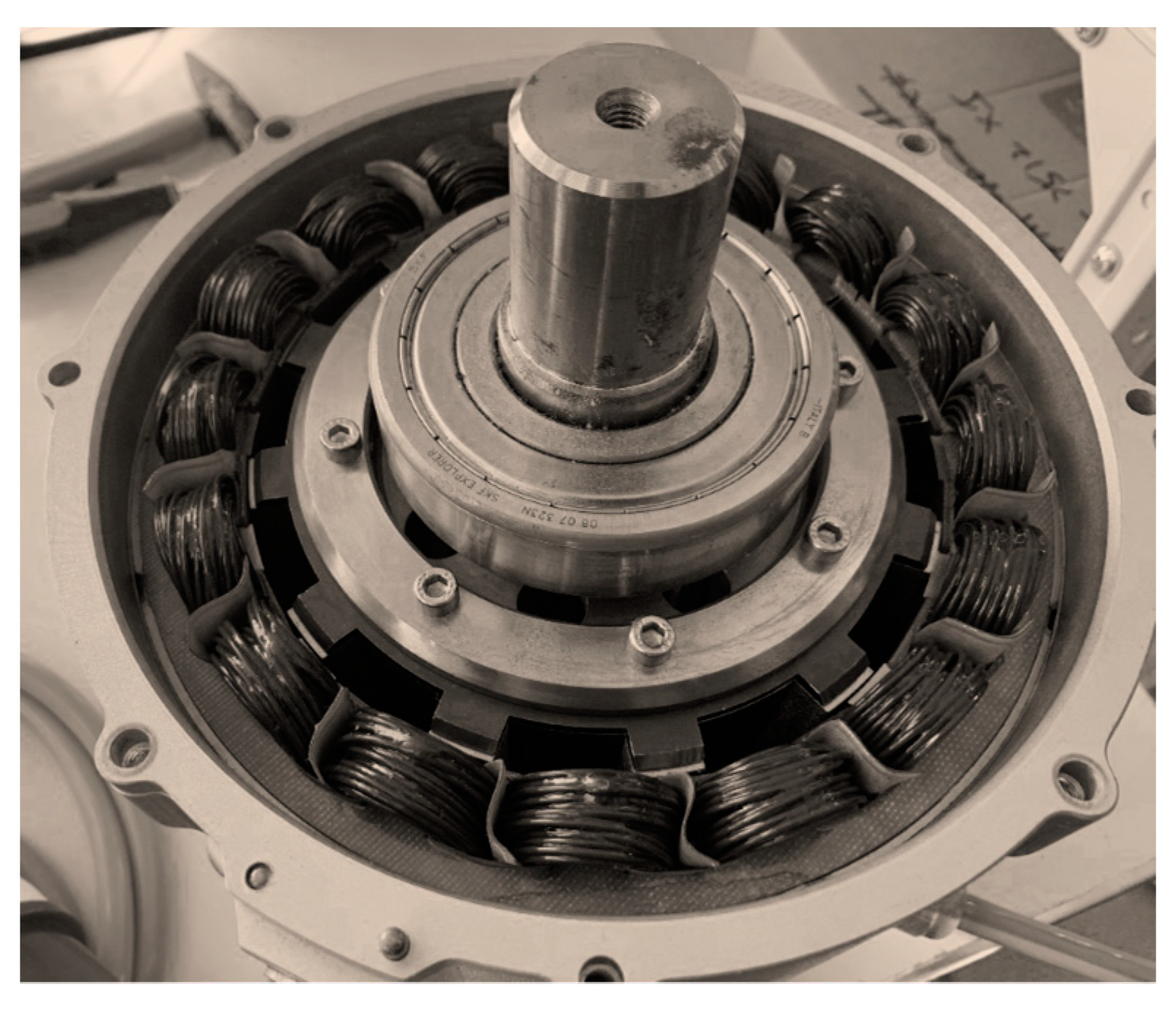
4.1. Starter and Turbine Generators

Traditionally, synchronous generators with rotor excitation (Wound-Field Synchronous Machine) are used as generators on aircraft engines [13,14]. It is a proven and reliable system; however, it has a number of disadvantages that do not allow for increasing its specific characteristics and meeting the requirements of modern and advanced power generation systems on board of the aircraft. The complex design of the rotor with rectifier diodes placed on it limits the generator rotation frequency by the criterion of mechanical strength at the level of 20,000–24,000 rpm [14]. The presence of brushes or diodes reduces the mean (operating) time between failures (MTBF) of the generator, and complicates maintenance and repairability. Asynchronous electrical machines were not considered in the analysis due to their low efficiency and specific electrical characteristics. Two types of electrical machines are considered as alternatives to synchronous generators: the permanent magnet synchronous electric machine (PMSM) and the switch reluctance electric machine (SRM) [15,16,17,18]. Three phase PMSM and four phase SRM, each with its own advantages and disadvantages, are reviewed for use as engine electric machines [19,20,21,22,23,24].
The use of PMSM with NbFeB magnets allows for the obtaining of the highest energy characteristics. There are two machine operation modes: energy generation of 270 VDC during switch control (full serviceability of the controller and all power components are required) and energy generation at an alternative mode according to the natural characteristics of the electric machine (diode serviceability and absence of short circuits are required). While designing the PMSM machines, it is necessary to take into account the need to prevent overheating of the rotor, and to eliminate shock loads to minimize degradation of the magnets’ properties during operation. It is also necessary to take into account that a short circuit can lead to the occurrence of a braking torque on electrical machines, which can exceed the maximum operating torque, with significant heat generation in the electrical machine and, possibly, the electrical unit.
When using SRM, only a 270 VDC generation mode is possible. Failure of power components or a short circuit in one of the phases does not lead to a complete failure of the electric machine, but to the disconnection of the isolated power generation control system in this phase and, as a consequence, to a partial decrease in the generated power. With short circuits, there is no additional braking torque on the rotor. The rotor and stator of the electric machine have a simple design, a wide range of operating temperatures and high reliability.
Losses in the rotor and stator bodies of SRM electric machines increase with a frequency rise less intensively than in PMSM machines. This happens because of a decrease in the level of magnetic induction with an increase in the rotation frequency in proportion to the current drop in phases in the absence of permanent magnets on the rotor. This property, along with the mechanical strength of the rotor, is the advantage of SRM over PMSM at high speeds.
The schemes of electric machines’ control systems have been developed, taking into account the required system reliability (Figure 4 and Figure 5).
Based on special aspects of gas turbine engine operation such as high temperature, vibrations, the ratio of torques on the shaft in the starter and generator modes (rotation speeds in the starter and generator modes during cruise flight may differ several times), a critical analysis of electric machines has been performed based on PMSM and SRM. Power supply systems, redundancy methods, overload conditions, types of cooling and reliability were analyzed as well.
Considered parameters of electrical machines for SG and G are shown in Table 1.
Comparative functional analysis was carried out using both analytical and finite element methods. The results showed that with the same energy characteristics, the use of PMSM electric machines provides a weight gain of 27% for SG and 8% for G.
Based on the analysis, the SRM type of electric machines was chosen as a basic and the most prospective solution due to high reliability, vibration, temperature resistance and the ability to provide free rotation mode in case of failure. The use of PMSM electrical machines causes increased risks during operation, despite the highest efficiency factors and specific performance.
For experimental testing of SRM electrical machines, electronic units, electrical machines and control algorithms were developed and manufactured (Figure 6 and Figure 7).
An adaptive sensorless control system was developed and optimized using mathematical models that allow for obtaining minimum pulsations of the generated electricity at the nominal mode and at the modes of partial loss of operability. The analysis of the rotor position is carried out separately for each of the phases and then averaged in proportion to the current in this phase. In case of the failure in some phases, it is possible to not average and receive data from one phase. The position of the rotor is analyzed when the current is not zero and after that is predicted.
The main features of the developed control system are as follows:
-
a separate controller is used for each phase, interacting with the rest through the digital data bus;
-
the loss of one of the four phases does not lead to a loss of electric machine control (both at starter and generator modes);
-
the use of a special observer allows the use of a sensorless control and monitoring scheme;
-
the observer remains operable even in case of failure of three out of four phases, which makes it possible to control the emergency operation of the generator.
The listed features of the architecture and functioning ensure high reliability of the SRM control system of the electric machine.
The control system was tested for engine running both on prototype (Figure 7) and on new SRM electric machines.
During the demonstrator tests on load banks, a high voltage stabilization accuracy was obtained at the level of 270 VDC at the generator mode, and transient processes were minimized.
To test the starter-generator operating modes on a serial auxiliary power unit, an SRM demonstrator (SG9, Figure 8) with a power supply and control unit (SGCU9, Figure 8) was designed and manufactured. Its output power is up to 25 kW in the starter mode and up to 10 kW in the generator mode. The SG was powered from two power sources: 270 VDC and 27 VDC 1.5A.
The engine control system and starter were synchronized by sending a discrete command from the engine control panel. The start and the selection of backlash was carried out with a smooth torque ramp-up during 1 s. Then, the acceleration of the engine shaft speed took place at the electronic torque limitation mode. After the start-up was completed, the power supply was disconnected manually by sending digital command from the tablet.
After the completion of the start-up and disconnection of the external power source, the SG was switched to the generator operation mode by the digital command with the stabilization of the output voltage at the level of 270 VDC. After switching the SG to the generator mode, the load (heating element with a power of 10 kW) was connected to the electronic unit.
The parameters of the SG during engine start-up are shown in Figure 9. The parameters of the SG during generator mode operation are shown in Figure 10. Photos of the SG at the stand of the auxiliary power plant are shown in Figure 11.
The following test results were obtained:
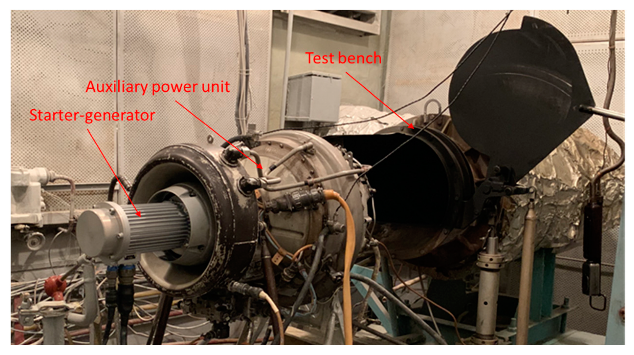
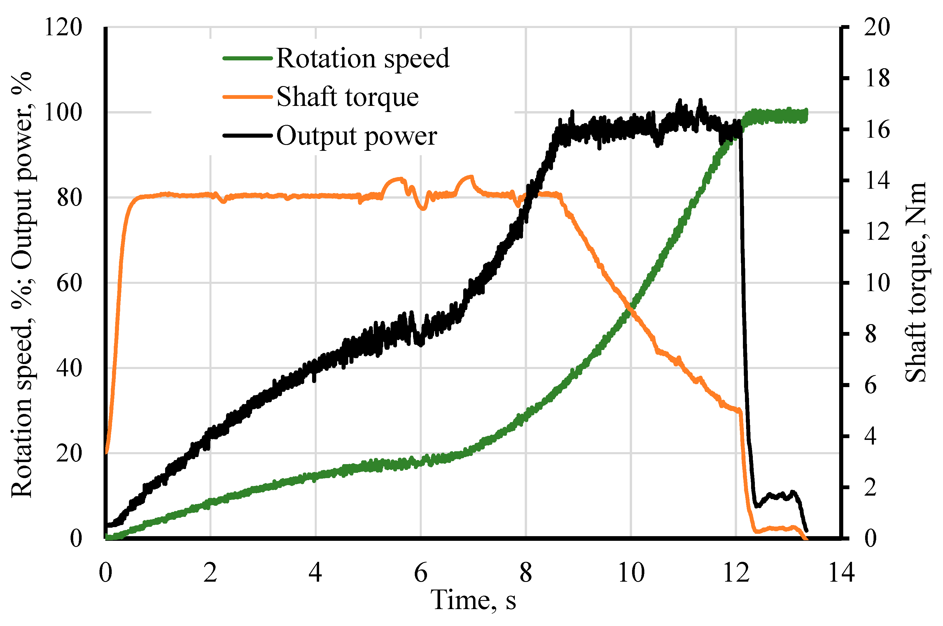
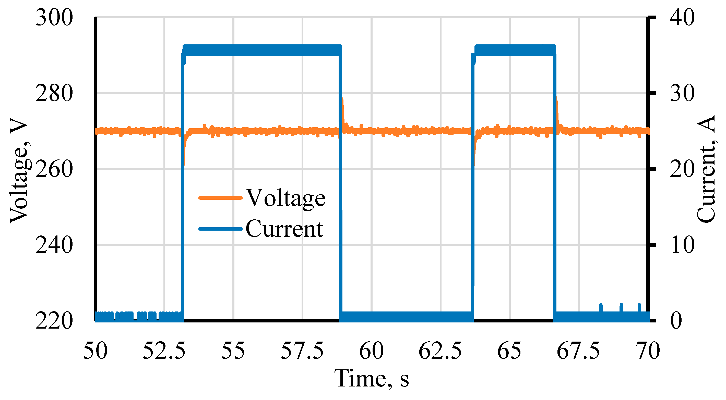
  • The start-up of an aircraft engine from the starter-generator of JSC FED was tested.
  • The engine starting time was 12 s (transition to idle with starter-generator output power up to 16 kW).
  • During operating at generator mode, the stability of the output voltage at 270VDC was confirmed. Deviations from the rating during load on/off switching were less than 10 V, which is within the permissible limits according to the MIL-STD-704 standard.
Based on the investigation carried out, a conclusion was made that application of four phase SR electric machines with the use of independent controllers for each phase is the optimal solution for SG and G located directly on the shafts of the high-pressure compressor and low-pressure turbine.

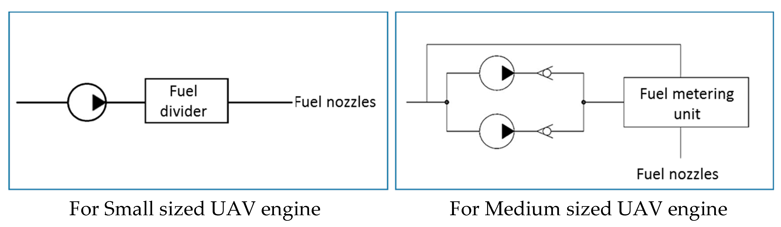
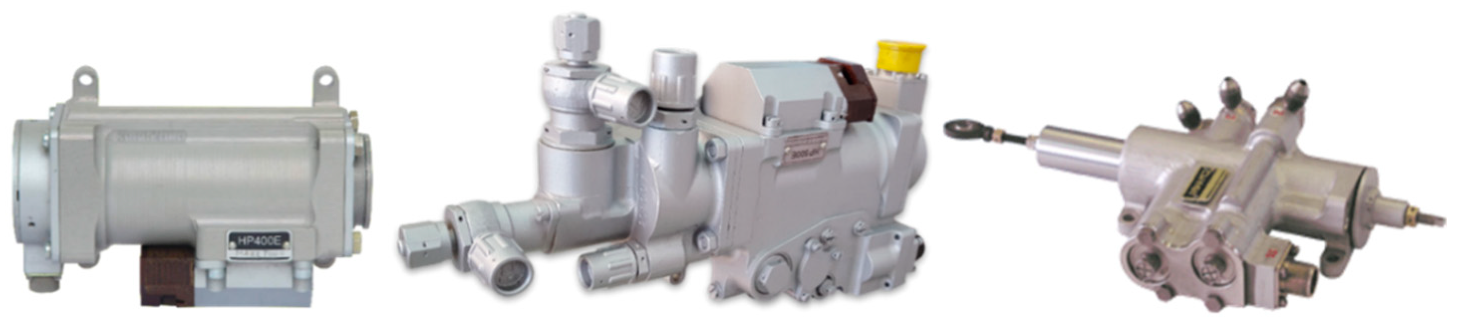
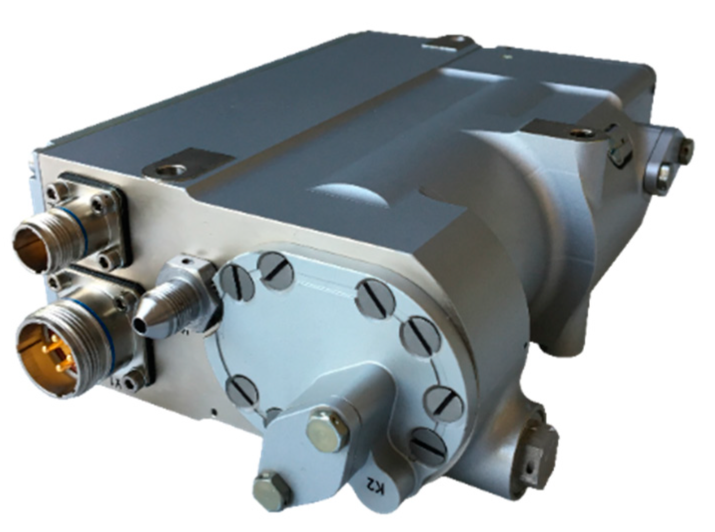
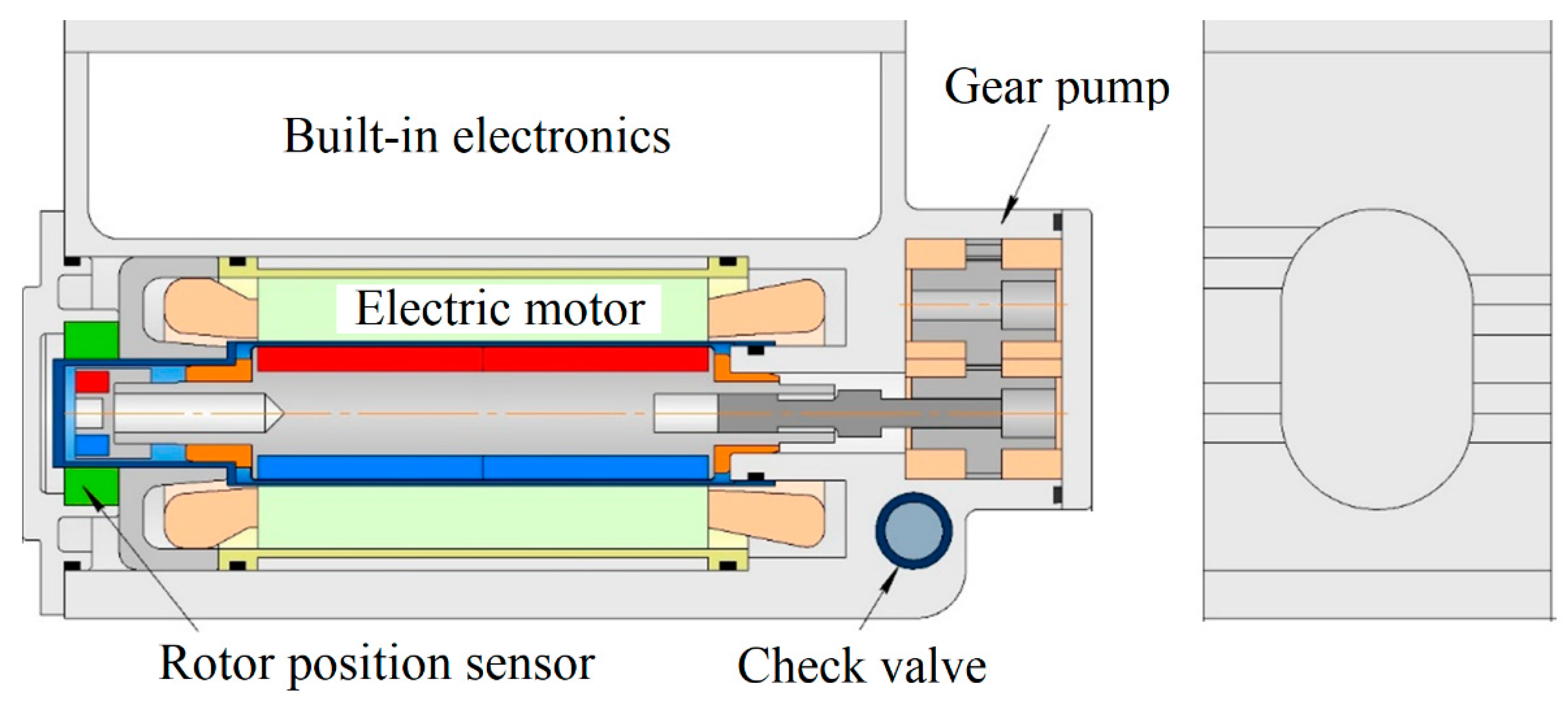
4.2. Electrically Driven Fuel Pump
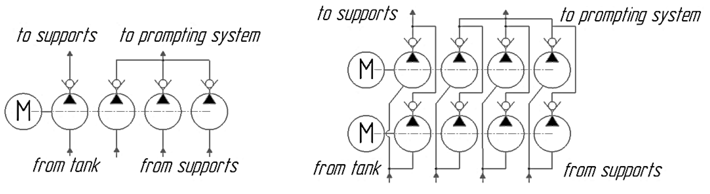
For a fuel metering system of more electric engine, to the use electric drive pumps is proposed. The existing development and serial production experience of the new generation of such units (Figure 12) ensures the compactness and high efficiency of smart metering units, which include an electric motor, a pump and a control system.
The critical review of various types of pumps, fuel metering systems, cooling systems, reliability and redundancy issues were done. Based on the analysis, a configuration with a PMSM electric motor and a gear pump was selected. For the medium-sized UAV, it is proposed to achieve redundancy of fuel pumps by driving each of the pump independently by one motor. In nominal mode, each of the pumps provides 50% of the required flow. At the emergency mode, when one electric drive is broken, the second is switched to an increased mode of operation, ensuring 75% of the required flow rate (Figure 13).
Slide bearings are selected for the pump and electric motor supports. This solution will provide the required service life. The configuration of a synchronous electric motor with permanent magnets on the rotor used by FED for fuel pumps with an integrated power supply and control system was chosen as the basic configuration for the fuel pump electric motor.
The rotor is of a wet type. Magnets were made from neodymium-iron-boron composition. The shape of magnets is specially formed to reduce the step moment and torque pulsation under load. The stator is separated from the fluid flow area by a non-magnetic sleeve.
The calculation of the parameters of the electric motor was carried out by analytical and finite element (plane problem) methods using specialized software, (such as Ansys Electronics). The control system is FOC (Field Oriented Control).
The design of the electric drive pump is shown in Figure 14.

4.3. Oil Pump

The comparative analysis of independent and partially dependent drives of supply and return oil pumps is carried out, the main methods of redundancy are considered, and the reliability and cooling methods analyses are done.
The configuration of the oil system in which every electric drive is working on multi-section supply and return oil pump block is now described. Redundancy for a medium sized UAV engine is carried out due to the parallel operation of two electric drives (Figure 15).
PMSM electric motor with wet rotor and dry stator was chosen as the main configuration.

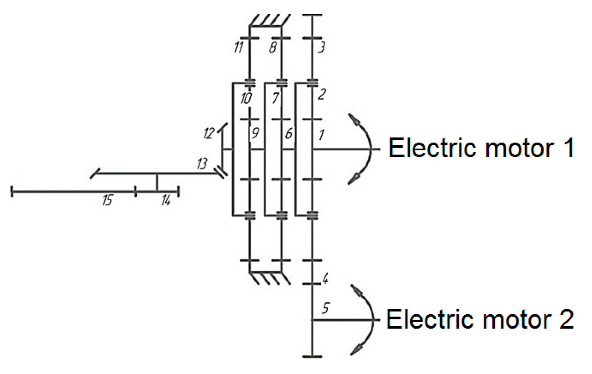
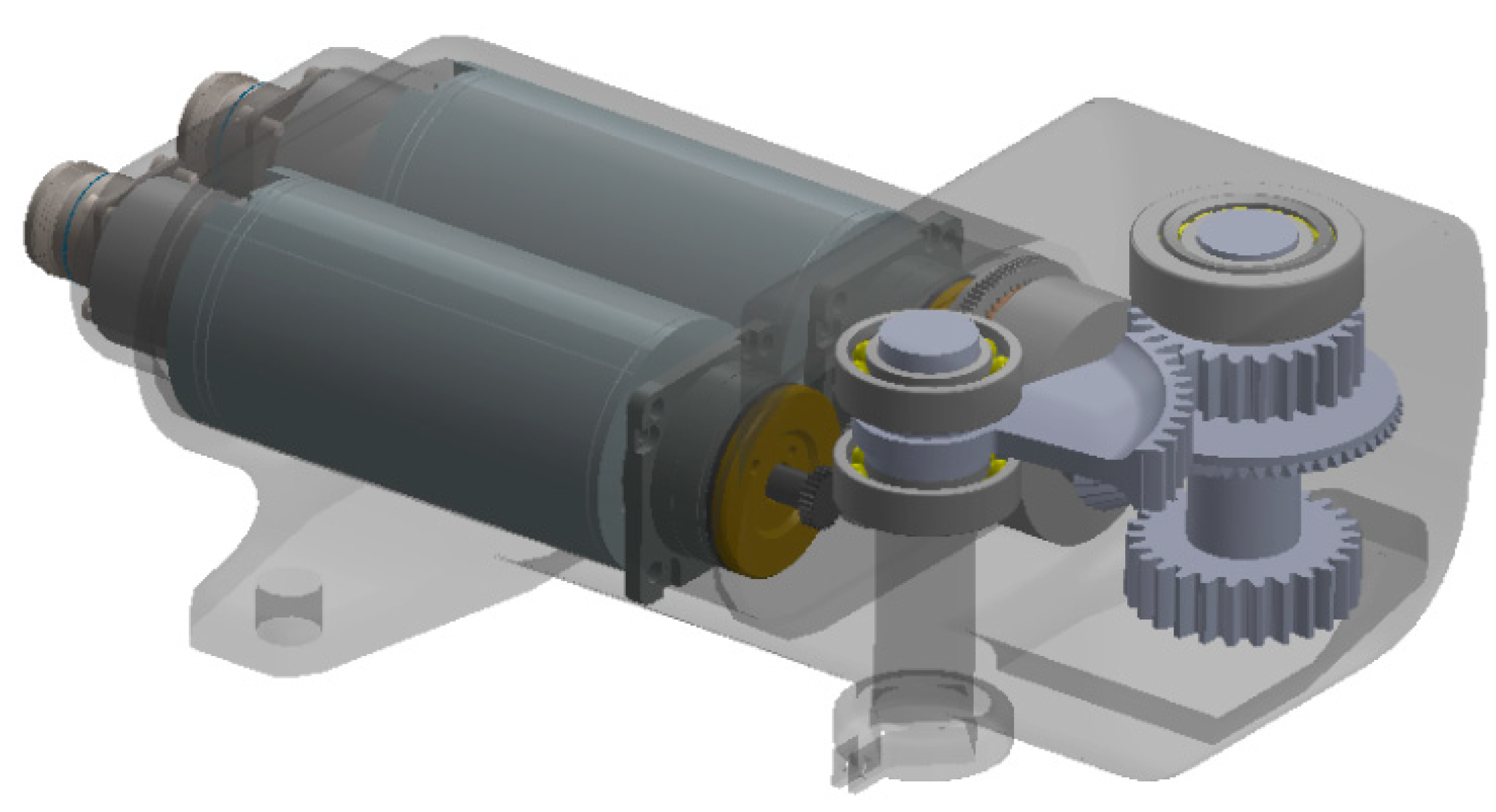
4.4. Guide Vanes Actuator

A comparative analysis was carried out for the electrohydraulic linear (EHSA) and electromechanical rotary (EMA) guide vanes actuators. The analysis showed that the rotary GVA has smaller dimensions and a smaller measuring inaccuracy of the output link rotation angle compared to the linear one. The use of a gearbox in a rotary drive configuration will allow the GVA shaft rotation without the linear motion conversion into a rotary motion, which eliminates additional elements and increases the reliability of the system.
The mechanical part of the actuator consists of a three-stage planetary gearbox, bevel and cylindrical linear gears. The kinematic diagram of the mechanical part of the actuator is shown in Figure 16.
An electromechanical guide vane actuator based on two PMSM electric motors connected by differential gearbox was chosen as the basic variant. In the case of electric motor or control electronic unit failure, the shaft of the corresponding motor is blocked by an electromagnetic brake (Figure 17).
The GVA does not have built-in electronics due to potentially high temperatures at the installation point. The parameters of the gearwheels of the planetary gear and linear gears are selected based on the strength analysis according to ISO 6336 (for spur gears) and ISO 10300 (for bevel gears).

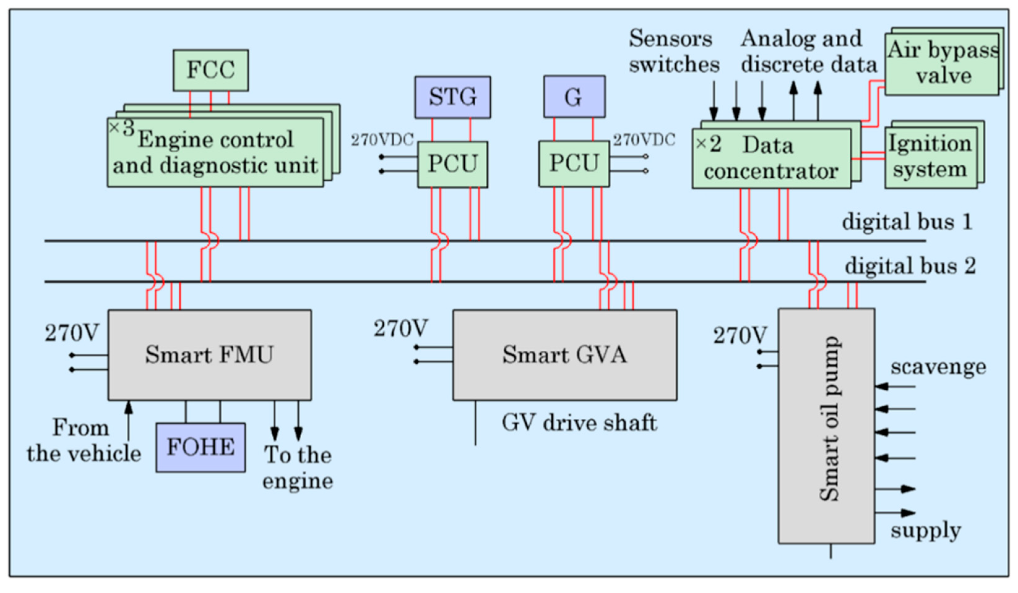
4.5. Engine Control System

Critical analysis was carried out for two versions of the full authority digital engine control system (FADEC): with combined data concentrator and electric engine control and diagnostic unit, and with separate control and diagnostic subsystems. As a result, according to objective criteria (in terms of increasing reliability, maintainability and simplifying software certification for engine management systems), an option with separate subsystems was chosen (Figure 18).
The proposed distributed architecture of a more electric engine units consists of independent and redundant engine control, diagnostic unit, and data concentrator; one or two electric machines, which are located on high-pressure compressor and low-pressure turbine shafts, with an independent power supply and control units, separate smart fuel supply and metering units, a guide vane actuator and oil system units. All of the above-mentioned units are connected to each other via digital transmitted buses.

5. Conclusions

The work that was carried out made it possible to develop the architecture of units and control systems for a more electric motor for small and medium-sized UAVs, as well as to work out the technical aspects of the main subsystems.
The main results of the work are as follows:
  • As SG or G, it is suggested to use SRM electric machines located directly on the shafts of the high-pressure compressor and low-pressure turbine.
  • It is proposed to use independent controllers for each phase to increase the reliability of the system and the ability to control SG and G electrical machines in sensorless mode.
  • It is proposed to use electric-driven integrated pumps as fuel metering units, in which the pump, electric motor and power electronics are located in one case.
  • For the lubrication subsystem, it is proposed to use electrically driven pumps with the placement of several pumps on one shaft. Redundancy is provided by using two independent electrically driven pumps with the ability of transition to a forced operation mode in case of failure of one of them.
  • It is proposed to use a rotary electromechanical guide vanes actuator with a redundant motor and a braking device. This solution ensures the autonomy of the actuator and reduces the overall dimensions.
  • For the engine control system, the FCC redundancy is proposed, with the use of independent digital communication buses and a partially distributed architecture.
The main differences between systems for small and medium-sized UAVs are summarized in Table 2.

Author Contributions

Conceptualization, V.P. and Y.K.; methodology, S.Y.; software, Y.K.; validation, S.Y., Y.K. and A.T.; formal analysis, A.T.; investigation, A.T and Y.K; resources, Y.K.; data curation, S.Y.; writing—original draft preparation, S.Y. and A.T.; writing—review and editing, A.T. and S.Y.; visualization, A.T.; supervision, V.P.; project administration, V.P.; funding acquisition, V.P. All authors have read and agreed to the published version of the manuscript.

Funding

This research received no external funding.

Institutional Review Board Statement

Not applicable.

Informed Consent Statement

Not applicable.

Conflicts of Interest

The authors declare no conflict of interest.

References

  1. Kim, S.J.; Ki, T. Variable guide vane scheduling method based on the kinematic model and dual schedule curves. Appl. Sci. 2020, 10, 6643. [Google Scholar] [CrossRef]
  2. Kai, N.; Yongjiang, L.; Zhanbo, M.; Tianhao, W.; Yihua, H.; Huiqing, W.; Yangang, W. Electrical and electronic technologies in More-Electric Aircraft. A review. IEEE Access 2019, 7, 76145–76166. [Google Scholar]
  3. Morioka, N.; Takeuchi, M.; Oyori, H. Moving to an All-Electric Aircraft System. IHI Eng. Rev. 2014, 47, 33–39. [Google Scholar]
  4. Abdul Sathar Eqbal, M.; Fernando, N.; Marino, M.; Wild, G. Hybrid propulsion systems for remotely piloted aircraft systems. Aerospace 2018, 5, 34. [Google Scholar] [CrossRef] [Green Version]
  5. Frosina, E.; Senatore, A.; Palumbo, L.; Di Lorenzo, G.; Pascarella, C. Development of a lumped parameter model for an aeronautic hybrid electric propulsion system. Aerospace 2018, 5, 105. [Google Scholar] [CrossRef] [Green Version]
  6. Lambert, P.; Alejo, D.; Fefermann, Y.; Maury, C.; Thoraval, B.; Salanne, J.; Isikveren, A. Long-term hybrid-electric propulsion architecture options for transport aircraft. In Proceedings of the Greener Aviation 2016, Brussels, Belgium, 11–13 October 2016. [Google Scholar]
  7. Huang, L.; Yu, T.; Jiao, Z.; Li, Y. Active load-sensitive electro-hydrostatic actuator for more electric aircraft. Appl. Sci. 2020, 10, 6978. [Google Scholar] [CrossRef]
  8. Maré, J.-C. Practical considerations in the modelling and simulation of electromechanical actuators. Actuators 2020, 9, 94. [Google Scholar] [CrossRef]
  9. Sarlioglu, B.; Morris, C. More electric aircraft—Review, challenges and opportunities for commercial transport aircraft. IEEE Trans. Transp. Electrif. 2015, 1, 56–64. [Google Scholar] [CrossRef]
  10. Wheeler, P.; Clare, J.; Trentin, A.; Bozhko, S. An overview of the more electrical aircraft. J. Aerospace Eng. 2012, 227, 578–585. [Google Scholar] [CrossRef]
  11. Bennett, J. Fault Tolerant Electromechanical Actuators for Aircraft. Ph.D. Thesis, Newcastle University, Newcastle upon Tyne, UK, 2010. [Google Scholar]
  12. Abba, F.; Rachek, M. Time-stepping FEM-based multi-level coupling of magnetic field–electric circuit and mechanical structural deformation models dedicated to the analysis of electromagnetic actuators. Actuators 2019, 8, 22. [Google Scholar] [CrossRef] [Green Version]
  13. Madonna, V.; Giangrande, P.; Galea, M. Electrical power generation in aircraft: Review, challenges and opportunities. IEEE Trans. Transp. Electrif. 2018, 4, 646–659. [Google Scholar] [CrossRef]
  14. Nøland, J.; Leandro, M.; Suul, J.; Molinas, M. High-power machines and starter-generator topologies for more electric aircraft: A technology outlook. IEEE Access 2020, 8, 130104–130123. [Google Scholar] [CrossRef]
  15. MacMinn, S.; Jones, W. A very high speed switched-reluctance starter-generator for aircraft engine applications. In Proceedings of the IEEE National Aerospace and Electronics Conference, Dayton, OH, USA, 22–26 May 1989. [Google Scholar]
  16. Geest, M.; Polinder, H.; Ferreira, J.; Zeilstra, D. Design and testing of a high-speed aerospace permanent magnet starter/generator. In Proceedings of the 2015 International Conference on Electrical Systems for Aircraft, Railway, Ship Propulsion and Road Vehicles (ESARS), Aachen, Germany, 3–5 March 2015. [Google Scholar]
  17. Vepa, R. Modeling and dynamics of HTS motors for aircraft electric propulsion. Aerospace 2018, 5, 21. [Google Scholar] [CrossRef] [Green Version]
  18. Shoujuna, S.; Weiguo, L.; Peitsch, L.; Schaeferb, U. Detailed design of a high speed switched reluctance starter/generator for more/all electric aircraft. Chin. J. Aeronaut. 2010, 23, 216–226. [Google Scholar] [CrossRef] [Green Version]
  19. Jafari, S.; Miran Fashandi, S.A.; Nikolaidis, T. Modeling and control of the starter motor and start-up phase for gas turbines. Electronics 2019, 8, 363. [Google Scholar] [CrossRef] [Green Version]
  20. Khowja, M.R.; Vakil, G.; Gerada, C.; Patel, C.; Odhano, S.; Wheeler, P. Integrated motor drive: Mass and volume optimization of the motor with an integrated filter inductor. Energies 2021, 14, 4564. [Google Scholar] [CrossRef]
  21. Nicola, C.-I.; Nicola, M.; Selișteanu, D. Sensorless control of PMSM based on backstepping-PSO-type controller and ESO-type observer using real-time hardware. Electronics 2021, 10, 2080. [Google Scholar] [CrossRef]
  22. Dong, Z.; Liu, C.; Liu, S.; Song, Z. Deadbeat predictive current control for series-winding PMSM drive with half-bridge power module-based inverter. Energies 2021, 14, 4620. [Google Scholar] [CrossRef]
  23. Belkhier, Y.; Achour, A.; Shaw, R.N.; Ullah, N.; Chowdhury, M.S.; Techato, K. Fuzzy supervisory passivity-based high order-sliding mode control approach for tidal turbine-based permanent magnet synchronous generator conversion system. Actuators 2021, 10, 92. [Google Scholar] [CrossRef]
  24. Lakhe, R.K.; Chaoui, H.; Alzayed, M.; Liu, S. Universal control of permanent magnet synchronous motors with uncertain dynamics. Actuators 2021, 10, 49. [Google Scholar] [CrossRef]
Figure 1. JSC ‘FED’ electrically driven fuel pumps without (left) and with (middle) integrated booster stage and fuel divider; Guide vanes actuator (right).
Aerospace 08 00316 g001
Figure 2. Medium size UAV engine concept.
Aerospace 08 00316 g002
Figure 3. Small size UAV engine concept.
Aerospace 08 00316 g003
Figure 4. PMSM Power Control Unit diagram.
Aerospace 08 00316 g004
Figure 5. SRM Power Control Unit diagram.
Aerospace 08 00316 g005
Figure 6. SRM electrical machine control board (power components aren’t shown).
Aerospace 08 00316 g006
Figure 7. Prototype of SRM electric machine.
Aerospace 08 00316 g007
Figure 8. SG9 demonstrator and SGCU9 power supply and control unit.
Aerospace 08 00316 g008
Figure 9. Dependence of the speed, power consumption and SG shaft torque on time during engine start.
Aerospace 08 00316 g009
Figure 10. Transient processes during load on/off switching at the generator mode operating.
Aerospace 08 00316 g010
Figure 11. Starter-generator on the APU.
Aerospace 08 00316 g011
Figure 12. JSC FED Electrically driven fuel metering unit (PMSM electric motor + gear pump) with built-in control electronic (serial production).
Aerospace 08 00316 g012
Figure 13. Fuel metering line diagram.
Aerospace 08 00316 g013
Figure 14. Design of the electric drive pump.
Aerospace 08 00316 g014
Figure 15. Connection diagram of oil pumps with electric drives.
Aerospace 08 00316 g015
Figure 16. Kinematic diagram of the mechanical part of the actuator.
Aerospace 08 00316 g016
Figure 17. General view of the electromechanical GVA.
Aerospace 08 00316 g017
Figure 18. Proposed distributed architecture scheme of a more electric engine for middle-sized UAV (for small-sized UAV the scheme is equal except one digital bus). FOHE—fuel oil heat exchanger; FMU—fuel metering unit; GVA—guide vanes actuator; FCC—flight control controller; SG—starter-generator; G—generator; PCU—power control unit.
Aerospace 08 00316 g018
Table 1. SG and G parameters for small and medium size UAV.
ParameterMedium-Size UAVSmall-Size UAV
SGGSG
1Rotor speed range, rpmup to 40,000up to 15,000up to 45,000
2Max output power in starter mode, kW40-20
3Max output power in generator mode, kW253014
Table 2. Proposed features of a distributed system for more electric engines of small and middle sized UAVs.
SubsystemSmall Sized UAVMedium Sized UAV
1Engine start and power generationFour phases SRM SGFour phases SRM SG and G
2Fuel meteringElectrically driven fuel pumpRedundant system with two electrically driven fuel pumps and fuel metering unit
3Oil pumpElectrically driven oil pump unitRedundant system with two oil pump units and integrated electric motors
4Guide vanes actuatorNot requiredElectromechanical with redundant two independent electrical motors
5Engine control systemOne channel FCC with single digital busTriple redundant FCC with two independent digital buses
Publisher’s Note: MDPI stays neutral with regard to jurisdictional claims in published maps and institutional affiliations.

