Aerostructural Design Exploration of a Wing in Transonic Flow †


Abstract
1. Introduction
1.1. Background
This should be one of the aims for the future: we want an integrated aerodynamic and structural analysis of the dynamics of the flying vehicle as one deformable body, and to use that for design purposes.
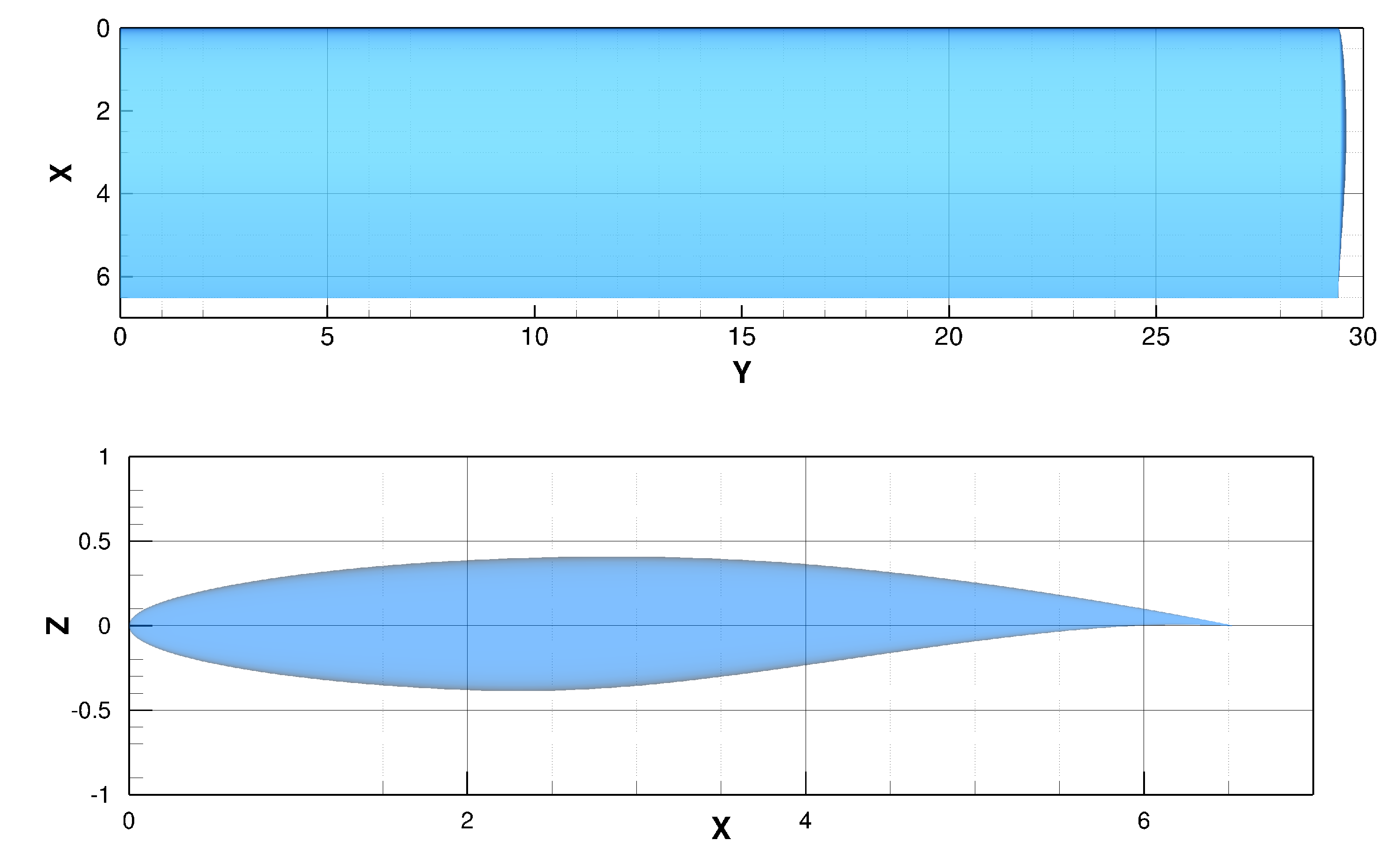
1.2. Problem Description
2. Methods and Tools
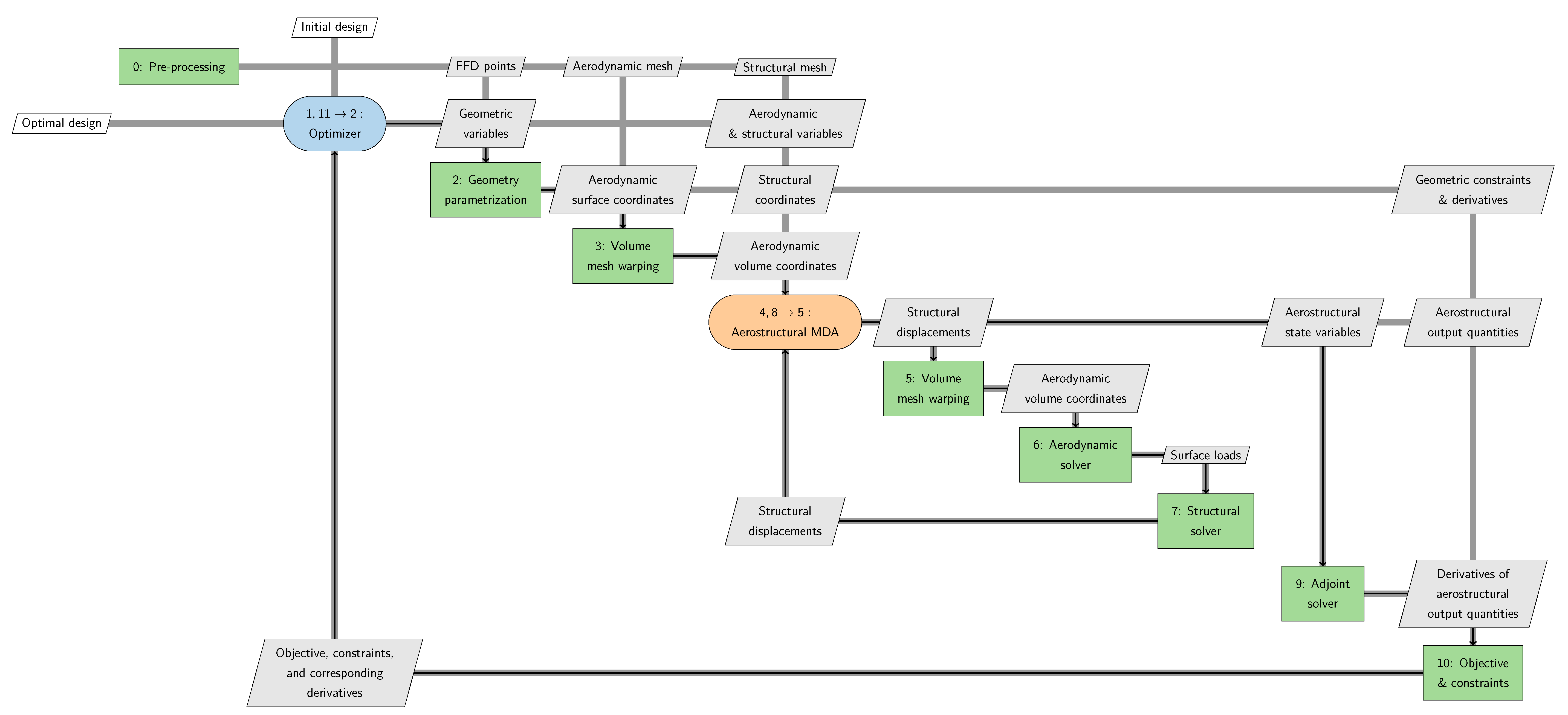
2.1. Computational Framework
2.2. Preprocessing
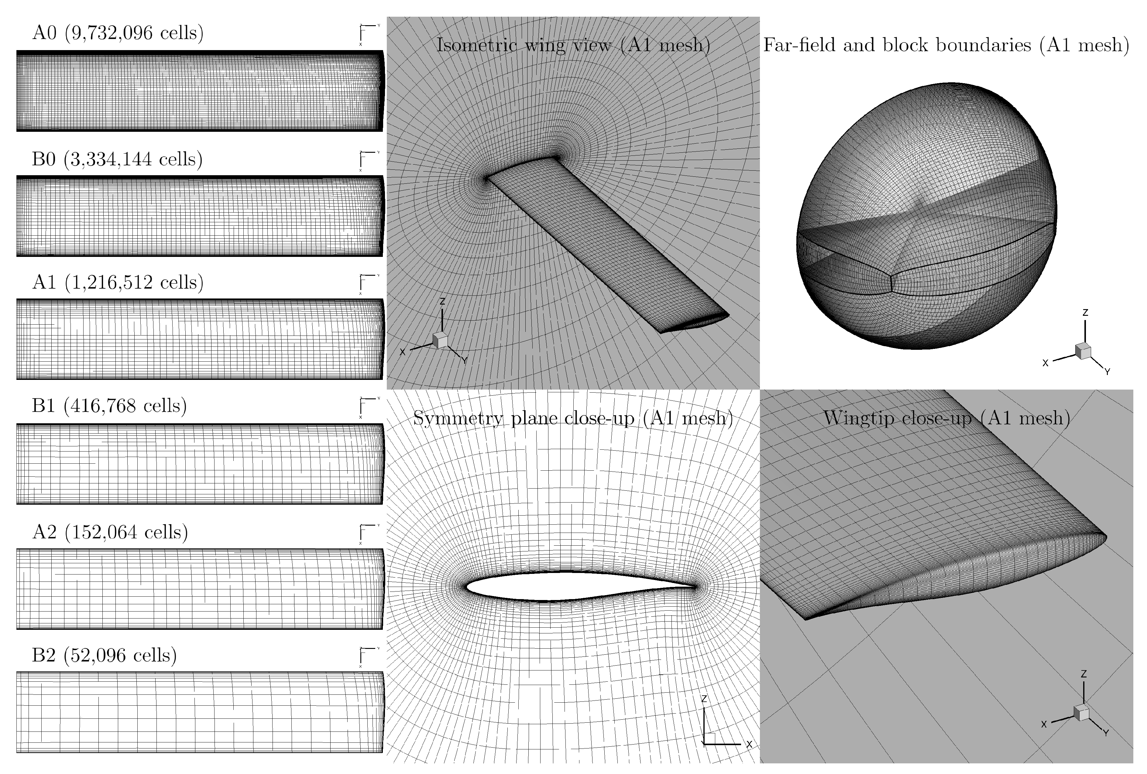
2.2.1. CFD Meshing
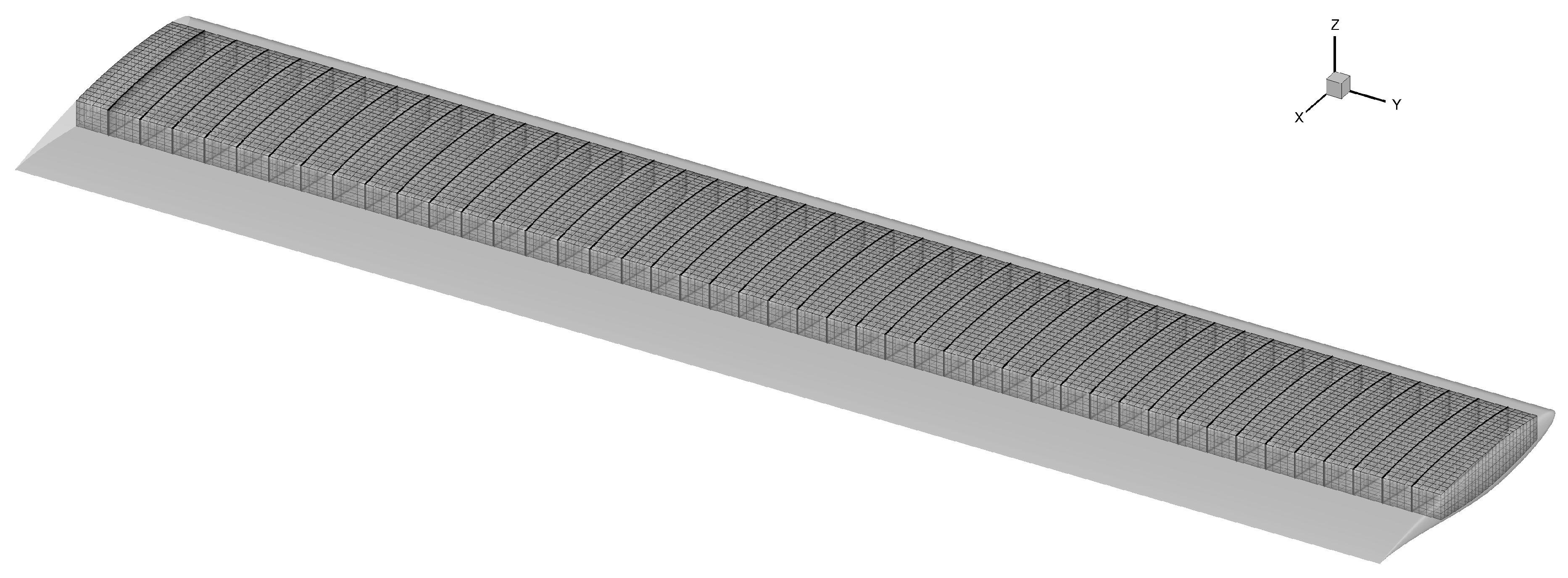
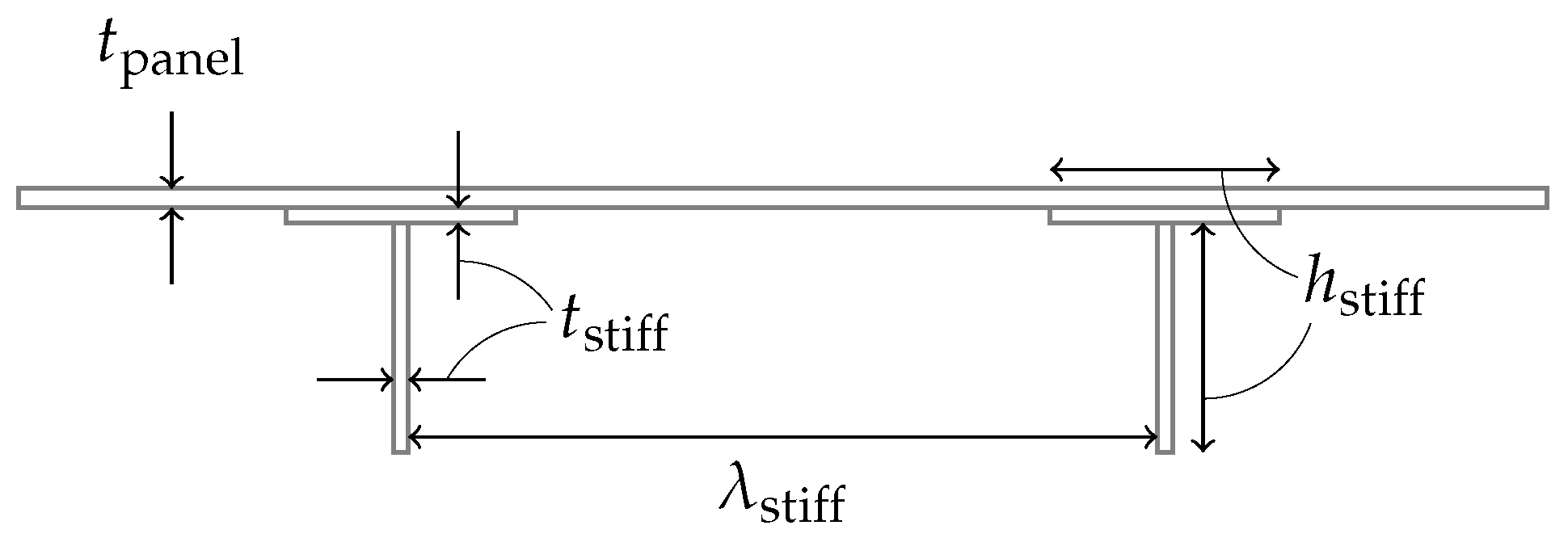
2.2.2. FEA Meshing
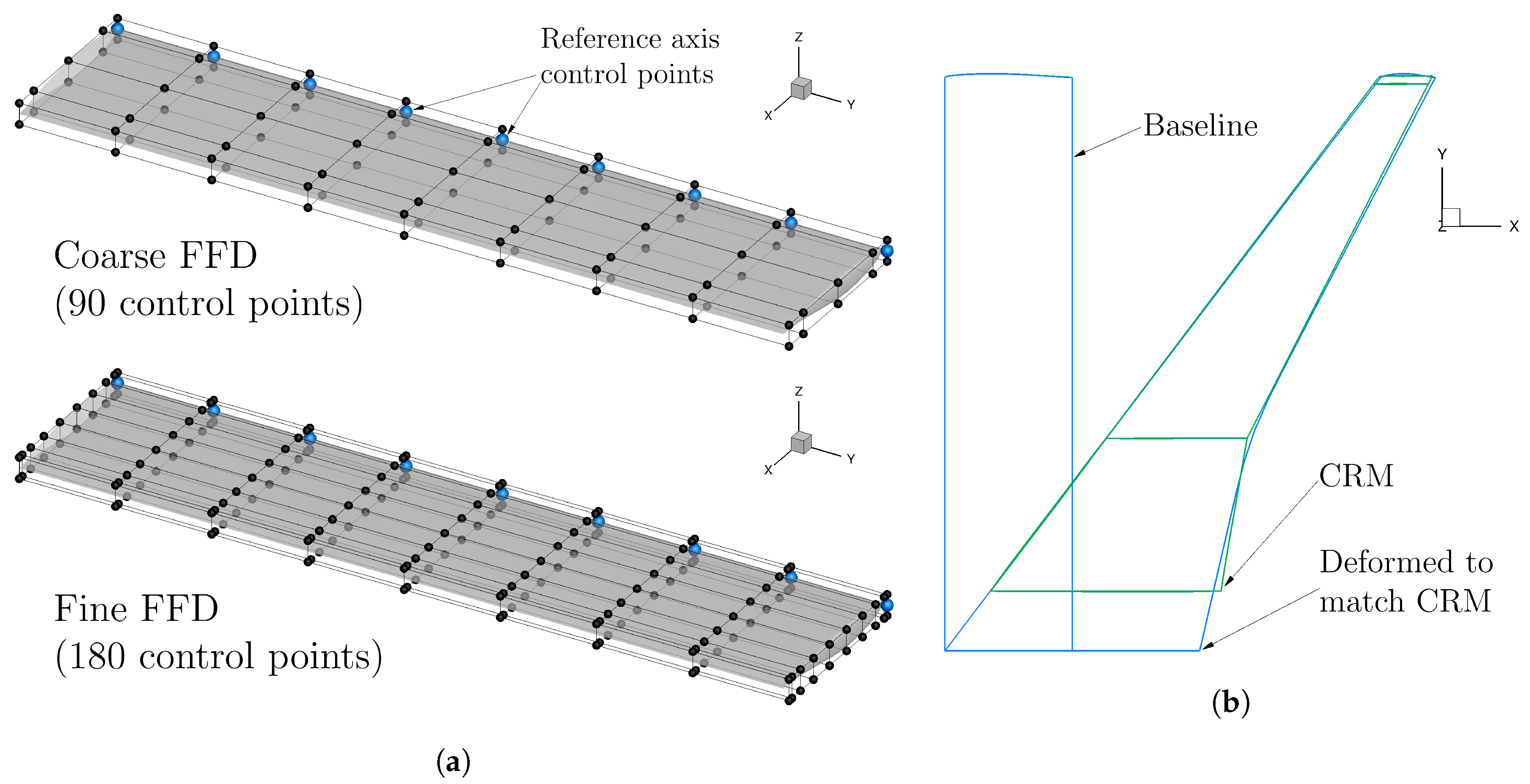
2.2.3. Geometric Parametrization
2.3. Optimization Problem
2.3.1. Objective Function
2.3.2. Design Variables
2.3.3. Design Constraints
2.4. Structural Pre-Optimization
2.5. Multipoint Optimization Problem
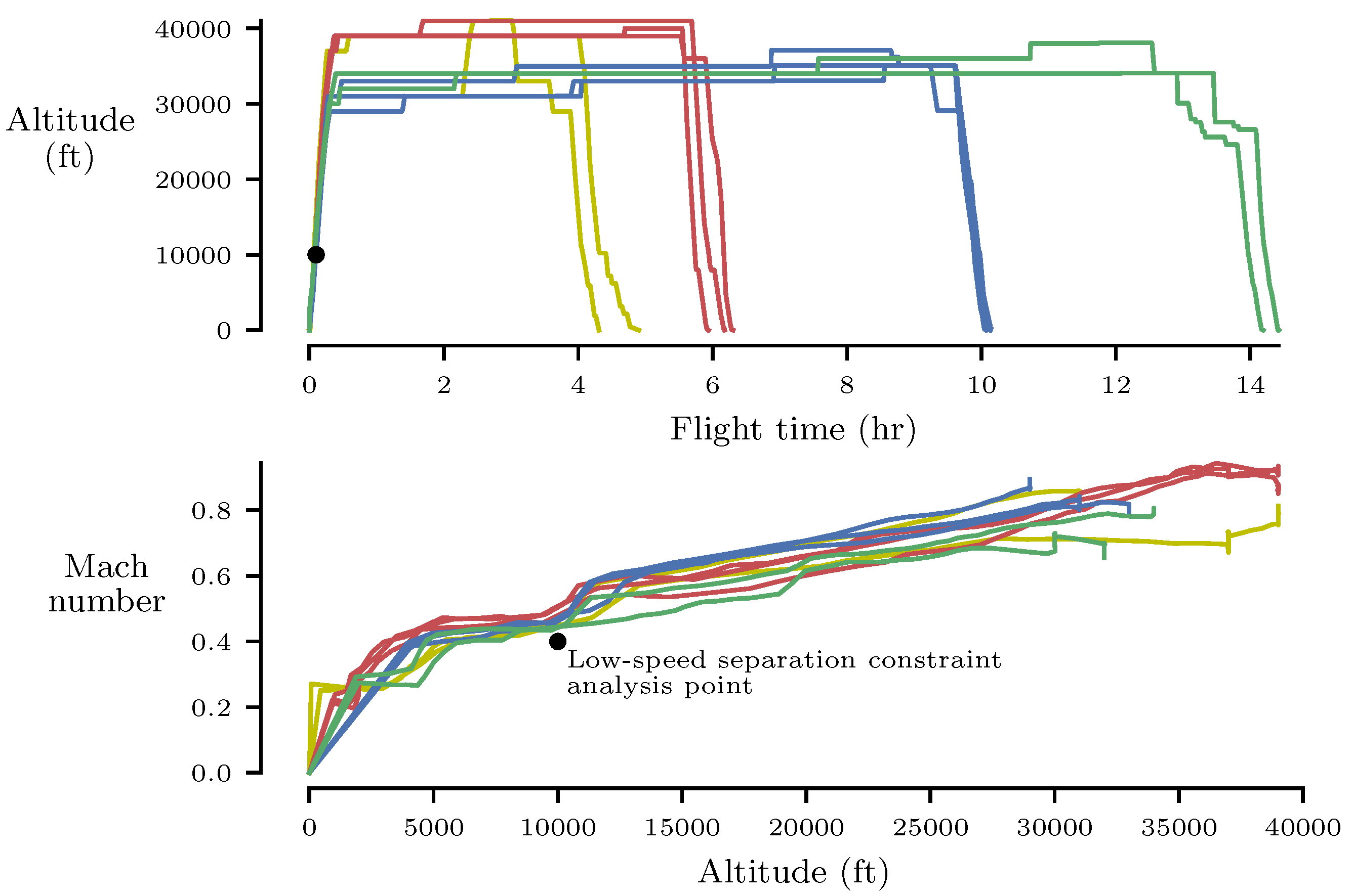
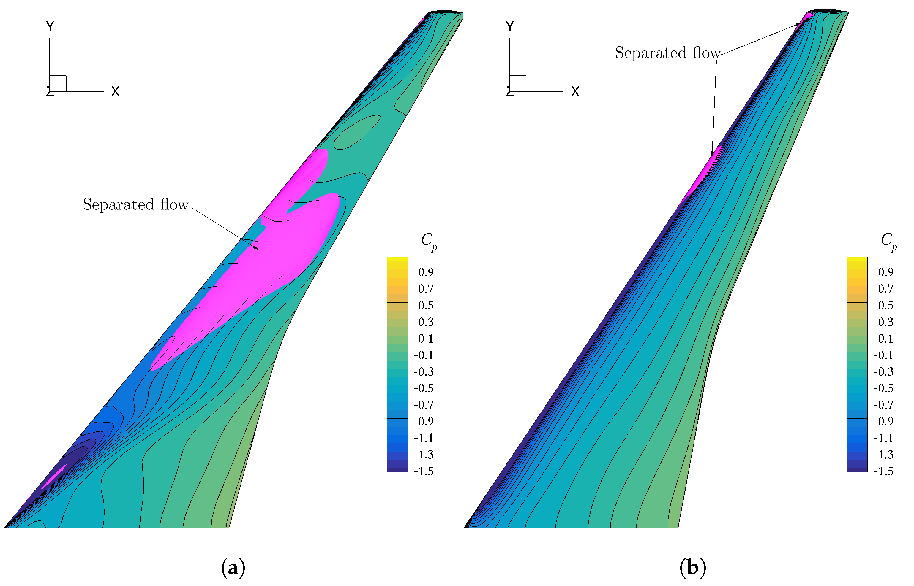
2.6. Low-Speed, High-Lift Separation Constraint
3. Results
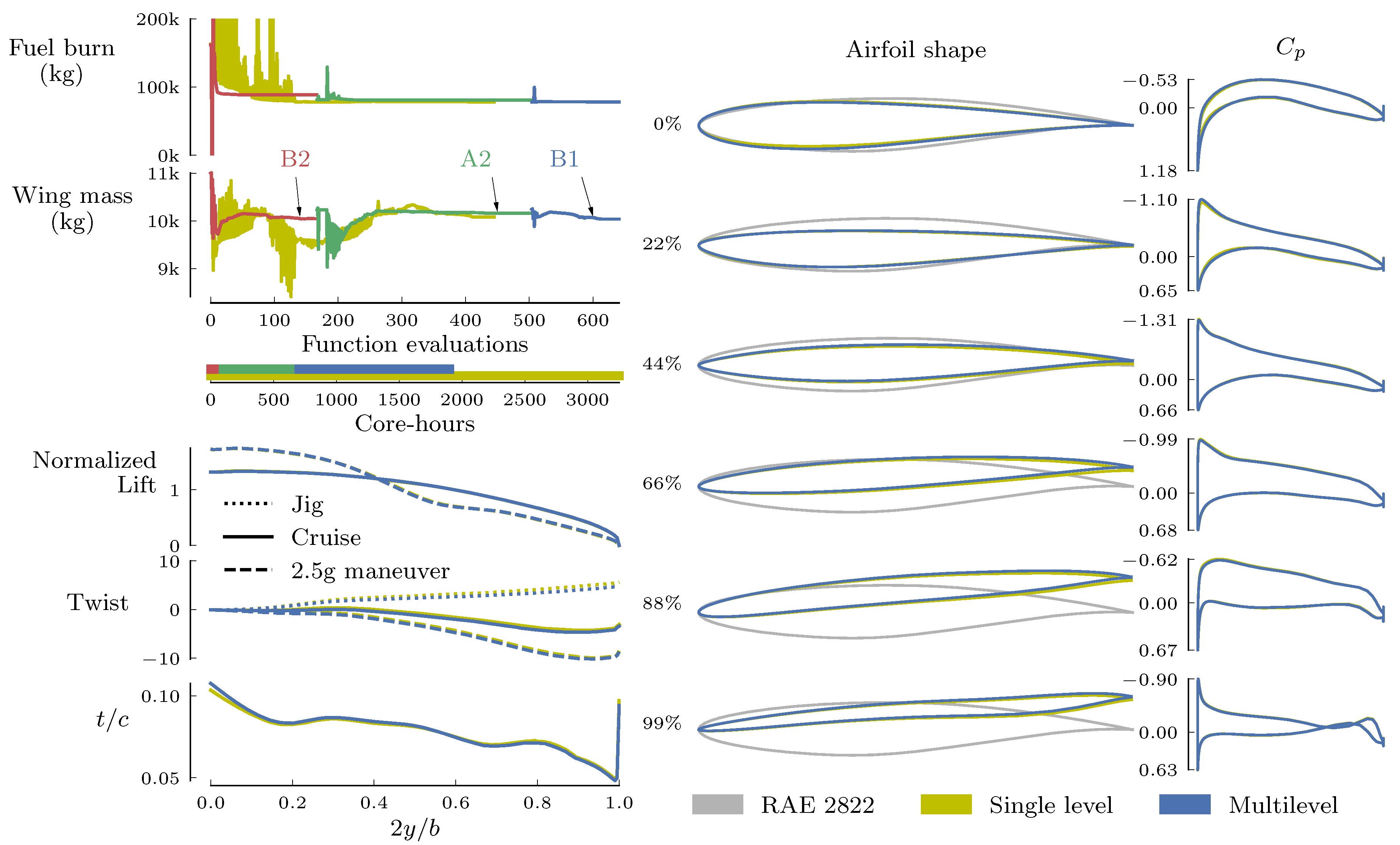
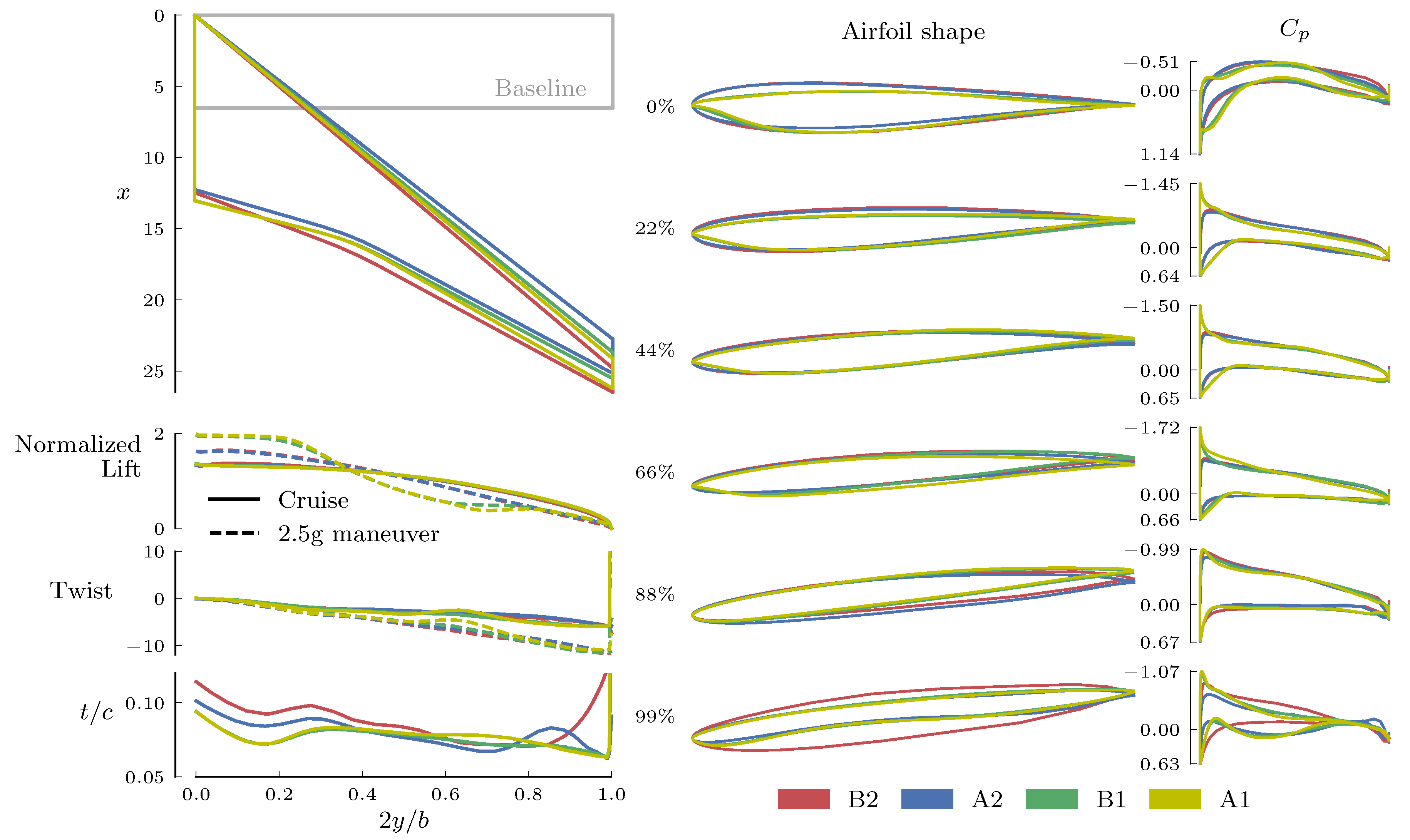
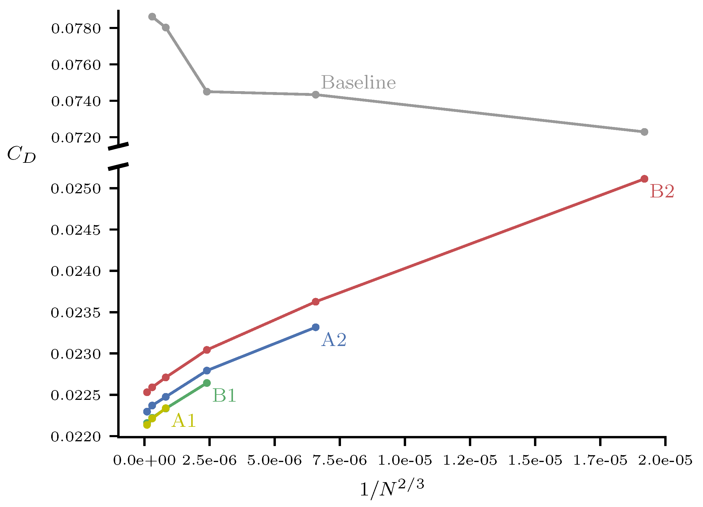
3.1. Multi-Level Optimization Procedure
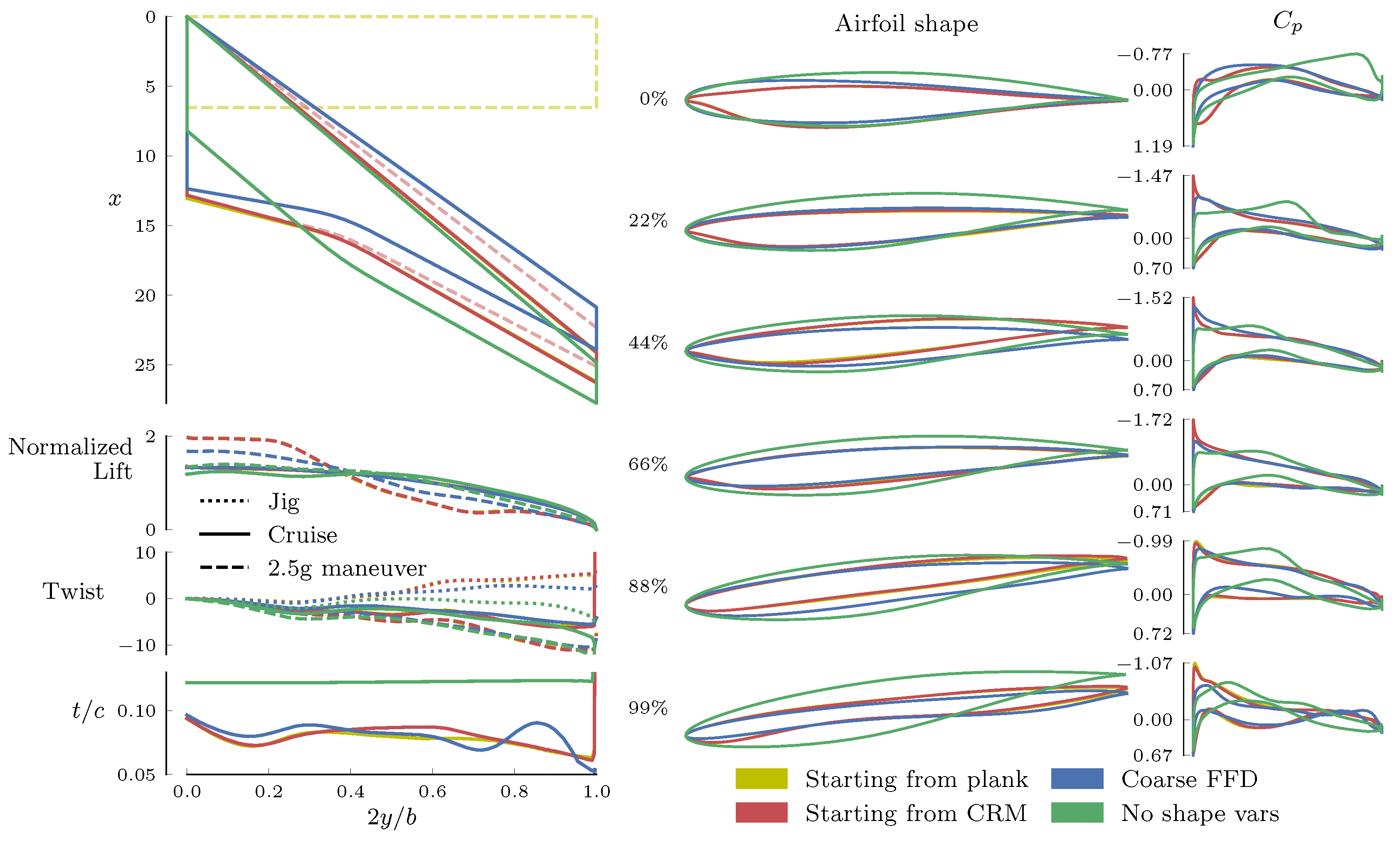
3.2. Single-Point Optimization
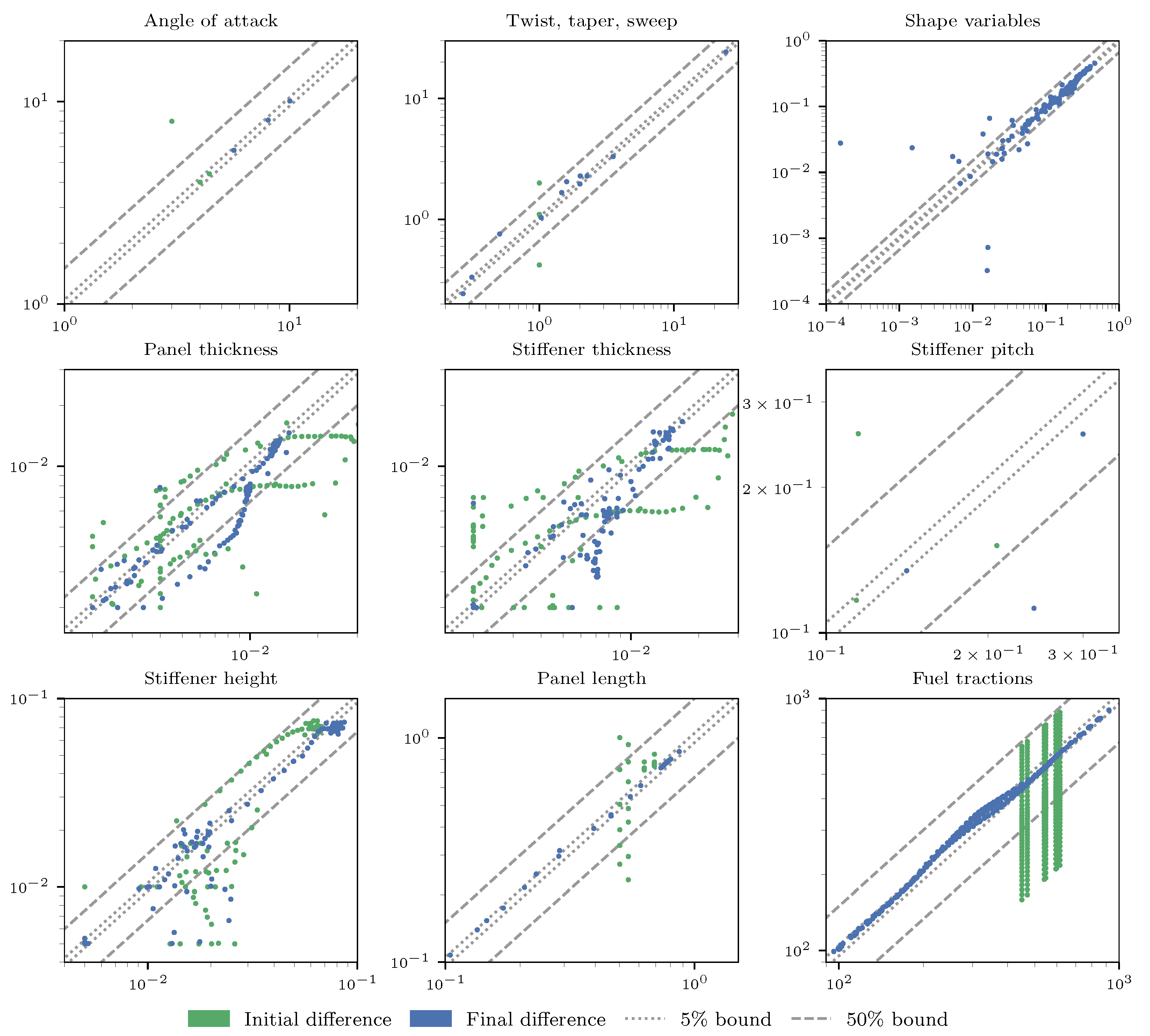
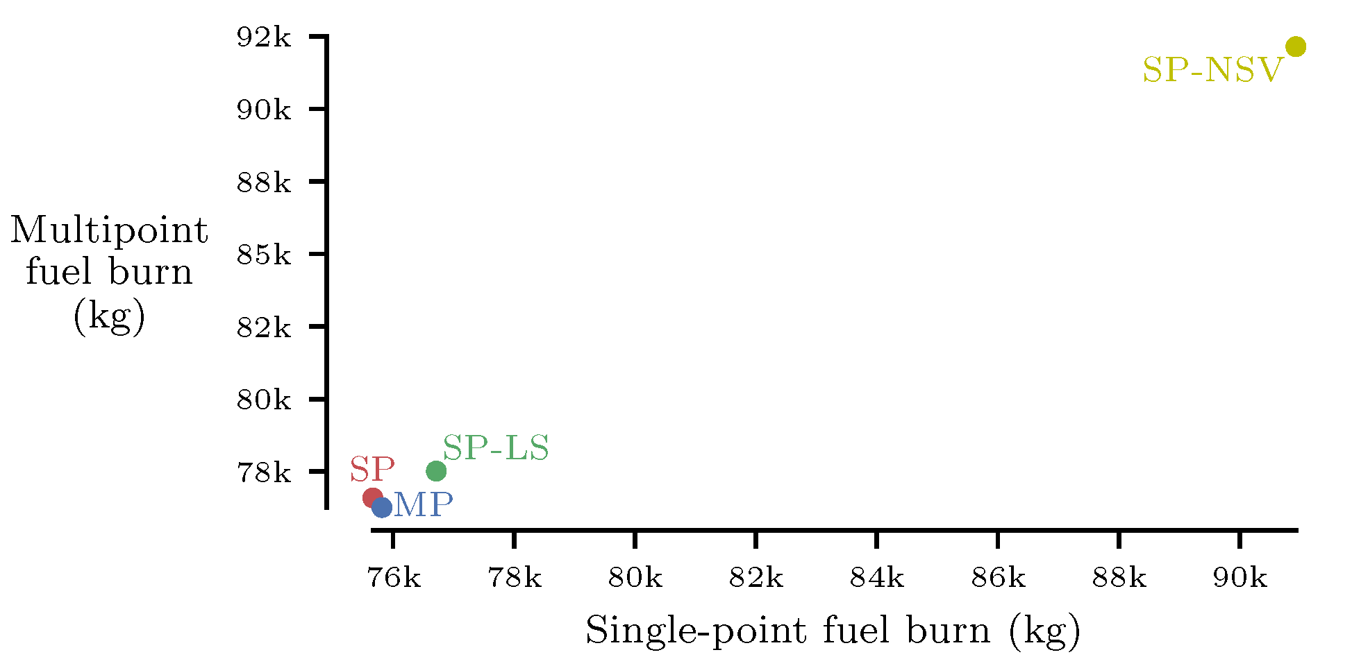
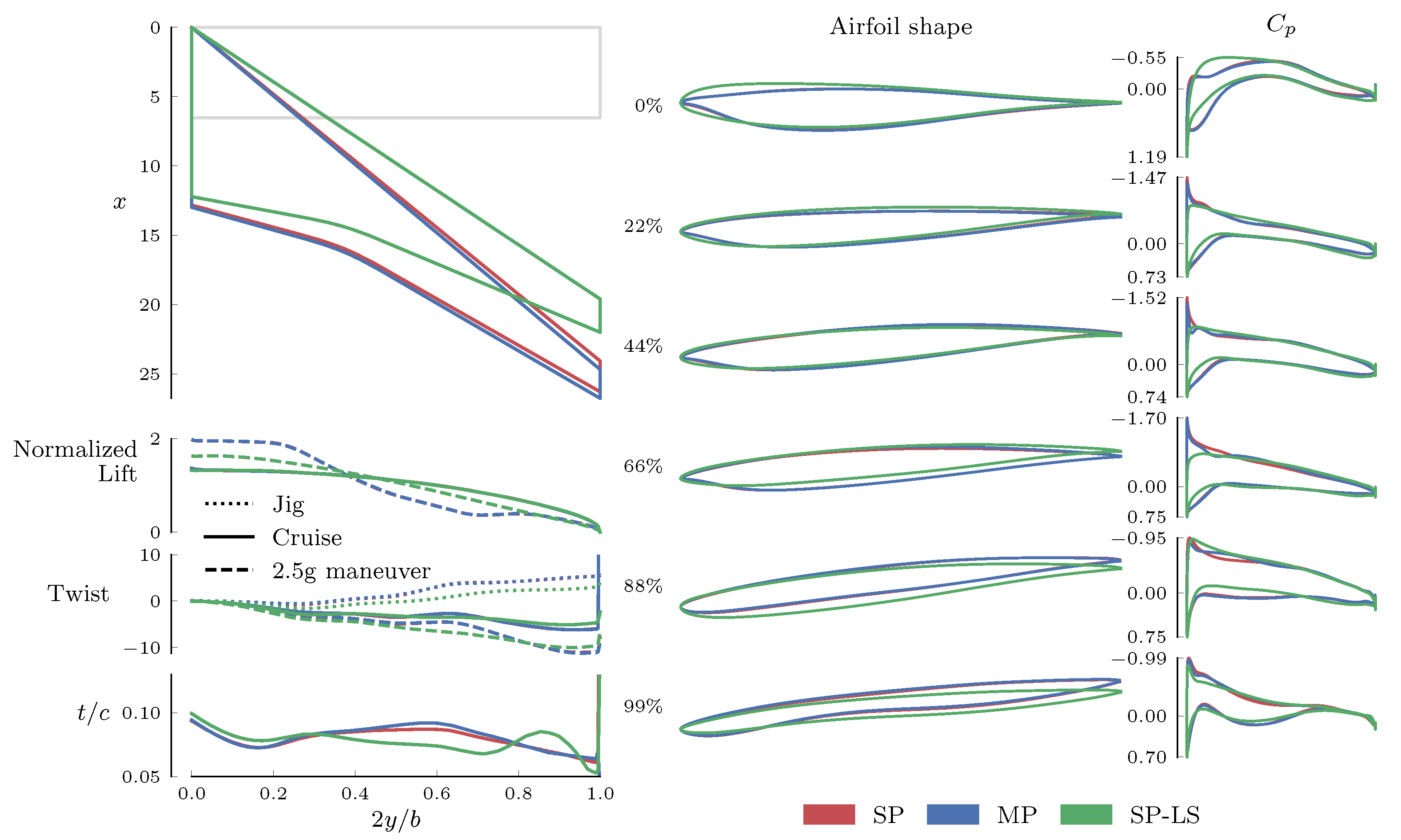
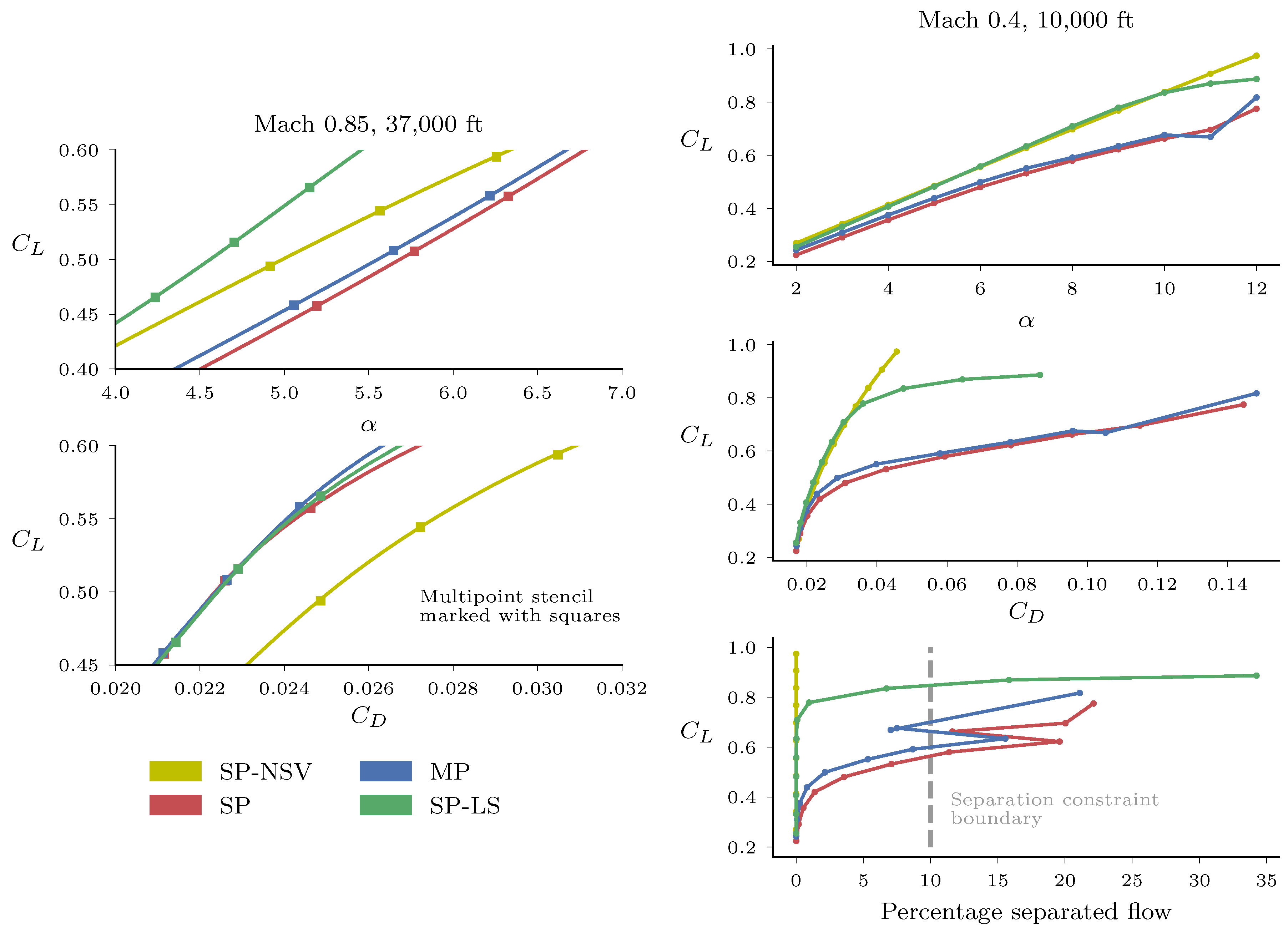
3.3. Robust Design Optimization
- (SP) The single-point design from Section 3.2 (started from the CRM planform).
- (MP) A three-point design with , , and at Mach 0.85 and 37,000 ft.
- (SP-LS) A single-point design with a separation constraint at Mach 0.4 and 10,000 ft.
- (SP-NSV) Result of single-point optimization without shape variables (RAE 2822 cross-sections).
4. Discussion
5. Conclusions
Author Contributions
Funding
Acknowledgments
Conflicts of Interest
Abbreviations
| AD | automatic differentiation |
| ADODG | Aerodynamic Design Optimization Discussion Group |
| AIAA | American Institute of Aeronautics and Astronautics |
| ASO | aerodynamic shape optimization |
| CFD | computational fluid dynamics |
| CRM | Common Research Model |
| DNS | direct numerical simulation |
| DPW | Drag Prediction Workshop |
| FEA | finite element analysis |
| FFD | free-form deformation |
| KKT | Karush–Kuhn–Tucker |
| KS | Kreisselmeier–Steinhauser |
| LES | large eddy simulation |
| MAC | mean aerodynamic chord |
| MACH | MDO of aircraft configurations with high fidelity |
| MDAO | multidisciplinary analysis and optimization |
| MDO | multidisciplinary design optimization |
| MITC | mixed interpolation of tensorial components |
| OML | outer mold line |
| RAE | Royal Aircraft Establishment |
| RANS | Reynolds-averaged Navier–Stokes |
| TACS | Toolkit for the Analysis of Composite Structures |
| uCRM | undeflected Common Research Model |
| XDSM | extended design structure matrix |
References
- Kuchemann, D. The Aerodynamic Design of Aircraft: A Detailed Introduction to the Current Aerodynamic Knowledge and Practical Guide to the Solution of Aircraft Design Problems; Pergamon Press: Oxford, UK, 1978. [Google Scholar]
- Haftka, R.T. Optimization of Flexible Wing Structures Subject to Strength and Induced Drag Constraints. AIAA J. 1977, 15, 1101–1106. [Google Scholar] [CrossRef]
- Chittick, I.R.; Martins, J.R.R.A. Aero-Structural Optimization Using Adjoint Coupled Post-Optimality Sensitivities. Struct. Multidiscip. Optim. 2008, 36, 59–70. [Google Scholar] [CrossRef]
- Jansen, P.; Perez, R.E.; Martins, J.R.R.A. Aerostructural Optimization of Nonplanar Lifting Surfaces. J. Aircr. 2010, 47, 1491–1503. [Google Scholar] [CrossRef]
- Jasa, J.P.; Hwang, J.T.; Martins, J.R.R.A. Open-source coupled aerostructural optimization using Python. Struct. Multidiscip. Optim. 2018, 57, 1815–1827. [Google Scholar] [CrossRef]
- Gray, J.S.; Hwang, J.T.; Martins, J.R.R.A.; Moore, K.T.; Naylor, B.A. OpenMDAO: An open-source framework for multidisciplinary design, analysis, and optimization. Struct. Multidiscip. Optim. 2019, 59, 1075–1104. [Google Scholar] [CrossRef]
- Yu, Y.; Lyu, Z.; Xu, Z.; Martins, J.R.R.A. On the Influence of Optimization Algorithm and Starting Design on Wing Aerodynamic Shape Optimization. Aerosp. Sci. Technol. 2018, 75, 183–199. [Google Scholar] [CrossRef]
- Martins, J.R.R.A.; Hwang, J.T. Review and Unification of Methods for Computing Derivatives of Multidisciplinary Computational Models. AIAA J. 2013, 51, 2582–2599. [Google Scholar] [CrossRef]
- Martins, J.R.R.A.; Sturdza, P.; Alonso, J.J. The Complex-Step Derivative Approximation. ACM Trans. Math. Softw. 2003, 29, 245–262. [Google Scholar] [CrossRef]
- Jameson, A. Aerodynamic Design via Control Theory. J. Sci. Comput. 1988, 3, 233–260. [Google Scholar] [CrossRef]
- Kenway, G.K.W.; Mader, C.A.; He, P.; Martins, J.R.R.A. Effective Adjoint Approaches for Computational Fluid Dynamics. Prog. Aerosp. Sci. 2019, 110, 100542. [Google Scholar] [CrossRef]
- Martins, J.R.R.A.; Alonso, J.J.; Reuther, J.J. A Coupled-Adjoint Sensitivity Analysis Method for High-Fidelity Aero-Structural Design. Optim. Eng. 2005, 6, 33–62. [Google Scholar] [CrossRef]
- Martins, J.R.R.A.; Alonso, J.J.; Reuther, J.J. High-Fidelity Aerostructural Design Optimization of a Supersonic Business Jet. J. Aircr. 2004, 41, 523–530. [Google Scholar] [CrossRef]
- Khosravi, S.; Zingg, D.W. Aerostructural Perspective on Winglets. J. Aircr. 2017, 54. [Google Scholar] [CrossRef]
- Khosravi, S.; Zingg, D.W. Aerostructural Optimization of Drooped Wings. J. Aircr. 2018, 55, 1261–1268. [Google Scholar] [CrossRef]
- Kenway, G.K.W.; Kennedy, G.J.; Martins, J.R.R.A. Scalable Parallel Approach for High-Fidelity Steady-State Aeroelastic Analysis and Derivative Computations. AIAA J. 2014, 52, 935–951. [Google Scholar] [CrossRef]
- Burdette, D.A.; Martins, J.R.R.A. Impact of Morphing Trailing Edge on Mission Performance for the Common Research Model. J. Aircr. 2019, 56, 369–384. [Google Scholar] [CrossRef]
- Brooks, T.R.; Kenway, G.K.W.; Martins, J.R.R.A. Benchmark Aerostructural Models for the Study of Transonic Aircraft Wings. AIAA J. 2018, 56, 2840–2855. [Google Scholar] [CrossRef]
- Brooks, T.R.; Martins, J.R.R.A.; Kennedy, G.J. Aerostructural Trade-offs for Tow-steered Composite Wings. J. Aircr. 2020. [Google Scholar] [CrossRef]
- Brooks, T.R.; Martins, J.R.R.A.; Kennedy, G.J. High-fidelity Aerostructural Optimization of Tow-steered Composite Wings. J. Fluids Struct. 2019, 88, 122–147. [Google Scholar] [CrossRef]
- Lyu, Z.; Kenway, G.K.W.; Martins, J.R.R.A. Aerodynamic Shape Optimization Investigations of the Common Research Model Wing Benchmark. AIAA J. 2015, 53, 968–985. [Google Scholar] [CrossRef]
- Coder, J.G.; Pulliam, T.H.; Hue, D.; Kenway, G.K.W.; Sclafani, A.J. Contributions to the 6th AIAA CFD Drag Prediction Workshop Using Structured Grid Methods. In AIAA SciTech Forum; American Institute of Aeronautics and Astronautics: Reston, VA, USA, 2017. [Google Scholar] [CrossRef]
- Chernukhin, O.; Zingg, D.W. Multimodality and Global Optimization in Aerodynamic Design. AIAA J. 2013, 51, 1342–1354. [Google Scholar] [CrossRef]
- Koo, D.; Zingg, D.W. Investigation into Aerodynamic Shape Optimization of Planar and Nonplanar Wings. AIAA J. 2018, 56, 250–263. [Google Scholar] [CrossRef]
- Osusky, L.; Buckley, H.; Reist, T.; Zingg, D.W. Drag Minimization Based on the Navier—Stokes Equations Using a Newton—Krylov Approach. AIAA J. 2015, 53, 1555–1577. [Google Scholar] [CrossRef]
- Bons, N.P.; He, X.; Mader, C.A.; Martins, J.R.R.A. Multimodality in Aerodynamic Wing Design Optimization. AIAA J. 2019, 57, 1004–1018. [Google Scholar] [CrossRef]
- Streuber, G.M.; Zingg, D.W. Investigation of multimodality in aerodynamic shape optimization based on the Reynolds-averaged Navier–Stokes equations. In Proceedings of the 18th AIAA/ISSMO Multidisciplinary Analysis and Optimization Conference, Denver, CO, USA, 5–9 June 2017. [Google Scholar]
- Streuber, G.M.; Zingg, D.W. A Parametric Study of Multimodality in Aerodynamic Shape Optimization of Wings. In AIAA Aviation Forum; AIAA: Reston, VA, USA, 2018. [Google Scholar]
- Drela, M. Frontiers of Computational Fluid Dynamics; Chapter Pros and Cons of Airfoil Optimization; World Scientific: Singapore, 1998; pp. 363–381. [Google Scholar] [CrossRef]
- Kenway, G.K.W.; Martins, J.R.R.A. Multipoint Aerodynamic Shape Optimization Investigations of the Common Research Model Wing. AIAA J. 2016, 54, 113–128. [Google Scholar] [CrossRef]
- Reuther, J.J.; Jameson, A.; Alonso, J.J.; Rimlinger, M.J.; Saunders, D. Constrained Multipoint Aerodynamic Shape Optimization Using an Adjoint Formulation and Parallel Computers, Part 2. J. Aircr. 1999, 36, 61–74. [Google Scholar] [CrossRef]
- Cliff, S.E.; Reuther, J.J.; Saunders, D.A.; Hicks, R.M. Single-Point and Multipoint Aerodynamic Shape Optimization of High-Speed Civil Transport. J. Aircr. 2001, 38, 997–1005. [Google Scholar] [CrossRef]
- Nemec, M.; Zingg, D.W.; Pulliam, T.H. Multipoint and Multi-Objective Aerodynamic Shape Optimization. AIAA J. 2004, 42, 1057–1065. [Google Scholar] [CrossRef]
- Gallard, F.; Meaux, M.; Montagnac, M.; Mohammadi, B. Aerodynamic aircraft design for mission performance by multipoint optimization. In Proceedings of the 21st AIAA Computational Fluid Dynamics Conference, San Diego, CA, USA, 24–27 June 2013; American Institute of Aeronautics and Astronautics: Reston, VA, USA, 2013. [Google Scholar] [CrossRef]
- Mangano, M.; Martins, J.R.R.A. Multipoint Aerodynamic Shape Optimization for Subsonic and Supersonic Regimes. J. Aircr. 2020. [Google Scholar] [CrossRef]
- Kenway, G.K.W.; Martins, J.R.R.A. Multipoint High-Fidelity Aerostructural Optimization of a Transport Aircraft Configuration. J. Aircr. 2014, 51, 144–160. [Google Scholar] [CrossRef]
- Liem, R.P.; Kenway, G.K.W.; Martins, J.R.R.A. Multimission Aircraft Fuel Burn Minimization via Multipoint Aerostructural Optimization. AIAA J. 2015, 53, 104–122. [Google Scholar] [CrossRef]
- Wakayama, S.; Kroo, I. Subsonic Wing Planform Design Using Multidisciplinary Optimization. J. Aircr. 1995, 32, 746–753. [Google Scholar] [CrossRef]
- Ning, A.; Kroo, I. Multidisciplinary Considerations in the Design of Wings and Wing Tip Devices. J. Aircr. 2010, 47, 534–543. [Google Scholar] [CrossRef]
- Buckley, H.P.; Zhou, B.Y.; Zingg, D.W. Airfoil Optimization Using Practical Aerodynamic Design Requirements. J. Aircr. 2010, 47, 1707–1719. [Google Scholar] [CrossRef]
- Vassberg, J.C.; DeHaan, M.A.; Rivers, S.M.; Wahls, R.A. Development of a Common Research Model for Applied CFD Validation Studies. In Proceedings of the 26th AIAA Applied Aerodynamics Conference, Honolulu, HI, USA, 18–21 August 2008. [Google Scholar] [CrossRef]
- Lambe, A.B.; Martins, J.R.R.A. Extensions to the Design Structure Matrix for the Description of Multidisciplinary Design, Analysis, and Optimization Processes. Struct. Multidiscip. Optim. 2012, 46, 273–284. [Google Scholar] [CrossRef]
- Gill, P.E.; Murray, W.; Saunders, M.A. User’s Guide for SNOPT Version 7: Software for Large-Scale Nonlinear Programming; Technical Report; Systems Optimization Laboratory, Stanford University: Stanford, CA, USA, 2007. [Google Scholar]
- Sederberg, T.W.; Parry, S.R. Free-form Deformation of Solid Geometric Models. SIGGRAPH Comput. Graph. 1986, 20, 151–160. [Google Scholar] [CrossRef]
- Kenway, G.K.; Kennedy, G.J.; Martins, J.R.R.A. A CAD-Free Approach to High-Fidelity Aerostructural Optimization. In Proceedings of the 13th AIAA/ISSMO Multidisciplinary Analysis Optimization Conference, Fort Worth, TX, USA, 13–15 September 2010. Number AIAA 2010-9231. [Google Scholar] [CrossRef]
- Yildirim, A.; Kenway, G.K.W.; Mader, C.A.; Martins, J.R.R.A. A Jacobian-free approximate Newton–Krylov startup strategy for RANS simulations. J. Comput. Phys. 2019, 397, 108741. [Google Scholar] [CrossRef]
- Kennedy, G.J.; Martins, J.R.R.A. A Parallel Finite-Element Framework for Large-Scale Gradient-Based Design Optimization of High-Performance Structures. Finite Elem. Anal. Des. 2014, 87, 56–73. [Google Scholar] [CrossRef]
- Brown, S.A. Displacement Extrapolation for CFD+CSM Aeroelastic Analysis. In Proceedings of the 35th AIAA Aerospace Sciences Meeting, Reno, NV, USA, 6–9 January 1997; AIAA: Reston, VA, USA, 1997. [Google Scholar]
- Kennedy, G.J.; Martins, J.R.R.A. A Comparison of Metallic and Composite Aircraft Wings Using Aerostructural Design Optimization. In Proceedings of the 14th AIAA/ISSMO Multidisciplinary Analysis and Optimization Conference, Indianapolis, IN, USA, 17–19 September 2012. AIAA-2012-5475. [Google Scholar] [CrossRef]
- U.S. Standard Atmosphere. NASA Technical Memorandum NASA-TM-X-74335, NOAA-S/T-76-1562; NASA: Washington, DC, USA, 1976.
- Lambe, A.B.; Martins, J.R.R.A.; Kennedy, G.J. An Evaluation of Constraint Aggregation Strategies for Wing Box Mass Minimization. Struct. Multidiscip. Optim. 2017, 55, 257–277. [Google Scholar] [CrossRef]
- Kenway, G.K.W.; Martins, J.R.R.A. Buffet Onset Constraint Formulation for Aerodynamic Shape Optimization. AIAA J. 2017, 55, 1930–1947. [Google Scholar] [CrossRef]
- Toal, D.J.J.; Keane, A.J. Efficient Multipoint Aerodynamic Design Optimization Via Cokriging. J. Aircr. 2011, 48, 1685–1695. [Google Scholar] [CrossRef]


| Property | Value | Units |
|---|---|---|
| Reference area | 383.12 | m2 |
| Half-span | 29.38 | m |
| Aspect ratio | 9.01 | |
| Mean aerodynamic chord | 6.52 | m |
| Sweep | 0 | degrees |
| Property | Description | Value | Units |
|---|---|---|---|
| Fixed mass | 100,000 | kg | |
| Payload | 34,000 | kg | |
| Reserve fuel | 15,000 | kg | |
| R | Mission range | 7250 | nm |
| Thrust-specific fuel consumption | 0.53 | h−1 |
| Label | Max | |||||
|---|---|---|---|---|---|---|
| B2 | 2 | 22 | 33 | 32 | 52,096 | 2.15 |
| A2 | 3 | 32 | 48 | 44 | 152,064 | 1.42 |
| B1 | 4 | 44 | 66 | 64 | 416,768 | 1.19 |
| A1 | 6 | 64 | 96 | 88 | 1,216,512 | 1.12 |
| B0 | 8 | 88 | 132 | 128 | 3,334,144 | 1.15 |
| A0 | 12 | 128 | 192 | 176 | 9,732,096 | 1.15 |
| Quantity | Lower | Upper | Scaling | |||
|---|---|---|---|---|---|---|
| minimize | 1 | |||||
| with respect to | Angle of attack | 3 | 0 | 10 | 0.1 | |
| Twist | 7 | −10 | 10 | 0.05 | ||
| Sweep | 1 | 0 m | 25 m | 0.01 | ||
| Chord scaling | 3 | 0.25 | 2.0 | 0.1 | ||
| Sectional shape | 180 | −50 cm | 50 cm | 1 | ||
| Panel thickness | 131 | 2 mm | 20 cm | 100 | ||
| Stiffener thickness | 108 | 2 mm | 20 cm | 100 | ||
| Stiffener height | 91 | 5 mm | 10 cm | 100 | ||
| Stiffener pitch | 3 | 10 cm | 30 cm | 100 | ||
| Panel length | 108 | |||||
| Fuel tractions | 301 | |||||
| Total fuel mass | 1 | |||||
| Total number of design variables | 937 | |||||
| subject to | ||||||
| Nonlinear constraints |  | 1 | 0 | 0 | ||
||
| 1 | 0 | 0 | ||||
| Structural failure constraints | 5 | 1 | 1 | |||
| Buffet-onset constraint | 1 | 0.04 | 100 | |||
| 1 | 0 | 0 | 0.1 | |||
| Minimum wingtip thickness | 15 | 10% | 1 | |||
| Minimum trailing edge thickness | 15 | 100% | 1 | |||
| Minimum spar height thickness | 30 | 60% | 1 | |||
| Total fuel mass constraint | 1 | |||||
| Fuel volume constraint | 1 | |||||
| Fuel traction consistency constraints | 301 | |||||
| Panel length consistency constraints | 108 | |||||
| Linear constraints |  | LE/TE constraints | 18 | |||
| Monotonic constraint on chord scaling | 2 | |||||
| 108 | −2 mm | 2 mm | ||||
| 108 | 0 | |||||
| 104 | −2.5 mm | 2.5 mm | ||||
| 104 | −2.5 mm | 2.5 mm | ||||
| 88 | −5 mm | 5 mm | ||||
| Total number of design constraints | 1013 | |||||
| Case | Mach | Altitude (ft) | Re |
|---|---|---|---|
| Nominal cruise | 0.85 | 37,000 | 37.7 × 10⁶ |
| 2.5 g pull-up maneuver | 0.64 | 0 | 91.2 × 10⁶ |
| 1.3 g cruise buffet | 0.85 | 37,000 | 37.7 × 10⁶ |
| Case | Mesh Level | FFD | (kg) | (kg) | Sweep (deg) | |
|---|---|---|---|---|---|---|
| Starting from plank | B2 | Coarse | 88,740 | 37,531 | 20.3 | 37.3 |
| A2 | Coarse | 80,727 | 35,758 | 21.7 | 35.2 | |
| B1 | Fine | 77,243 | 32,725 | 22.3 | 36.0 | |
| A1 | Fine | 75,834 | 31,919 | 22.5 | 36.7 | |
| Starting from CRM | A1 | Fine | 75,667 | 31,002 | 22.5 | 36.7 |
| Coarse FFD | A1 | Coarse | 76,941 | 33,027 | 22.4 | 33.1 |
| No shape variables | A1 | Fine | 90,928 | 39,167 | 20.0 | 38.1 |
| Property | Units | SP-NSV | SP | MP | SP-LS |
|---|---|---|---|---|---|
| Combined fuel burn | kg | 92,145 | 76,592 | 76,261 | 77,518 |
| kg | 188,167 | 180,001 | 180,191 | 183,002 | |
| Wing weight | kg | 39,167 | 31,001 | 31,191 | 34,001 |
| Upper skin | kg | 5040 | 3957 | 3976 | 4529 |
| Lower skin | kg | 4902 | 3643 | 3637 | 4238 |
| Ribs | kg | 1691 | 1234 | 1260 | 1235 |
| Fore spar | kg | 409 | 165 | 187 | 217 |
| Aft spar | kg | 423 | 199 | 214 | 180 |
| Sweep | deg | 38.1 | 36.7 | 37.4 | 30.8 |
| Nominal | |||||
| Fuel burn | kg | 90,928 | 75,667 | 75,817 | 77,518 |
| Angle of attack | deg | 5.57 | 5.77 | 5.65 | 4.70 |
| 0.5443 | 0.5075 | 0.5082 | 0.5157 | ||
| counts | 272.3 | 226.0 | 226.4 | 229.1 | |
| 19.99 | 22.46 | 22.44 | 22.51 | ||
| Fuel burn | kg | 91,642 | 79,147 | 78,972 | 80,074 |
| Angle of attack | deg | 4.92 | 5.19 | 5.06 | 4.24 |
| 0.4938 | 0.4575 | 0.4582 | 0.4654 | ||
| counts | 248.6 | 211.6 | 211.3 | 214.3 | |
| 19.86 | 21.63 | 21.69 | 21.72 | ||
| Fuel burn | kg | 93,866 | 74,963 | 73,995 | 75,765 |
| Angle of attack | deg | 6.26 | 6.33 | 6.22 | 5.15 |
| 0.5937 | 0.5575 | 0.5581 | 0.5657 | ||
| counts | 304.9 | 246.3 | 243.6 | 248.6 | |
| 19.48 | 22.64 | 22.91 | 22.75 |
© 2020 by the authors. Licensee MDPI, Basel, Switzerland. This article is an open access article distributed under the terms and conditions of the Creative Commons Attribution (CC BY) license (http://creativecommons.org/licenses/by/4.0/).
Share and Cite
Bons, N.P.; Martins, J.R.R.A. Aerostructural Design Exploration of a Wing in Transonic Flow. Aerospace 2020, 7, 118. https://doi.org/10.3390/aerospace7080118
Bons NP, Martins JRRA. Aerostructural Design Exploration of a Wing in Transonic Flow. Aerospace. 2020; 7(8):118. https://doi.org/10.3390/aerospace7080118
Chicago/Turabian StyleBons, Nicolas P., and Joaquim R. R. A. Martins. 2020. "Aerostructural Design Exploration of a Wing in Transonic Flow" Aerospace 7, no. 8: 118. https://doi.org/10.3390/aerospace7080118
APA StyleBons, N. P., & Martins, J. R. R. A. (2020). Aerostructural Design Exploration of a Wing in Transonic Flow. Aerospace, 7(8), 118. https://doi.org/10.3390/aerospace7080118