Article

Utilization of FPGA for Onboard Inference of Landmark Localization in CNN-Based Spacecraft Pose Estimation

Embedded Systems Laboratory, Electrical and Space Engineering, Kyushu Institute of Technology, 1-1 Sensui, Tobata, Kitakyushu, Fukuoka 804-8550, Japan
*
Author to whom correspondence should be addressed.
Aerospace 2020, 7(11), 159; https://doi.org/10.3390/aerospace7110159
Submission received: 7 October 2020 / Revised: 30 October 2020 / Accepted: 2 November 2020 / Published: 5 November 2020

Abstract

:
In the recent past, research on the utilization of deep learning algorithms for space applications has been widespread. One of the areas where such algorithms are gaining attention is in spacecraft pose estimation, which is a fundamental requirement in many spacecraft rendezvous and navigation operations. Nevertheless, the application of such algorithms in space operations faces unique challenges compared to application in terrestrial operations. In the latter, they are facilitated by powerful computers, servers, and shared resources, such as cloud services. However, these resources are limited in space environment and spacecrafts. Hence, to take advantage of these algorithms, an on-board inferencing that is power- and cost-effective is required. This paper investigates the use of a hybrid Field Programmable Gate Array (FPGA) and Systems-on-Chip (SoC) device for efficient onboard inferencing of the Convolutional Neural Network (CNN) part of such pose estimation methods. In this study, Xilinx’s Zynq UltraScale+ MPSoC device is used and proposed as an effective onboard-inferencing solution. The performance of the onboard and computer inferencing is compared, and the effectiveness of the hybrid FPGA-CPU architecture is verified. The FPGA-based inference has comparable accuracy to the PC-based inference with an average RMS error difference of less than 0.55. Two CNN models that are based on encoder-decoder architecture have been investigated in this study and three approaches demonstrated for landmarks localization.

Graphical Abstract

1. Introduction

The determination of the orientation and position of a spacecraft is an important aspect in various space operations. One of the areas that this is critical is in debris removal applications. There has been increased space activity with more participants, including universities, private companies, and research organizations accessing space; especially with the rise in popularity of CubeSats and nano-satellite technologies [1]. Satellite internet services have also gained momentum with thousands of microsatellites set to be launched in low earth orbits for the provision of global broadband. The increased space activities have led to fears of an increase in space debris [2]. To address such concerns, studies for space debris removal have been conducted [3,4,5], in which effective pose estimation is required. On-orbit servicing and the assembly of spacecrafts is another field where pose estimation is fundamental [6]. In [7], NASA demonstrated on-orbit servicing using two satellites: ASTRO (autonomous servicing satellite) and NextSat (serviceable satellite). Nanjangud et al. in [8] present the use of robotics and AI for on-orbit operations (O3) while using small satellites. They highlight some technical challenges in robotic O3, such as: pose estimation of chaser and target; autonomous rendezvous and docking manoeuvres.
Another space area where pose determination and navigation capabilities are required is in outer space and planetary explorations. The Mars Rovers (Sojouner, Spirit, Opportunity, and Curiosity) have been greatly utilized in Mars exploration missions. These rovers have incorporated autonomous operations, including navigation, target identification, and automatic detection of interesting science events [9,10]. For such autonomy capability, the rovers need to accurately determine their position and orientation within the Martian terrain. This aids in their navigation as well as identifying and approaching their targets for scientific experiments. These manoeuvres are greatly aided by reliable pose estimation solutions. Docking of spacecrafts and other rendezvous operations, such as formation-flying, are also reliant on effective pose determination. This fundamental need for reliable pose estimation is underlined by the organization of Pose Estimation Challenge in 2019 by European Space Agency (ESA) and Space Rendezvous Laboratory (SLAB) [11].
Among various pose estimation methods, Convolutional Neural Network (CNN)-based algorithms have recently proved to have better performance and are attracting more research focus. In this paper we present how such CNN-based approaches can be realized on resource constrained (power and size) spacecrafts such as small satellites and space robotics. The paper is focused on onboard implementation of the CNN-part of such algorithms. A hybrid FPGA-CPU device, Xilinx UltraScale+ MPSoC, has been chosen and proposed as the target device. In CNN-based algorithms, the CNN inference requires greater computation power and resources that typical processors cannot meet for real time operation. On the other hand, the Programmable Logic (PL) of Field Programmable Gate Array (FPGA) is very suitable as an inference engine. The focus of this paper is only on the inference part. In future work, the final pose estimation part of the algorithm will be implemented on the CPU part of the hybrid device. To the best of the authors’ knowledge, this is the first attempt of such onboard inference focusing on the CNN-part of the spacecraft pose estimation challenge.
The contribution of this paper is a demonstration of how the inference part of such CNN-based algorithms can be implemented for onboard operation in size and power limited spacecrafts, such as nano and microsatellites. A credit-sized board, Ultra96v2, has been used as the target board. It contains the Zynq MPSoC device and other peripherals. In this paper, we also investigate the degradation of the model accuracies when ported to the onboard device. The paper is organized, as follows: Section 2 gives a brief introduction and related work in spacecraft pose estimation and FPGA inference accelerators. Recent works on these two areas are explored, with a focus on CNN-based pose estimation. Hardware architectures and options that are available for inferencing in space environment are also presented in this section. Section 3 presents the methodology followed in this work. It includes the CNN network architectures utilized, the training phase and deployment of the models for onboard inference. Xilinx tools including Vivado, Vitis, Petalinux and SDK have been utilized in the deployment phase. Section 4 and Section 5 present the results, discussions, and conclusion, respectively.

2. Related Work

2.1. Spacecraft Pose Estimation

Pose determination/estimation is the capability of an active spacecraft (chaser) to accurately estimate its relative position and attitude (orientation) with respect to an active or inactive target in close-proximity in space. The position is usually in Cartesian coordinates and it can be expressed as a position vector as in Equation (1), where a ^ x , a ^ y and a ^ z are the base vectors in the Cartesian plane.
r ¯ = x a ^ x + y a ^ y + z a ^ z
On the other hand, orientation in three-dimensional (3D) can be represented in various ways such as use of Euler angles, rotational matrices and quaternions. In Euler angles, an orientation can be represented with 3 numbers (Euler angles) in 12 possible Euler angle sequences such as xyz, xzy, zxy etc. One shortcoming of Euler angle approach is that they suffer from gimbal lock whereby two axes effectively line up leading to loss of a degree of freedom. They also require extensive trigonometry operations when converting between different rotational matrices [12]. Quaternions offer a more effective way of representing 3D orientations [13,14]. They are four-dimensional with one real component and three components in the ijk imaginary space, as expressed in Equation (2).
q = q 0 + q 1 i + q 2 j + q 3 k
where i,j,k satisfy the conditions in Equation (3)
i 2 = j 2 = k 2 = i j k = 1 i j = k , j k = i , k i = j j i = k , k j = i , i k = j
Whereas, rotations in Euler Angles are obtained by specific angle sequences, quaternions offer an analogous single rotation around a unique axis that results in the same rotation. The quaternion embeds this possibility i.e., angle and axis of rotation within its four-element vector. A rotation of a vector v in R 3 to w by the quaternion q is given by:
w = q v q *
The above equations represent the fundamental concepts of position and orientation determination (pose estimation) while using Cartesian coordinates and Quaternions.
There are two major categories in pose estimation techniques: cooperative and uncooperative spacecraft [15]. In the former, the target has inbuilt capacity to provide the chaser with information suitable for pose estimation. This capacity can be in the form of dedicated radio-link to interact with the chaser (active) or artificial markers that are easily recognized (passive). In uncooperative targets, there is minimal (known target) or no information (unknown targets) available to facilitate pose estimation. Spacecraft pose determination is achieved by relying mainly on electro-optical sensors, such as stereo cameras, monocular vision/infrared cameras, and Light Detection and Ranging (LIDAR) systems. The advantages of the latter over the other two is that LIDAR systems are robust in poorly illuminated conditions and, hence, the target can be easily segmented from the background. They also offer very large operational ranges with constant accuracy levels. The main disadvantage is the hardware complexity and cost of such systems. Hence, monocular and stereo cameras are preferred for spacecraft pose determination. They have low power, mass, and cost requirements. However, they require additional algorithms to extract pose information, since they cannot provide direct measurements of the relative range [16].
These additional algorithms have been based on image processing techniques while using hand-engineered features. Consequently, the pose is estimated utilizing the target’s image and its 3D model. However, such feature-based pose estimation is not scalable to spacecraft of different structural and physical properties. Improvements to such approaches have been proposed, with deep learning-based algorithms emerging as the preferred approaches. Such deep learning methods achieve pose estimation by two main ways. One approach is to discretize the pose space and solve the resulting classification problem. The other approach is to directly regress the relative pose from the input image. This becomes a regression problem for the deep learning network to solve. CNN-based algorithms that use single monochrome images for pose estimation have been studied with satisfactory results. Hirano, in [17], demonstrates a CNN-based pose estimator for a spacecraft. The training data were obtained by use of a software simulator to generate synthesized images from a 3D model of the target object. This pose estimator directly estimates the 3D keypoints of the model from which the pose is determined. Sharma, in [18], combines CNN with a Gauss–Newton algorithm. The CNN allows for feature detection without need for manual tuning of hyper-parameters whilst the Gauss-Newton algorithm provides the perspective equations for quantifying uncertainty in the estimated pose. Thaweerath et al. in [19] presented a CNN-based pose estimation for noncooperative docking operations. The position and orientation were predicted by directly regressing them from the input image.
The ESA Pose Estimation Challenge is based on the SPEED dataset from [20] that is comprised of synthetic and real images of a spacecraft model. A 3D model of the Tango spacecraft was used in order to generate synthetic images that were grouped into different categories representing different pose labels. AlexNet CNN architecture was used in training a deep learning algorithm that could classify spacecraft image into one of the pose labels. The study noted that pose estimation increased with higher levels of discretization, i.e., more pose labels. Other approaches used in the challenge include [21], where a CNN-based algorithm is used to estimate 6-DoF (Degree of Freedom) pose of the satellite from a single image. The algorithm first detects the two-dimensional (2D) landmarks on the input image, performs 2D-to-3D landmarks mapping and finally obtains the pose via non-linear optimization. In other CNN-based pose estimation approaches, CNN is used as a pose initializer. In [22], CNN is proposed as a corrective mechanism to feature based pose tracking during the initialization phase. Synthetic data of monocular images is used to train two models based on VGG-19 architecture. It is noted that CNN-based models have an advantage over feature-based ones in that they can be adapted for different spacecraft by training the model with huge datasets of the new spacecraft. 
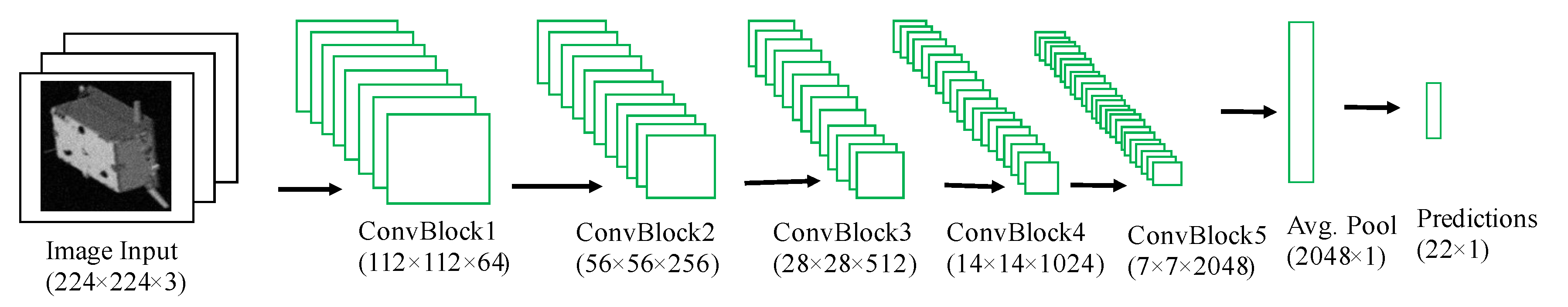
Figure 1 shows a typical CNN-based pose estimation flow.

2.2. Hardware Inference for Space Applications

While various space applications, including pose estimation, can benefit from deep learning, they face challenge in suitable hardware for inference. Small satellites have limited power, mass, and cost budgets, which poses computing power challenges compared to terrestrial applications. The space environment also offers challenging conditions for the operation of electronics. Lu et al. in [23] review the effects of space environment in different orbits. They observe that a spacecraft is mainly affected by the following space components: neutral atmosphere, plasma, radiation, macroscopic particles, geomagnetic, and temperature fields. LEO is predominantly influenced by radiation and macroscopic particles, whilst MEO and GEO are greatly exposed to solar activities, plasma environment, and radiation. Approximately, radiation anomalies and temperature-induced anomalies account for 40% and 11% of spacecraft failures in the space environment, respectively [23].The main radiation sources in space include trapped radiation, galactic cosmic rays, and solar energy particles.
Damage to electronic devices on board spacecraft due to radiation is mainly categorized into ionizing and non-ionizing (displacement) damage. Displacement damage is the cumulative long term non-ionizing damage due to protons, electrons, and neutrons. Ionization damage is the creation of electron-hole pairs and it can be further categorized into total ionizing dose (TID) and single event effects (SEE). The former is the cumulative long term ionizing damage due to protons and electrons, whilst the latter is caused by a single charged particle such as heavy ions and protons [24,25]. The Tenkoh satellite that was developed at Kyushu Institute of Technology and launched in October 2018 was analyzed to have suffered SEEs after passing over the South Atlantic Anomaly [26].
Due to these harsh conditions in space, radiation-tolerant, radiation-hardened, and space-grade computing hardware is desirable for space operations. This has limited the options available for hardware suitable for inference in space. Nevertheless, there is hardware with flight heritage that is very amenable to on-board inference. This section explores such computing hardware that is based on flight heritage or planned missions, support for CNN inference, and other factors, such as low power consumption. These are summarized in Table 1.
This survey reveals that hybrid computing devices comprising FPGAs and Systems-on-Chips (SoCs) are preferred for implementing machine and deep learning algorithms onboard spacecraft. However, most of these are not space-grade devices. George et al. in [27] identified hybrid and reconfigurable computing as driving the revolutionary capabilities of small satellites such as cubesats. Lentaris et al. in [28] conducted a review of high-performance embedded computing for vision-based navigation in space based on four categories: FPGA, CPU, GPU, and DSP. They found that FPGAs achieved the highest performance per watt of all platforms by at least one order of magnitude. GPUs are power hungry when compared to FPGAs and CPUs for comparable operation and accuracy [28]. CPUs performance fade in comparison to FPGAs in DL inference. Consequently, FPGAs are more suitable for space inference-based applications. Additionally, they are already being used in mission-specific and satellite subsystem operations. They are also reconfigurable and, therefore, can be adopted for different tasks on the fly.
In May 2020, Xilinx unveiled the Xilinx® Radiation Tolerant (RT) Kintex® UltraScale™ XQRKU060 FPGA. The device is optimized for various computational-intensive space applications. It is the first 20 nm space-grade FPGA optimized for machine learning inference coupled with unlimited on-orbit reconfiguration for real time on-board-processing. Some of its key applications include on-board AI for autonomous space exploration, real-time streaming of earth observation, remote sensing video, and for flexible, digital beam-forming telecommunication satellites [29]. In September 2020, ESA launched the Phi-sat-1 satellite that incorporated AI for Earth observation. Intel’s Myriad 2 Vision Processing Unit was used as the onboard inference platform, although it is not space-grade. This hardware was incorporated to utilize deep CNN in automatic cloud cover identification. Synthetic data from existing missions were used as the training data. It is the first European satellite to demonstrate how onboard artificial intelligence can improve the efficiency of sending EO data back to Earth. Initial data downlinked from the satellite showed successful assortment of the hyperspectral imagery into cloudy and non-cloudy pixels [30]. This preceding hardware survey informed the decision to pick the Xilinx Zynq UltraScale+ MPSoC for onboard CNN inference. This is because its programmable logic can be comparable to the XQRKU060 FPGA logic, as presented later in Table 6.

2.3. FPGA-Based Inference Accelerators

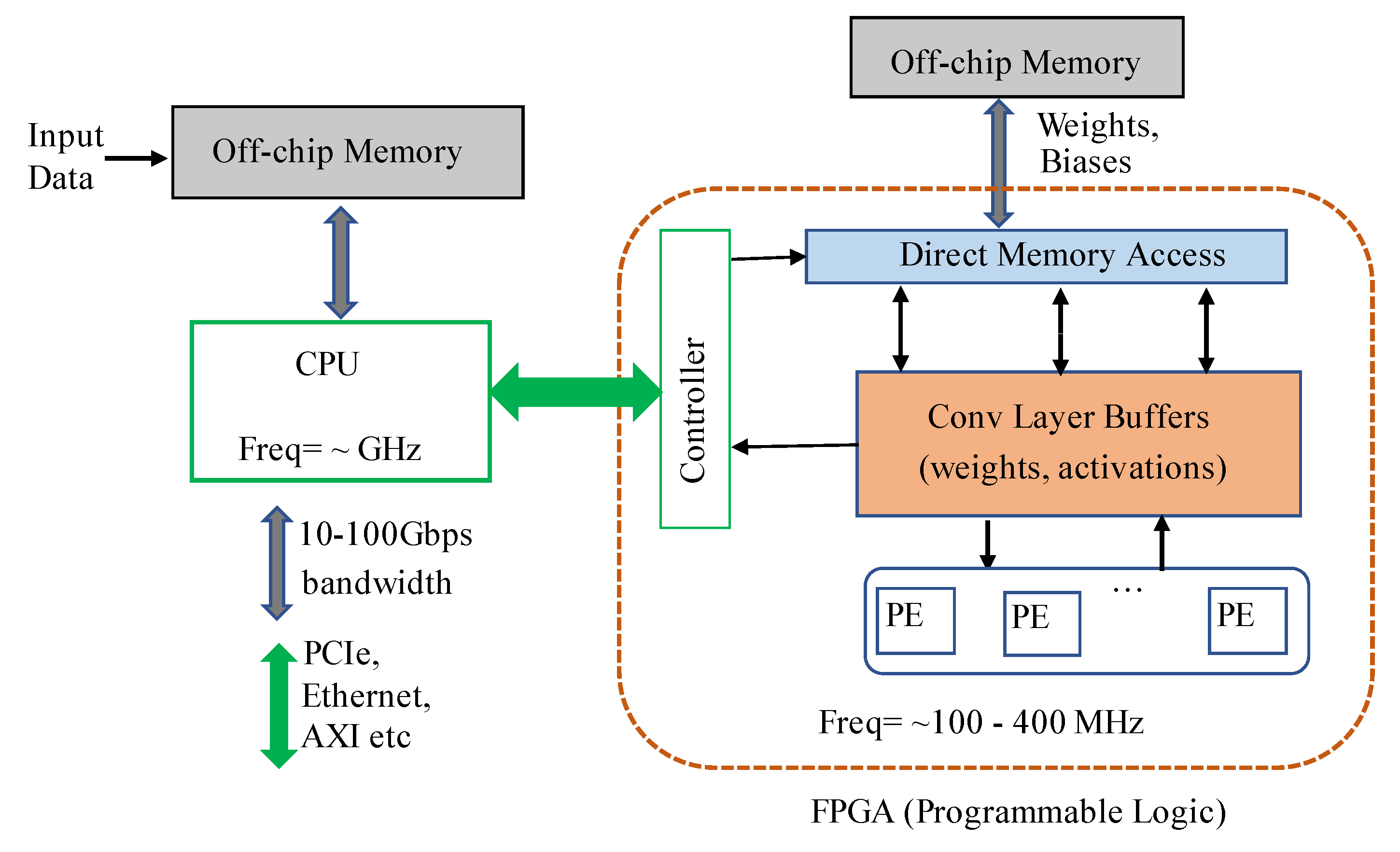
In terrestrial applications, FPGAs have been investigated and utilized as inference accelerators in deep and machine learning applications. The inherent parallelism of FPGAs has been instrumental in achieving real-time inference for such applications. The evaluation boards used in FPGA-based inference have hybrid CPU + FPGA heterogeneous architecture. The Programmable Logic (PL) is the FPGA chip and it contains the computing complex, processing elements, on-chip buffers, controller, and the DMAs. The Processing System (PS) consists of the CPU and external memory. Most of the FPGA-based accelerators have been specific to different CNN architectures and models. Figure 2 shows a typical accelerator that is based on FPGA. The CNN inference is performed in the PL side, whilst a CPU is required for pre-and post-processing and scheduling tasks. An external memory is required to store the CNN model parameters, data, and instructions. A full CNN model comprises of both convolutional (CONV) and fully-connected (FC) layers. The former are computational-intensive, whilst FC layers are memory-centric, as they typically contain millions of weights. Basic architectures of FPGA-based accelerators can be grouped in three categories: (i) single processing engine, usually in the form of a systolic array that processes each layer sequentially; (ii) streaming architecture that consists of one Processing Element (PE) per network layer; and, (iii) vector processor with instructions that are specific to accelerating the primitive operations of convolutions.
Guo et al., in [31], conducted a survey on FPGA-based NN inference accelerators. They note that the main considerations for such accelerators is high speed (high throughput and low latency) and high energy efficiency. One of the key steps in adopting models for FPGA inferencing is reducing the network size i.e., model compression. This can be achieved by approaches. such as data quantization and weight reduction, via methods such as pruning. The survey also explores the various hardware design methodologies that have been adopted for efficient architecture, including computation unit designs, loop unrolling strategies and the overall system design taking into account CPU, FPGA and memory configurations. It also investigates the different automation approaches for mapping networks to hardware i.e., hardware and software design automation.
Dinelli et al. presented one example of hardware design methodology in [32], where they implemented a MEM-OPT system to address the on-chip memory bottleneck of FPGA-based hardware accelerators. The MEM-OPT system is composed of three design aspects: a scheduling algorithm, a Secondary Cache System (SCS) for data re-use and support for different configurations. The scheduler determines the number of elements read out of the Input Cache (IC) for efficient on-chip memory usage. The SCS memory enables IC data re-use, hence reducing the amount of data read out the IC, because successive convolution operations share part of the input data previously read. The MEM-OPT does not require output buffer, because each processing element computes only one output value at a time. This system showed considerable reduction of on-chip memory (BRAMs) usage when compared to other scheduling algorithms.
Wei et al., in [33], implemented CNN on FPGA while using systolic array architecture for high throughput. This approach ensures low global data transfer since the processing elements (PEs) do not need to access the on-chip memory. Instead, connections are only required between different computation units for data transfer. This systolic architecture enables achievement of high frequency even in massive parallelization with hundreds of PEs. They also implemented an automated flow to map CNN architectures from high-level C code to FPGA, with no hardware-related, low-level considerations necessary for end-users. Lian et al. in [34] implemented an FPGA-based CNN model by adopting an optimized block floating-point (BFP) arithmetic. The BFP is composed of a mantissa part, whose bit length is defined as 8 for typical CNN models, and an exponent part. Quantization involves both FP2BFP and BFP2FP conversions.
Earlier quantization strategies had gone to as low as binary representation. Courbariaux et al., in [35], introduced a method of training such Binarized Neural Networks (BNNs). This enabled the use of binary weights and activations for computing the parameters gradients. This enables replacement of arithmetic operations with bit-wise operations, even during train-time, hence reducing training time, memory consumption, and increasing power-efficiency. During training, the weights and activations are constrained to either +1 or −1. Rastegari et al., in [36], implemented two efficient binary variations of convolutional neural networks. The first one, Binary Weight Networks, had all the weight values approximated with binary values whilst the second one, XNOR Networks, had both weight and input with binary values. The former led to 32x smaller networks when compared to equivalent networks with single-precision weight values and resulted in 2x speed up. The XNOR-Nets resulted in 58x speed up, whilst offering accurate approximation of CNNs. Umuroglu, in [37], presented a framework (named FINN) for building scalable and fast inference accelerators on FPGAs. They provide an end-to-end mapping of BNNs onto FPGAs. The FINN implementation uses separate compute engines that were dedicated to each layer and which communicate via on-chip data streams. Each engine starts to compute as soon as the previous engine starts to produce output. This framework was further improved into FINN-R that automated the creation of fully customized inference engines for quantized neural networks [38].
One of the seminal works on FPGA-based inference accelerators was presented by Qiu et al. in [39]. They implemented a CNN accelerator for the Image-Net large-scale image classification on the Xilinx Zynq ZC706 board.A major contribution was an automatic flow for 8/4 bit dynamic-precision data quantization. They used 8-bit and 16-bit fixed-point numbers for the onboard inference and achieved comparable results to floating-point implementations. This set the foundation for their next contribution in [40], where they present a hardware/software co-design flow for FPGA-based CNN implementation. The original network is compressed to fixed-point representation by optimizing the choice of the radix point positions for the network parameters in every layer. They also implement a parameterized and run-time configurable hardware architecture that supports various networks and that can be adopted on different hardware platforms. They also propose a compiler to map a CNN model to the hardware platform. This work led to the commercial FPGA accelerator engine, DeePhi [41], which was later acquired by Xilinx and improved into the Deep Neural Network Development Kit (DNNDK) package [42].
Previous accelerator engines had to be custom-designed for various networks and model applications. This had made the adoption of FPGAs as inference engine in real-world applications limited. However, the DNNDK package led to Xilinx introducing an Intellectual Property (IP) core, the Xilinx Deep Learning Processing Unit (DPU) [43]. This enhances the implementation of inference engines that are easily adaptable for different CNN architectures and models. Zhu et al., in [44], explored the DPU architecture and design flow by implementing an efficient task assignment framework to maximize performance on DPU-based CNN acceleration. They explored the optimization of task scheduling between the heterogeneous ARM CPU and multiple DPUs. The optimization strategy aims to utilize the DPU in otherwise unused interval time between multiple inference problems running on multiple threads.The optimization strategy also aimed to ensure that the inference tasks of different networks are controllable. The use of DPU has greatly been enhanced by Xilinx’s machine learning ecosystem that includes the Vitis-AI and model zoo.

3. Methodology

As presented in Section 1, this work focused on implementing the inference part for CNN-based pose estimation as depicted in Figure 3 which shows the architecture for adopting a typical CNN-based pose estimation flow on an FPGA-based platform. The SPEED dataset [11] is used for evaluation of this work flow. It consists of 12,000 synthetic images for training with an additional 2998 for testing. The images are for a 3D rendition of a spacecraft, as well as 300 real images of the same spacecraft model. All of the training images have a pixel resolution of 1920 × 1200. Google Colab was used in training the various networks due to the availability of GPU allocations at no cost. The 11 landmarks as presented in [21] were picked in this work as well to represent the 3D structure of the satellite. These are the eight corners of the satellite and tips of the three antennas.
This section presents the approach taken to realize onboard implementation of the FPGA inference part shown in Figure 3.

3.1. Regression vs. Detection-Based Approaches

In pose estimation problems, one of the key steps is the detection of pre-determined areas of the object, known as keypoints or joints. These are chosen apriori and when connected, they generally model the object and its orientation. Keypoints detection is therefore the determination of the precise pixel location of the target joint. In spacecraft pose estimation, the illumination conditions of the spacecraft vary greatly in orbit. The images can be bright with the sun in the background or they can be dark when the spacecraft is in the Earth’s shadow. The chosen keypoints are usually not all visible in the 2D image, some are occluded. Hence, the detection of the keypoints needs to be robust in both poor illumination conditions and occluded keypoints.
There are generally two major approaches to keypoints detection [45]. One is to directly regress the keypoint coordinates from an input image i.e., regression-based, whilst the other is to obtain coordinates from an intermediate heatmap i.e., detection-based. These two approaches make a tradeoff between the desirable traits of a deep learning model i.e., spatial generalization and end-to-end differentiability. The former is the ability of a network to generalize knowledge obtained at a particular location during the training phase to a different location during inference. The latter is a characteristic of the model to be composed of fully differentiable layers in an end-to-end manner that allows for backpropagation training.
In direct regression of keypoints, end-to-end differentiability is the driving factor. The input is the 2D image and the desired coordinates are the outputs. This approach has been used to varying success in human pose estimation problems, including the seminal work “DeepPose” by Toshev and Szegedy in [46]. The output layer predicts a pose/coordinate vector by minimizing a loss function that is usually the L 2 (mean square error) distance between the prediction and ground truth pose/coordinates. Hence, the network directly regresses the x , y coordinates of the keypoints.
In the detection-based approach, the output layer predicts a heatmap as opposed to coordinates. The loss function minimizes the error between the predicted and ground truth heatmaps. The coordinates are then extracted from the heatmaps in a post-processing step, which is usually to find the location p in the heatmap H n with maximum likelihood for the keypoint K n , as shown in Equation (5).
K n = argmax p H n ( p )
where K n is the nth keypoint and H n is the corresponding predicted heat map for nth keypoint. Because the end goal is the coordinates, this approach loses the end-to-end differentiability as this equation is not differentiable. Nevertheless, this detection-based approach is more effective than the regression-based approach since its training is supervised by dense pixel information, as will be demonstrated in this work. This approach was first utilized by Tompson et al. in [47]. The target heatmap was a 2D Gaussian with a small variance and mean centered at the ground-truth coordinate locations. This approach has been improved over the years, notably by the stacked hourglass network by Newell et al. in [48]. The main feature of the hourglass is the symmetry between the bottom-up processing (from high to low resolutions) and top-down processing (from low to high resolutions). For every layer on the way down, there is a corresponding layer going up. The full network is realized by stacking multiple hourglasses. The output of the network is a set of heatmaps that are a prediction of the probability of a joint’s presence at every pixel. Consequently, smilar approaches have been used in works, such as [49,50].

3.2. Network Model Architectures

The key criteria for selection of the network models in this work are based on their amenity to FPGA acceleration on the Zynq UltraScale+ MPSoC. Since the ultimate goal of this work was to investigate the acceleration of the CNN-part of pose estimation algorithms on FPGA, it is essential that the network layers and operations are supported by the DPU. More so, the operations need to be supported by the model quantization as well as compilation tools that are required for preparing the model for inference on Xilinx FPGAs. Table 2 shows operations that are supported by the Xilinx DPU and any imposed limitations.
Three approaches were taken in this work as presented in the following sections.

3.2.1. Approach 1: Direct Regression on Full Image

ResNet-50 model architecture is utilized in this approach. The SPEED dataset used in this evaluation has images with pixel size of 1920 × 1200. In this first approach, direct regression with no prior pre-processing, such as cropping, is adopted. The images are only resized to 224 × 224 to fit the input size of the ResNet model. This makes it more difficult for the network to detect as well as learn the spatial features of the spacecraft within such a small footprint. Nevertheless, the focus of this research is mainly based on the detection-based approaches that will be presented in the next sections. Because there are 11 keypoints, the network output needs an output vector of size 1 × 22. To achieve this, a global average pooling layer was added after the fifth block, before the output is finally fed into a fully connected (dense) layer with 22 units that gives the final keypoint predictions. Figure 4 depicts this network architecture.
The network was trained on Google Colab while using an allocated Tesla GPU. It was trained for 40 epochs in batches of 32. 8000 images were used for training, 1800 for validation, and 200 for testing. Figure 5 shows the performance of the network after 40 epochs. The network here is expected to localize the spacecraft within the image and then learn the spatial coordinates of the spacecraft keypoints. As expected, the performance is poor. As earlier noted, this could be improved by more training and use of more data. Nevertheless, the performance of regression-based approaches would still be poor. Its keypoint detection RMS-Error was highly erratic, with values ranging from 60 to 70. Hence, this approach was not developed further.

3.2.2. Approach 2: Detection (Heatmap-Based) on Full Image

U-Net model architecture is used in this approach. The U-Net is a detection-based network, in that, instead of directly regressing the keypoints, it outputs a heatmap for each of the keypoints. Figure 6 shows this architecture approach. Similar to the ResNet-50 based direct regression, the U-Net network was trained on uncropped images i.e., the full resolution of 1920 × 1200 training dataset images. They were resized to 224 × 224. The network was trained over 40 epochs. The performance of this detection-based approach was much better than the direct regression even though they were both trained on the full image sizes and over the same training epochs.
Figure 7 shows the U-Net model performance on the uncropped images. Though the performance is still poor, it is significantly better than the ResNet50 based direct regression. Its keypoint detection RMS Error is averagely two times less than the one based on ResNet50.

3.2.3. Approach 3: Spacecraft Detection, Cropping and Heatmap-Based Detection

The main focus of this paper is on the inference for the CNN part of CNN-based pose estimation methods, as introduced in Section 3. To achieve high accuracy in pose estimates, a corresponding high accuracy in landmark detection is required. Hence, in this approach, a framework for achieving high accuracy in keypoint detection is presented. The performance of the keypoint detection is greatly increased by first detecting the spacecraft within the image. The spacecfraft within the image is first detected, as shown in Figure 8. The image is then cropped around the detected box and the keypoint detection network is run on this bounded/cropped image. This approach greatly increases the accuracy of the keypoint detection when compared to the preceding two approaches.

3.2.3.1. YOLOv3

The YOLOv3 network is trained for the spacecraft detection phase. The choice of this network is due to its robust and effective performance in many real-time object detection applications [51]. It detects the spacecraft with a single forward pass through the network, hence its fast and efficient. This is very amenable to FPGA implementation and it is supported by Xilinx DPU IP core. The network is trained on a single class, named s a t e l l i t e , since we are only detecting the satellite object within the image. It is trained with the default 9 anchor boxes. The input images are of size 1920 × 1200. YOLOv3 resizes them to 416 × 416, detects the object and outputs the bounding box coordinates with the original size as the reference. The images in Figure 9 show performance of the YOLOv3 network in detecting the spacecraft. Though the confidence level is not critical in this application, it shows that the network can detect the spacecraft in varying illumination conditions such as cloudy background.
Once the spacecraft has been detected and the bounding box coordinates obtained, the image is cropped along the bounding box and fed into the keypoint detection network. This ‘zooming in’ of the image greatly improves the performance of the keypoint detection algorithms, which, in turn, will improve the pose estimation accuracy. Table 3 shows the ground truth bounding boxes coordinates with the corresponding Yolo-detected bounding boxes. After the spacecraft detection, the images are cropped along the bounding box coordinates and then fed into the keypoint localization network.

3.2.3.2. U-Net

The U-Net model presented in Section 3.2.2 is also utilized in this section. The model utilizes downsampling and upsampling. In down-sampling, the architecture follows a contracting path that captures context. Upsampling is symmetrical to the downsampling path and it is an expanding path that enables precise localization. With the output being heatmaps that rely on pixel localization, the output resolution needs to be high enough to enable accurate localization. Upsampling operators increase the output resolution, leading to greater accuracy in localization. The network is light and fast, making it suitable for onboard FPGA inferencing.
The image input is a cropped image that contains the spacecraft body as detected by the YOLO network in the preceding Section 3.2.3.1. The image is resized to 128 × 128 and fed into the U-Net model. This input size will determine the output dimensions. A large input size results in a corresponding high output resolution which leads to higher memory requirements during training. Hence, a compromise between the resolution and memory budget is required. The output resolution (and input image size) is chosen to be 128. The network is trained over 40 epochs in batches of 16 on Google Colab. The images in Figure 10 show the performance of the U-Net model in keypoint localization on cropped images. This performance on cropped images is greatly superior to the same model’s performance on uncropped images, as previously presented in Figure 7.

3.2.3.3. ResNet34-U-Net Model

The performance in keypoint localization can further be improved by a slightly modified decoder-encoder architecture. In this section, a ResNet34-U-Net model is explored. The encoder (downsample) part of the network is implemented as ResNet-34. The decoder (upsample) is implemented as the U-Net upsample part. The skip connections from the ResNet-34 are picked at the layers, as shown in Table 4.
This model architecture has the highest accuracy performance, hence was picked for the onboard inference implementation. A key aspect in the choice of this network, in addition to its accuracy performance, is that its layers and operations are supported by Xilinx DPU. Figure 11 shows the model architecture, whilst its performance is presented in Figure 12.

3.2.3.4. Summary on Network Models

From the above implementations, the following is noted:
  • Detection-based algorithms have higher accuracy compared to regression-based approaches.
  • Detecting the spacecraft and inputting the detected area into the landmarks localization algorithms greatly increases its accuracy.
  • Decoder-encoder networks have the highest accuracy with the ResNet34-U-Net model exhibiting a slightly higher accuracy compared to the basic U-Net model.
From the preceding observations, the ResNet34 – U-Net model was chosen for the onboard inference implementation. Table 5 shows performance summary of the models that were investigated in this work.
The next section introduces the steps for configuring the network for onboard inference with Xilinx UltraScale+ MPSoC as the target device.

3.3. FPGA Inference

The target device for this implementation is the Xilinx Zynq UltraScale+ MPSoC. This family of devices incorporates both programmable logic (PL) and processing system (PS) on a single chip. MPSoC implies presence of multiple (and heterogeneous) processors. These chips include a real-time processing unit (RPU), which is a dual-core Arm Cortex-R5F, and an application processing unit (APU), which is a dual- or quad-core Arm Cortex-A53. The 64-bit APU enables high-level operating system support, e.g., Linux. The Ultra96v2 board is used as the evaluation board. It is a low cost board that incorporates the Zynq MPSoC and other essential peripherals. In a real space mission, the MPSoC device can be incorporated into a custom PCB design that only utilizes the necessary peripherals. This would result in an optimal implementation that meets the key aspect of this work: onboard inference hardware that is small, low-power, and low-cost for satellite operations. Table 6 shows resource comparison of various Xilinx FPGAs and MPSoC devices. The Ultra96v2 board contains the ZU3EG MPSoC.
Figure 13 shows the flow for training and adapting the models for onboard inferencing. Network training has been presented in the preceding sections. This section will focus on the hardware and software implementation on the Zynq MPSoC device in order to achieve onboard inference. This section will briefly introduce the DPU architecture and present the pipeline for developing inference accelerators that incorporate it in FPGA applications.

3.3.1. Xilinx DPU IP Core

Deep-learning Processing Unit (DPU) is a Xilinx IP core for implementing FPGA-based inference accelerators of deep learning architectures. It is a configurable computation engine that is optimized for convolutional neural networks [24]. It is intended for implementation in the programmable logic of Xilinx Zynq-7000 SoC and UltraScale+ MPSoC devices. It requires devices with direct connections to a processing system. For its operation, it requires an application processing unit that services interrupts from the DPU core and coordinates data transfers between the DPU core and other peripherals. It also needs access to memory locations, such as RAM for input images, temporary, and output data. The core of the DPU is made of processing elements that consist of FPGA building blocks, such as multipliers, adders, and accumulators.
DPU IP can be configured for the optimized implementation of various CNN architectures. Some of the user-configurable parameters are briefly presented here. The first parameter is the number of DPU cores that can be instantiated in the FPGA fabric. A maximum of three cores can be instantiated in a single DPU IP. An increase in the number of cores results in increased consumption of PL resources and power requirements. Another parameter for DPU customization is the convolution architecture. The Xilinx IP offers eight architectures to choose from. These are B512, B800, B1024, B1152, B1600, B2304, B3136, and B4096. These architectures are based on the three dimensions of parallelism in the DPU convolution architecture: pixel, input channel, and output channel parallelisms. RAM usage is another parameter that can be configured to set the total amount of on-chip memory that can be used in different DPU architectures. This on-chip memory is for buffering weights, bias, and intermediate network features.

3.3.2. Zynq MPSoC Hardware and Software Implementation

Hardware design is implemented in Xilinx Vivado IDE. The DPU IP is instantiated in appropriate configurations in order to meet the ResNet34-U-Net network architecture. In addition to the DPU IP, other IPs, such as Zynq MPSoC, Processor System, Clock Wizard, and others, are also instantiated to meet the hardware requirements for a fully operational device. Vivado enables the instantiation of IPs in the PL part of the device. The PS part is accessed from the software development side/phase. Figure 14 shows the block design in Vivado. The hardware design is synthesized and implemented. A bitstream file is generated and the hardware design is exported to be used as the base hardware upon which the software is built. Data between the PS and PL regions is exchanged via the PS-PL interface, which is AXI4-based. In a real system, the input data would be obtained from a camera. However, in this implementation, the images are stored in an SD card, from which the PS accesses via the linux file system and then inputs them to the DPU during inference. The PS has other input/output peripherals, such as USB, UART, DisplayPort, etc., which enable data input and visualization on external displays. These interfaces are also exposed by the Ultra96v2 board.
Yocto/Petalinux is used to generate a custom Linux image that incorporates the deep learning aspect of the project. Xilinx DNNDK tool, which is required to deploy neural networks on the DPU, is incorporated as a package in the Yocto flow. DNNDK is a full stack deep learning tool-chain for inference with the DPU and it is composed of the following components: Deep Compression Tool (DECENT), Deep Neural Network Compiler (DNNC), Neural Network Runtime (N2 Cube) and DPU Profiler. The DPU instructions which are closely tied to the DPU architecture, target Neural Network and the AXI data width are generated offline using DNNC. This results in an Executable Linker File (ELF), which is then compiled together with other custom C/C++ program instructions that control other tasks of the deep learning algorithm, such as loading of images, visualization, and other pre-processing tasks. The CPU and DPU elf files are then compiled into a single file that is loaded into the MPSoC. Figure 15 shows the flow for hardware, Linux image generation and the flow for DPU-based deep learning implementation.

3.3.3. ResNet34-U-Net Architecture Inference Implementation

Network Freezing

The first step in preparing the trained network for inference is to freeze it after training. During training, a model stores not only the trainable weights, but also metadata that are essential in the training phase. However, for inference, these metadata are not required. Hence, freezing the network achieves two main objectives: the weights are ‘frozen’ i.e., made untrainable and metadata not required for inference is removed. This results in a light-weight model graph that is efficient for inference.

Network Quantization

The frozen weights and graph variables are in a floating point. Many deep learning models have tens of millions of weights and, thus, floating-point representation results in huge data size. For inferencing, especially on edge devices such as FPGAs, there is limited memory for weights and data storage. The weights can be converted to lower precision and fixed-point representation such as 4-bit, 8-bit, or 16-bit integer representation. This greatly reduces the size of the data and overall model size, with little degradation in the model accuracy. Xilinx utilizes INT8 and INT4 optimization in its DSP48E2 slices for deep learning operations in the DPU. Quantization improves on memory bandwidth and power efficiency.
Xilinx provides the d e c e n t _ q tool for quantization purposes. It takes the frozen graph as input. The key parameters for d e c e n t _ q are the input and output nodes, input shape and the pre-processing input function. It also requires a few images for calibrating the quantized network. A deploy model is generated after successful calibration. In the deploy model, the upsample layers are implemented by Xilinx’s custom D e e p h i R e s i z e layers. The rest of the layers, have similar implementation to the frozen Tensorflow models.This is ready for the next phase of compiling i.e., generating the executable linker files.

Network Compilation

After quantization, the network is compiled for deployment to the hardware (DPU). The Deep Neural Network Compiler (DNNC) is used in order to generate ELF files and kernel information for deployment. The information gives a summary of the layers and operations that have been compiled for DPU and the operations that need to be deployed on the CPU side. Operations, such as softmax, sigmoid, and average pooling, are best suited for CPU deployment; hence, DNNC does not compile them into the ELF files. Figure 16 shows the deploy model that is generated in the quantization stage and the DNNC output of the compilation stage.

Network Deployment

The hardware and software flow that is presented in Section 3.3.2 and Figure 15 is followed for the deployment to the MPSoC device. There are mainly two approaches for deployment to the FPGA board. One is to use the DNNDK tools directly in the Xilinx SDK by incorporating the DPU ELF file into a C/C++ application. The other is to use the Vitis-AI flow that greatly eases the deployment process. The latter has support for both Python scripts and C++ applications for the CPU side. The use of Petalinux on the CPU side also enhances the integration between the CPU and DPU architectures. Vitis-AI provides Python and C++ APIs, at both the high-level and low-level. The latter enables closer manipulation of the DPU engine. This includes DPU kernel and task creation and destruction; the manipulation of DPU input and output tensors; and, the deployment of DPU un-supported operations to the CPU side. These APIs also enable implementation of pre-processing of input data and post-processing output data for the DPU. The sigmoid part of the network is implemented on the CPU side in a Python script. The output has 11 channels representing the heatmaps for each of the 11 keypoints. This is reshaped on the CPU side into a single channel i.e., single heatmap.

4. Inference Results

Various results were presented in the preceding sections at every step of the methodology. In this final result section, the performance of the Ultra96v2-based inference and that of a PC-based inference is presented. The keypoint coordinates that were obtained from the onboard-inference were superimposed on those from the PC-inference. 100 test images were used for the inference testing phase. Figure 17 shows these results.
Table 7 presents the performance of the FPGA-based (8-bit quantized) inference as compared to PC-based (float) inference. It is shown that, although the inference on the MPSoC device is implemented with 8-bit quantization, there is no significant loss of accuracy from the PC-based implementation that uses 32-bit floats, with an average keypoint detection RMS error difference of less than 0.55. Hence, the hybrid Zynq MPSoC device is a viable candidate for implementing onboard inference in CNN-based spacecraft pose estimation algorithms.
In addition to network RMS error performance, another key factor for consideration is the resource utilization of the FPGA fabric. The DPU is optimized for deep learning inference; hence, deep networks can be implemented on it without excessive resources. DPU resource utilization is dependent on its configuration parameters. The IP can be configured up to three cores. However, the target MPSoC device on the Ultra96v2 board is not sufficient for accommodating the corresponding high resource utilization. Only one core of the DPU was implemented in this work. Table 8 shows the resource utilization for different configurations of the DPU-based implementation.
Power consumption is another key factor to consider for onboard inference in space applications. Table 9 shows the on-chip power consumption estimates for different DPU configurations as estimated using the Report Power tool in Vivado IDE. This is an estimate of the total on-chip power consumed internally within the MPSoC device. It does not include power consumed by other off-chip devices and peripherals on the Ultra96v2 board. Figure 18 shows the evaluation board power consumption with no inference and during inference. It can be seen that the board consumes about 6.84 W when no inference job is running and about 8.16 W during inference. Hence, it can be concluded that the inference task consumes approximately 1.32 W. However, in a real mission, the MPSoC chip will be incorporated on a custom PCB with only the necessary peripherals as opposed to the full-blown circuit on the evaluation board used in this work. Therefore, the power consumption for such a custom board will be significantly less than that of the Ultra96v2 evaluation board.

5. Discussion and Conclusions

This work has presented the implementation of an FPGA-based onboard inferencing of CNN-based spacecraft pose estimation. The focus of this paper is in accelerating the CNN part of such a pose estimation flow i.e., the landmark/keypoint localization for the 3D spacecraft structure. Once the landmarks have been localized, the rest of the pose estimation flow can be performed on the CPU part. Previous studies have focused on general PC-based implementation without exploring how such algorithms can be adapted to real-case applications. In this paper, the Zynq MPSoC has been proposed as a suitable device for realizing onboard inference. A complete flow for such an implementation has been presented in this paper, beginning from network training, freezing, quantization, compilation, and, eventually, deployment to the board.
Direct regression and detection-based landmark localization were investigated. The former had poor performance when compared to the latter. Encoder-decoder model architectures were found to have better landmark localization performance. Of these, the ResNet34-U-Net model was found to have higher accuracy than a pure U-Net model. The performance was greatly enhanced by first detecting the spacecraft within the image. YOLOv3 was used for this detection and the image was cropped along the bounding box. The landmark localization network was then fed the cropped image as input. This approach was found to have superior accuracy with an average RMS error of 1.7896 as compared to the uncropped approach performance of an average RMS error of 26.4587.
Xilinx UltraScale+ MPSoC was used as the target device. Its average on-chip power consumption of 3.5 W is low enough for power-limited spacecrafts and satellites. It should be noted that the evaluation board used in this work contains numerous extra peripherals and components that add to the overall power consumption. A custom design utilizing the MPSoC chip and off-chip memory would be suitable for a real space mission. Vivado was used for the hardware design i.e., programmable logic design. DPU IP core was utilized in order to implement the inference engine.It is configurable for various network types and supports most of the operations in typical CNN architectures. This is very convenient for adapting it to different spacecraft operations and not only pose estimation. It is shown that the onboard implementation accuracy is comparable to the PC-based inference, with an average RMS error difference of 0.531.
This work can further be developed in order to achieve an end-to-end FPGA-based spacecraft pose estimation. This will include interfacing to a real-time camera and performing the CPU-based algorithms for the final pose estimation tasks. The current implementation runs the two networks, YOLOv3 and ResNet34-U-Net, as standalone. The cropped images from the detection phase are stored in memory from which the DPU reads and runs them through the landmark localization phase. In an end-to-end implementation, these two phases would be coupled together. The inference time would be accurately measured in such an end-to-end implementation and it is estimated to be in tens of milliseconds that is consistent with other applications that have used Xilinx DPU in their designs.

Author Contributions

Conceptualization, K.C. and A.K.; methodology, K.C.; software, K.C.; validation, K.C. and A.K.; formal analysis, K.C.; investigation, K.C.; resources, X.X.; data curation, K.C.; writing–original draft preparation, K.C.; writing–review and editing, K.C.; visualization, K.C.; supervision, A.K.; project administration, A.K.; funding acquisition, A.K. All authors have read and agreed to the published version of the manuscript.

Funding

This research received no external funding.

Conflicts of Interest

The authors declare no conflict of interest.

Abbreviations

The following abbreviations are used in this manuscript:
APUApplication Processing Unit
AXIAdvanced eXtensible Interface
BNNBinarized Neural Networks
CNNConvolutional Neural Network
FPGAField Programmable Gate Arrays
DMADirect Memory Access
DPUDeep Learning Processing Unit
DNNDKDeep Neural Network Development Kit
DNNCDeep Neural Network Compiler
ELFExecutable Linker File
GEOGeosynchronous Equatorial Orbit
IDEIntegrated Design Environment
IPIntellectual Property
LEOLow Earth Orbit
MEOMedium Earth Orbit
MPSoCMulti-Processor System-on-Chip
PCBPrinted Circuit Board
PLProgrammable Logic
PSProcessing System
SEESingle Event Effect
TIDTotal Ionizing Dose

References

  1. Woellert, K.; Ehrenfreund, P.; Ricco, A.J.; Hertzfeld, H. Cubesats: Cost-effective science and technology platforms for emerging and developing nations. Adv. Space Res. 2011, 47, 663–684. [Google Scholar] [CrossRef]
  2. Foreman, V.L.; Siddiqi, A.; De Weck, O. Large satellite constellation orbital debris impacts: Case studies of oneweb and spacex proposals. In AIAA SPACE and Astronautics Forum and Exposition; 2017; p. 5200. Available online: https://arc.aiaa.org/doi/abs/10.2514/6.2017-5200 (accessed on 25 July 2020).
  3. Petit, A.; Marchand, E.; Kanani, K. Tracking complex targets for space rendezvous and debris removal applications. In Proceedings of the 2012 IEEE/RSJ International Conference on Intelligent Robots and Systems, Vilamoura, Portugal, 7–12 October 2012; pp. 4483–4488. [Google Scholar]
  4. Aslanov, V.; Yudintsev, V. Dynamics of large space debris removal using tethered space tug. Acta Astronaut. 2013, 91, 149–156. [Google Scholar] [CrossRef]
  5. Shan, M.; Guo, J.; Gill, E. Review and comparison of active space debris capturing and removal methods. Prog. Aerosp. Sci. 2016, 80, 18–32. [Google Scholar] [CrossRef]
  6. Flores-Abad, A.; Ma, O.; Pham, K.; Ulrich, S. A review of space robotics technologies for on-orbit servicing. Prog. Aerosp. Sci. 2014, 68, 1–26. [Google Scholar] [CrossRef] [Green Version]
  7. Whelan, D.A.; Adler, E.A.; Wilson, S.B., III; Roesler, G.M., Jr. Darpa orbital express program: Effecting a revolution in space-based systems. Small Payloads Space 2000, 4136, 48–56. [Google Scholar]
  8. Nanjangud, A.; Blacker, P.C.; Bandyopadhyay, S.; Gao, Y. Robotics and AI-enabled on-orbit operations with future generation of small satellites. Proc. IEEE 2018, 106, 429–439. [Google Scholar] [CrossRef]
  9. Bajracharya, M.; Maimone, M.W.; Helmick, D. Autonomy for mars rovers: Past, present, and future. Computer 2008, 41, 44–50. [Google Scholar] [CrossRef] [Green Version]
  10. Wong, C.; Yang, E.; Yan, X.T.; Gu, D. Adaptive and intelligent navigation of autonomous planetary rovers—A survey. In Proceedings of the 2017 NASA/ESA Conference on Adaptive Hardware and Systems (AHS), Pasadena, CA, USA, 24–27 July 2017; pp. 237–244. [Google Scholar]
  11. European Space Agency. Pose Estimation Challenge. Available online: Https://kelvins.esa.int/satellite-pose-estimation-challenge/home/ (accessed on 3 August 2019).
  12. Diebel, J. Representing attitude: Euler angles, unit quaternions, and rotation vectors. Matrix 2006, 58, 1–35. [Google Scholar]
  13. Yang, Y. Spacecraft attitude determination and control: Quaternion based method. Annu. Rev. Control. 2012, 36, 198–219. [Google Scholar] [CrossRef]
  14. Mukundan, R.; Ramakrishnan, K.R. A quaternion solution to the pose determination problem for rendezvous and docking simulations. Math. Comput. Simul. 1995, 39, 143–153. [Google Scholar] [CrossRef]
  15. Opromolla, R.; Fasano, G.; Rufino, G.; Grassi, M. A review of cooperative and uncooperative spacecraft pose determination techniques for close-proximity operations. Prog. Aerosp. Sci. 2017, 93, 53–72. [Google Scholar] [CrossRef]
  16. D’Amico, S.; Benn, M.; Jørgensen, J.L. Pose estimation of an uncooperative spacecraft from actual space imagery. Int. J. Space Sci. Eng. 2014, 2, 171–189. [Google Scholar]
  17. Hirano, D.; Kato, H.; Saito, T. Deep Learning based Pose Estimation in Space. In Proceedings of the International Symposium on Artificial Intelligence, Robotics and Automation in Space (i-SAIRAS), Madrid, Spain, 4–6 June 2018. [Google Scholar]
  18. Sharma, S. Pose Estimation of Uncooperative Spacecraft Using Monocular Vision and Deep Learning. Ph.D. Thesis, Stanford University, Stanford, CA, USA, 2019. [Google Scholar]
  19. Phisannupawong, T.; Kamsing, P.; Torteeka, P.; Channumsin, S.; Sawangwit, U.; Hematulin, W.; Jarawan, T.; Somjit, T.; Yooyen, S.; Delahaye, D.; et al. Vision-Based Spacecraft Pose Estimation via a Deep Convolutional Neural Network for Noncooperative Docking Operations. Aerospace 2020, 7, 126. [Google Scholar] [CrossRef]
  20. Sharma, S.; Beierle, C.; D’Amico, S. Pose estimation for non-cooperative spacecraft rendezvous using convolutional neural networks. In Proceedings of the 2018 IEEE Aerospace Conference, Big Sky, MT, USA, 3–10 March 2018; pp. 1–12. [Google Scholar]
  21. Chen, B.; Cao, J.; Parra, A.; Chin, T.J. Satellite pose estimation with deep landmark regression and nonlinear pose refinement. In Proceedings of the IEEE International Conference on Computer Vision Workshops, Seoul, Korea, 27 October–2 November 2019. [Google Scholar]
  22. Sonawani, S.; Alimo, R.; Detry, R.; Jeong, D.; Hess, A.; Amor, H.B. Assistive Relative Pose Estimation for On-orbit Assembly using Convolutional Neural Networks. arXiv 2020, arXiv:2001.10673. [Google Scholar]
  23. Lu, Y.; Shao, Q.; Yue, H.; Yang, F. A review of the space environment effects on spacecraft in different orbits. IEEE Access 2019, 7, 93473–93488. [Google Scholar] [CrossRef]
  24. Martines S, L.M. Analysis of LEO Radiation Environment and Its Effects on Spacecraft’s Critical Electronic Devices. 2011. Available online: http://commons.erau.edu/cgi/viewcontent.cgi?article=1101&context=edt (accessed on 21 August 2020).
  25. NASA. The Radiation Environment. Available online: https://radhome.gsfc.nasa.gov/radhome/papers/apl_922.pdf (accessed on 21 August 2020).
  26. Fajardo, I.; Lidtke, A.A.; Bendoukha, S.A.; Gonzalez-Llorente, J.; Rodríguez, R.; Morales, R.; Faizullin, D.; Matsuoka, M.; Urakami, N.; Kawauchi, R.; et al. Design, Implementation, and Operation of a Small Satellite Mission to Explore the Space Weather Effects in LEO. Aerospace 2019, 6, 108. [Google Scholar] [CrossRef] [Green Version]
  27. George, A.D.; Wilson, C.M. Onboard processing with hybrid and reconfigurable computing on small satellites. Proc. IEEE 2018, 106, 458–470. [Google Scholar] [CrossRef]
  28. Lentaris, G.; Maragos, K.; Stratakos, I.; Papadopoulos, L.; Papanikolaou, O.; Soudris, D.; Lourakis, M.; Zabulis, X.; Gonzalez-Arjona, D.; Furano, G. High-performance embedded computing in space: Evaluation of platforms for vision-based navigation. J. Aerospace Inf. Syst. 2018, 15, 178–192. [Google Scholar] [CrossRef]
  29. Xilinx. RT Kintex UltraScale FPGAs for Ultra High Throughput and High Bandwidth Applications; White Paper; Xilinx: San Jose, CA, USA, 2020. [Google Scholar]
  30. ESA. Phi-Sat 1 Mission. Available online: https://www.esa.int/Applications/Observing_the_Earth/Ph-sat (accessed on 2 October 2020).
  31. Guo, K.; Zeng, S.; Yu, J.; Wang, Y.; Yang, H. [DL] A survey of FPGA-based neural network inference accelerators. ACM Trans. Reconfigurable Technol. Syst. 2019, 12, 1–26. [Google Scholar] [CrossRef]
  32. Dinelli, G.; Meoni, G.; Rapuano, E.; Pacini, T.; Fanucci, L. MEM-OPT: A Scheduling and Data Re-Use System to Optimize On-Chip Memory Usage for CNNs On-Board FPGAs. IEEE J. Emerging Sel. Top. Circuits Syst. 2020, 10, 335–347. [Google Scholar] [CrossRef]
  33. Wei, X.; Yu, C.H.; Zhang, P.; Chen, Y.; Wang, Y.; Hu, H.; Liang, Y.; Cong, J. Automated systolic array architecture synthesis for high throughput CNN inference on FPGAs. In Proceedings of the 54th Annual Design Automation Conference 2017, Austin, TX, USA, 18–22 June 2017; pp. 1–6. [Google Scholar]
  34. Lian, X.; Liu, Z.; Song, Z.; Dai, J.; Zhou, W.; Ji, X. High-performance fpga-based cnn accelerator with block-floating-point arithmetic. IEEE Trans. Very Large Scale Integr. Syst. 2019, 27, 1874–1885. [Google Scholar] [CrossRef]
  35. Courbariaux, M.; Hubara, I.; Soudry, D.; El-Yaniv, R.; Bengio, Y. Binarized neural networks: Training deep neural networks with weights and activations constrained to+ 1 or-1. arXiv 2016, arXiv:1602.02830. [Google Scholar]
  36. Rastegari, M.; Ordonez, V.; Redmon, J.; Farhadi, A. Xnor-net: Imagenet classification using binary convolutional neural networks. In European Conference on Computer Vision; Springer: Cham, Switzerland, 2016; pp. 525–542. [Google Scholar]
  37. Umuroglu, Y.; Fraser, N.J.; Gambardella, G.; Blott, M.; Leong, P.; Jahre, M.; Vissers, K. Finn: A framework for fast, scalable binarized neural network inference. In Proceedings of the 2017 ACM/SIGDA International Symposium on Field-Programmable Gate Arrays, Monterey, CA, USA, 22–24 February 2017; pp. 65–74. [Google Scholar]
  38. Blott, M.; Preußer, T.B.; Fraser, N.J.; Gambardella, G.; O’brien, K.; Umuroglu, Y.; Leeser, M.; Vissers, K. FINN-R: An end-to-end deep-learning framework for fast exploration of quantized neural networks. ACM Trans. Reconfigurable Technol. Syst. 2018, 11, 1–23. [Google Scholar] [CrossRef]
  39. Qiu, J.; Wang, J.; Yao, S.; Guo, K.; Li, B.; Zhou, E.; Yu, J.; Tang, T.; Xu, N.; Song, S.; et al. Going deeper with embedded fpga platform for convolutional neural network. In Proceedings of the 2016 ACM/SIGDA International Symposium on Field-Programmable Gate Arrays, Monterey, CA, USA, 21–23 February 2016; pp. 26–35. [Google Scholar]
  40. Guo, K.; Sui, L.; Qiu, J.; Yu, J.; Wang, J.; Yao, S.; Han, S.; Wang, Y.; Yang, H. Angel-Eye: A complete design flow for mapping CNN onto embedded FPGA. IEEE Trans. Comput.-Aided Design Integr. Circuits Syst. 2017, 37, 35–47. [Google Scholar] [CrossRef]
  41. Guo, K.; Sui, L.; Qiu, J.; Yao, S.; Han, S.; Wang, Y.; Yang, H. From model to FPGA: Software-hardware co-design for efficient neural network acceleration. In Proceedings of the 2016 IEEE Hot Chips 28 Symposium (HCS), Cupertino, CA, USA, 21–23 August 2016; pp. 1–27. [Google Scholar]
  42. Xilinx Inc. DNNDK User Guide. 2019. Available online: https://www.xilinx.com/support/documentation/sw_manuals/ai_inference/v1_6/ug1327-dnndk-user-guide.pdf (accessed on 26 September 2019).
  43. Xilinx Inc. DPU Product Guide. 2020. Available online: https://www.xilinx.com/support/documentation/ip_documentation/dpu/v3_2/pg338-dpu.pdf (accessed on 9 August 2020).
  44. Zhu, J.; Wang, L.; Liu, H.; Tian, S.; Deng, Q.; Li, J. An Efficient Task Assignment Framework to Accelerate DPU-Based Convolutional Neural Network Inference on FPGAs. IEEE Access 2020, 8, 83224–83237. [Google Scholar] [CrossRef]
  45. Nibali, A.; He, Z.; Morgan, S.; Prendergast, L. Numerical coordinate regression with convolutional neural networks. arXiv 2018, arXiv:1801.07372. [Google Scholar]
  46. Toshev, A.; Szegedy, C. Deeppose: Human pose estimation via deep neural networks. In Proceedings of the IEEE Conference on Computer Vision and Pattern Recognition, Columbus, OH, USA, 23–28 June 2014; pp. 1653–1660. [Google Scholar]
  47. Tompson, J.J.; Jain, A.; LeCun, Y.; Bregler, C. Joint training of a convolutional network and a graphical model for human pose estimation. In Proceedings of the Advances in Neural Information Processing Systems, Montreal, QC, Canada, 8–13 December 2014; pp. 1799–1807. [Google Scholar]
  48. Newell, A.; Yang, K.; Deng, J. Stacked hourglass networks for human pose estimation. In European Conference on Computer Vision; Springer: Cham, Switzerland, 2016; pp. 483–499. [Google Scholar]
  49. Chen, Y.; Shen, C.; Wei, X.S.; Liu, L.; Yang, J. Adversarial posenet: A structure-aware convolutional network for human pose estimation. In Proceedings of the IEEE International Conference on Computer Vision, Venice, Italy, 22–29 October 2017; pp. 1212–1221. [Google Scholar]
  50. Sun, X.; Xiao, B.; Wei, F.; Liang, S.; Wei, Y. Integral human pose regression. In Proceedings of the European Conference on Computer Vision (ECCV), Munich, Germany, 8–14 September 2018; pp. 529–545. [Google Scholar]
  51. Redmon, J.; Farhadi, A. Yolov3: An incremental improvement. arXiv 2018, arXiv:1804.02767. [Google Scholar]
Figure 1. Typical Convolutional Neural Network (CNN)-based Pose Estimation Flow.
Aerospace 07 00159 g001
Figure 2. Typical FPGA-based Inference Architecture.
Aerospace 07 00159 g002
Figure 3. Onboard FPGA-based Implementation for CNN-based Pose Estimation.
Aerospace 07 00159 g003
Figure 4. ResNet50 Architecture for Direct Regression.
Aerospace 07 00159 g004
Figure 5. Direct Regression Performance after 40 Epochs Training.
Aerospace 07 00159 g005
Figure 6. U-Net Architecture for Heatmap-based Approach.
Aerospace 07 00159 g006
Figure 7. U-Net Model Keypoint Detection Performance on Full Images.
Aerospace 07 00159 g007
Figure 8. Detection, Cropping and Keypoint Localization Flow.
Aerospace 07 00159 g008
Figure 9. Spacecraft Detection and Bounding with YOLOv3.
Aerospace 07 00159 g009
Figure 10. U-Net Model Keypoint Detection Performance on Cropped Images.
Aerospace 07 00159 g010
Figure 11. ResNet34-U-Net Architecture.
Aerospace 07 00159 g011
Figure 12. Performance of ResNet34-U-Net on Keypoint Localization.
Aerospace 07 00159 g012
Figure 13. FPGA Inference Flow.
Aerospace 07 00159 g013
Figure 14. Hardware Block Design in Vivado.
Aerospace 07 00159 g014
Figure 15. Hardware and Software Implementation Flow for MPSoC Inference.
Aerospace 07 00159 g015
Figure 16. Deployment Model (from quantization stage) and Compiled Network Summary by DNNC.
Aerospace 07 00159 g016
Figure 17. Performance of FPGA/MPSoC Inference vs. PC-based Inference.
Aerospace 07 00159 g017
Figure 18. Power Consumption of Ultra96v2 Evaluation Board Outside and During Inference.
Aerospace 07 00159 g018
Table 1. Summary of Hardware Suitable for Inference in Space.
DeviceVendor/OEMFlight HeritageSupport for ML Inference
Zynq-7000 SoCXilinxCSPv1 (ISS, 2017), Cubesat Space Processor (Space Micro), NanoMind Z7000 (GOMspace)Xilinx Edge AI Platform, Xilinx Machine Learning Suite, Xilinx AI Inference Acceleration
Movidius™ Myriad 2 Vision Processing UnitIntelPhiSat-1 (ESA, Sept 2020)Neural Compute Engine, OpenVINO™ toolkit, Myriad Development Kit (MDK)
Kintex® UltraScale™ XQRKU060XilinxRadiation-tolerant, space-grade (No Flight Heritage yet)Xilinx Machine Learning Suite, Xilinx AI Inference Acceleration
UltraScale+ Zynq MPSoCXilinxDefense-Grade (No Flight Heritage yet)Xilinx Deep Learning Processing Unit (DPU) IP, Vitis-AI Platform
DAHLIA SoC (arm Cortex-R52 and FPGA)European ConsortiumPlanned (2020)Arm Machine Learning Processor, ArmNN SDK, Arm Compute Library
Chiplet SoC (arm® A53 Processors)NASAPlanned (2021)Arm Machine Learning Processor, ArmNN SDK, Arm Compute Library
RTG4 FPGAMicrochip (Microsemi)Jena-Optronik LIDAR Sensors (ISS Supply Vehicles Docking)N/A
SmartFusion FPGAMicrochip (Microsemi)UNSW-EC0 CubeSat (Australian, 2017)N/A
Sitara TM ProcessorsTexas InstrumentsGumstix COMs aboard Dependable Multiprocessor (DM7) Experiment on ISSTexas Instruments Deep Learning (TIDL), ArmNN software frameworks
LS1046 MicroprocessorNXPTeledyne e2v Radiation Tolerant Space Microprocessors platforms (Planned 2020/2021)NXP® eIQ™ ML Software Development Environment, ArmNN
Table 2. Operations Supported by Xilinx DPU.
TypeLimitations
ConvolutionKernel-width and kernel-height values (1 to 8)
ReLUNone
Pooling2 × 2 and 3 × 3 Max Pooling
ConcatConcatenation in channel axis only
ElementwiseNone
Inner ProductNone
Table 3. YOLOv3 Performance in Spacecraft Detection and Bounding.
Images (1920 × 1200)Ground Truth CoordinatesYOLO-Detected CoordinatesNormalized Absolute Errors
Top-LeftBottom-RightTop-LeftBottom-RightTop-LeftBottom-Right
Im7547817, 476996, 843802, 4511000, 8280.008, 0.0210.002, 0.013
Im8575799, 6431050, 1064796, 6631053, 10530.002, 0.0170.002, 0.009
Im10028833, 5181000, 635899, 512984, 6350.034, 0.0050.008, 0.000
Im10235809, 497951, 627809, 493948, 6230.000, 0.0030.002, 0.003
Im12887813, 4761081, 673798, 4831082, 6650.008, 0.0060.001, 0.007
Im14016720, 1951137, 576712, 1981153, 5850.004, 0.0030.008, 0.008
Table 4. ResNet34-U-Net Skip Connections.
Skip ConnectionLayerDimensions
1564 × 64 × 64
23732 × 32 × 64
37416 × 16 × 128
41298 × 8 × 256
Base/final1574 × 4 × 512
Table 5. Summary of the Performance of Network Models.
ApproachNetwork ModelRMS-Error Performance
Direct Regression on Full ImageResNet-5064.5214
Detection (Heatmap-based) on Full ImageU-Net26.1183
Spacecraft Detection, Cropping & Heatmap-based DetectionU-Net2.6371
Spacecraft Detection, Cropping & Heatmap-based DetectionResNet34-U-Net1.9814
Table 6. Resource Comparison of Assorted Xilinx FPGAs and MPSoCs.
Defense-Grade UltraScale+ MPSoCsXilinx Space-Grade FPGAs
ZU3EGZU19EGVirtex-5QV XQRV5QVRT Kintex UltraScale XQRKU060
Radiation HardnessNoNoHardTolerant
Process (nm)16166520
Memory (Mb)77012.338
System Logic Cells (K)1541143131726
CLB Flip-Flops (K)141104581.9663
CLB LUTs (K)7152381.9331
DSP Slices36019683202760
TransceiversNo32 GTH 16.3 Gb/s & 16 GTY 28.2 Gb/s18 at 3.13 Gb/s32 at 12.5 Gb/s
Processing System (PS)YesYesNoNo
Table 7. Performance of FPGA-based Inference vs. PC-based.
Keypoint Detection RMS-Error
ImagePC-InferenceFPGA-Inference
Im90611.1681.706
Im92641.9542.697
Im95091.2061.568
Im98831.01.314
Average         (100 Images)1.3821.913
Table 8. Deep Learning Processing Unit (DPU) Resource Utilization.
Configuration
ResourceB1600, 1 Core, High RAM UsageB1152, 1 Core, High RAM UsageB1024, 1 Core, Low RAM Usage
BRAM163.5145105.5
DSP Block312212218
Slice LUTs40,52234,53934,101
Flip Flops61,59549,45149,519
Table 9. On-chip Power Consumption Estimates on Vivado IDE.
ConfigurationOn-Chip Power (W)
B1600, 1 Core, High RAM Usage3.9
B1152, 1 Core, High RAM Usage3.3
B1024, 1 Core, Low RAM Usage3.4
Publisher’s Note: MDPI stays neutral with regard to jurisdictional claims in published maps and institutional affiliations.

