Article

Investigation of a Morphing Wing Capable of Airfoil and Span Adjustment Using a Retractable Folding Mechanism

Faculty of Aerospace Engineering, Technion, Israel Institute of Technology, Haifa 32000, Israel
*
Author to whom correspondence should be addressed.
Aerospace 2019, 6(8), 85; https://doi.org/10.3390/aerospace6080085
Submission received: 18 January 2019 / Revised: 23 July 2019 / Accepted: 24 July 2019 / Published: 31 July 2019

Abstract

:
The presented aircraft is capable of alternating between two singular working points by folding the exterior surfaces of the wing underneath the interior surfaces. This allows for a significant change in wingspan, lift surfaces, aspect ratio and airfoil (camber and thickness). The motivation for this type of morphing is twofold: The increase in wingspan due to unfolding, results in an increased endurance of the aircraft, while the opposite process, which eliminates the camber of the airfoil and reduces the moment of inertia, is translated into improved manoeuvre capabilities. An analysis was performed to assess the additional endurance gained by the morphing capabilities, factoring in a spectrum of aircraft geometries and flight missions. It was concluded that this morphing concept can, in theory, improve the endurance up to 50% compared to the standard counterparts. The penalty due to the additional weight of the morphing mechanism was factored in, which had an adverse effect on the endurance improvement. The concept also calls for unique airfoil selection process. Selecting a proper airfoil for either working point, results in irregular airfoil geometry upon morphing. The two possibilities were subjected to analysis and wind tunnel testing.

1. Introduction

A Morphing or adapting aircraft is a term used to define an airplane that enables mid-flight geometry change, in order to allow a shift in performance and aerodynamic characteristics which in turn would allow for the optimization of multiple flight scenarios.
Morphing wings are not a novel concept per se, in fact as far back as the Wright Borthers’ glider, a mechanical actuation was used to twist the wing of the aircraft and thus control was achieved during flight [1].
In recent history, morphing wings were primarily subjected to variable sweep. The swept wing was proven to be beneficial at supersonic speeds and yet, at subsonic flight caused the appearance of span-wise flow along the wing, which reduced performance. The variable sweep type of morphing reduces the adverse affect of the swept wing configuration while flying in the less favourable state of subsonic flight by decreasing (or eliminating all together) the sweep angle. The outcome is an aircraft that has an optimized wing surface for several working points.
A recent program has brought new interest in the field. The program entitled Morphing Aircraft Structures (MAS), was initiated by the Defence Advanced Research Projects Agency (DARPA) and called for the design of a substantial change in aircraft geometry which would allow the demonstration of new capabilities [2].
Recent years have seen the emergence of a large number of morphing aircraft and solutions which run the spectrum from pure conceptual drawings to flight tested models.

1.1. Wingspan Morphing

During initial research the DARPA MAS contractors unanimously concluded that two factors proved to be the most contributing to the cause of achieving new flight capabilities [3]:
  • The aerodynamic area
  • The wingspan
The latter is due to resulting increase in aspect ratio and subsequent decrease in induced drag.
Blondeau et al. [4] designed a telescopic wing concept that is able to inflate and retract three wing segments capable of 114% increase in aspect ratio. Samuel et al. [5] manufactured a full scale wind tunnel test model of the same concept, using a pneumatic piston that is capable of 230% change in aspect ratio. Using the same airfoil for each segment may be necessary in order to maximize the chord of each inner segment. However, when discussing an aircraft that is fundamentally designed for several flight conditions, which can ultimately be translated to different velocities, it is counter-intuitive to use the same airfoil for multiple dissimilar scenarios and the overall efficiency of the morphing solution is reduced.
Folding aircraft have been used in aircraft carriers as early as 1913 in an effort to minimize storage requirements [6], however the structure prior to unfolding is usually not airworthy and so are generally not addressed as morphing aircraft. Bourdin et al. [7] presented a flying wing capable of roll control using folding winglets enabling variable winglet angle between 90 and 90 . Abdulrahim [8] designed an aircraft biologically inspired by birds, capable of gull-like folding of the wings. Manzo [9] and Wiggins [10] both propossed a mechanical design for a Hyper-Elliptical Cambered Span (HECS) originaly presented by Ref [11], where the half span is segmented into two hyper-elliptical sections generating a cambered span with an anhedral. Wiggins [10] devised a single degree of freedom mechanism that relied on a chain of four-bar mechanism linked to one input at the root of the wing. Manzo [9] devised a pulley mechanism that comprised of a motor housed in the fuselage which would engage a set of tendons sliding inside the wing. Each wing segment was attached to a varying radii spool that allowed dissimilar discrete angle between segments.

1.2. Camber Morphing

The realm of camber morphing was highly investigated over the past years and has seen multitude of concepts, test models and a few flight tests. Weaver et al. [12] investigated the use of a bi-stable laminated composite in order to achieve substantial camber morphing. The concept included a bi-stable plate horizontally placed inside the airfoil fixed to the main spar and hinged to the trailing edge spar. Woods et al. [13] presented a study on a Fish Bone Active Camber morphing structure that had a flexible spine like skeleton, a dual tendon running along the spine from the trailing edge to a pulley mechanism built next to a rigid load bearing “D” spar. The concept demanded an encompassing alteration to the internal and external structure of the wing, which is a common feature among many camber morphing concepts. Bettini et al. [14] developed a manufacturing process for an innovative inner structure of a morphing camber airfoil containing a honeycomb-like structure built of individual composite chiral structure.
The use of so called “smart materials” might lead to weight increase, high energy consumption, over-heating, need for locking mechanism at stationary mode, hysteresis and more. Thus, morphing solutions that excludes the need for smart material may be simpler. Jenett et al. [15] described a novel structural approach that turns the entire wing into a morphing mechanism and offers span-wise twist of the wing. The concept relies on a wing structure comprised of cellular solids, which is a structure that is composed of a lattice of interconnected identical building blocks.

2. Materials and Methods

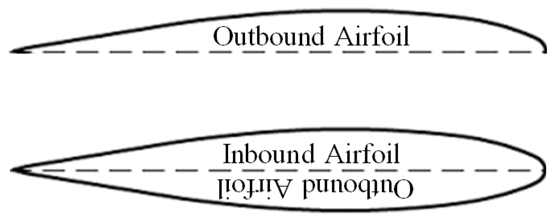
The morphing concept presented in this article relies on a hinged double segmented half span, which can be mechanically folded in such a manner that the outbound wing is tucked underneath the inbound wing (see Figure 1). The resulting airfoil of the folded plane is the combination of the inbound airfoil and the inverse outbound airfoil (see Figure 2). Thus an alternating transition occurs from a high aspect ratio aircraft with a fitting airfoil (which will be referred to as “glider” throughout this article) into a high velocity, improved manoeuvrability aircraft with a significantly shorter wing and a second, more favourable to high Reynolds airfoil (referred to as “aerobatic” throughout this article). note that both aircraft are motorized and the notation “glider” refers to the glider-like geometry of the wing.
The morphing concept enables the transition from the geometry of the “glider” into that of the “aerobatic” as described in Table 1.
The folding process has an effect on the design of the control surfaces located on the wing (i.e., flaps, ailerons, etc.). Thus, a simplification is assumed using elevons (which enables both elevator and aileron control) on the horizontal stabilizer.
The motivation of unfolding from the aerobatic configuration into the glider configuration is primarily rooted in endurance enhancement as will be described in through in the following section. The motivation of folding from the glider configuration into the aerobatic configuration is due to manoeuvrability improvement in (and not limited to) both pitch and roll manoeuvre allowing for the ability to perform a swift nose-down or tight roll.
First, an analysis is performed in order to assess the additional endurance gained by the morphing capabilities, compared to standard aircraft.
A suggested folding algorithm is outlined and certain aspects of the morphing process are highlighted, such as the roll stability during the morphing process and the required elevon necessary to maintain such stability.
Finally, an airfoil selection process is detailed and a wind tunnel test phase is described.

2.1. Endurance Improvement and Morphing Efficiency

The process of designing an aircraft for two distinct working points is quite complex, due to the fact that every parameter chosen for one working point greatly influence or even dictates the parameters of the second working point. The proposed aircraft concept consists of solely two singular points, folded and retracted, that might not be airworthy for the intermediate angles, beside the two extremes. This section shows the parametric study that aims at pinpointing a viable and economically desirable solution according to specific flight mission, that may serve as a design methodology for future conceptual designs.

2.1.1. Mission’s Scenario

The design process will initiate with the examination of the designated flight mission, which is a given input parameter. We will define χ as the over all portion of the flight mission that the aircraft is required to perform at low velocity (or at glider configuration). Every flight mission is contained within 0 χ 1 where χ = 1 represents a mission that relies solely on a low velocity and χ = 0 represents a mission that relies solely on a high velocity working point (or as the aerobatic configuration). Thus the portion of the flight mission that is performed at high velocity is 1 χ .
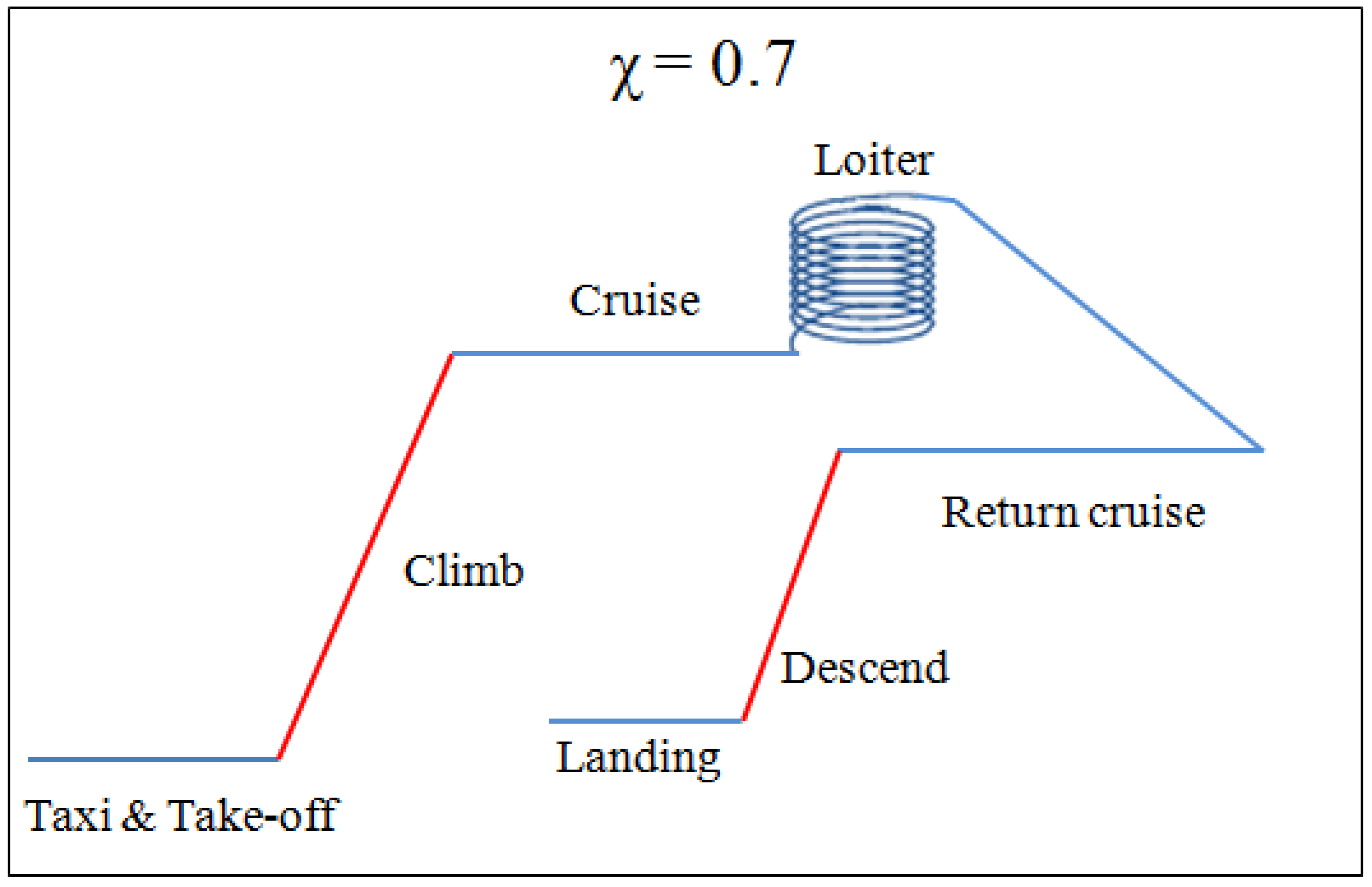
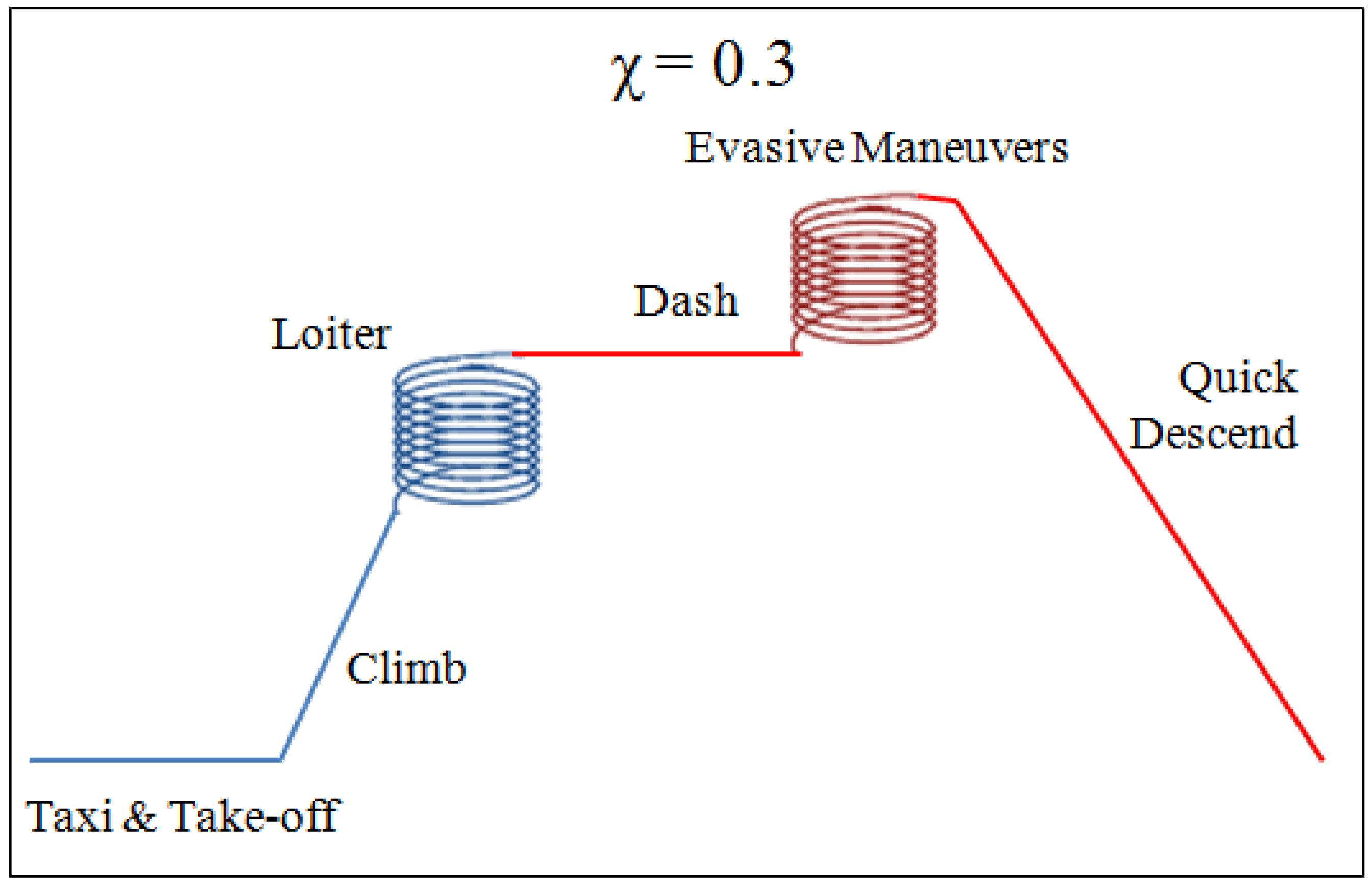
In this article, it was assumed that the required portions of the flight which are at low and high velocity (essentially defining χ ) are either given to the designer or a direct result of the flight mission requirements. However, it is possible that the designer may extract that data from standard flight mission profiles as exampled in Figure 3 and Figure 4. Those figures represent flight mission profiles and their corresponding χ . For simplification, the segments which are required to perform at low velocity and would later be suited for the glider configuration (e.g., due to high aspect ratio or increased wing area) are marked in blue, while the equivalent high velocity segments which would later be suited for the aerobatic configuration are marked in red.

2.1.2. Working Points and Morphing Efficiency

Let us consider two aircraft as portrayed in Figure 1 and Figure 2 with the summarized parameters listed in Table 1.
We shall assume that during the low velocity portion of the flight ( χ phases) the aircraft is maintaining a levelled flight, while during the high velocity and manoeuvring portion of the flight ( 1 χ phases), the aircraft is performing a manoeuvre, assumed to be equivalent to that of a steady climb. It is worth to note, that the manoeuvring phase may also be assumed to be a steady vertical or horizontal manoeuvre as well as any number of plausible representations. However, as a preliminary study that aims at asserting the viability of the morphing concept, this is a reasonable assumption. Thus the power required from the engine in the case of the first working point, (low velocity, levelled flight) is given by Equation (1):
P l e v e l l e d = D V
While the power required from the engine in the case of the second working point, (high velocity, steady climb) is given by Equation (2):
P m a n o e u v r e = D V + W V s i n γ
The overall power required to maintain a mission by any aircraft is given by Equation (3). When calculating the total power required to perform a mission by the glider configuration, we would use the denotion “ P g ” as well as “ P a ” when discussing the aerobatic configuration. In a similar fashion, “ P m o r p h i n g ” denotes the overall power required to maintain a flight using a morphing aircraft which alters geometry from glider to aerobatic at will.
P * = χ P l e v e l l e d + ( 1 χ ) P m a n o e u v r e
It is simple to show that the drag coefficient is given by Eqution (4):
C D = C f e S w e t A R b 2 + C L 2 π A R e = C f e S w e t A R b 2 + 2 W S ρ V 2 2 1 π A R e
The drag force is given by Equation (5):
D = 1 2 ρ V 2 b 2 A R C f e S w e t A R b 2 + 2 W S ρ V 2 2 1 π A R e
Using Equations (1) and (5), the Power vs. velocity of the glider can be calculated for any combination of wing loading and aspect ratio, given an assumption for ρ , C f e , A R e . Since the parameters the aerobatic configuration are defined using that of the glider, a second calculation can be made for that aircraft as well.
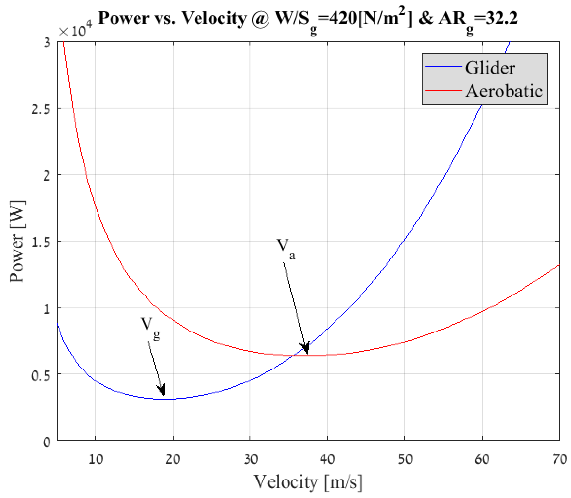
Figure 5 plots the Power due to drag vs. the velocity of the aircraft at specific wing loading and aspect ratio of both the glider and aerobatic configurations (The specific results are based on the assumption of ρ = 1.225 K g m 3 , A R e = 0.8 and the skin friction drag for the glider and aerobatic plane is C f e = 0.005 and C f e = 0.0055 respectively). The minimum point on each line represents the minimum required power which, in theory is the desired design point when striving for optimal endurance, noted “ V g ” and “ V a ”.
The conditions for maximum endurance are given by Equation (6) [16].
C D + = 4 C D 0 C L + = 3 C D 0 K V + = 2 W S ρ 3 C D 0 K
The endurance improvement is rooted in the ability of the morphing aircraft to “cherry pick” between the two configurations which yeilds lower power requirement at each velocity. However, since the morphing mechanism is bounded to correspond with additional weight, it is crucial that we quantify the advantages of such morphing aircraft over its fixed counterparts, so that we could compare the two against each other and make an educated decision. The added efficiency of the morphing concept over a standard A-like aircraft is defined by Equation (7), while the added efficiency of the morphing concept over the standard B-like aircraft is defined by Equation (8). Note that the added efficiency is defined as a percentage of improvement in the power requirement.
Ψ g = 100 · P g P m o r p h i n g P g
Ψ a = 100 · P a P m o r p h i n g P a
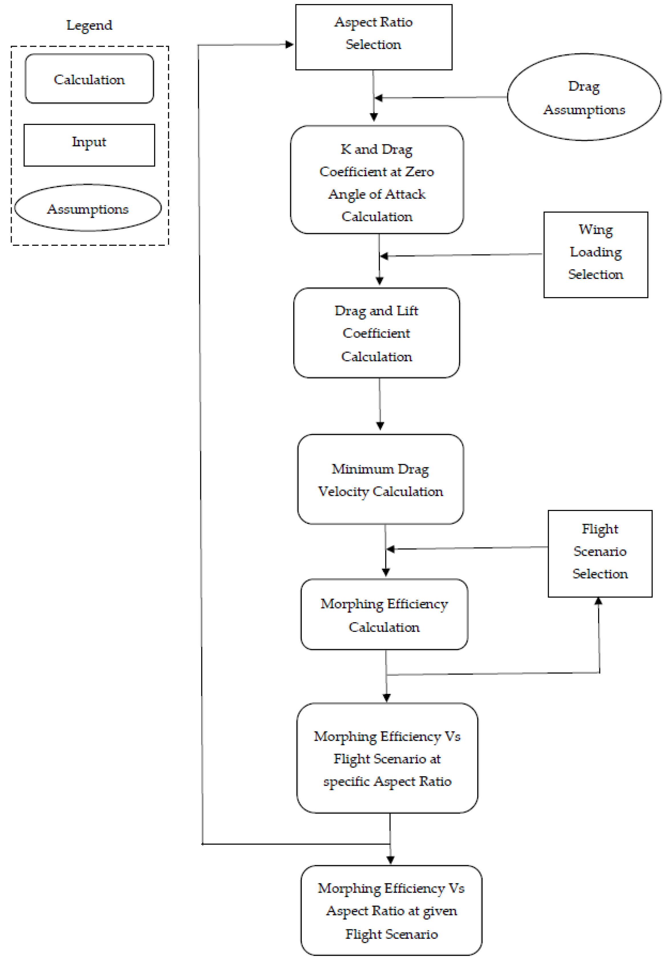
It can be inferred from the last paragraphs, that the morphing concept has the potential of contributing toward minimizing the flight power requirements. In order to realize this potential, we must quantify this contribution and compare it against the weight increase due to morphing mechanisms. The algorithm of the analysis used to determine the added efficiency of the morphing aircraft ( Ψ g , Ψ a ) is depicted schematically in Figure 6.
  • Aspect ratio selection—The initial input parameter for the analysis was chosen to be the aspect ratio. However, it was possible to launch the analysis with any number of valid parameters: wing area, χ and wing loading to name a few.
  • Drag assumptions—Skin friction coefficient ( C f e ) and Oswald efficiency number ( e ) were chosen from experience. Wetted area was also assumed to be a function of wing area and airfoil thickness so that S w e t = f ( S , t ) ; this assumption serves to simplify the drag calculation.
  • Drag calculation—A wing loading selection is made and using Equation (4) with the above input and assumptions yields drag data at specific wing loading and aspect ratio.
  • Minimum power velocity calculation—The lift coefficient and drag force are estimated. The velocity at which the power requirement is minimal is calculated for the glider configuration and accordingly, the minimum power requirement velocity of the aerobatic configuration is also computed.
  • Flight Scenario impact—A flight scenario is introduced into the analysis using χ and the morphing efficiency is calculated using Equations (7) and (8). In order to attain results at various wing loadings, an iteration loop is set from the drag calculation phase recalculating the efficiency at different wing loading values.
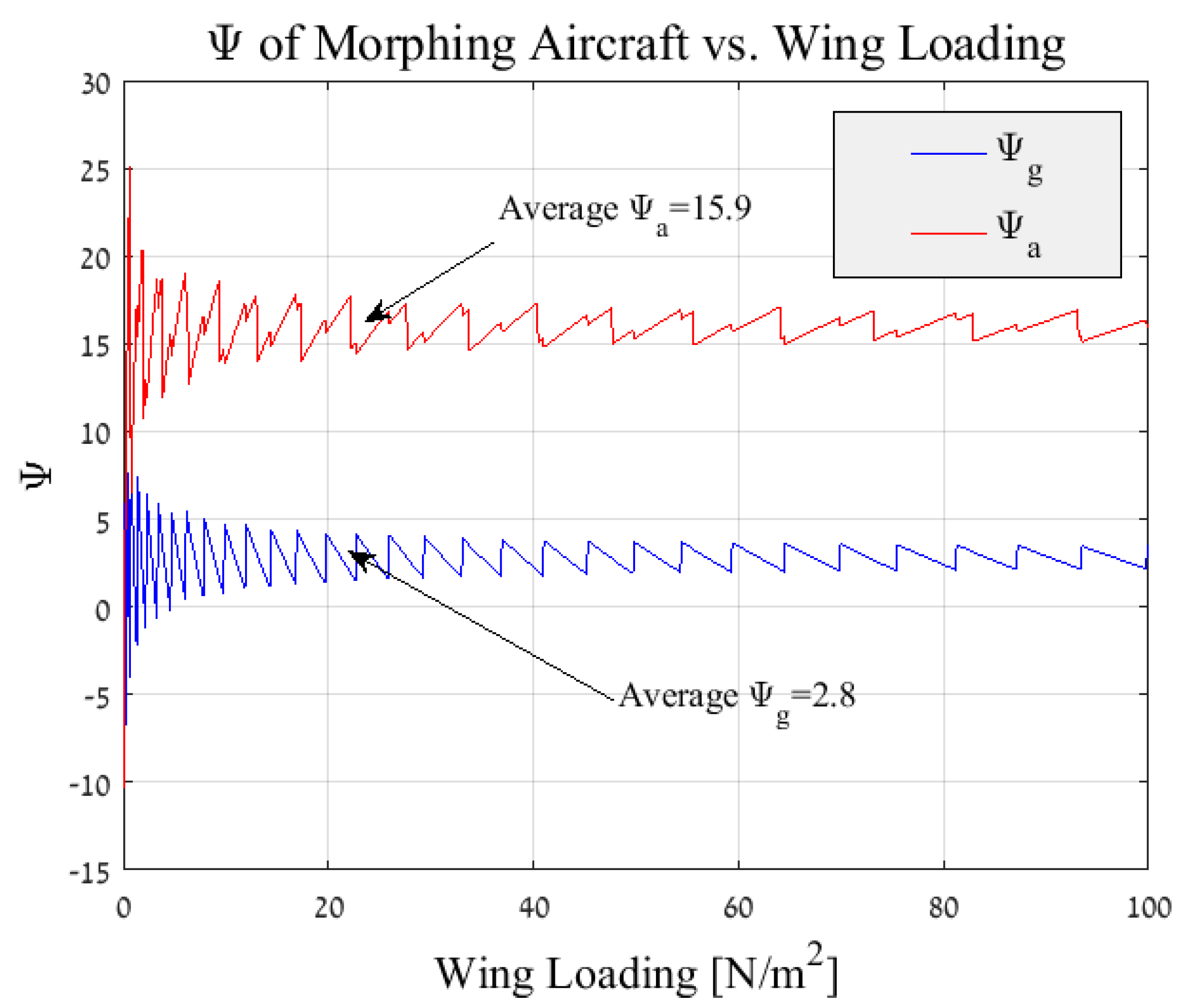
    Figure 7 depicts the morphing efficiency for a glider’s aspect ratio of A R g = 8 and a flight scenario of χ = 0.6 . It can be seen that the morphing efficiency is quite constant above a minimal wing loading. Thus for most applications, an average can be made and a single value of efficiency per aspect ratio and flight scenario is attained. This stagnation in efficiency is due to the affect of the wing loading on the minimum power velocity which serve as a control loop that maintains a steady value throughout the examined wing loading spectrum.
  • Final morphing efficiency calculation—Given a single value for the efficiency at every χ , an iteration loop is set from the aspect ratio selection (initial phase) and finally the calculating of the morphing efficiency at different flight scenario is obtained for a given spectrum of aspect ratios.
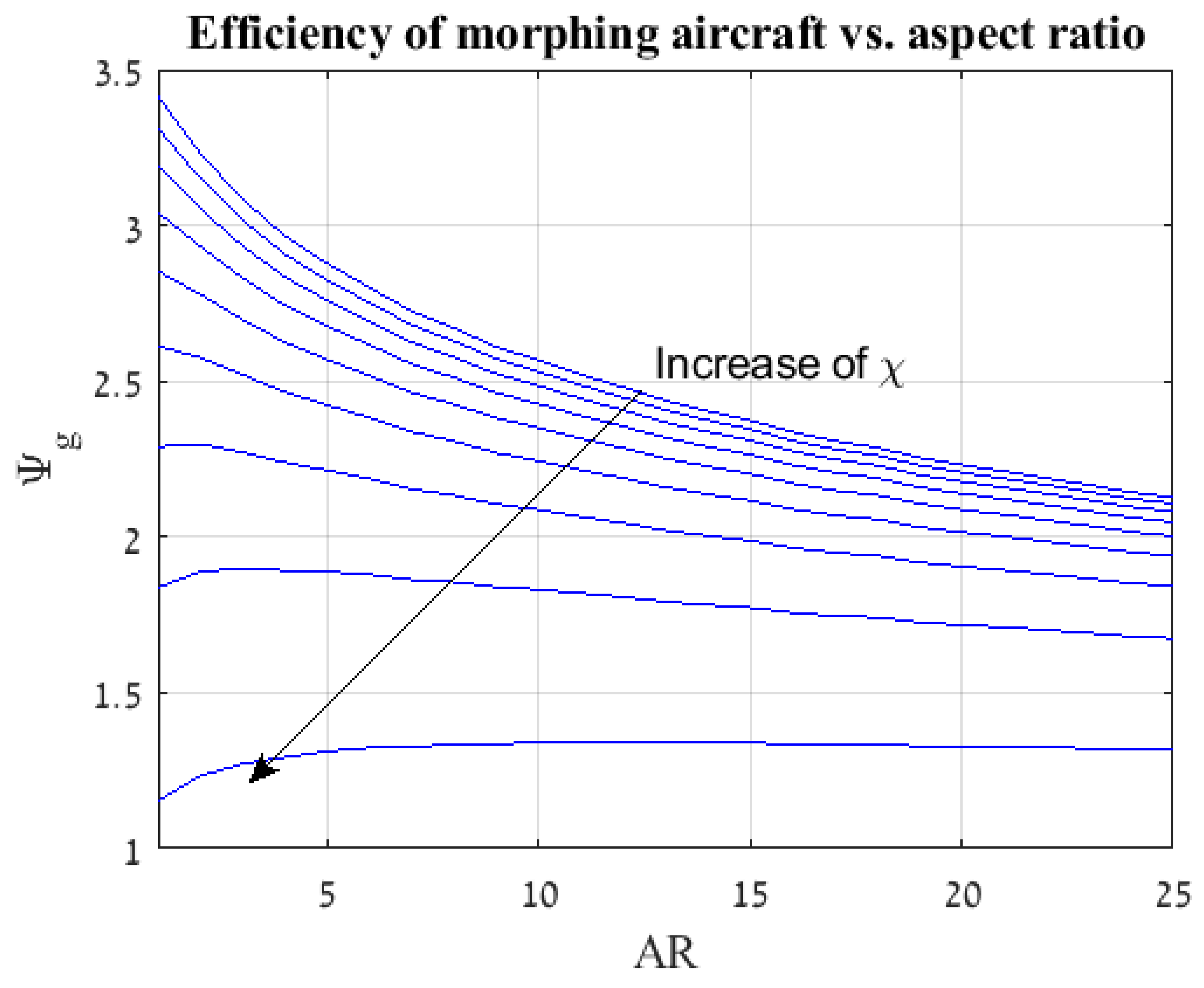
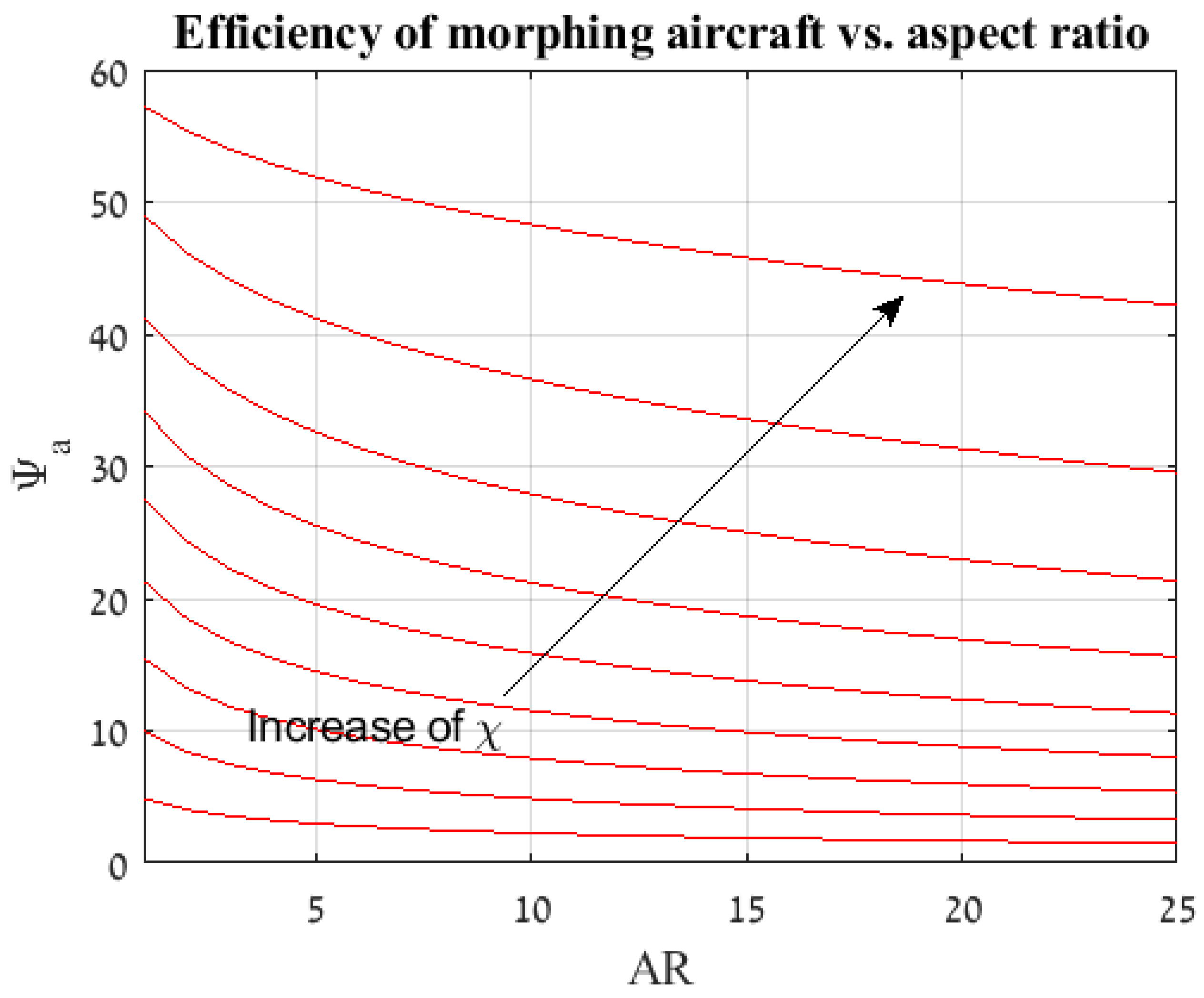
    Figure 8 and Figure 9 depict the results of the analysis for the morphing aircraft efficiency over the standard glider and aerobatic aircraft, respectively. Each line represents a specific χ and it is apparent that the flight scenario and aspect ratio are the main factors in determining the added value of the present morphing concept. As expected, for given flight scenarios that are defined with a larger value of χ (flight scenarios with increased phases of steady flight, such as loiter and others) the morphing efficiency or the “gain” from morphing over a standard glider is less prominent (see Figure 8). In a similar fashion, for flight scenarios that are defined with the same larger value of χ the morphing efficiency or the “gain” from morphing over aerobatic aircraft is increased (see Figure 9).
    Furthermore, it is visible that for this typical example the morphing efficiency Ψ a is significantly higher than Ψ g meaning that the power requirements are substantially lower for the morphing aircraft over its standard aerobatic counterpart. This is due to the behaviour of the power vs. velocity as is presented in Figure 5. During the flight phases where the standard aerobatic aircraft is required to maintain the glider’s velocity ( V g ) , the power is significantly increased, subsequently the overall efficiency is increased. However, during flight phases were the standard glider is required to maintain the aerobatic aircraft’s velocity ( V a ) , the power is indeed increased only not by the same magnitude leading to less “profit” for the morphing concept, yielding to a lower morphing efficiency.
    This is not a general conclusion and is bounded to the assumptions made during the analysis pertaining the drag and wetted surface functions.

2.1.3. Weight Consideration

The additional weight accumulated as a result of the morphing mechanism has an adverse effect on the morphing efficiency. Since the morphing aircraft is complicated and costly to design compared with a standard aircraft, a designer may view a severe negative effect on the morphing efficiency as a deterrent to the specific design. Thus, an analysis was performed in order to quantify the degradation in the morphing efficiency.
The analysis presented so far took into consideration the aircraft’s weight within the selection of the wing loading. The aircraft weight did not contain added weight due to morphing, meaning that the efficiencies calculated represented an ideal case.
Furthermore, it was shown that for a given aspect ratio the change in wing loading did not alter the morphing efficiency and the latter was subsequently averaged throughout the analysis.
The weight of the morphing mechanism was calculated as a percentage of the standard glider’s weight and noted d W m m , this figure, which includes all mechanisms and structural parts that were added in order to gain the ability to morph either directly or indirectly. Thus, the weight of the morphing aircraft can be represented as a function of the standard aircraft weight as presented by Equation (9).
W M = W ( 1 + d W m m )
The wing loading of the morphing aircraft can be presented in a similar fashion:
W M S = W S ( 1 + d W m m )
For each flight scenario χ , a morphing efficiency calculation was performed for a spectrum of aspect ratios in the same manner that was previously shown. The weight of the morphing mechanism was initially set as zero, and the minimum drag velocity for the ideal case was calculated. The analysis was then repeated for a variety of morphing mechanism weights, however the velocity at which the original aircraft is most favourable was unaltered in order to compare between the configurations. Figure 10 and Figure 11 present the result of the analysis given the same assumptions used in the analysis presented in Section 2.1.
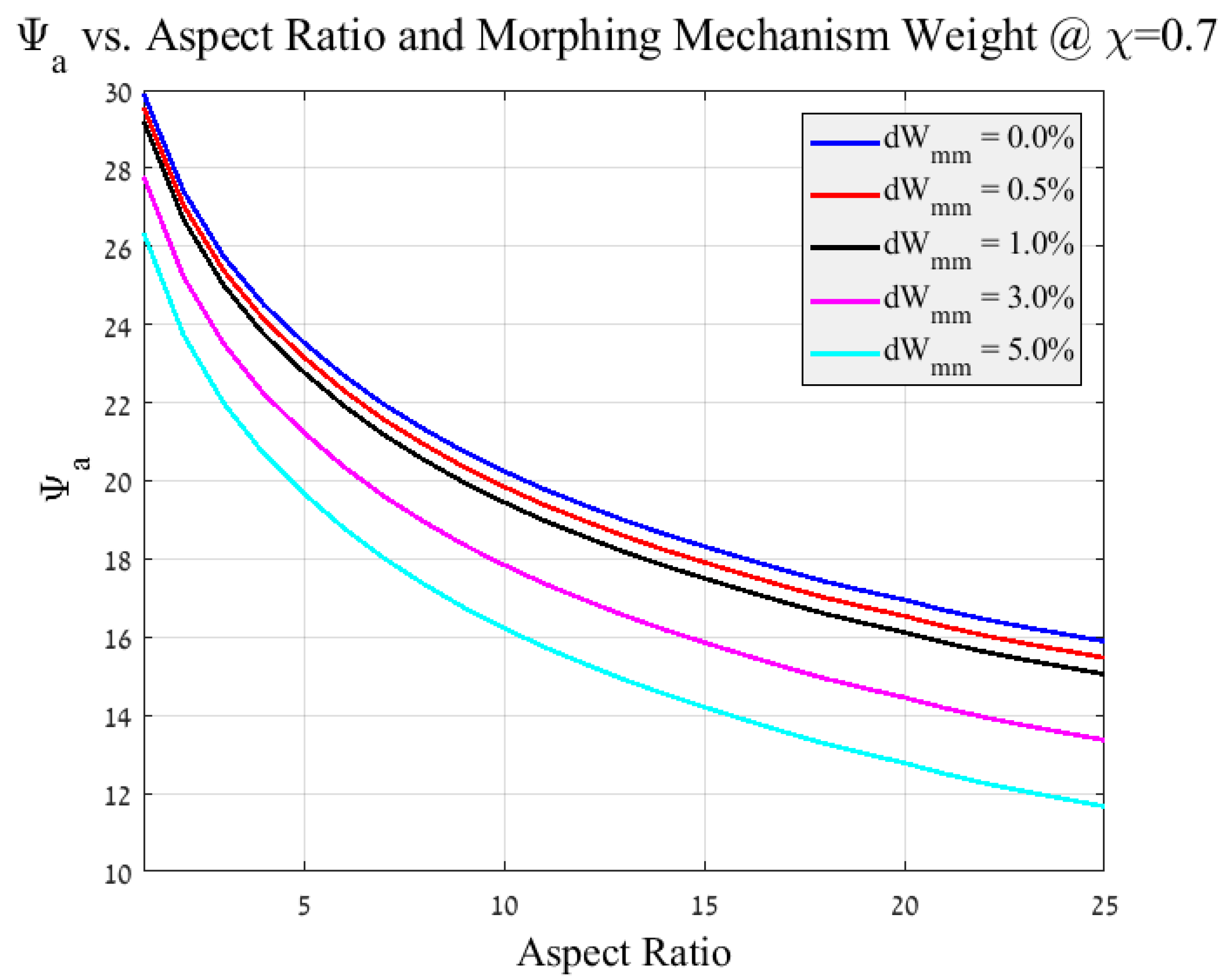
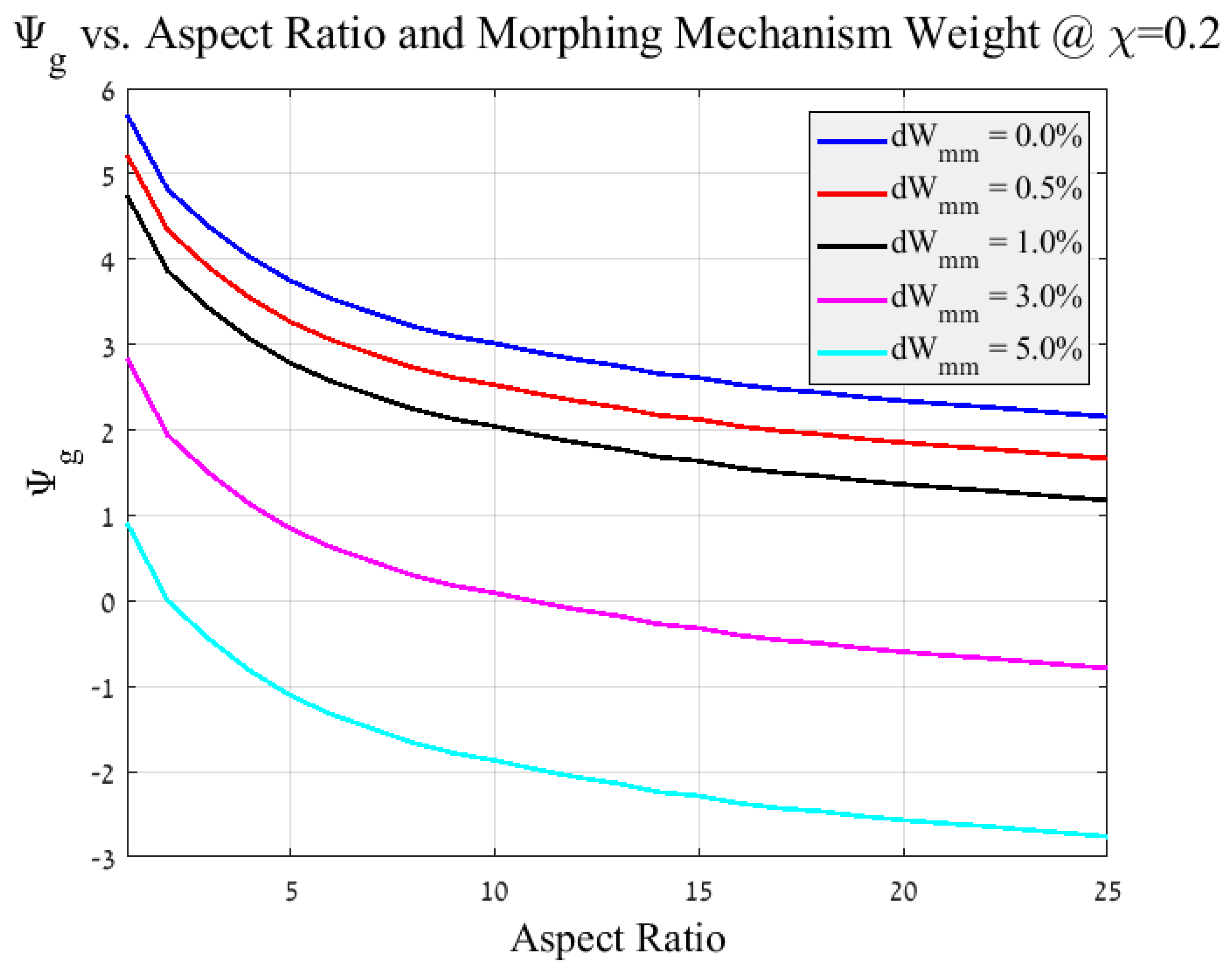
As expected, the weight of the mechanism has a significant effect on the morphing efficiency, a five percent increase is translated into a reduction of approximetly 20% in the aerobatic morphing efficiency (see Figure 10). The decrease in efficiency progresses with additional mechanism weight and at a certain value of d W m m will present a negative efficiency as shown in Figure 11 resulting in a specific design that would have shorter endurance compared with a glider that performs the original flight scenario without morphing.
The task of defining the morphing mechanism weight is not a straight forward one, albeit certain mechanisms such as motors or wiring can be pin pointed to the morphing concept, however, structural components such as flexible skin, spars or folding ribs perform tasks which are mutual to both the morphing and standard structural design. In these cases the prospective designer will need to asses the weight of a standard structure as well as that of the morphing one in order to identify the increment. This means that the prospective designer may need to perform a conceptual design for the glider and aerobatic aircraft prior to designing the morphing one. However this is a somewhat intuitive preluding phase of the morphing conceptual design.
In the presented results, the morphing efficiency’s decrease is significant while still maintaining a sizeable improvement compared to the aerobatic standard aircraft (see Figure 10). Therefore the designer would need to choose an efficiency above which the morphing is favourable over the standard counterparts.
Furthermore, Figure 10 and Figure 11 depict maximum additional weight of 5% of the overall aircraft weight. However, Additional study is needed to ratify the validity of this assumption.

2.2. Morphing Algorithm

During the transition from one working point to the other, the wing span, aspect ratio and lift surfaces are substantially altered. Additionally, the direction of the lift vector in the outbound surfaces undergo a 180 change during the folding or unfolding process.
Given a purely symmetrical folding phase, the horizontal component of the lift vectors from the two outbound wing section work to negate each other and we are left to deal with the change in the vertical components.
Throughout the folding process, the overall lift of the aircraft is reduced with correlation to the magnitude of the folding. Theoretically, given an angle of attack of α = 0 and equal outbound and inbound lift surfaces, the lift at the point of completed folding phase is L = 0 due to the nature of symmetric airfoils at α = 0 .
Thus, if lift is desired at the end of the folding process, a positive angle of attack must be maintained during the process. Alternatively, a non-symmetric airfoil may be chosen for the folding configuration. However, this option carries a complication penalty described in detail in Section 2.3. A third option may include the usage of a smaller outbound wing surface compared to the inbound surface, in a manner that would serve to maintain some effective lift surface post folding. albeit effective, this approach reduces the overall level of morphing and thus can be considered as counter-efficient.
Furthermore, reality dictates that the transition will not be completely symmetric as presumed earlier. Hence, a roll moment (as well as a yaw moment) may be introduced due to differences in the horizontal component of the lift vector in both of the outbound sections. Consequently, a correction is required using the elevons at the tail. It is possible to achieve the same roll control using ailerons/air-brakes at the inbound (static) portion of the wing, as well as to use ailerons at the outbound section of the wing. However, the latter necessitates a complicated control algorithm and both of the aileron-based solutions would present a mechanical complexity to the already challenging wing design.
The roll moment due to asymmetry, the ability to control said roll as well as the lift change from one configuration to the next are all affected by the velocity of flight. While it is intuitive that the folding (or unfolding) will take place at either V g or V a (the velocity of the previous state or the velocity of the following state), it is possible that prior to transition, the velocity will be set to a separate value that would allow for efficient transition accompanied by an increase or decrease to either V g or V a .
One plausible solution may be to reduce the velocity below V s t a l l and thus reduce the effect of asymmetry and lift change. Theoretically speaking, at V = 0 m s the issue is eliminated altogether with the drawback of losing the use of the control surfaces and overall lift during that period of time. This may be acceptable for a UAV, given a relatively swift transition and sufficient altitude.
Given the complications listed above, it is imperative that the transition phase is done swiftly and with a high level of symmetry. Figure 12 depicts the proposed overall transition algorithm.
It is visible in Figure 12 that the folding and unfolding is preceded and succeeded by an unlocking and a locking phase. A locking mechanism is necessary in order to maintain the two end geometries, regardless of the aircraft’s position and forces that act upon it. This locking mechanism can be implemented within the transition mechanism as is presented in most control surfaces, such a constant hydraulic pressure or continuous power supply to a motor as in the case of electric servo controlled surfaces. However, the high level of modification introduced to the structure in this case, means that vast forces are required to maintain the end positions (as high as one half of the overall lift of the wing), as opposed to most moving mechanisms in the aircraft.
The transition (or morphing) phase is dissimilar when discussing folding compared to unfolding. A mechanism designed to fold must counter the lift of the outbound surface in order to create movement, the same forces during the opposite process will assist the mechanism and the lift may cause the surfaces to unfold on their own. In this case it is possible that the mechanism will only have to control the timing of the transition so that the symmetry is maintained.
A possible solution is to perform the folding phase at low velocity, such that the counting forces on the mechanism are negligible, while the unfolding phase is done at high velocity so that the wing attempts to unfold itself. This would allow for a relatively swift morphing for a low-powered morphing mechanism.

Roll Stability during the Morphing Process

As stated in the previous paragraph, it is quite probable that the folding process will not be completely symmetrical, hence a roll moment is expected. In order to keep the proposed morphing concept feasible, an analysis was performed to ensure that the aircraft is capable of performing a roll-wise stable folding manoeuvre.
First, the extreme case scenario must be defined. The folding process can be discussed as the forming of an Anhedral at the half span of each wing, noted by the angle Γ . As the folding process proceeds, the anhedral is increased until a complete folded state is achieved, thus the anhedral angle is of the range of 0 < Γ < 180 .
The roll moment around the center of gravity of a single half wing (inbound and outbound section) is given by Equation (11). For the sake of simplicity, the center of gravity is assumed to be located in mid-span of the wing. Furthermore, the roll moment due to the lift generated by the static inbound wing section was omitted since it would cancel when the second half of the wing is factored in.
L A n h e d r a l = L cos Γ · b 4 + b 8 cos Γ + L sin Γ · b 8 sin Γ
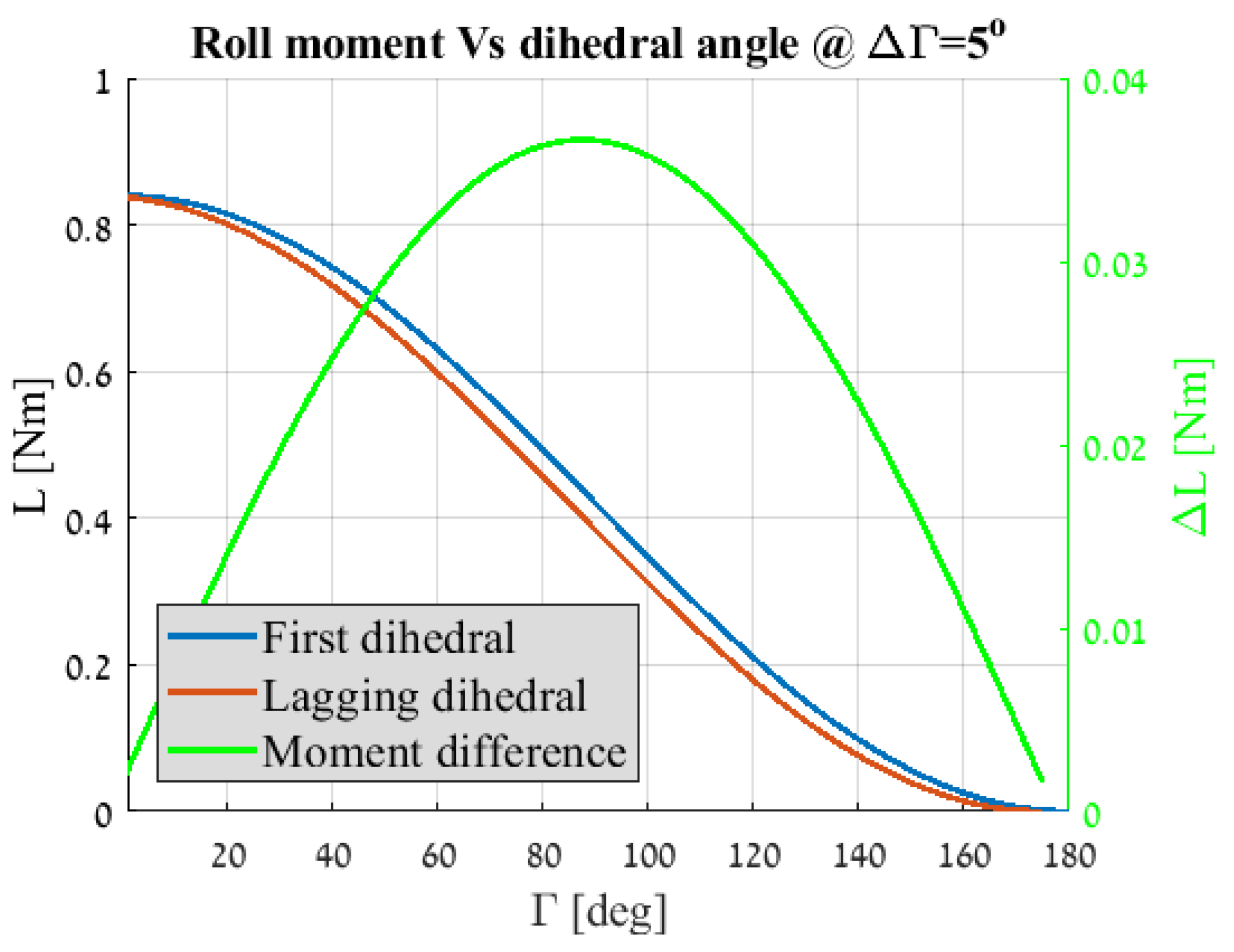
The roll moment was calculated for a complete folding process of one half wing. An assumption is made as to a difference in the anhedral angle of the second folding wing, such as that it is lagging by a Δ Γ after the first anhedral. Figure 13 depicts the roll moment at the center of gravity for both anhedrals, as calculated for a UAV with a wingspan of b = 2 m, a weight of W = 8 kg and a lift coefficient of C L = 0.7 .
It can be inferred from Figure 13 that the maximum difference in the roll moment is given for Γ 90 , meaning that the most extreme scenario is when the first folding segment reaches the point of a half fold (outbound wing segment is pointing downwards). However, this result is plotted for the specific case of Δ Γ = 5 , the conclusion as to the position of the wing segments at extreme roll moment would differ when the lag is increased. The anhedral angle of maximum roll is decreased with the increase of the lag between the two wings. In the present study, the actual moment difference between the two wings is used for further calculations. Nonetheless, for an anhedral lag of Δ Γ < 15 , it is a fair assumption to define the maximum roll moment position as the downwards facing position of the outbound wing section ( Γ = 90 ).
In order to sustain a steady flight, the roll moment caused by the lag in the folding wings needs to be reconciled by the elevons, the equilibrium is expressed in Equation (12).
L A n h e d r a l 1 s t L A n h e d r a l l a g = 1 2 ρ V 2 S H b H C L δ a · δ a
Substituting Equation (11) into Equation (12) yields:
b 8 L 2 cos Γ 1 s t + 1 b 8 L 2 cos Γ l a g + 1 = 1 2 ρ V 2 S H b H C L δ a · δ a
Equation (13) can be further simplified and the required deflection angle of the elevon is calculated as a function of the aircraft geometry and the wings anhedral angles as given in Equation (14).
δ a = 1 4 b b H S S H C L C L δ a cos Γ 1 s t cos Γ l a g
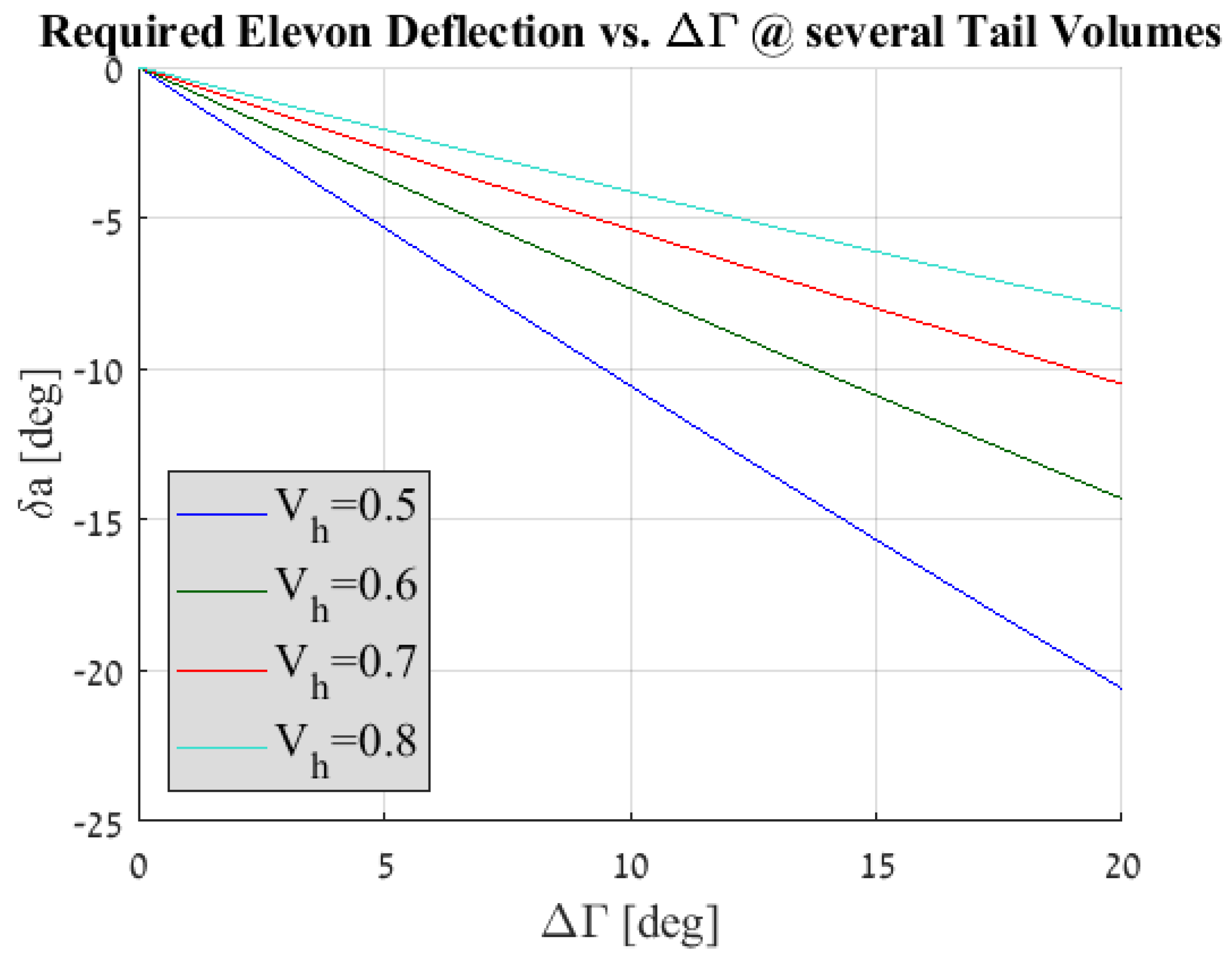
An assumption was made as to the wing to horizontal tail span ratio and area ratio as well as an assumption regarding the airfoil selection for the two surfaces. Figure 14 depicts the required elevon deflection angle versus a range of anhedral lags, assuming that the first wing segment is position at the maximum roll angle. The calculation was repeated for several horizontal tail volumes.
It can be deduced from Figure 14 that for a conservative horizontal tail volume of a glider V H = 0.5 , the required elevon angle is quite reasonable for a wide range of Δ Γ . This means that a roll-wise stable flight is possible. Moreover, the trade-off between the quality of the mechanical solution which limits the lag and the horizontal tail volume can be achieved and factored in for future design.

2.3. Airfoil Selection

2.3.1. Dominant Aerobatic Aircraft Working Point

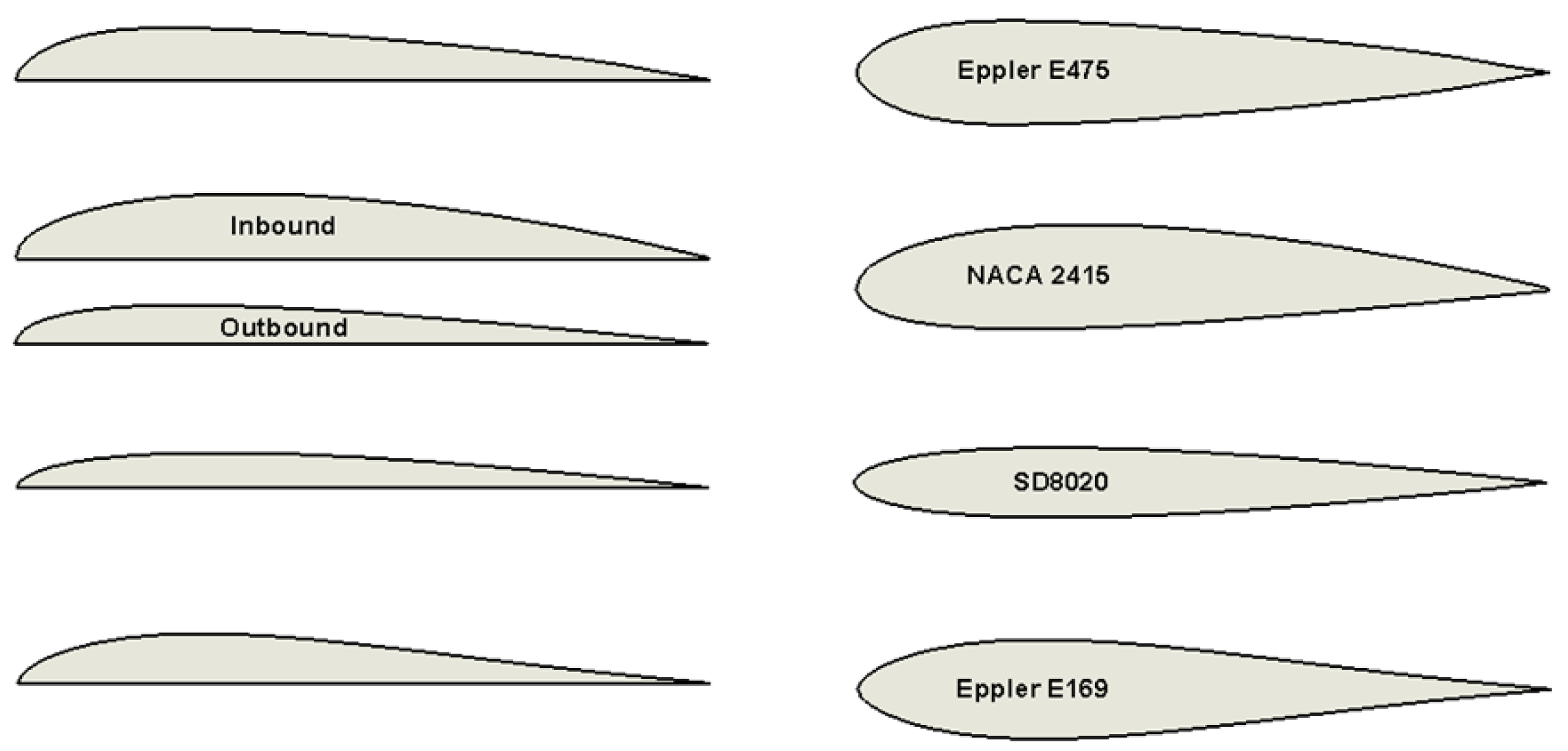
If we were to designate the aerobatic aircraft as the dominant or the “original”, upon retraction, a knifed edge of some sort would be generated in the leading edge of the glider as portrayed in Figure 15. The figure presents several airfoils that were considered for high velocity working point and the result of unfolding them.
For purely symmetric airfoils (i.e., Eppler 475), the resulting unfolding airfoil is identical along the entire unfolded surface of the wing and is an exact geometrical half of the retracted airfoil. However, for the other cases, the result would be a dissimilar airfoil for the inbound (or ’static’) wing surface and the outbound (or ’retractable’) wing surface (i.e., NACA 2415). This attribute might be used towards an improvement of the aerodynamic properties of the wing however, this would not be easy to design.
The sharp-edged airfoils stand in contrast to ’traditional’ smooth and round leading edge concepts and as such is quite unintutive.

2.3.2. Dominant Glider Working Point

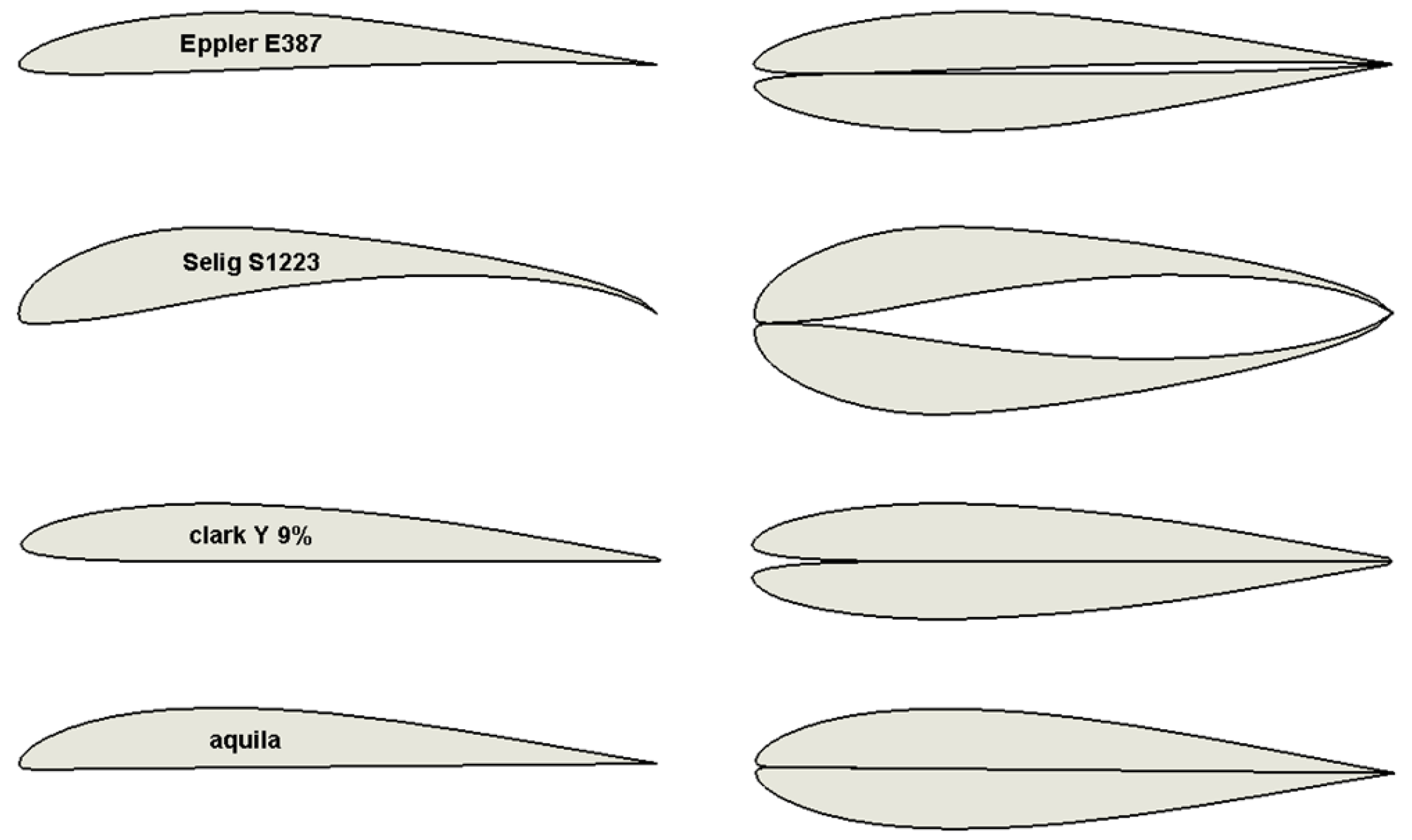
If a glider configuration is defined as the dominant working point, upon folding a gap would appear at the leading edge of the aerobatic configuration. Figure 16 illustrates several of the considered ideas. One should also note that concepts where the fixed and folding surfaces contain dissimilar airfoils are not presented. However, the following discussion can shed light to those concepts as well.
The chord-wise length of the gap, which is a defining character of the original airfoil was denoted by Δ and presented in percentage of the chord. For example the value Δ = 10.8 implies a gap that is protruding into the front 10.8% of the aerobatic airfoil.
Initial attempts to analyse these airfoils using standard airfoil analysis codes were deemed to be futile, as the gap produce, either non-convergence or outrageous aerodynamic characteristics. Common sense would dictate that the gap would have some adverse effect on the aerodynamic qualities of the airfoil in comparison to that of a standard leading edge. Two methods of improving the gaped airfoil were suggested:
  • Surface panel
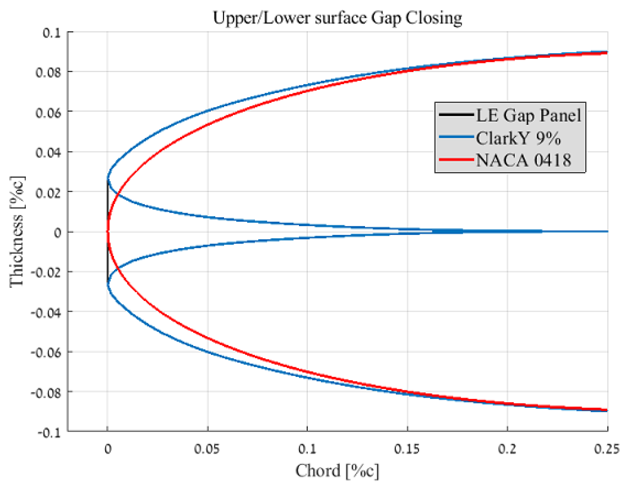
    In this concept a single panel on the lower or upper surface of the wing would retract and pushed forward in a manner that would eliminate the gap. This concept can be realized by either two methods, either two panels from both the static and folding wings are used to close the gap, or a single panel originated from the static wing would solely perform the gap closing action. The latter method serves to reduce mechanism weight at the wing tips. The surface concept, if implemented, would result in a new airfoil, in which the leading edge gap is sealed from the airflow and can be visualized (in the most general way) as an airfoil with a single panel that connects the forward most points of the upper and lower surface (see Figure 17). Several airfoils were compared to an equivalent NACA 4 digit approximation airfoil. This was done in order to evaluate the adverse effect of the leading edge gap. This comparison might be considered fair, since the NACA 4 series airfoils represent improvements to the shape of the leading edge with minimal effect to the remainder of the chord-wise geometry of the airfoil and thus can alleviate some analysis complications for an early stage design.
    The closing of the leading edge via a NACA 4 digit approximation is valid for preliminary design and is likely to give good indication for either the mechanically closed gap as well as the original opened gap airfoil. As for the deeper gaped airfoils, the approximation is not as productive. It poorly predicts the mechanically closed gap and is further intuitive that these approximations will not correlate with the opened gap airfoil.
  • Thickness reduction
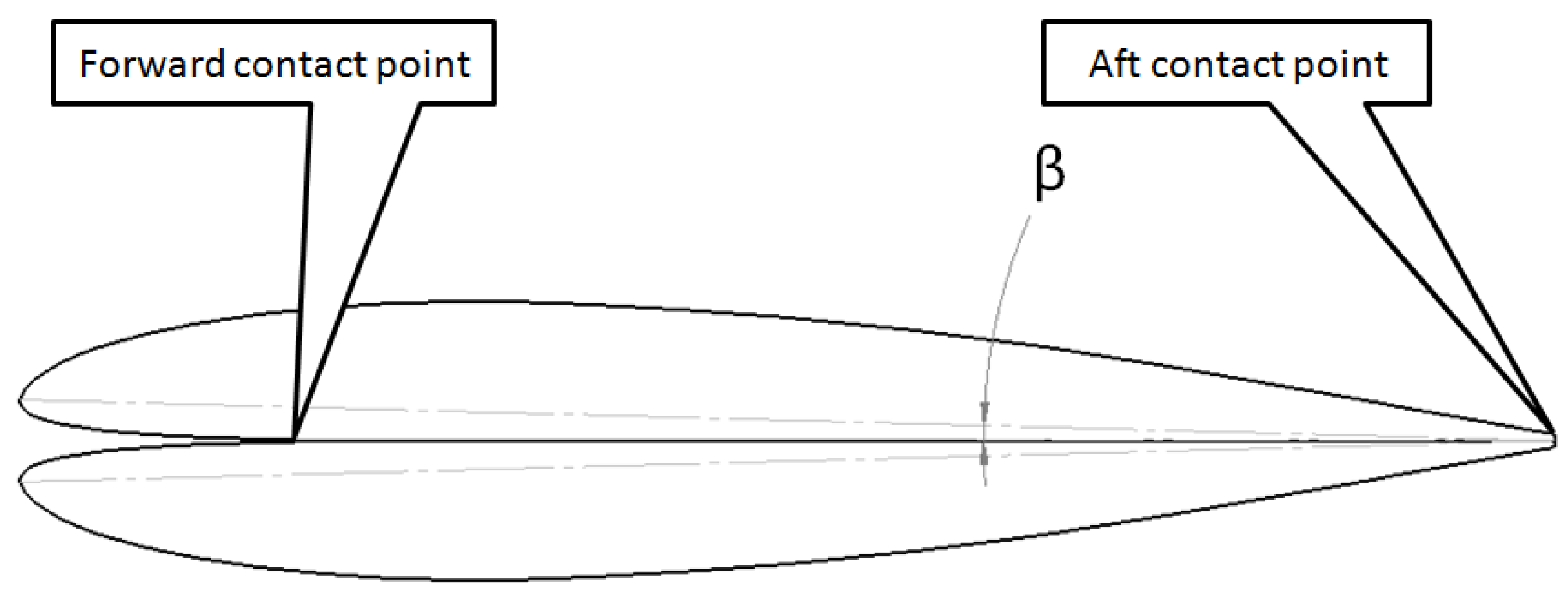
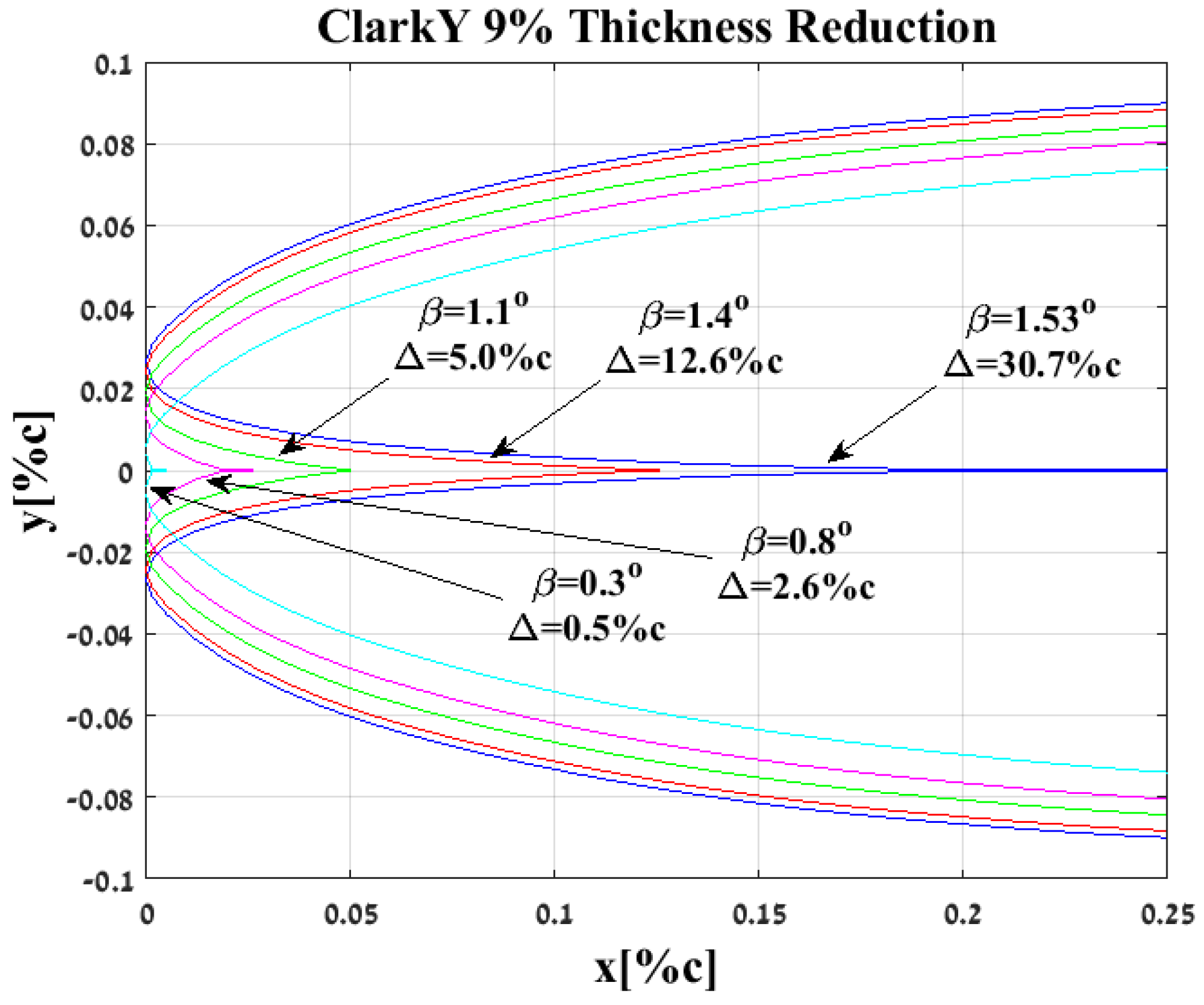
    Thickness reduction is an amending concept which eliminates the gap entirely by means of allowing the two wing sections to contract along their lower surface toward one another. This would be achieved by a flexible skin at the front lower surface which allows that two wing sections to merge into a more slick gap-less airfoil. The contracting form used for this procedure is based on two contact points between the two lower surfaces of the mirrored airfoil. An aft contact point at the trailing edge and a forward contact point at the origin of the gap (see Figure 18).
    Let us denote the angle of retraction as the angle between the chord line and the symmetry plane of the two airfoils with the symbol β (see Figure 18), so that the angle between the two chord lines of the airfoils is 2 β .
    The gap can also be expressed as a function of the distance between the symmetry plane and the leading edge, noted y L E . Reduction in β diminishes the leading edge distance to the symmetry plane until y L E = 0 , meaning that the gap is eliminated. The correlation between the two is presented in Equation (15).
    β = t a n 1 y L E c
    An investigation of the resulting parameters of thickness reduction method was performed; the airfoil used was an initially long-gaped airfoil, the outcome of a ClarkY 9% folding, possessing a 30.7%c gap prior to reduction. Figure 19 provides a visual representation of the assimilation of the two airfoils.
    At β = 0 the gap is no more and the ’new’ airfoil can be assessed via conventional analysis tools which were unavailable up to this point.

2.4. Wind Tunnel Models and Testing

The addition of a leading edge gap to the examined airfoils resulted in non convergence of traditional airfoil analysis tools (this is true for even a minute gap). Thus a more empirical method was used to determine the aerodynamic properties of the unique airfoil.
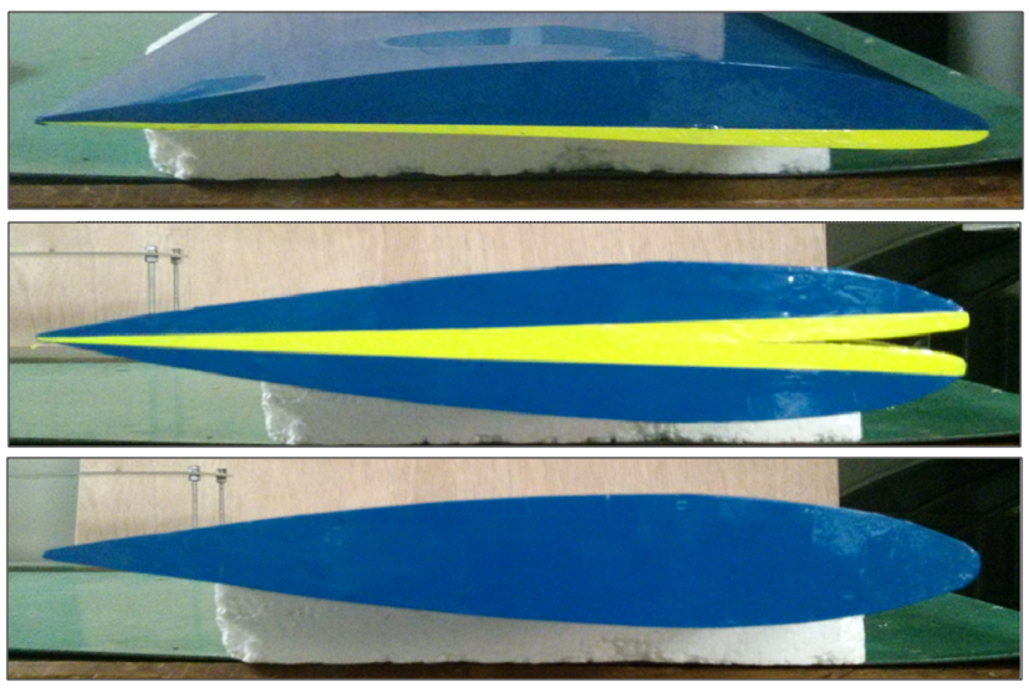
Four wing sections were built to provide adequate answers for various queries raised during the present article. The set of sections assumed that the dominant working point is that of a glider transforming at will via folding to an aerobatic aircraft. The airfoil used for the low velocity is that of ClarkY 9% due to a substantial leading edge gap that is produced after folding (see Figure 16), which might aggravate any phenomena related to the gap. The first section was that of an unaltered ClarkY 9% which serves as a control point for further reference and comparison (see Figure 20).
The second section was that of a completely folded form, meaning a ClarkY 9% on top of the other forming a 30.7% leading edge gap (see Figure 20). This section was noted “G2A30.7” for being the end result of a Glider-like aircraft to Aerobatic-like aircraft transformation, resulting in a 30.7 percent chord leading edge gap. In order to accurately mimic the geometry of a folded airfoil, this section was actually built as two separate ClarkY 9% sections that were combined together at later phases of the building process.
While the first two sections served as the fixed folded or unfolded airfoils, the two remaining sections were used to ascertain airfoil improving techniques discussed earlier.
Section three was used to examine the attribute of thickness reduction method. The β angle between two the airfoils of a folded configuration was decreased until the leading edge gap was zero ( Δ = 0 ). This airfoil was denoted “G2A0.0”.
The fourth and last section was used to examine the attribute of surface panel method. This was achieved by using the second section (G2A30.7) for a second test while closing the leading edge gap in a mechanical manner using a smooth rigid tape.
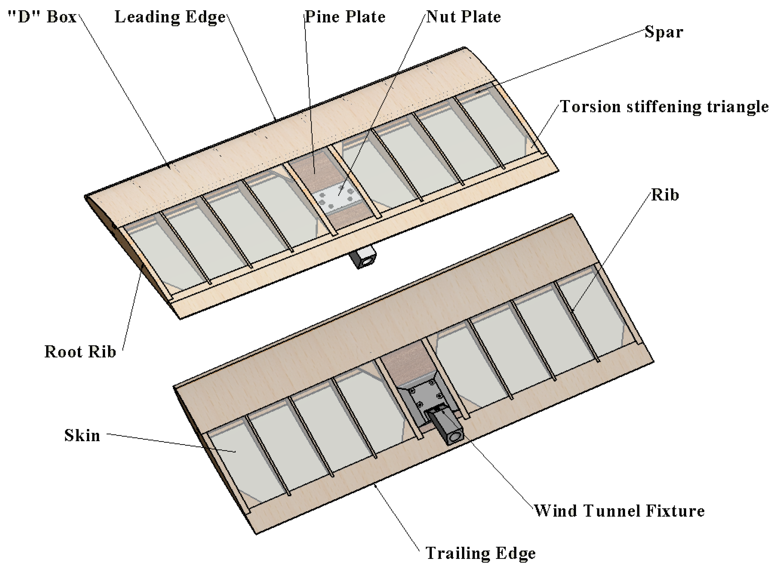
The test models were built as a “realistic” wing section with a wingspan of 0.6 m and a chord of 0.25 m , using a D box leading edge and spars configuration as well as balsa ribs enclosed in a polyester film. For visual purposes the upper surface of the ClarkY 9% was coloured blue while the lower surface was coloured in yellow. The sections were fixed during the wind tunnel tests using a steel fixture place at the aft lower surface of each section (see Figure 21).
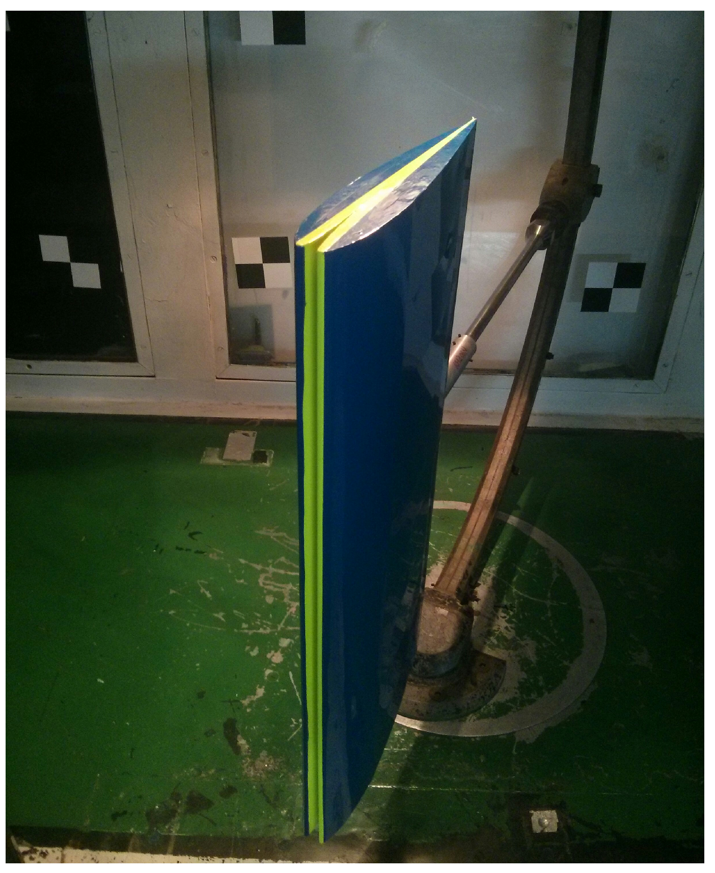
The four models described above were tested in the subsonic wind tunnel at the Faculty of Aerospace Engineering, Technion, I.I.T. on September of 2016. Each model was tested at velocities ranging from 10 m s to 30 m s , corresponding with Reynolds numbers of 1.6 × 10 5 to 5.0 × 10 5 and at angle of attack ranging from 25 to 28 (see Figure 22).

3. Results and Discussion

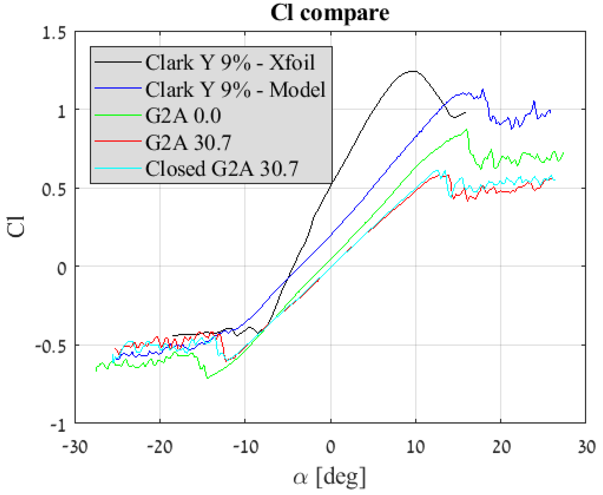
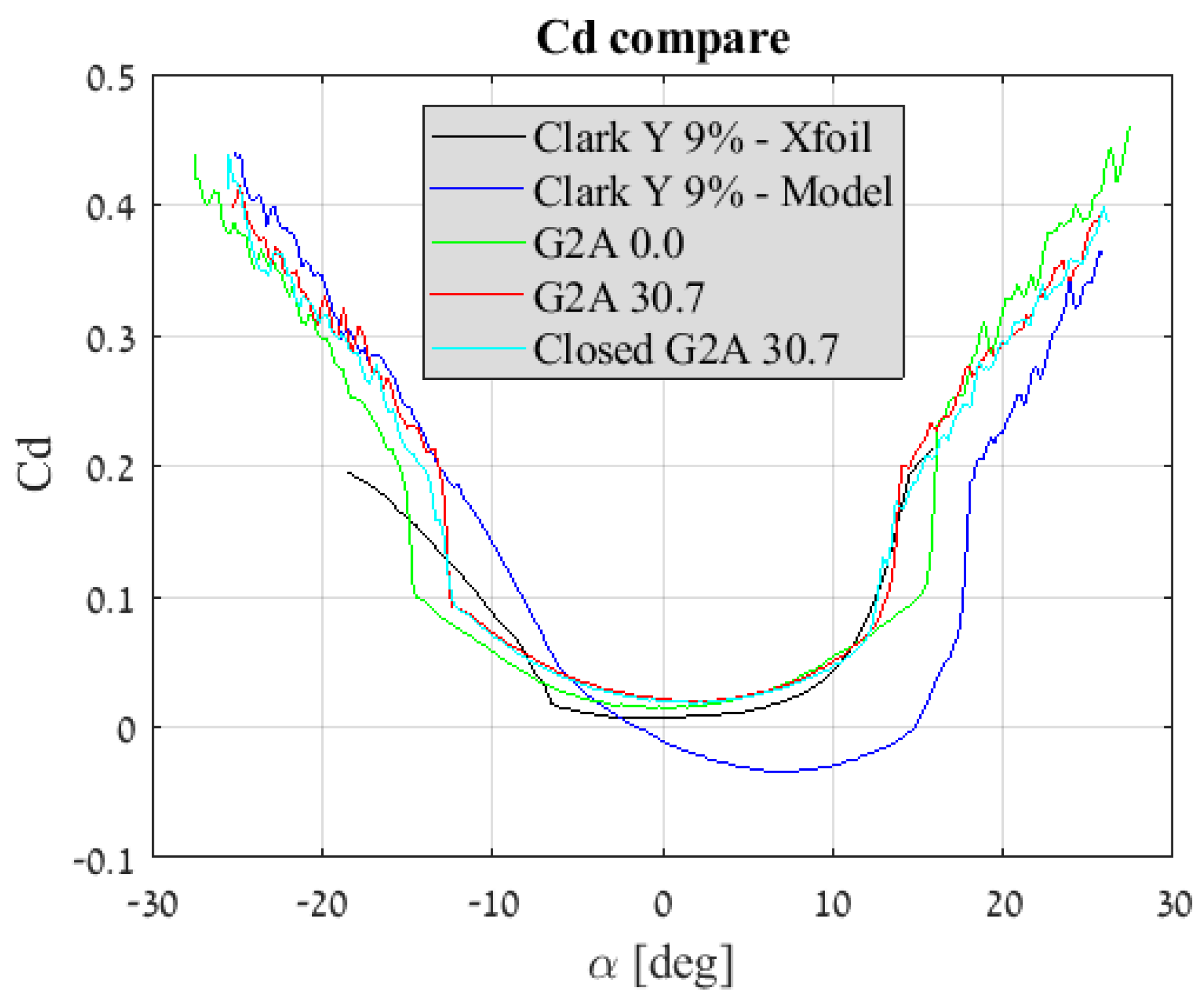
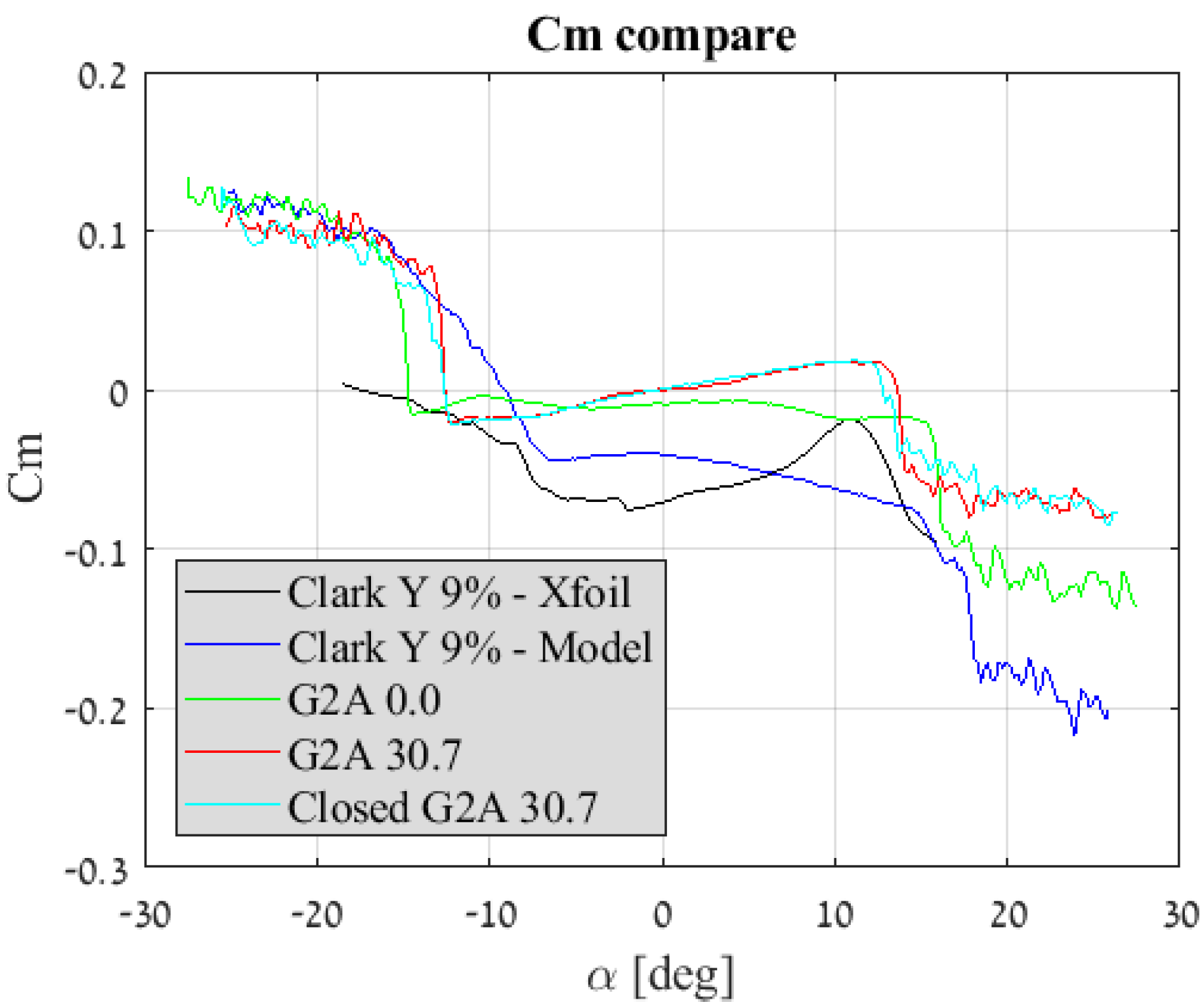
Figure 23, Figure 24 and Figure 25 presents the lift, drag and pitch moment (respectively) coefficient vs. the angle of attack for the four airfoil models tested at V = 20 m s . The figures also depict results of the a Clark Y 9% as calculated using Xfoil [17]. In addition, Table 2 summarize the main aerodynamic parameters obtained using the wind tunnel experiments.
It can be seen from the graphs that the glider’s airfoil (ClarkY 9%-Model) has a superior lift to drag ratio and is overall favourable compared to the other three airfoils. The other three models are all symmetric, yilding zero lift at α = 0 and a symmetric behaviour of the drag coefficient vs. the angle of attack.
Upon folding into G2A30.7 configuration, the maximum lift coefficient is reduced as well as the maximum angle of attack (at which maximum lift occurs). The drag is adversely affected as expected while the pitching moment coefficient is reduced, thus the folded configuration is less stable and more readily allows the “nose-down” manoeuvre as described earlier.
The difference in the results calculated by the analysis and those received by the wind tunnel tests can be explained by the effect of a finite wing in the case of the wind tunnel test model, as well as manufacturing inaccuracies of the handmade test models.
Attempting to improve the folded G2A30.7 airfoil by closing it with a front panel, had minimal effect on the aerodynamic coefficients. It was suggested that the lack of improvement in the aerodynamic coefficients is possibly due to the airflow creating a stagnation region at the gap’s vicinity and thus effectively “closing” the gap in G2A30.7 model, in much the same manner that was used in the wind tunnel test using a closed model via a straight vertical panel.
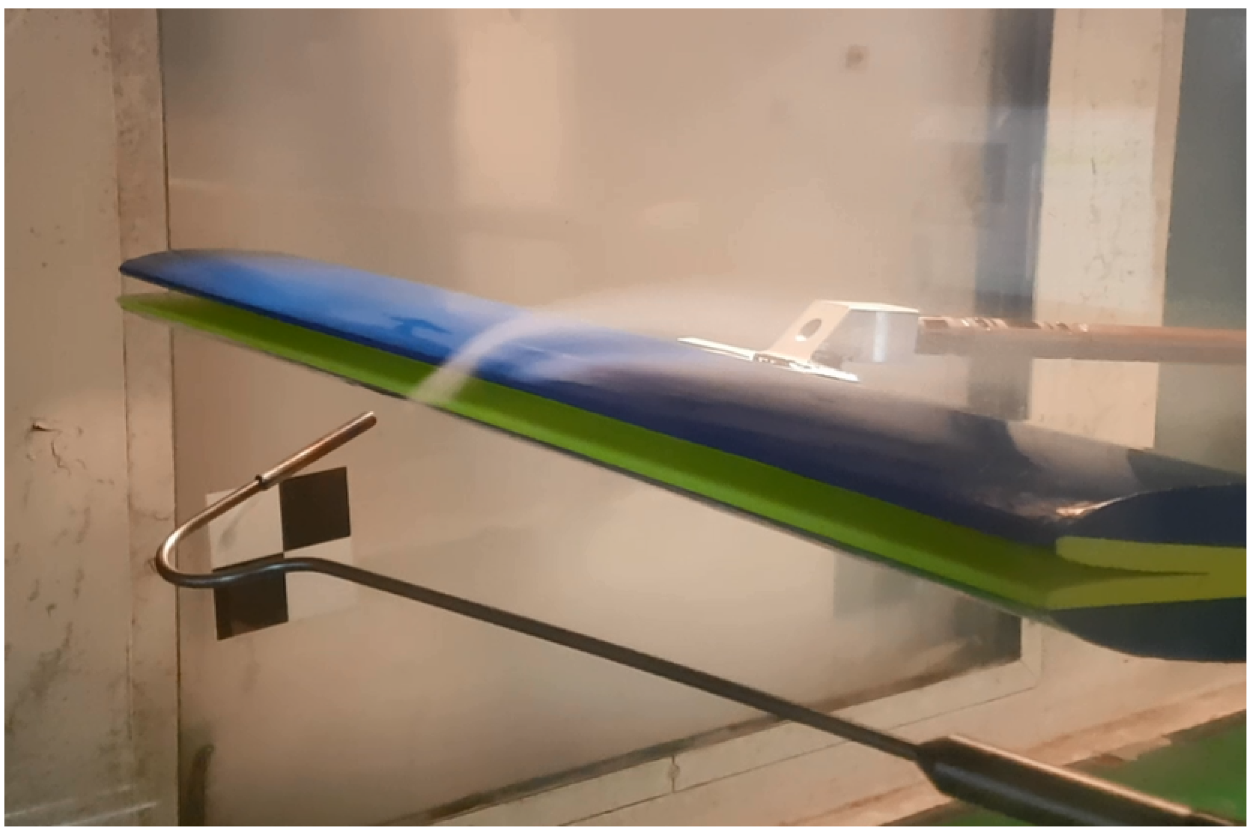
A second set of wind tunnel tests was held using smoke as a visual aid in order to assess the validity of the above assumption. Figure 26 depicts the smoke test results on the G2A30.7 model. It was discernible that the airflow indeed tended to bypass the leading edge gap and thus effectively “closing” it without the use of an actual leading edge panel.
Reducing the gap using thickness reduction which results in the G2A0.0 configuration had shown to be more promising in comparison with the previous technique since it produced visible lift, drag and pitching moment coefficient improvement at a given angle of attack. The maximum angle of attack is restored to that experienced by the original glider airfoil. The pitching moment is the optimal among the four for acute diving manoeuvre and the drag is lowered compared to remaining symmetric airfoils.

4. Conclusions

A novel concept for a morphing aircraft capable of altering between two distinct working point was presented. It was shown based on a detailed analysis that for every aspect ratio, wing loading and flight scenario defined by a designer, an efficiency factor can be assigned to the morphing aircraft. This efficiency represents the endurance improvement of the specific configuration compared with standard fixed wing aircraft with a typical low velocity geometry and a typical high velocity geometry. In general, the overall morphing efficiency over aerobatic aircraft was one scale larger than that of the efficiency over the glider aircraft.
Airfoil selection is a crucial issue and the two main options for selecting an airfoil were presented. It was shown by an analysis and wind tunnel tests that a design process which assign an adequate airfoil for the unfolded phases and a resulting leading edge gaped airfoil for the folded phases is the preferable alternative.
Two correction methods were used to reduce the effect of the leading edge gap on the aerodynamic forces. Among the two, the thickness reduction method showed more promise as it reduced the adverse effect of the gap by up to 50 % .

Author Contributions

The manuscript is based on the master thesis of A.G. supervised by H.A. and R.A. The concept was proposed by A.G. All calculations and tests were performed by A.G. under the supervision of H.A. and R.A.

Funding

This research received no external funding.

Conflicts of Interest

The authors declare no conflict of interests.

Abbreviations

The following abbreviations are used in this manuscript:
A R e Aspect ratio
b m Wingspan
b H m Horizontal stabilizer span
C D 0 Zero-lift drag coefficient
C D + Drag coefficient at maximum endurance condition
C d Airfoil drag coefficient
C f e Skin friction drag
C L + Lift coefficient at maximum endurance condition
C l α Lift coefficient derivative of angle of attack
C l Airfoil lift coefficient
C M Pitch coefficient
c m Chord
d W m m % W Added weight due to morphing mechanism
L N m Roll moment
m k g Mass
P a W Total mission required power for an aerobatic aircraft
P g W Total mission required power for a glider
P l e v e l l e d W Power required for levelled flight
P m a n o e u v r e W Power required for a manoeuvre or climb
P m o r p h i n g W Total mission required power for a morphing aircraft
P * W Total mission required power
S m 2 Wing area
S H m 2 Horizontal stabilizer area
S w e t m 2 Wetted area
t % c Thickness of airfoil
V + m s Velocity at maximum endurance condition
V a m s Ideal aerobatic plane velocity for endurance
V H Horizontal stabilizer volume
V g m s Ideal glider velocity for endurance
V s t a l l m s Stall Velocity
W N Gross weight of the aircraft
W M N Weight of morphing aircraft
W M S N m 2 Wing loading of morphing aircraft
W S N m 2 Wing loading
y L E % c Leading edge distance normal to folded airfoils symmetry plane
Γ d e g Anhedral angle
Ψ a Morphing added efficiency over aerobatic plane
Ψ g Morphing added efficiency over glider
α r a d Angle of attack
β d e g Angle of airfoil retraction
γ r a d Climbing angle
ρ k g m 3 Air density
χ Portion of flight scenario governed by gliding conditions

References

  1. Culick, F.E.C. The Wright Brothers: First Aeronautical Engineers and Test Pilots. AIAA J. 2003, 41, 985–1006. [Google Scholar] [CrossRef] [Green Version]
  2. Weisshaar, T. Morphing Aircraft Systems: Historical Perspectives and Future Challenges. J. Aircr. 2013, 50, 337–353. [Google Scholar] [CrossRef]
  3. Barbarino, S.; Bilgen, O.; Ajaj, R.M.; Friswell, M.I.; Inman, D.J. A Review of Morphing Aircraft. J. Intell. Mater. Syst. Struct. 2011, 22, 823–877. [Google Scholar] [CrossRef]
  4. Blondeau, J.; Richeson, J.; Pines, D.J. Design, development and testing of a morphing aspect ratio wing using an inflatable telescopic spar. In Proceedings of the 44th AIAA/ASME/ASCE/AHS Structures, Structural, Norfolk, VA, USA, 7–10 April 2003; Volume 1718, pp. 1–11. [Google Scholar]
  5. Samuel, J.B.; Pines, D.J. Design and Testing of a Pneumatic Telescopic Wing for Unmanned Aerial Vehicles. J. Aircr. 2007, 44, 1088–1099. [Google Scholar] [CrossRef]
  6. Polmar, N.; Genda, M. Aircraft Carriers. Volume 1, 1909–1945: A History of Carrier Aviation and Its Influence on World Even; Potomac Books: Washington, DC, USA, 2006; ISBN 9781574886658. [Google Scholar]
  7. Bourdin, P.; Gatto, A.; Friswell, M.I. Aircraft Control via Variable Cant-Angle Winglets. J. Aircraft 2008, 45, 414–423. [Google Scholar] [CrossRef]
  8. Abdulrahim, M. Morphing Flight Performance Characteristics of a Biologically-Inspired Morphing Aircraft. In Proceedings of the 43rd AIAA Aerospace Sciences Meeting and Exhibit, Reno, NV, USA, 10–13 January 2005; Volume 345, pp. 1–15. [Google Scholar]
  9. Manzo, J. Analysis and Design of a Hyper-Elliptical Camberd Span Morphing Wing. Master’s Thesis, Cornell University, Ithaca, NY, USA, 2006. [Google Scholar]
  10. Wiggins, L.D.; Stubbs, M.D.; Johnston, C.O.; Robertshaw, H.H.; Reinholtz, C.F.; Inman, D.J. A design and analysis of a morphing Hyper-Elliptic Cambered Span (HECS) wing. Collect. Tech. Pap. 2004, 5, 3979–3988. [Google Scholar]
  11. Davidson, J.; Chwalowski, P.; Lazos, B. Flight Dynamic Simulation Assessment of a Morphable Hyper-elliptic Cambered Span Winged Configuration. In AIAA Atmospheric Flight Mechanics Conference and Exhibit; American Institute of Aeronautics and Astronautics: Reston, VA, USA, 2003. [Google Scholar]
  12. Diaconu, C.G.; Weaver, P.M.; Mattioni, F. Concepts for morphing airfoil sections using bi-stable laminated composite structures Concepts for morphing airfoil sections using bi-stable laminated composite structures. Thin-Walled Struct. 2008, 46, 689–701. [Google Scholar] [CrossRef]
  13. Woods, B.K.S.; Bilgen, O.; Friswell, M.I. Wind tunnel testing of the fish bone active camber morphing concept. J. Intell. Mater. Syst. Struct. 2014, 25, 772–785. [Google Scholar] [CrossRef]
  14. Bettini, P.; Airoldi, A.; Sala, G.; Di Landro, L.; Ruzzene, M.; Spadoni, A. Composite chiral structures for morphing airfoils: Numerical analyses and development of a manufacturing process. Compos. Part B Eng. 2010, 41, 133–147. [Google Scholar] [CrossRef]
  15. Jenett, B.; Calisch, S.; Cellucci, D.; Cramer, N.; Gershenfeld, N.; Swei, S. Cheung, Kenneth C. Digital Morphing Wing: Active Wing Shaping Concept Using Composite Lattice-Based Cellular Structures. Soft Robot. 2017, 4, 33–48. [Google Scholar] [CrossRef] [PubMed]
  16. Shevell, R.S. Fundamentals of Flight; Prentice Hall: Englewood Cliffs, NJ, USA, 1989; Chapter 15. [Google Scholar]
  17. Drela, M. XFOIL: An analysis and design system for low Reynolds number airfoils. In Conference on Low Reynolds Number Airfoil Aerodynamics; Springer: Berlin/Heidelberg, Germany, 1989; pp. 1–12. [Google Scholar]
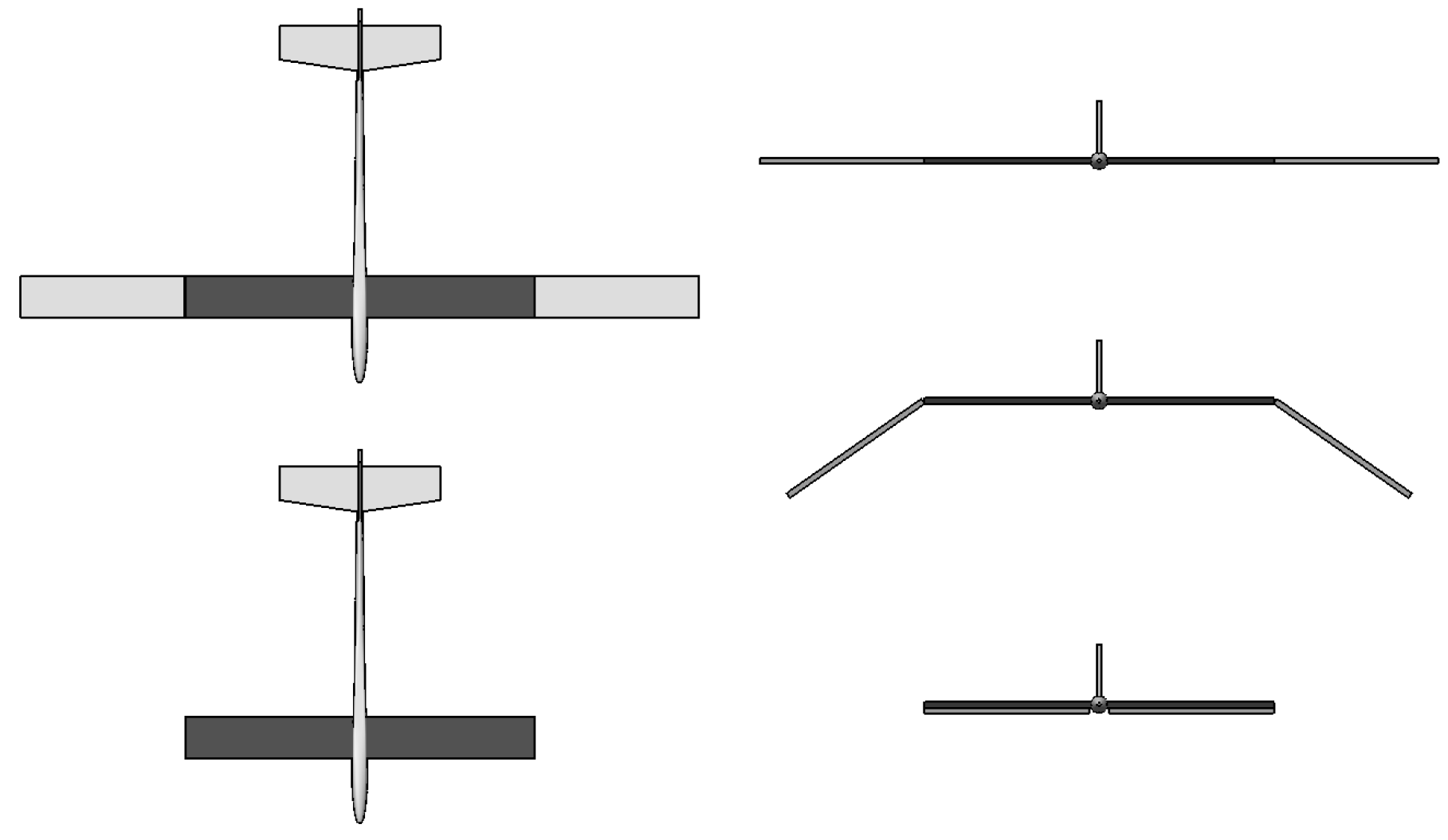
Figure 1. Morphing concept front view top view (left) Morphing concept front view (right).
Aerospace 06 00085 g001
Figure 2. Schematic airfoil configuration at the glider (top) and aerobatic phases (bottom).
Aerospace 06 00085 g002
Figure 3. Mission profile of a surveillance UAV.
Aerospace 06 00085 g003
Figure 4. Mission profile of an attack plane.
Aerospace 06 00085 g004
Figure 5. Required power vs. velocity for the glider and aerobatic configurations at specific wing load and aspect ratio.
Aerospace 06 00085 g005
Figure 6. Block diagram of the morphing efficiency analysis phases.
Aerospace 06 00085 g006
Figure 7. Morphing efficiency vs. wing loading at A R g = 8 and χ = 0.6 .
Aerospace 06 00085 g007
Figure 8. Morphing efficiency over standard glider vs. aspect ratio.
Aerospace 06 00085 g008
Figure 9. Morphing efficiency over standard aerobatic aircraft vs. aspect ratio.
Aerospace 06 00085 g009
Figure 10. Ψ a vs. aspect ratio and several morphing mechanism weight at flight scenario χ = 0.7 .
Aerospace 06 00085 g010
Figure 11. Ψ g vs. aspect ratio and several morphing mechanism weight at flight scenario χ = 0.2 .
Aerospace 06 00085 g011
Figure 12. Proposed morphing algorithm.
Aerospace 06 00085 g012
Figure 13. Roll moment of a folding wing and a second lagging wing vs. angle of anhedral.
Aerospace 06 00085 g013
Figure 14. Elevon deflection angle vs. Δ Γ for several horizontal tail volume.
Aerospace 06 00085 g014
Figure 15. Airfoils samples, originally selected for high velocity (right) and their resulting airfoil upon unfolding (left).
Aerospace 06 00085 g015
Figure 16. Airfoils samples, originally selected for glider aircraft (left) and their resulting aerobatic airfoil upon folding (right).
Aerospace 06 00085 g016
Figure 17. Closing of a ClarkY 9% airfoil using an upper or lower section and a NACA 4 digit approximation.
Aerospace 06 00085 g017
Figure 18. Definition of parameters for thickness reduction method.
Aerospace 06 00085 g018
Figure 19. Visualization of thickness reduction as a mean to reduce leading edge gap.
Aerospace 06 00085 g019
Figure 20. Models for wind tunnel testing: ClarkY 9% (top), G2A30.7 (middle), G2A0.0 (bottom).
Aerospace 06 00085 g020
Figure 21. Test model wing section construction.
Aerospace 06 00085 g021
Figure 22. G2A30.7 wing segment fixed to the test apparatus during wind tunnel test.
Aerospace 06 00085 g022
Figure 23. Lift coefficient vs. angle of attack comparison of the four tested wing segments.
Aerospace 06 00085 g023
Figure 24. Drag coefficient vs. angle of attack comparison of the four tested wing segments.
Aerospace 06 00085 g024
Figure 25. Pitch moment coefficient vs. angle of attack comparison of the four tested wing segments.
Aerospace 06 00085 g025
Figure 26. Smoke aided wind tunnel test result on a G2A30.7 model.
Aerospace 06 00085 g026
Table 1. Aircraft main characteristics.
Glider (g)Aerobatic (a)Value
b b 2 Wingspan
A R A R 2 Aspect Ratio
S S 2 Wing Area
w s 2 w s Wing Loading
t 2 t Airfoil Thickness
Table 2. Experimental main aerodynamic parameters.
ParameterClark Y 9%G2A 0.0G2A 30.7Closed G2A 30.7
C l α [ 1 / r a d ] 3.51 3.35 2.81 2.87
C D 0 0.05 0.01 0.02 0.02
C M 0 0.04 0.009 9.4 × 10 5 0.001
C l m a x 1.10 0.87 0.58 0.61
α s t a l l [ d e g ] 16.4 16.0 13.7 12.5