1. Introduction
Simple manoeuvres are commonly used when assessing aircraft handling qualities of civil aircraft [
1,
2,
3]. Only a few complex and demanding tasks, more representative of mission requirements, are widely accepted and documented, such as the the Offset Landing Manoeuvre (OLM) [
4] or horizontal S-turn, both flown in near ground conditions. This paper presents an expansion of the OLM for civil aircraft handling qualities assessments: the Slalom and Alignment Tracking (SLAT) task. This multi-directional manoeuvre was designed as a slalom which can be performed at different altitudes and airspeeds as visual cues are positioned and scaled in the environmental display as a function of test conditions. A significant workload from the pilot is required, as he/she is tasked to fly through a series of scalable banking turns and alignment tracking phases. The scaling is done through a sizing method, specifically designed for the manoeuvre which allows for varying manoeuvre intensity and difficulty levels despite varying simulation conditions (known to decrease pilot sense of immersion, stress and/or engagement in the test [
5]. This in turn ensures nominal pilot inputs range from lower to higher gains spectrum as required for the on-going test. Moreover, the manoeuvre is intended to be used as an expansion or replacement of existing complex near-ground manoeuvres with a clear advantage as different altitudes and airspeeds can be simulated. It can also help confirm findings from simple open-loop tests. Overall, this work was intended as an attempt at unifying a handling qualities assessments campaign under a single methodically scaled and tailored complex manoeuvre (without disregarding simple open-loop tests if required).
After introducing the motivation for manoeuvre development in
Section 2, the manoeuvre general description and methods used to size the manoeuvre are given in
Section 3. The implementation within the simulation tools, as well as initial verification and manoeuvre geometry feedback are highlighted in
Section 4. The applicability of the manoeuvre for aircraft handling qualities assessment is then presented in
Section 5 based on test cases and simulation campaigns. Fifteen participants including two test pilots and a commercial pilot were invited to participate in the study mainly based around two aircraft models. A single wing configuration and a handful of altitudes (
h = 2500 m and
h = 5000 m) and airspeeds (
= 150 m·s
and
= 200 m·s
) conditions were used to highlight appropriate test conditions. A final discussion regarding manoeuvre suitability and relevance as a complex manoeuvre for handling qualities assessment is then made in the conclusion of this paper.
2. Motivation for a New Manoeuvre Development
2.1. Historical Development of Handling Qualities Investigations
Aircraft handling qualities were widely misunderstood at the early stages of aviation [
5,
6,
7,
8]. Pilot hands-on flight experience did not match theoretical predictions and understanding of desirable aircraft manoeuvrability derived from the equations of motion [
9] and what theoreticians understood as desirable aircraft manoeuvrability. In fact, early pilots who managed to survive long enough were ultimately forced to cope and master their vehicles’ handling qualities [
5,
7] rather than the other way around. Therefore, the first descriptions of aircraft behaviour were unsurprisingly made from pilot observations. This led to empirical theories mostly based on what appeared as common sense, though a number of classical misconceptions still taught today were identified in Gibson’s work [
5,
7].
Not until the stability equations were derived did theoreticians became capable of predicting and designing desirable aircraft handling characteristics. The proliferation of aircraft configurations and models encouraged by WWI and WWII allowed experimental verification and establishment of a supposed link between speed, manoeuvre stabilities and desirable aircraft handling. One of the first notable attempts to correlate in-flight measurements with pilot opinions focused on the long period and short period dynamics of a small number of biplanes and monoplanes [
10], though the study failed to capture any correlation between longitudinal stability and pilot opinion and feedback. This lack of understanding between pilot and engineers on desirable handling qualities was pointed out at the time [
11] and progressively bridged as more and more pilot opinion based studies were carried out [
12,
13]. Most importantly, the lack of written definition and requirements for satisfactory performances was highlighted [
14]. Thus, the first requirements for what would later become handling qualities were formulated for longitudinal, lateral dynamics and stall conditions. The 1940s and 1950s led to numerous experimental investigations, using both qualitative (measurements) and quantitative (pilot opinion) analysis and comparison methods. Other notable investigations include the study of the effect of dihedral changes on lateral stability for a variable stability aircraft [
15,
16]. Moreover, the longitudinal handling qualities for a modified variable longitudinal stability jet fighter [
17] were assessed as a stiffness factor through qualitative feedback. Similar longitudinal stability assessments were made on a B-26 bomber, with a comparable methodology [
18]. Finally, and to cope with changes in design and operational use of a variety of aircraft, an evaluation of multiple representative vehicles was made still using pilot opinions and feedback [
19] in an attempt to unify the methods and conclusions of handling qualities work. The reader is referred to excellent summaries of historical development and progress into static and dynamic stability theories (central to early methodical research efforts to understand and limit undesired behaviours) [
5,
6,
7] for more in depth reading.
2.2. The Qualitative Cooper Harper Rating Method
A variety of analysis methods, both in the time and frequency domain emerged to help engineers rate aircraft handling qualities based on quantitative data, such as the Control Anticipation Parameter (CAP), Gibson Drop back or Neil–Smith Criterion. Based on what was already two decades of documented testing, a method known as the Cooper Harper Rating (CHR) scale [
20,
21] was developed in the late 1960s to help in the comparison and standardisation of ratings between pilots and aircraft handling qualities for qualitative data.
The methodology, still widely used today, helps flight test engineers and test pilots assess aircraft performance to specific task or manoeuvre by setting clear targets and desirable performance definitions. Pilots are required to make binary decision regarding the aircraft performance for the task at hand, and identify if the vehicle is controllable, if adequate performances were achieved and if improvements are required for the vehicle. In this qualitative rating method, the pilot opinion rated against a universal scale: a rating from 10 (impossible to fly) to 1 (excellent, highly desirable) is then given to rate the aircraft capability to fly a specific mission task. Note that uncertainty will arise as a function of pilot objectiveness, training, understanding of the scale, and adequacy of the test for a CHR rating. Therefore, this method requires significant training and flight experience to be properly used as a comparison tool between aircraft and pilots. Of course, the scale and rating should not supersede any type of pilot feedback. In fact, these comments should be used as a catalyst for methodical assessments and precise understanding of the rating [
20,
21]. Thus, the definition and understanding of the task must be clear if a CHR is used with test pilot participants. When pilots without any testing experience are used, basing a handling qualities rating on a CHR can be ambiguous if not misleading.
2.3. Flight Simulators and Pilot Models
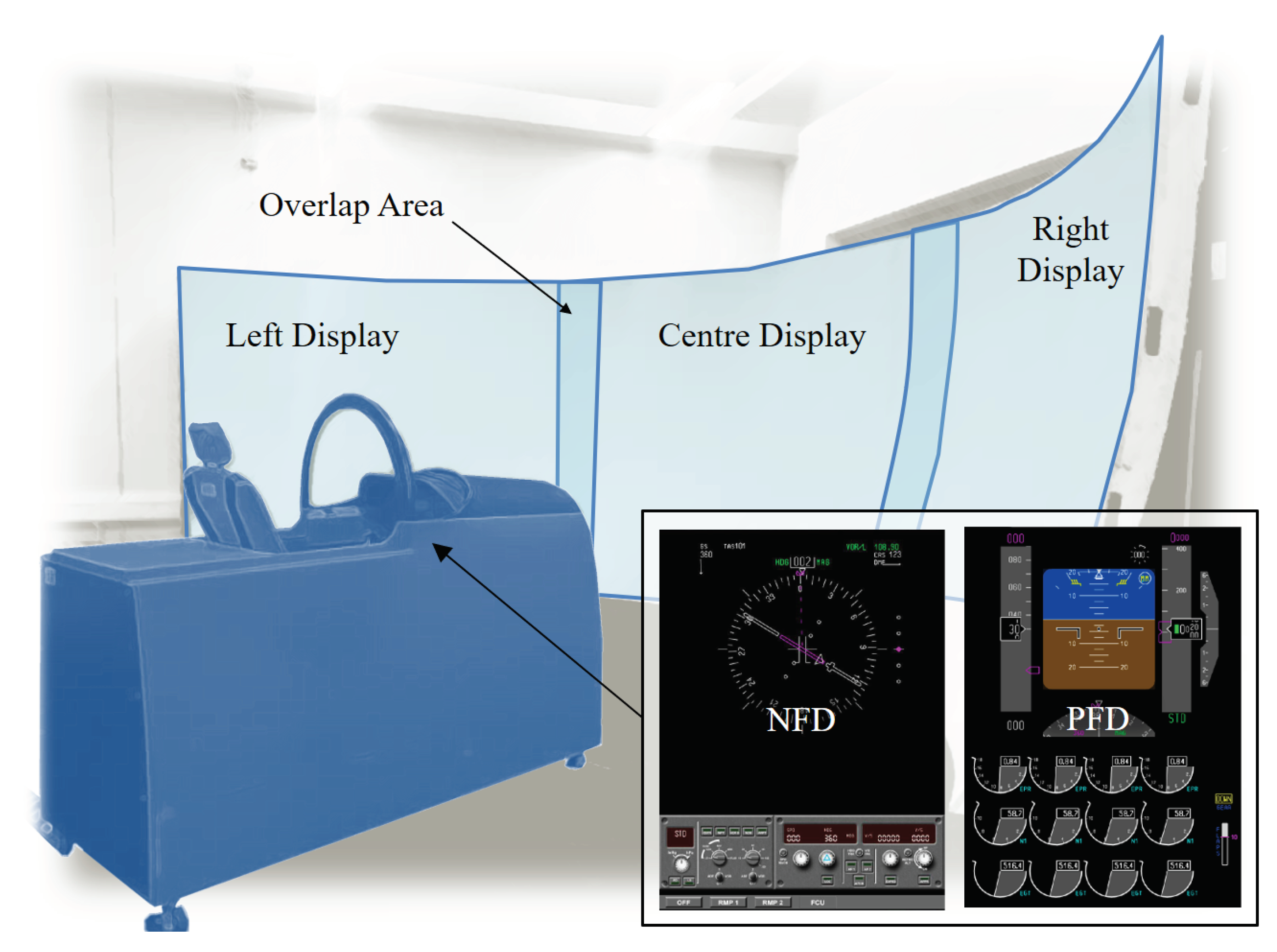
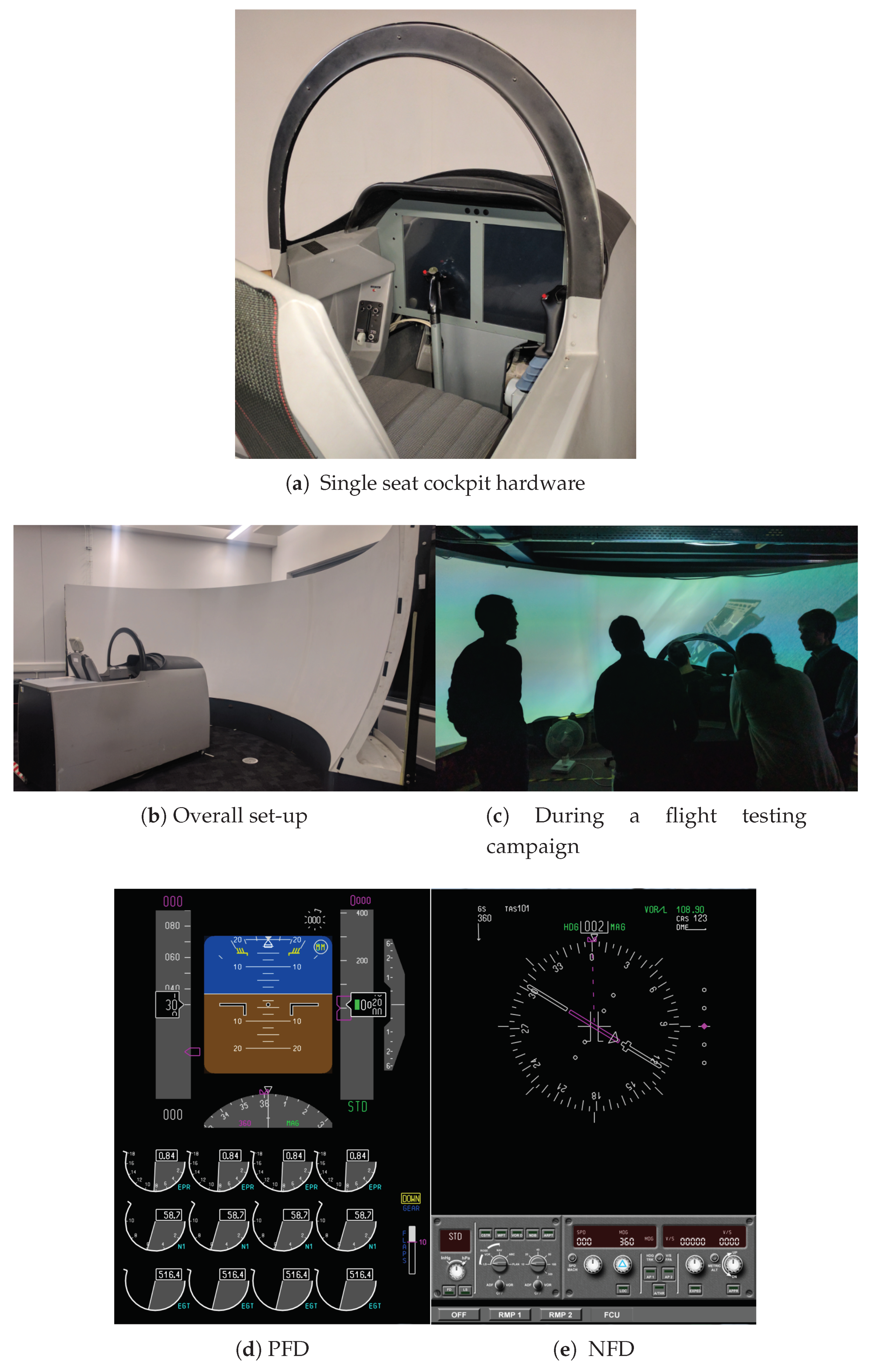
In parallel to handling qualities development, ground based flight simulators started to become a major part of flight control development and clearance for new designs. Basic shapes on analogue single television screens were initially used to display visual cues to pilots. This generated suitable preliminary testing conditions but failed to put pilots in realistic stress levels that only real flights could provide. Over the years, wider environmental displays and greater fidelity improved pilot immersion, to current standards or realistic world and cockpit displays (both software and hardware related).
Overall, flight test and simulation results are known to display variations in pilot behaviour, with a relaxed aggressiveness and reduced pilot gain in the latter [
4]. Unsurprisingly, stress and sense of urgency (core elements of handling qualities assessments [
4,
5,
20]) are drastically reduced in simulation conditions. This phenomenon is further intensified during less stressful situations such as on high altitude flights or when clear of any nearby obstacle.
Motion capable simulators and less common in-flight simulations through variable stability aircraft [
22] also enabled testing with much required realistic pilot environments [
3,
5] requiring less corrections to the data set obtained through simulation before comparisons with real flights.
The introduction of theoretical pilot models also allowed for a significant breakthrough in handling qualities research and systematic use in aircraft design. At first, simple models proved to be sufficient for low order dynamic manoeuvres, allowing for preliminary research without pilot-in-the-loop simulations.
It was demonstrated very early, however, that pilots showed highly nonlinear controls, especially when faced with demanding tasks and high order dynamics. When under excessive work loads, pilots often fall back to simpler control command schemes using discrete or “on-off” inputs to reduce required control efforts [
23,
24]. Additionally, simple pilot models are still often constrained to specific flight conditions [
25] or manoeuvres even though developments for adaptive pilot models have emerged [
26]. The impact of training and task recurrence on pilot performance compared against pilot models has been highlighted on multiple occasions [
23,
27]. The latter reference highlighted the needs to keep pilot-in-the-loop simulations within the aircraft design process and not rely solely on pilot models despite more recent developments.
2.4. Existing Certifications and Manoeuvres for Handling Qualities
Key development information and valuable aircraft characteristics can be derived from simulation of specifically designed manoeuvres and testing methods. Military requirements offer a wide range of complex manoeuvres including in-flight refuelling, air-to-air and air-to-ground tracking [
28]. Even more examples can be found in rotary wing aircraft certification and testing documents [
29]. However, some of these manoeuvres are not necessarily relevant to civil applications and adequate certification methods include only simple manoeuvres with very specific and restrained objectives [
1,
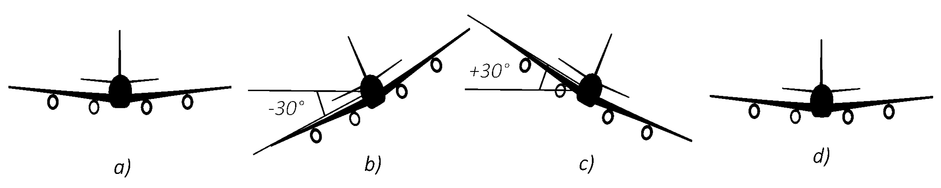
2]. Simple open-loop response tests are widely used. In lateral dynamics for instance, the civil requirements address mainly roll performance in terms of control power. The ability to roll through 60
(typically from 30
bank one way to 30
bank the other as illustrated in
Figure 1) at a specified airspeed and configuration in less than a specified time is a required test. However, no requirements on any particular bank angle capture are given, other than the achieved rate of roll must be sufficient as implied by the requirements. The roll time constant established as 0.63 of the time to establish maximum roll rate can be identified with the above. Note that an aircraft may fail this test if aileron effectiveness (
) is insufficient or if excessive adverse yaw (
) combined with dihedral effect (
) overpowers
contribution and prevents the aircraft from rolling from and to the required delta in the specified time. The simplicity of manoeuvres used in civil aircraft handling qualities and flight dynamics compared to military aircraft [
28,
30] can be linked to a more precise certification and simpler mission characteristic requirements in the first category. Moreover, the lack of a common and more complete database, similar to those found for military applications [
28,
29] can be outlined.
Adaptations of complex multi-directional manoeuvres for civil aircraft handling qualities assessment have been flown in the past [
4]. Near-ground lateral S-turns, vertical offset and Offset Landing Manoeuvre (OLM) are used for landing handling qualities and Pilot Induced Oscillation (PIO) investigations [
4]. These manoeuvres are difficult by definition due to environmental conditions in which they are flown. Clear sizing definitions have also been made to facilitate standardisation of the results. As a result, these manoeuvres are now commonly used in simulation environments for low altitude testing of multi-directional dynamics and are in fact arguably the most challenging tasks widely used today in civil flight simulation.
2.5. Motivation for Manoeuvre Development
In these near ground manoeuvres, pilots tend to display more aggressive responses, allowing higher order characteristics to be captured. At higher altitudes, in-flight refuelling or formation flight could be used to drive similar pilot high gain responses. In these scenarios, however, visual targets (or leading aircraft) must be used which can be complex to implement successfully. Furthermore, a lack of standardisation in manoeuvre length, path definition and testing procedures other than alignment tracking can be outlined. In fact, the authors are unaware of standard manoeuvres or testing procedure to assess multi-directional handling qualities of the aircraft at various altitude levels whilst keeping the pilot under sufficient yet realistic work load and urgency conditions.
The potential use of flight simulation as an aircraft design and research tool, the limited number of complex manoeuvre options and lack of applicability of the OLM to a wide range of altitudes highlighted the need for the development of a new manoeuvre, used in correlation with existing qualitative analysis (CHR) and quantitative data processing methods. The authors therefore worked on the development and testing of a new multi-directional manoeuvre, the SLalom and Alignment Tracking (SLAT) tack.
3. Description of the Manoeuvre
3.1. Manoeuvre Design Requirements
The authors believe that using a single multi-directional manoeuvre scaled to match feasible trajectories at various airspeeds and altitude could help unify handling qualities assessments under a single simple method. Such a task would engage pilots in more realistic and stressful piloting conditions instead of simple open-loop tests whilst still highlighting dynamics of interest. Similar benefits to the Offset Landing Manoeuvre (which arguably unified handling qualities assessments in landing configurations to a single widely used task) are expected. The task could also be designed to stimulate pilot inputs from the lower to higher frequency spectrum. The manoeuvre could also be used to confirm findings of simple open-loop tests or simply serve as an alternative option to other manoeuvres where similar dynamics are investigated.
The manoeuvre must therefore be performed at different airspeeds, altitudes and flight configurations. Manoeuvre geometric parameters must therefore adapt to flight conditions to maintain consistent desirable and acceptable feasibility and maintain a manoeuvre baseline shape and trajectory. The manoeuvre requires high pilot engagement and clear performance indicators for both the pilot and engineers responsible for data processing, likely based on environmental cues. By changing tolerances in performance metrics during the manoeuvre, task difficulty should also be modified, thus impacting the required pilot performance. To meet the above requirements, the SLAT manoeuvre was designed.
3.2. General Description
The
SLalom and Alignment Tracking (SLAT) task was designed as a slalom and multi-directional manoeuvre, where a couple of specific mission capabilities are monitored repeatedly throughout the task. These include gross position acquisition and fine alignment tracking. Where a slalom task as intended for rotary aircraft [
29], or large civil transport plane (S-Turn) [
4] would use ground references to size the manoeuvre and help in the performance assessment, alternative visual markers must be considered for application at different altitudes. Visual targets such as checkpoints or flight path boundaries are relatively easy to implement within a flight simulation environment and were therefore prioritised for this slalom manoeuvre. By changing tolerances in the manoeuvre, such as minimum or maximum banking angle during a turn, checkpoint size and position, it was also estimated that task difficulty could be modified, impacting the required pilot performance based on clear metrics.
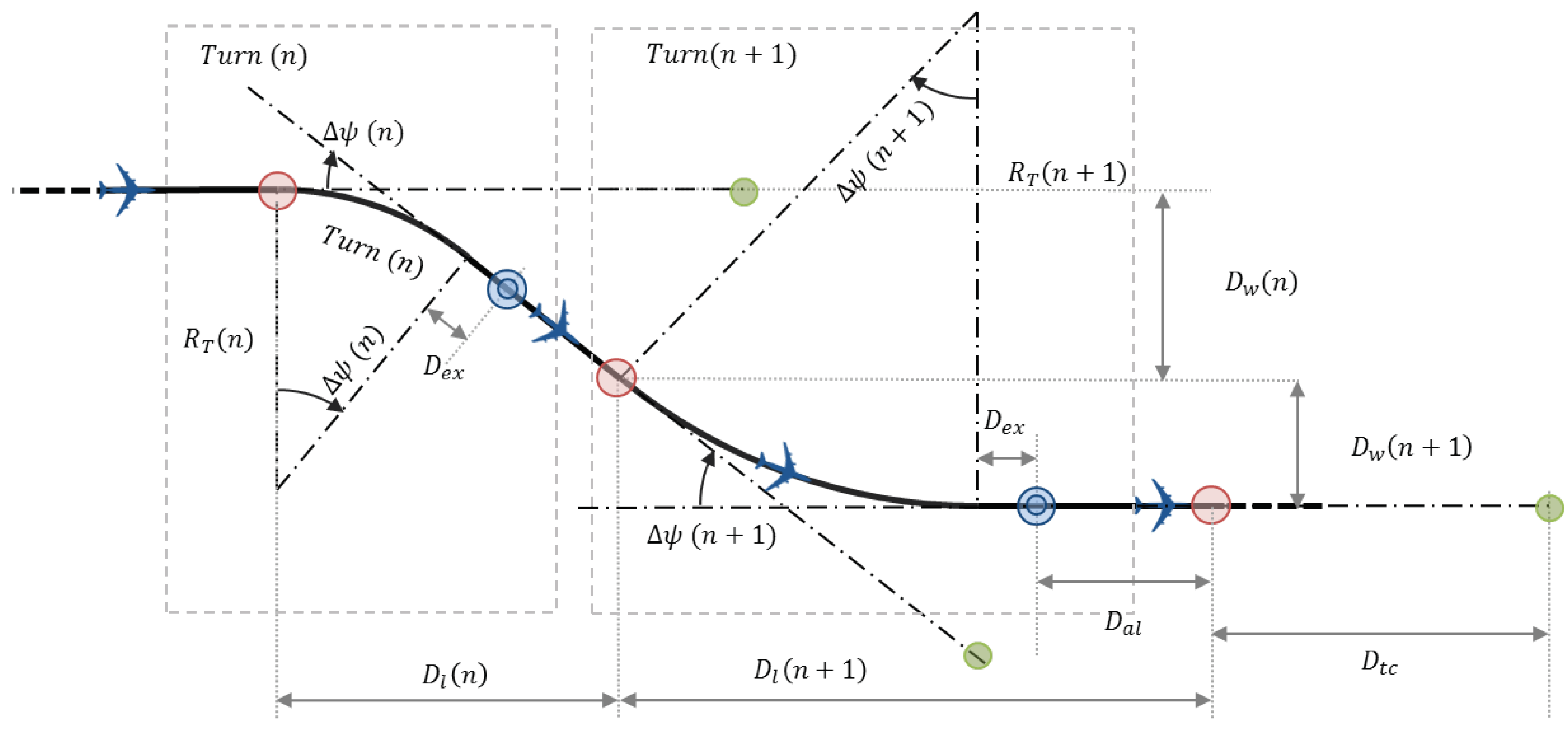
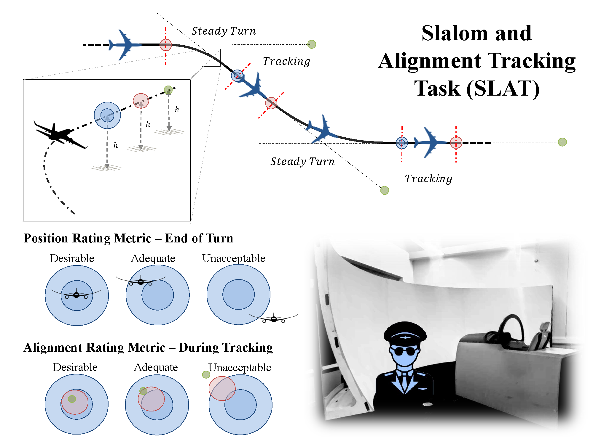
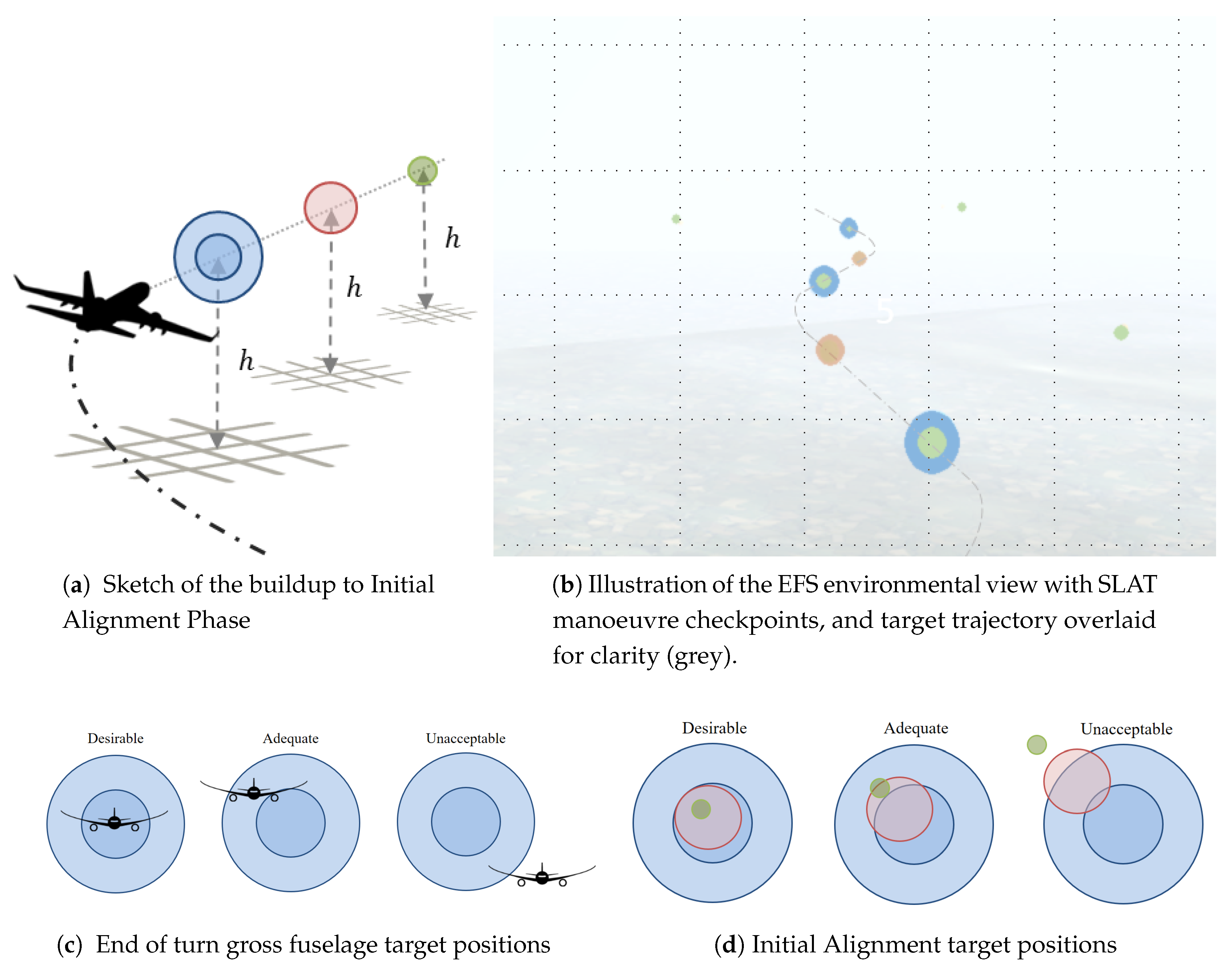
The SLAT manoeuvre is divided into a series of sections each comprised of a turn phase and an alignment phase, where targets for both mission capabilities are established. An illustration of two subsequent sections is given in
Figure 2. The steady banking turn, flown at constant altitude and airspeed, is used to engage lower order pilot dynamics. The turn is engaged from a wing’s level position upon entering the appropriate gate or checkpoint (red marker in
Figure 2). The lateral dynamics such as roll damping or aileron effectiveness are assessed as the pilot engages, stabilises and maintains the turn for a specified time. The pilot then exits the turn, wing level, at the dedicated checkpoint (blue marker in
Figure 2). Gross position and attitude are monitored at the end of the turn as the aircraft is flown through the turn exit marker (blue). Two co-centric spheres are used to define desired, adequate and unacceptable performances, as shown in
Figure 3c. Aircraft centre of gravity (CoG) position is used to qualify performances when using simulation data analysis, whilst pilot feedback is obviously based on cockpit based perception. The manoeuvre is designed so that the pilot disengages the turn phase as he aligns both the following section start gate (red marker) and the alignment reference marker (green), as shown in
Figure 2 and
Figure 3a. The aircraft is then flown in steady level flight whilst maintaining alignment of both red and green markers. Using visual cues from upcoming gates as shown in
Figure 3d defines the desirable, acceptable and undesirable alignment performances. The pilot is then tasked to maintain alignment whilst an eventual briefing/discussion is made over the performances of the latest and/or upcoming section. The next section starts upon reaching the red marker used during the alignment.
When flying with test pilots, a CHR rating can be made on the following (but not limited to) performance metrics: gross position, initial alignment and alignment tracking. Pilot opinions and feedback are also gathered on specific section and overall manoeuvre performances. Coupled with flight data recording, handling qualities assessment can be made. The breakdown into different sections allows for various task difficulties to be tested and should therefore be evaluated individually by the pilot.
A manoeuvre description sheet can be found in
Appendix A written in a comparable format to other documents found in the literature [
30].
3.3. Manoeuvre Geometrical Layout Sizing Method
A realistically feasible handling qualities manoeuvre at different flight conditions must be sized properly. Therefore, the SLAT manoeuvre uses a number of parameters to adequately position and size the various checkpoints and ensure feasibility. Parameters such as turn radius of a section n are predicted as a function of desired bank angle and airspeed, or load factor. Position of the turn exit marker will also vary on the desired heading angle change or steady turn hold time. Additional spacing between the gates is accounted for dynamic behaviours, such as roll dynamics of the banking manoeuvre. Overall, distances such as longitudinal and lateral distances between two sections and , respectively and can be parametrised by turn characteristics and , as well as additional spacing for dynamic behaviour before and after the steady turn . A distance allocated for alignment tracking and distance of the reference marker is also included and parametrised as a function of desired manoeuvre difficulty. Radii of all spherical checkpoints and markers were selected so as to be visible from required distances and be of relevant sizes relative to the aircraft and task difficulty. The red marker initiating the turn phase of each section was given a radius of = 50 m. Larger than a conventional runway width, this gives enough tolerance for the pilot to fly through without excessive difficulty. The blue marker ending the turn phase of each section was given an external radius of = 100 m, and an internal radius of = 50 m. The larger size allows for more tolerance and visibility when assessing the manoeuvre. The green marker used for alignment tracking was given a radius of = 25 m. As this marker is not used as a fly-through checkpoint and positioned relatively far from the optimal trajectory, visibility is the dominant sizing parameter. The marker must be sufficiently large to be seen from the required distance () yet not conflict with other markers during the manoeuvre. Note that the marker distance is linked to acceptable and desired initial approach angle through a geometric analysis.
In order to adequately size the manoeuvre, two simplified models are used, relying respectively on (a) forces equilibrium and pilot training notions/calculations for steady turn sizing, and (b) state-space models for transient unsteady dynamics capture and link to aerodynamic coefficients and derivatives. Combined, these models allow for accurate and realistic manoeuvre sizing with notions that both pilots and flight engineers can understand and verify with typical back of the envelope calculations.
3.4. Sizing the Steady Turn
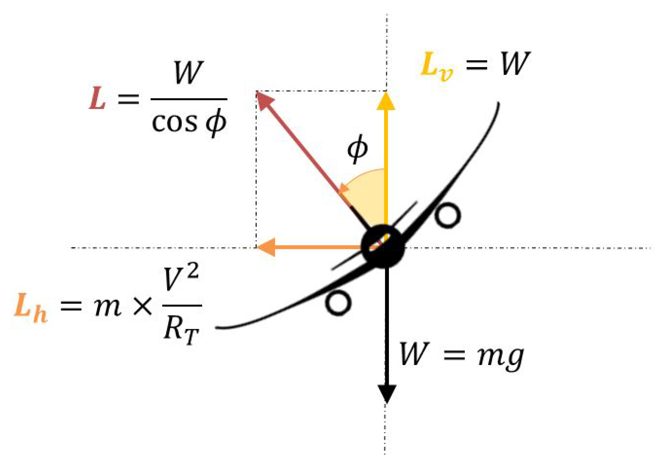
A rather simplistic point mass model, which effectively corresponds to what a pilot conventionally uses as back of the envelope calculations when sizing simple manoeuvres, was found suitable in sizing the steady turn phase of the manoeuvre. With such a simplified hypothesis, the aircraft is assumed in a steady banking turn as shown in
Figure 4, with centripetal acceleration
in a steady turn of radius
flown at a constant airspeed
V given by Equation (
1), and centripetal lateral force
by Equation (
2), where
m is the total aircraft mass. To maintain altitude, the vertical component of lift
must balance the weight of the aircraft
W. On the other hand, total lift and therefore load factor will increase with bank angle. Hence, for any aircraft, bank angle
corresponds a single load factor
for a steady state constant altitude turn and given
set. From Equations (
1)–(
4), a direct link can be made between
and therefore
for a given manoeuvre airspeed. Turn radius to match bank angle or load factor targets can be predicted for realistic commercial flight conditions, or any desired more aggressive manoeuvring. Using airspeed and turn radius, heading change rate
can easily be extracted using Equation (
5). Using Equation (
6), it is then possible to size the turn to match a desired turn time
or heading change
. Examples of parametrisation results from these equations are given in
Table 1 for four different examples. These were obtained using Equations (
1)–(
6) and clearly show (as expected) that, in the case of a steady turn at constant altitude: (a) airspeed does not change load factor but increases turn radius, (b) increasing allowable load factor leads to higher bank angles and higher heading change rates:
3.5. Sizing the Dynamic Roll Phases
In the case of the SLAT task, aircraft dynamic behaviour in roll is also of paramount importance. A state space formulation of aircraft coupled lateral-directional dynamics based on non-dimensional aerodynamic derivatives [
31,
32] can be used to predict the dynamics of an aircraft around particular equilibrium points and flight conditions. Note that similar data sets are used in most conventional flight simulators such as the one used herein and introduced in
Section 4.1 and previous work by the authors [
33,
34].
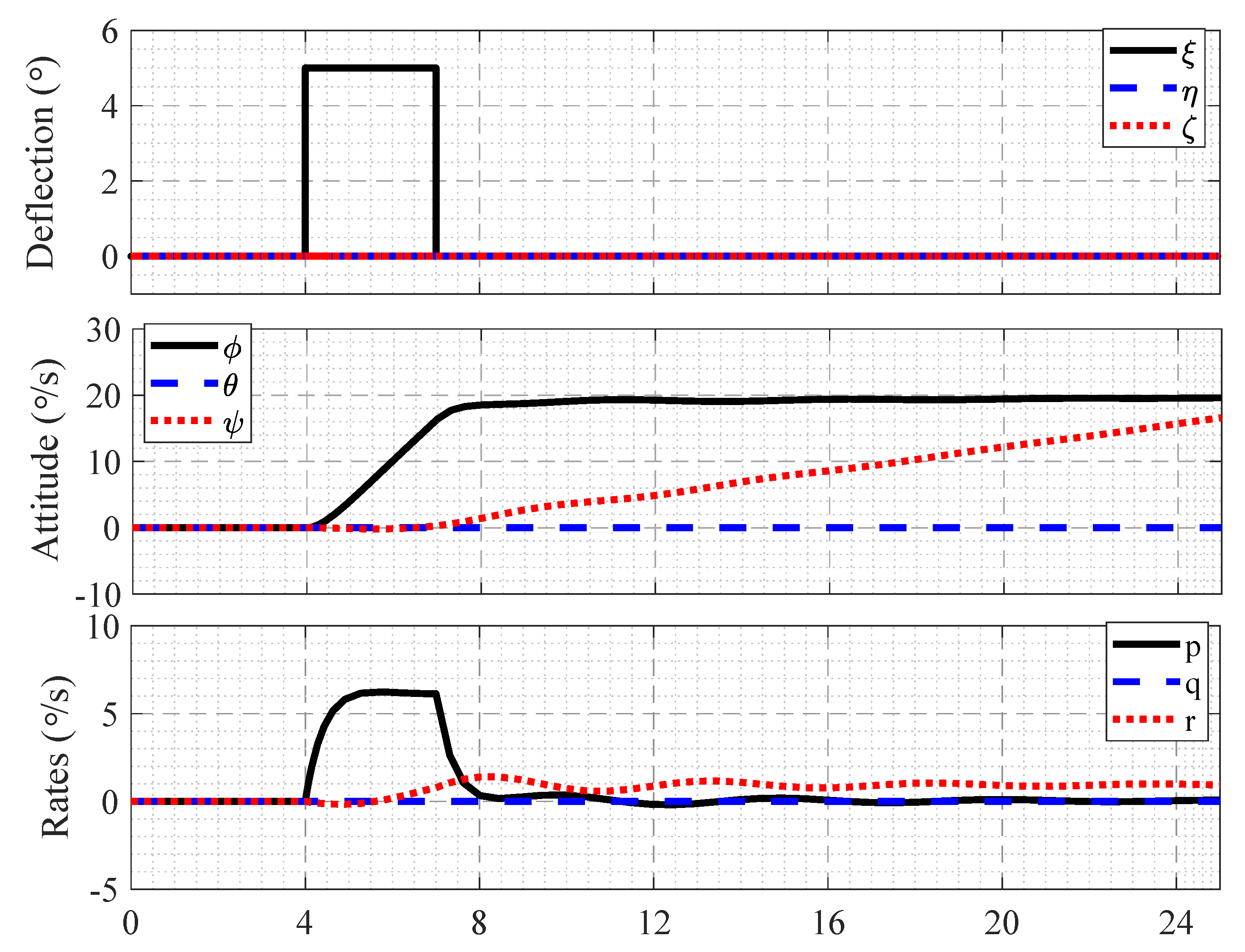
A dedicated simple state-space model, decoupling lateral-directional and longitudinal dynamics for simplicity, was built to predict aircraft response to any directional control input. Aircraft time to reach desired bank angle rate and roll rates can therefore be extracted to size the rest of the manoeuvre, assuming adequate aerodynamic derivatives are used. If changes are made to aircraft layout leading to reasonable shifts in aerodynamic derivatives, such as roll damping
or aileron effectiveness
, these can easily be changed and the manoeuvre resized appropriately. For instance, folding wingtips were shown to lead to changes to aileron effectiveness and roll damping in past published work [
35,
36] which could theoretically jeopardise the feasibility of the manoeuvre if sized for the baseline aircraft. The state space model can therefore help in gate placement as well as predict manoeuvre feasibility prior to any pilot in the loop simulations, making it a very useful sizing tool for the SLAT manoeuvre. Example of time histories from the state space model for a large generic aircraft are given in
Figure 5, illustrating aircraft dynamic behaviour. Buildup times from wings level to design bank angle and aircraft velocity are used to approximate the additional distance
for each section of the manoeuvre, required to allow dynamic aircraft behaviour.
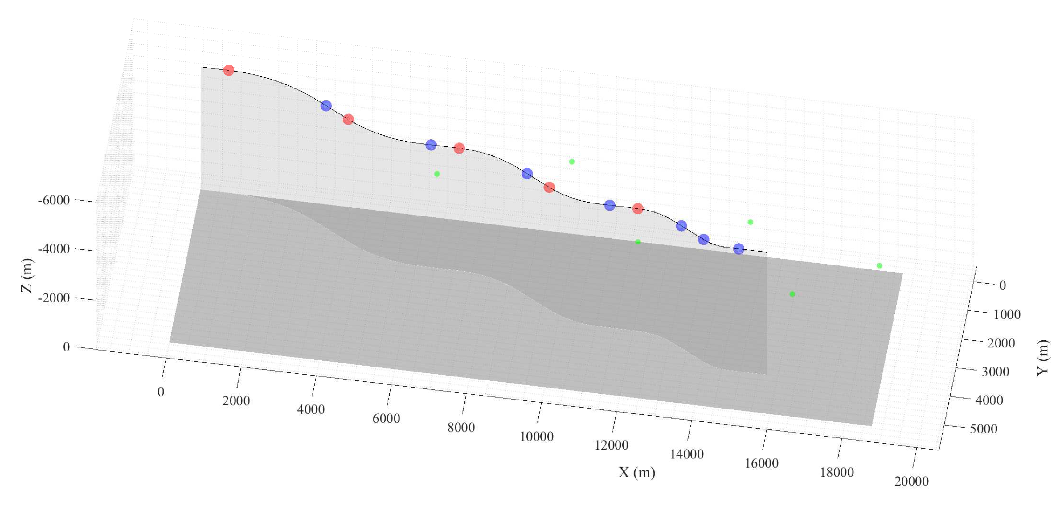
Finally, the multi section manoeuvre can be sized by combining both models. Pilot aggressiveness and task difficulty can be changed for each section independently, modifying either bank angle, time to hold, time to roll, tracking length, and marker size and position. An example of a six section manoeuvre is given in
Figure 6, with progressive banking angle increase, ranging from
to
at 150 m·s
and an altitude of 5000 m, leading to successive steady turns with vertical load factors
from 1.1 g up to 2 g. The checkpoint marker (red for the start and blue for the end of the steady turn) as well as the alignment tracking marker (in green) positions along the manoeuvre predicted trajectory are shown in the latter illustration.
5. Simulation Campaign Results
Different investigations were carried out to validate the applicability of the manoeuvre, compare handling qualities and flight dynamics of two commercial aircraft, assess the impact of folding wingtips on a large civil aircraft handling qualities and investigate a very flexible High Aspect Ratio Wing (HARW) concept. Details of the purpose of each test, participating pilot details and results will be discussed.
5.1. Example of Manoeuvre Test Result
First, the results of a specific manoeuvre are given herein for illustrative purposes. It is important to highlight typical results obtained during the development phase and verification of the adequate implementation of the entire simulation process. As stated in
Table 3, the results presented herein are those of test flown by a licensed pilot with some experience in small aircraft flight, as well as flight simulator training for large transport aircraft certification. This particular example corresponds to one of the final verification runs, where the pilot highlighted some interesting discussion points during debriefing. Whilst this particular example does not bring an astute qualitative analysis on the aircraft handling qualities, it is valuable in highlighting the impact of pilot skill and experience on task feasibility and overall performances.
For this simulation campaign, the pilot was briefed on target heading changes, bank angles, altitude and airspeed prior to the experiment. The manoeuvre parameters and test conditions are given in
Table 4. The task was designed as a succession of two
and two
banking turns in opposite directions alternatively. A tracking time of 15 s was used between two subsequent sections. An altitude of
h = 5000 m and
= 150 m·s
in a clean wing configuration was selected for this test corresponding to realistic flight conditions for the Boeing B747 aircraft model which was used. Sufficient acclimatisation time with the aircraft model was given with approximately 10 min of practice time in free flight and a couple of practice runs on a simple substitute SLAT geometry.
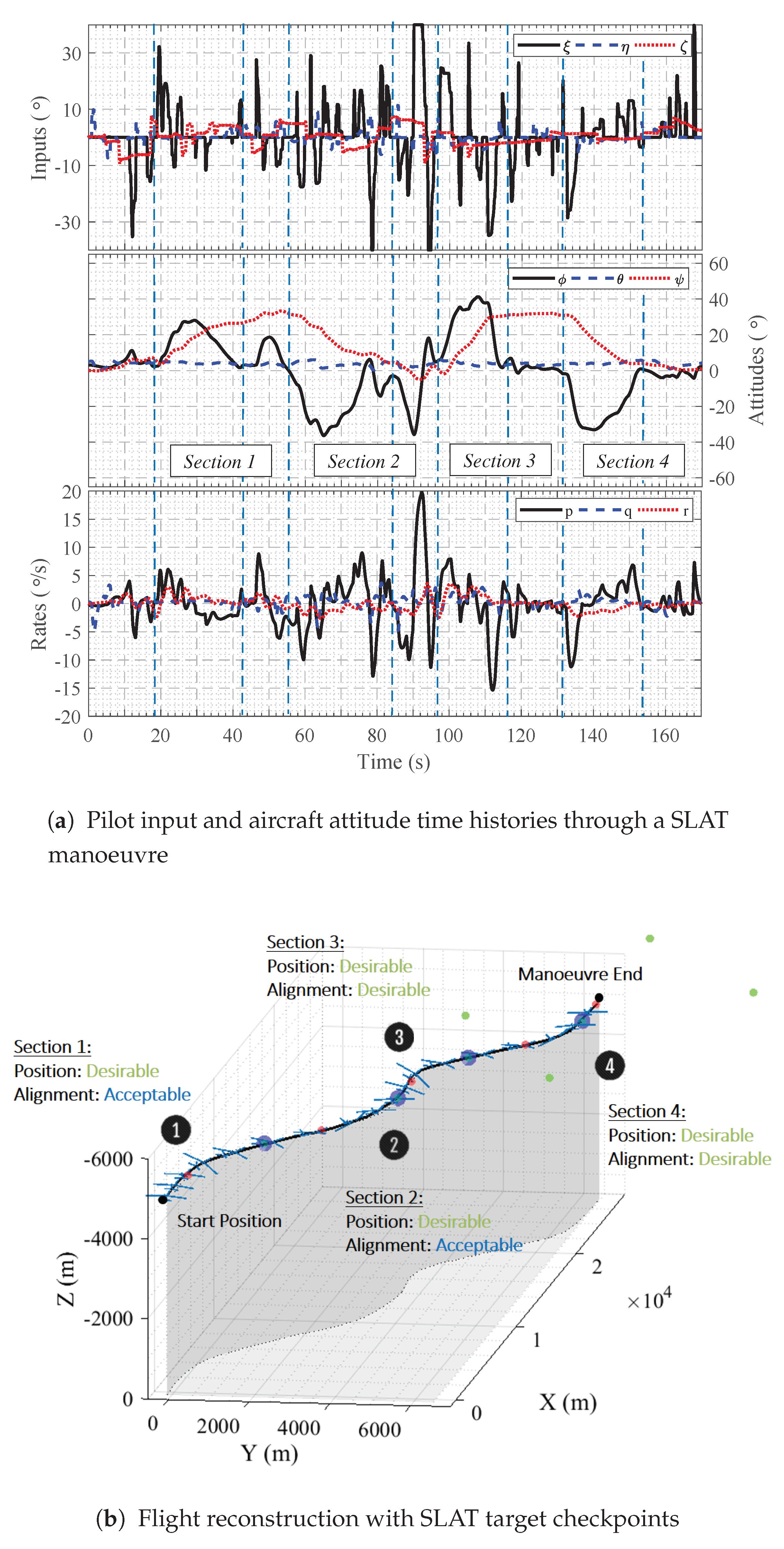
Quantitative recording of the manoeuvre is given as time histories of aircraft states and pilot inputs in
Figure 8a.
Figure 8b shows the flown trajectory (in black) and ideal target marker positions for the simulation. The qualitative performance rating regarding position and tracking tasks are also given in the figure and were assessed during the flight by both pilot and simulation engineer. Note that as these results were not obtained with a certified test pilot, no Cooper Harper rating was given regarding the aircraft due to lack of method knowledge from the pilot.
On the other hand, pilot feedback both during and after the manoeuvre as well as quantitative data analysis can be used to verify task performance for each section of the manoeuvre. In this particular run, Sections 1 and 2 defined respectively from
t = 18 s to
t = 55 s and
t = 55 s to
t = 95 s proved surprisingly more challenging for the pilot than expected. Effectively, the aircraft bank angle and heading change rate was initially higher than required which led to a smaller turn radius and a faster heading change than desired. Thus, the pilot was tempted to disengage the turn and attempt to correct position and alignment as he reached the position and alignment assessment marker at the end of the turn, where a desirable position was achieved. However, heading alignment at both checkpoints were estimated to be only acceptable. In fact, the initial alignment at the end of the turn meant that significant corrections by the pilot were required to obtain and maintain correct alignment during the fine tracking. For Section 1, a progressive return to wing level before the checkpoint and gross position performance acquisition was followed by significant repositioning efforts during the alignment phase due to the degraded initial attitude at the start of the tracking phase. This correction is even more drastic for the second section of the manoeuvre from
t = 85 s to
t = 95 s. The pilot noted a similarity of the incident with the realignment procedure during an offset landing manoeuvre, which had been discussed beforehand during the briefing and previously flown by the pilot with the author at Cranfield University. Performance on Sections 3 and 4 were desirable, with no significant effort during the alignment tracking phase due to better steady turn performances as shown in the time histories in
Figure 8a. This was linked by the pilot to the greater bank angle requirement and shorter steady turn phase conditions, ultimately easier to hold.
Note that the effect of dynamic pressure on manoeuvre feasibility can be linked to the performances in the first two sections. It was found that the pilot failed to maintain constant airspeed and more specifically altitude (not shown here) as thoroughly during the longer turn sections compared to the faster roll and more aggressive turns at . Undeniably, changes in airspeed has impacted roll rate as well as turn radius, banking angles and time required to reach target position and alignment. This effectively led to more aggressive inputs in an attempt to recover position and alignment after a deviation from the target trajectory, a phenomenon highlighted by the pilot in the post flight briefing. Pilot lack of reference on bank angle when flying based on environmental cues was also pointed out, which should have influenced performance
Note that the increase in task difficulty and/or pilot aggressiveness as pilot performance drops is a desirable feature of the manoeuvre. To a certain extent, this “cascading” effect, where relatively bad performance in one section leads to a a more challenging recovery phase or even the following section is similar to real flight and specific mission tasks where abort/restart is not an option. Furthermore, the task was designed to force aggressive responses and inputs from the pilot if required, which is what the manual repositioning during the end of the turn and alignment phases created. The “cascading” effect can be used as a desirable performance discrimination tool.
5.2. Evaluation of the Manoeuvre Feasibility Domain
It was seen in the previous example that even the lower banking turns could be challenging to some pilots. The “cascading” effect was also highlighted. Therefore, the feasibility of the manoeuvre can be challenged in some conditions, despite having been designed as a scalable manoeuvre in terms of airspeeds, altitudes, banking and heading changes. Less suitable conditions are expected to be particularly more plausible in the extreme banking turn manoeuvres (high and low banking targets), though they should vary as a function of pilot skill and experience. Thus, a specific testing session was designed to identify the test conditions in which the manoeuvre could be expected to be feasible and useful for a handling qualities assessment, also known as the manoeuvre feasibility domain.
Two pilots participated in this manoeuvre feasibility verification campaign as shown in
Table 3 with a student pilot with large transport aircraft flight simulator experience and a more experienced glider test pilot with a private pilot license and small motorised aircraft experience. Both pilots were involved in the iterative development and verification of the manoeuvre implementation. The manoeuvre was divided in an eight-section slalom using a series of alternated left and right turns of increasing banking and constant heading change. Note that the alignment tracking time was set to a relatively low value of 10 s to reduce simulation time and investigate the impact of using a more compact manoeuvre. Outputs from the theoretical manoeuvre sizing script are given in
Table 5. Both pilots were briefed separately regarding the objective of the simulation and tasked to focus their feedback on manoeuvre feasibility, required control aggressiveness and general impressions on the relevance of the manoeuvre. The Boeing B747 aircraft model from the EFS500 data bank was used. An audio cue at each turn was also used to help pilots know the advancement of the manoeuvre (vocal indication of the steady turn conditions). The manoeuvre was simulated twice by both pilots at two different altitudes using a single aircraft model, wing configuration and airspeed corresponding to realistic flight conditions of the selected aircraft.
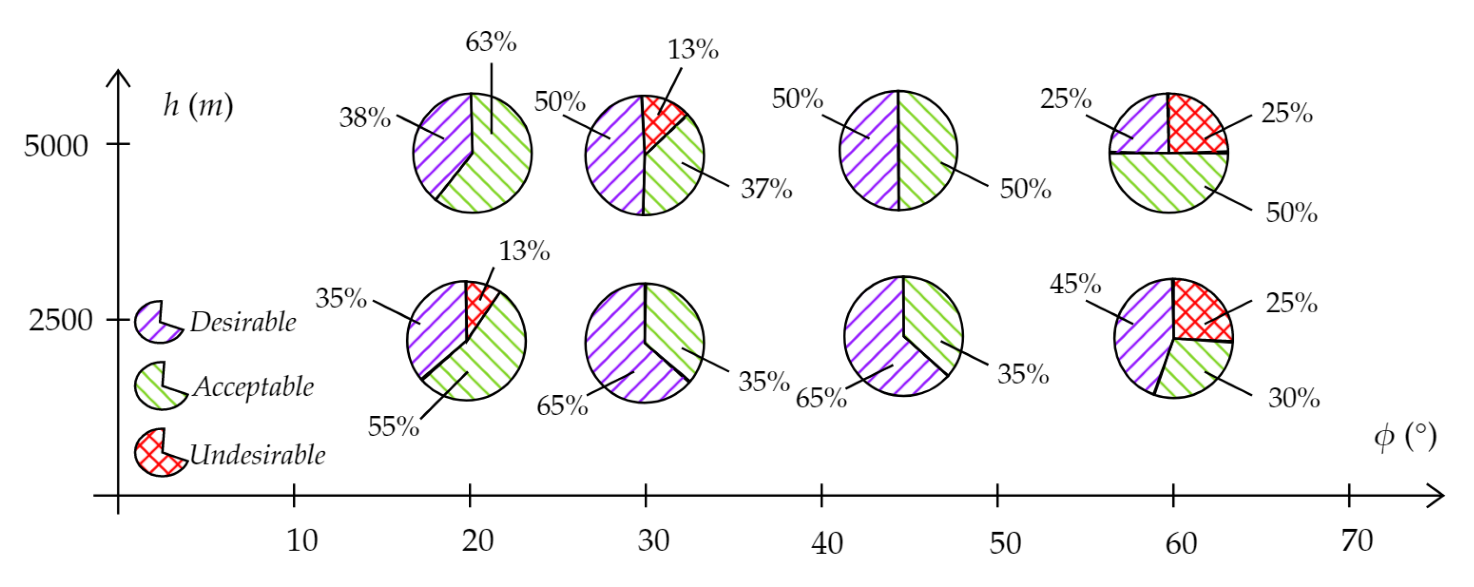
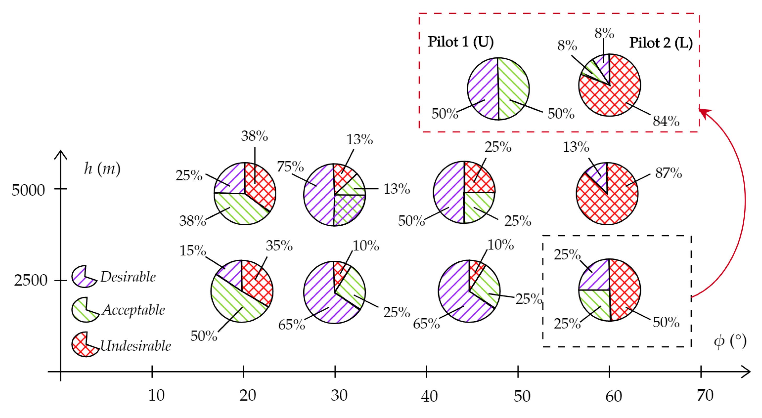
Processed qualitative results from the test runs are given in
Figure 9 and
Figure 10 for gate position and gate alignment rating criteria. In
Figure 9, proportions of desirable, acceptable and undesirable position performance ratings at the end of the steady turn are shown as a function of altitude and bank angle tested. Similarly,
Figure 10 shows alignment performance results. Feedback from both pilots are summarised below:
A clear rise in required input amplitude was highlighted with banking angle with low and subtle inputs for the lower spectrum of banking turns and full control authority on rudder and aileron in the higher banking turns.
Lower roll rates and bank angles linked to the banking turn were better controlled if initiated through rudder inputs and controlled through aileron.
A piece-wise or breakdown tendency of the steady turn when excessive roll was used for the banking turn. It was argued by pilots that a relatively low angle of bank was harder to maintain and track as they aligned the aircraft to environmental visual cues.
Maximum rudder was necessary to maintain altitude at and banking turns, though this was allowed in the manoeuvre.
Maintaining constant aircraft velocity is especially challenging during the manoeuvre due to the tight scheduling between the subsequent sections. This was especially true for the two subsequent turns. For lower banking angles, there was no difficulty in maintaining constant airspeed.
Undesirable performances at one of the manoeuvre section could effectively impact performances in the upcoming section, unless the pilot decided to “reset” his position and alignment by sacrificing said section. Effectively, the pilots’ second banking turn performances were nearly always degraded by undesirable first turn performances.
Higher altitude testing, at similar airspeeds, definitely led to variations in control authority and increased the stalling velocity shedding at higher banking turns. The lower dynamic pressure effectively led to worse performance, though less simulations were run in these conditions.
Overall best performances were achieved at the and banking turns, with little undesirable performances. Most undesirable performances at these sections arose from an excessive altitude at the end of the turn, which forced the pilot to nose down and sacrifice alignment rating to reach target position.
It is clear from these results that lower bank angle turns at led to relatively high percentages of undesirable and acceptable rather than desirable performances. As highlighted by the pilot feedback, this is mostly due to a piece-wise steady turn tendency from the pilots (which had already been suggested by the example seen in the previous section). Effectively, as the pilots tended to exceed the banking target and turned in too quickly in direction to the visual cue, a breakdown of the turn into two or more phases naturally appeared in order to realign the aircraft correctly, with sometimes drastic corrections near the end of the turn to ensure desirable position and alignment. On the other hand, the other extreme banking angle being tested showed similar lack of desirable and acceptable performances. At a target banking turn, the additional time for dynamic roll in the manoeuvre sizing was effectively minimal before with a manoeuvre on the edge of becoming infeasible. This led to a higher number of undesirable performances in both position and alignment, though a severe discrepancy was noticed between the two pilots involved in the testing. It could be argued that the first pilots’ better geometrical knowledge of the manoeuvre, simulator practice and greater simulation training time biased these results as the latter clearly performed better. Additionally, the first pilot started his rolling manoeuvre as soon as the gate was passed in order to reach the desired position and alignment. However, and most importantly, both pilots failed to maintain desired airspeed during the banking turns despite using maximum throttle authority especially at higher altitudes. The repetition of two turns led to too much velocity being shed during the turn with high kinetic energy and altitude losses ultimately leading to near stall conditions, deteriorated position and alignment upon reaching the checkpoints.
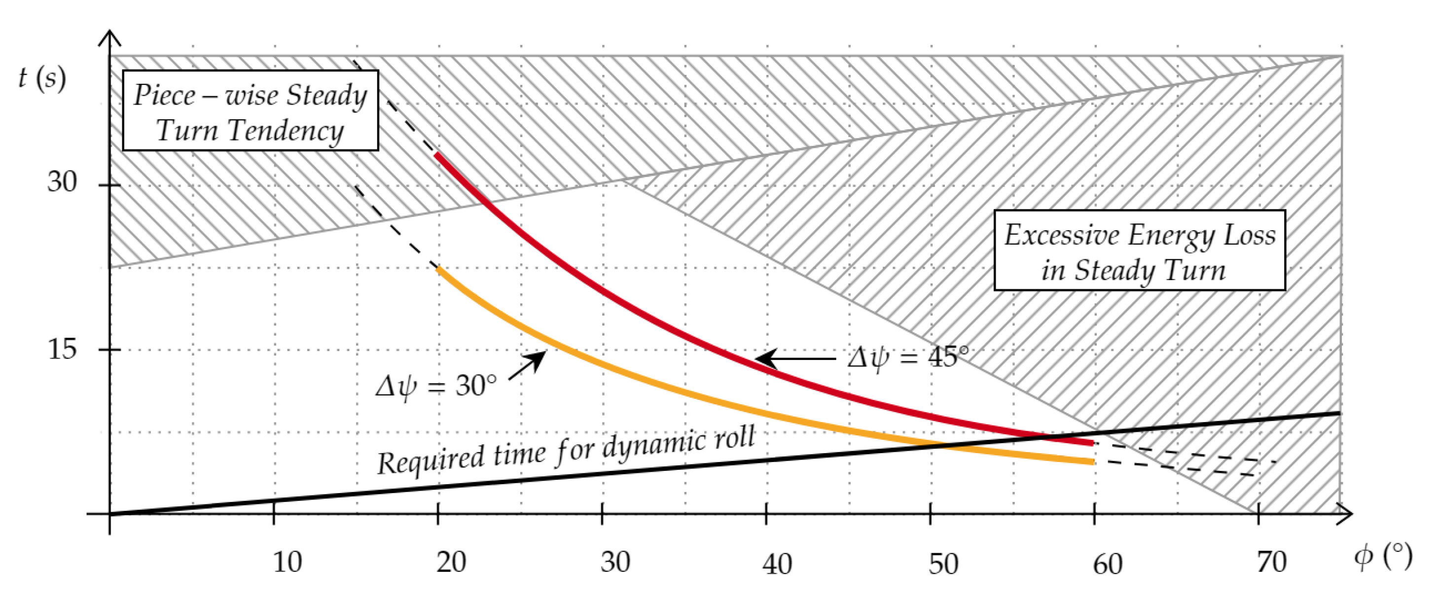
It was also found that turn time and heading change played a significant role in overall performance and manoeuvre applicability.
Figure 11 stands as a visual representation of the SLAT applicability range as a function of heading change and banking angle. The required times for two steady turn heading changes as a function of banking angle are given in the chart for illustrative purposes. As expected, longer turn times at high banking angles led to unsuitable simulation conditions with airspeeds impossible to maintain constant for the tested Boeing B747 aircraft model due to lack of thrust in a realistic model. Thus, an estimate of the unsuitable testing conditions due to unrealistic constant airspeed constraints is given in
Figure 11 which must be accounted for when considering the manoeuvre. Secondly, an estimate of the piece-wise turn tendency found to mainly arise with longer turns at lower banking angles is also given. Lastly, the estimates of the required additional time to reach the desired bank angle are given, which should therefore be added to the manoeuvre sizing method. It can be seen that, for the larger banking turns, the dynamic roll phase time (both ways) exceeds that of the steady phase.
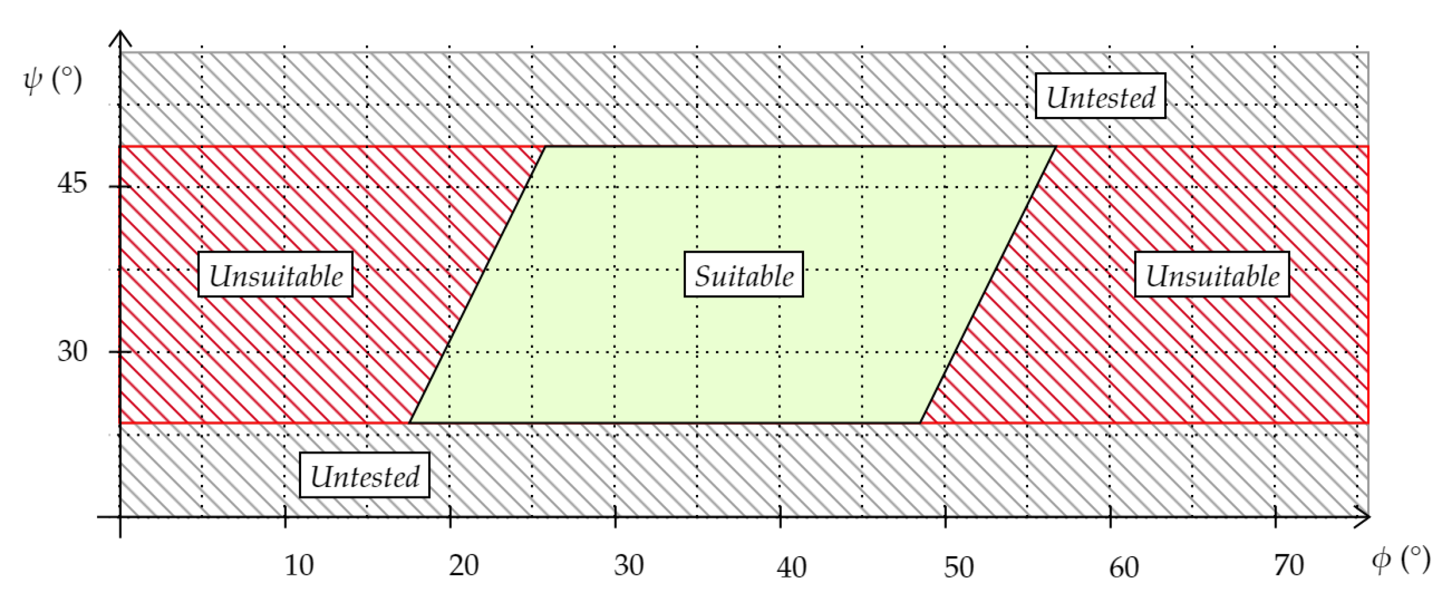
Based on the qualitative analysis of desirable, acceptable and undesirable performances presented above and validated by the quantitative recordings of the simulations,
Figure 12 highlights the manoeuvre suggested applicability range found by the author for a Boeing B747 aircraft model. Note that, in
Figure 12, the suitable domain for manoeuvre applicability is expected to be extendible to the left hand side (lower banking angles) by reducing the turn time or total heading change as it would decrease the demonstrated piece-wise linear tendency. On the other hand, an extension to the right is improbable as higher banking turns were shown to lead to high velocity shedding for which these large aircraft are unable to compensate during the manoeuvre, quickly leading to stall conditions. Furthermore, higher banking angles would be unrealistic if even of interest. Moreover, the alignment tracking time defined in the manoeuvre as time where the pilot must maintain fine alignment after the steady turn phase also greatly influences the performance cascading effect mentioned previously. Though not appropriately quantified, the author suggests times between approximately 10 s to 15 s for adequate manoeuvre definition. Higher values can be used to more efficiently eliminate the cascading/linking between each section but also simplifies the tracking task and brings the performance rating upward. On the other hand, shorter tracking times drastically increase performance cascading effects especially at higher banking angles as seen herein. Note that aircraft size, dynamics and controllability also plays a major role in the latter assessment: a single tracking time will most definitely not lead to similar performance degradation tendency with an F-16 and an Airbus A340 aircraft. Following this test, additional results from other simulation runs at different airspeeds and altitude with dynamic pressures between 8 kPa and 15 kPa, also including additional pilots, were added to further confirm the highlighted unsuitable and suitable areas shown in
Figure 12.
Overall, it was found that, despite having developed a sizing model theoretically suited for a wide range of altitude, banking turns, heading changes and airspeeds (and therefore dynamic pressure), the manoeuvre can only be efficiently used within a restricted applicability range for it to be feasible in a large civil transport aircraft. Restrictions on banking turns were identified due to realistic banking, heading changes and dynamic pressure limits. Note that the manoeuvre, even if outside the proposed applicability range, will still highlight potential undesirable multi-directional handling qualities. Excessive difficulty, however, could bias the pilot opinion regarding aircraft handling qualities.
5.3. Comparing Aircraft Model Performance
In the EFS500, the Boeing 747 does not include any flight control system and correspondence. The Airbus A340 model, on the other hand, was implemented with a restricted set of realistic Airbus flight control schemes. For lateral and roll motion, this includes, for instance, a bank angle maximum at , a “zero roll rate” for side stick neutral when banking below a threshold (with automatic roll back to when above) and a roll rate limit of = 15·s (corresponding to Airbus normal law). A slight increase in aileron authority compared to the Boeing 747 model is also present. Note that turn coordination through rudder is not present in the implemented control law. Hence, a coordinated turn requires use of a rudder input regardless of the model. Therefore, both models display noticeable differences specifically in roll response with bank angle and rate limitations which have been clearly outlined in roll capture manoeuvres and OLM in the simulator.
In this test, it was attempted to use the SLAT manoeuvre to outline and quantify such a difference between the two models, by comparing the performances of a single test pilot using both models with a single SLAT manoeuvre. An experienced retired RAF test pilot accepted to participate in order to verify the SLAT suitability and compare the aircraft models, as stated in
Table 5.
A single SLAT manoeuvre definition was flown twice by the test pilot for each of the Airbus A340 and Boeing B747 aircraft models from the EFS500 database. The SLAT manoeuvre used herein was comprised of four turns at banking and heading change. It was designed to be flown twice at an altitude of 16.5 kft (5000 m) at an airspeed of = 300 kts or = 200 m·s. Note that, as the pilot participated in the manoeuvre geometric definition, only a 5 min free flight acclimatisation program was flown with the Boeing B747 aircraft model at a comparable altitude and airspeed to the actual test. The pilot was briefed on manoeuvre turn count, required banking and heading changes as well as the purpose of the manoeuvre and data recording methods prior to the start of the simulation.
Live voice recording, post manoeuvre feedback and CHR led to a comparison of the aircraft handling qualities, emphasised on lateral motion. An extract of the transcript of a voice recording during the first run of the SLAT Boeing B747 simulation is included in
Appendix C. From the transcript, it is clear that the task allowed the pilot to highlight key handling characteristics of the Boeing B747 model. This includes a lack of Pilot Induced Oscillation (PIO) tendency, the absence of adverse yaw or noticeable excessive Dutch roll. The pilot highlighted a slightly poorer roll rate than expected for the aircraft model flown at this altitude and airspeed. Open-loop testing at the end of the manoeuvre allowed the pilot to quantify his assertions on the spot with conventional angle capture tests. The pilot also pointed out during the test that the model tested herein appeared to be underperforming in terms of roll rate when compared to personal aircraft flight test experiences.
A subsequent Airbus A340 model SLAT test led to similar conclusions regarding overall handling qualities of the aircraft, though better roll mode time constant and roll rates were quickly identified during the SLAT and quantified by the test pilot during the subsequent open-loop response testing at the end of the simulation run. Overall, the combined use of a SLAT manoeuvre and subsequent open-loop verifications led to a couple of CHR scaling results with differences in the Airbus A340 and Boeing B747 model handling qualities, having been highlighted in the EFS500. It could be argued that the findings of the subsequent open-loop tests (time to roll rate and roll subsidence modes) could have been highlighted by a quantitative analysis of the SLAT manoeuvre (though the quick and easy runs of the open-loop tests justifies their use in this case). Therefore, the manoeuvre was capable of highlighting differences in the two aircraft and allowed for a handling quality assessment on lateral-directional and longitudinal dynamics.
5.4. An Expansion to the Offset Landing Manoeuvre
The test pilot from the previous performance comparison was also tasked to conduct an Offset Landing Manoeuvre for the two aircraft models in both an aggressive and normal control behaviour. The pilot was tasked to formulate a similar assessment of the aircraft handling qualities. The main purpose of this back to back testing with the SLAT test was to discuss the advantages and drawbacks of the newly introduced manoeuvre over that of the more conventional OLM.
Overall, the SLAT usefulness as an expansion to the OLM was defended by the pilot as a result of these tests. A similar handling qualities assessment was made with both manoeuvres. The pilot having landed both aircraft models in the desirable or acceptable areas defined in the pre-testing briefing, the Airbus A340 model, with the previously described control laws and greater aileron effectiveness was judged with more adequate handling qualities than the Boeing B747 (effectively without any control law). A similar CHR rating was given to both models with both SLAT and OLM by the test pilot (both in Level 1 grades).
One major advantage highlighted by the pilot of the SLAT task over the OLM is its applicability to a wider test envelope. Successfully used at different altitudes and airspeeds, the SLAT can be used to assess the handling qualities of the aircraft over a wider range of conditions, whereas the OLM is restricted to the landing scenario with flaps and landing gear deployed. Furthermore, the SLAT introduces a similar dynamic to the aircraft, and therefore somewhat constitutes an expansion to higher altitude scenarios for the OLM and potentially benefits from the established advantages of the manoeuvre in handling qualities assessments.
On the other hand, the lack of ground proximity in the SLAT scenario introduced an expected decrease in engagement and sense of urgency from the pilot when compared against the OLM, though the visual cues played their buoying role well in forcing adequate control from the pilot to reach desirable performances (especially at the end of the turn phase and during alignment tracking).
5.5. In-Flight Folding Wingtips
The manoeuvre was also used in a testing campaign of a large civil aircraft with in-flight folding wingtips. The system identification procedure presented in past published work [
35,
36] led to the identification of the impact of the folded and loose or coasting wingtips on key aerodynamic derivatives. Following a modification to the EFS500 software and the engineering station, manual increments to
and
were implemented to mimic the shifts predicted using the simulation results of the CA
LM aeroservoelastic framework [
40,
41] for the AX-1 aircraft, similar to an Airbus A340. The baseline configuration and a single folded aircraft scenario (symmetric
upward fold of 10% wingspan wingtips) were then flown in both OLM and SLAT scenarios. The SLAT scenario used is once again the same as the one introduced previously in
Section 5.3.
Unsurprisingly, given the relatively small shifts in aerodynamic derivatives, very little changes on aircraft roll characteristics were introduced. A slightly higher roll rate and lower roll damping was noticed by the pilot (effect of lower roll damping aerodynamic derivative ) in the folded configuration. Both aircraft displayed desirable performances in the SLAT according to the position and alignment tracking ratings. Additionally, the OLM also confirmed these findings in near ground landing conditions.
It should be noted that changes to a limited number of aerodynamic derivatives were made in this test as a number of other parameters were neglected. Additional aerodynamic derivative shifts must be identified and implemented in the EFS500 to model more accurately folding wingtip aircraft flight dynamics.
5.6. HARW Flexible Aircraft Concept
Finally, the SLAT manoeuvre was used to assess the handling qualities of a highly flexible HARW aircraft concept during a couple of innovative concept development workshops. The pilots which were invited to participate are described in
Table 2 and
Table 3. During both workshops, a real-time hardware accelerated aeroservoelastic framework was used to model aircraft flexibility. As such, the EFS500 aircraft database and flight dynamics model are effectively replaced by the CA
LM [
27,
34,
40,
41] aeroservoelastic framework. As the latter does not include any ground interference, landing gear and flaps modelling, the OLM task could not be performed (which partially justified the development of the SLAT manoeuvre in the first place). As the SLAT implementation process takes place only in the EFS500 environmental display, the use of CA
LM models for flight dynamics did not have any impact on SLAT implementation, post processing and flight simulator hardware set-up.
During the first workshop, a 4 turn
banking and heading change SLAT manoeuvre, similar to the one used in
Section 5.3 was flown at multiple altitudes and airspeeds. During the bank angle acquisition and steady turn phases of the manoeuvre, the HARW aircraft concept was found to display highly undesirable pilot induced lateral oscillations, which both test and commercial test pilot instantly pointed out. Roll response showed undesirable overshoot against aileron control and delays, mainly identified as due to the high wing flexibility and change in structural deflection with dynamic roll and aileron deflection. Additionally, undesirable coupling between lateral and longitudinal motion was highlighted, which led to undesirable performances during the fine alignment tracking phases of the manoeuvre, regardless of the flight conditions at which the test was performed. Note that, even with a rigid structure, the aircraft displayed undesirable handling qualities, with excessively under damped longitudinal oscillations leading to a PIO tendency and excessive lateral-directional coupling. Pilot CHR were established and highlighted the unacceptable handling qualities of the non-augmented aircraft—major deficiencies were established with a CHR of 10. Thus, specifications for changes in aircraft design were communicated to dedicated workshop partnering teams for iterative upgrades. In practice, the manoeuvre was judged as unachievable due to poor aircraft handling qualities rather than manoeuvre sizing parameters and flight conditions.
A revised aircraft concept was then flown with a similar SLAT manoeuvre. Having a refined wing and engine position, the non-augmented handling qualities of the aircraft were found to be significantly different. However, roll overshoot and delays in lateral aileron control were once more highlighted during the steady turn phases. The excessive lateral-directional coupling also persisted, leading to a challenging tracking phase. Overall, the manoeuvre was achievable, though the tracking phase required excessive amounts of multi-directional control.
Thus, using a single SLAT manoeuvre, a number of undesirable handling qualities of a flexible HARW aircraft concept were demonstrated and accurately broken down, demonstrating the use of the manoeuvre in this last test case.
6. Conclusions
Following the highlight of the tools and methods used for pilot-in-the-loop flight simulation at Cranfield University, a multi-directional slalom and alignment tracking (SLAT) manoeuvre was presented and discussed herein. The development process and methodology used to size the manoeuvre were discussed and verified through multiple simulation campaigns, which relied on the use of the SLAT manoeuvre in different conditions, for different purposes and with different pilot profiles.
6.1. Summary of Findings
It was found that the theoretical sizing models proved adequate to generate feasible manoeuvres within an identified range of manoeuvre parameters. The manoeuvre also proved to be an effective method for highlighting desirable and undesirable aircraft handling qualities when flown by experienced pilots. With gross position and fine alignment tracking phases flown subsequently and repeated during the task, variations in pilot input gains were highlighted, with more relaxed behaviour displayed when initiating and maintaining the steady turn before switching to more aggressive corrections when entering the fine alignment phase at the end of the banking turn. Testing presented herein included a first attempt at establishing the manoeuvre applicability and feasibility range as a function of target banking turn and heading change for a large civil transport aircraft. An example of a comparison between two aircraft models handling qualities using the SLAT manoeuvre was also discussed, as well as a comparison of results with the OLM task. Additionally, two subsequent future concept aircraft tests also illustrated potential uses of the manoeuvre in handling qualities assessments.
Whilst the task was flown by multiple pilots with varying experience, not all with testing experience in training were capable of understanding and performing the task adequately after appropriate briefing and without extensive trial and training time. Pilots have reported that the task, though not necessarily easy to perform, was easy to understand and visualise. Pilots were also performing the task based on environmental cues, and transitioned easily from instrument to environmental references (to control banking and airspeed for instance), as desired. The pilots did outline that the alignment tracking phases required more aggressive inputs, especially when the position at the end of the turn was far from optimal, thus highlighting a performance collapse cascading effect. More competent and experienced test pilots did perform more extensive handling qualities analysis based on the method as expected, with comparable results to the OLM in the single example presented.
Hence, these initial tests and simulation campaigns led to the manoeuvre meeting the authors’ original expectations and initial objectives. Additionally, it helped establish the manoeuvre as a potentially valuable testing tool, for large civil transport aircraft handling qualities assessments at multiple points of the flight envelope. The authors also expect that it could be used with different aircraft types, as long as the simple scaling method presented herein is applied appropriately.
6.2. Discussion on Manoeuvre Advantages and Drawbacks
The physics based sizing of the manoeuvre provides a simple and scalable experimental set-up, making it a strong base and advantage for a standardised and unified quantitative and qualitative analysis tool. Unlike the OLM or sea level S-turns which use the runway as a reference for size and performance, the manoeuvre can be scaled in time and space by changing the roll angle or increasing the number of turns which can help highlight pilot behaviour impact on the performances. Changing checkpoint altitude is also a clear advantage as the manoeuvre can be used at multiple points of the flight envelope. Furthermore, the challenge behind manoeuvre implementation is mainly related to visual enhancement and display of the fixed checkpoints (relative to the earth axis) in the simulation environment. This is significantly simpler than implementing a leading target aircraft in a tracking or refuelling task (and subsequent physical consequences such as down wash effects, for instance). Furthermore, the tracking of a moving target would not necessarily constitute a similar mission task. The operational relevance of tracking a moving target, possibly mimicking formation flight or in-flight refuelling, can be questioned for a certain type of aircraft which is not the case for the SLAT manoeuvre.
The OLM similarity to real mission scenarios and positioning on the edge of operational conditions are the main reasons behind the value of pilot feedback and performance metrics during such tests. As a highly demanding manoeuvre, the multi-directional behaviours and manoeuvrability of the aircraft in a landing configuration (including pilot mindset) are highlighted, and undesirable behaviour or characteristics picked up during the offset manoeuvre can be easily extrapolated to real flight dynamics. Undoubtedly, the same can be said about the SLAT task which is similar to the OLM, and pilots who have flown the task have highlighted the operational pertinence of the SLAT. In fact, the SLAT can be considered as somewhat of an expansion to the OLM, being applicable to more flight conditions and keeping similarly demanding (and tunable) pilot inputs.
Whilst the manoeuvre proved efficient at demonstrating the existence or lack of undesirable aircraft dynamics, it can be argued that using a set of simpler and more conventional open-loop tests or simple conventional manoeuvres would have been equally efficient. After all, these were used during experimental testing as pilots tried their hands on the aircraft models. Previously discussed test transcripts of the flight test pilots clearly highlighted how these open loop tests were subsequently used to quantify aircraft dynamic behaviour. However, a similar conclusion was drawn regarding the OLM, yet the advantages and benefits of flying this task were repeatedly shown and demonstrated. In practice, the author believes these simple open-loop tests can be used as a complement to the SLAT manoeuvre at a variety of points within the flight envelope.
Disadvantages were also identified as some pilots noted that the steady turn stage could be challenging to perform at lower banking angles. Specifically, gross position performance (position at the end of the steady turn) highly influences the performances quantified in the alignment stages. If the aircraft is misaligned after the steady turn, the fine alignment tracking will require significant effort for realignment. The latter does not indicate undesirable handling qualities during a tracking task but inadequate aircraft position at the start of the alignment stage. This realignment having been compared to the offset tracking task, pilots were capable of reaching similar conclusions despite not meeting the visual markers, which indicates that the aircraft handling qualities were not biased due to task difficulty or inadequacy. If marker position used for the tracking sections was updated as a function of the aircraft position at the end of the turn, both tracking and alignment performance would be made independent (which could be undesirable). Additionally, whilst the use of checkpoints was adequate for gross position acquisition, it was argued to be far from optimal for the alignment tracking phase of the manoeuvre. The limitations of the EFS500 environmental display required spherical spatial markers to be used at this stage of research. However, more efficient displays could be considered, such as projected trajectory and performance HUD displays rather than markers in the earth axis.
Finally, the reader should note that the appearance of complex heads up displays (HUD) systems and augmented reality was at the core of the motivation to use environment checkpoints in the SLAT manoeuvre. In fact, development of augmented reality (AR) technology could give the opportunity of using similar checkpoint based manoeuvres in real flight testing conditions in the future.
6.3. Further Work
Following recommendations from the literature, only a few test pilots were invited to establish the maturity of the method [
6]. However, it should be argued that, given the relatively low number of test pilots which participated in the development of this method (a couple with an additional commercial pilot with test pilot training), more work should be done as to further consolidate these findings. Specifically, further establishment of the applicability and feasibility domains for multiple aircraft types as well as a comparison of handling qualities assessment made with SLAT and other conventional manoeuvres at comparable flight conditions is required. This should allow more accurate conclusions based on statistical analysis of results. It will also further outline the predicted advantages and drawbacks of the manoeuvre over existing ones.
From a geometric and visual implementation aspect, a refining of the methodology used to qualify the alignment and tracking performance should be investigated, as spherical markers currently used have shown limitations. Definition of marker size and position could be further investigated by comparing alternatives, including changing marker shape. Additional automatic and quick quantitative post processing methods are also currently being developed to help the handling qualities assessment with both pilot feedback and processed time histories on the spot. This includes automatic performance assessment at the checkpoints.
It is believed by the authors that further development the manoeuvre could eventually lead to a wider applicability of the SLAT. In the flight simulator presented herein, only visual and audio information and cues are given to the human pilot. Cockpit or seat motion, or even tactile feedback such as g-suits and g-seats used to mimic the effect of directional and rotational acceleration are non-existent however, and should be considered to increase the realism and pilot experience during simulation. It is well known that pilot perception is based on both their visual and vestibular sensors to capture motions and attitudes relative to their environment during flight. Moreover, lateral accelerations are extremely uncomfortable to the human pilot, with directional and rotational accelerations also playing a significant importance in the pilot’s capability to control the aircraft and therefore give an accurate aircraft handling qualities assessment [
5]. Testing in motion platform simulators or less conventional airborne variable stability aircraft simulations could therefore help validate further the handling qualities assessment made using the SLAT manoeuvre. Finally, and as discussed in the previous subsection, the use of augmented reality technology could help bring the SLAT manoeuvre to test flight campaigns. Though the development and certification of such a technological set-up in real flight experiments could be tedious, the authors do believe that the use of recently developed HUD and AR technologies in civil aircraft could be used to display external checkpoints and trajectories as done with most recent military and private jets.


