Abstract
In this study, the on-going research into the improvement of micro-gas turbine propulsion system performance and the suitability for its application as propulsion systems for small tactical UAVs (<600 kg) is investigated. The study is focused around the concept of converting existing micro turbojet engines into turbofans with the use of a continuously variable gearbox, thus maintaining a single spool configuration and relative design simplicity. This is an effort to reduce the initial engine development cost, whilst improving the propulsive performance. The BMT 120 KS micro turbojet engine is selected for the performance evaluation of the conversion process using the gas turbine performance software GasTurb13. The preliminary design of a matched low-pressure compressor (LPC) for the proposed engine is then performed using meanline calculation methods. According to the analysis that is carried out, an improvement in the converted micro gas turbine engine performance, in terms of thrust and specific fuel consumption is achieved. Furthermore, with the introduction of a CVT gearbox, the fan speed operation may be adjusted independently of the core, allowing an increased thrust generation or better fuel consumption. This therefore enables a wider gamut of operating conditions and enhances the performance and scope of the tactical UAV.
1. Introduction
Many of today’s Unmanned Air Vehicles (UAVs) are still propeller driven, intended for low speed and low endurance applications. The use of advanced gas turbine propulsion systems enables faster flight speeds with an increased efficiency, but they are only found in larger military medium-altitude long endurance (MALE) and high-altitude long endurance (HALE) UAVs. This architecture of UAV commonly utilises existing turbine engines leveraged from small light aircrafts to perform the role of command, control, communications, computers, intelligence, surveillance, and reconnaissance (C4ISR). As on-going operational requirements expand, there is a need for a smaller UAVs with increased mission profile capabilities in terms of speed and endurance.
Micro gas turbine engines (MTE), commonly classified under 1 kN thrust of different configurations such as turbojet, turboprop and turbofan, provide a potential solution to achieving this requirement. The turbojet is the most common configuration of MTE currently found, mostly due to the relative simplicity of manufacture for homebuilders and hobbyists. These systems provide the required thrust for high-speed UAV applications; however, like the larger architecture, the range is hindered by a relatively poor fuel consumption. This is noted in works by both [1] and [2] that propose the conversion of micro-turbojets into micro-turbofan engines, and whose on-going projects provide the foundation of this study.
The primary objective of this paper is to investigate the potential of improving the performance of existing micro turbojet gas turbine engines through a conversion into turbofans for applications in small tactical military UAVs for enhanced speed and endurance applications. However, the single biggest question that must be answered to validate the need to study methods of improving the performance of MTEs is: “Is there a requirement for small UAVs and their respective mission profiles to utilise the potential advantages that MTEs offer over current propulsion systems?” In order to accomplish this, an innovative concept of converting existing micro turbojets into turbofans to minimize the design time and cost is further explored. A suitable existing micro-turbojet engine is selected and evaluated using gas turbine performance software to study the advantages of a conversion to a turbofan. The preliminary design of the low-pressure compressor to be coupled to the existing turbojet is then performed to validate the gas turbine performance with CFD. The work conducted will also demonstrate the potential advantages of not designing a new engine from the beginning. To achieve these aims, the following objectives were set out:
- Market analysis for military UAV requirements to assist in the investigation of the feasibility of MTE propulsive methods for high speed, high endurance UAV applications and microturbine engines.
- Technology study of current micro gas turbine engines and down-selection of suitable turbojet MTEs to evaluate them for a turbofan conversion.
- Gas turbine engine performance study with the aid of GasTurb software to evaluate and analyse the performance improvements of the proposed converted turbofan
- Performing a preliminary aerodynamic design study for the low-pressure compressor to be coupled with the selected engine.
2. Methodology
2.1. Unmanned Air Vehicles
Unmanned air vehicles (UAVs) have been implemented in both military and civil applications for many years, and the usage has exponentially increased within the last 10 years. With the advent of faster microprocessors enabling a greater connectivity and better technologies to support the intelligent autonomous control of unmanned air vehicles, this trend is likely to continue for the foreseeable future.
Pivotal in the operation of these unmanned air systems is a reliable and certifiable propulsion system that must meet the requirements for both civil & military mission profiles and that must be sized for UAVs with take-off weights ranging from less than 150 kg to more than 600 kg. Currently, gas turbine systems for UAV propulsion are of greater interest for military applications, so as to gain a greater tactical advantage and critically assist with saving the lives of soldiers. However, it is envisioned that the commercial use of gas turbine-propelled UAVs will eventually eclipse military use with a more cost-effective, reliable and efficient system. Thus, we determined that, for this study, the focus would be given to the military applications of gas turbine propulsion systems for UAVs below the 1 kN requirement.
In the UK, the Military Aviation Authority (MAA) regulates the operation of both manned and unmanned militaries, as well as remotely piloted aircrafts through a series of regulatory articles. Table 1 shows the MAA classification categories together with their NATO equivalent, taken from [3]. It should be noted that in the UK the common taxonomy for the UAV classification applies to the commercial sector as well.

Table 1.
NATO and UK unmanned aircraft classification.
2.2. Micro Gas Turbine Engines
The thermodynamic operation of micro gas turbines of the same configuration (axial/radial) is in many respects similar to that of larger turbomachines. However, the design procedure for MTEs is not a simple as applying scaling procedures to larger existing turbomachinery components. There are a number of operational and practical issues that affect the overall efficiency of MTEs and present a significant engineering challenge. According to [4], the main issues are heat transfer, the Reynolds number and geometric constraints.
- A significantly larger heat transfer between the hot and cold components in micro turbomachinery, which is often negligible in larger turbomachinery. The high-temperature gradient that exists between the compressor and combustion chambers leads to additional losses in the compressor efficiency, unless a significant thermal insulation is applied between the components. In addition, this presents the issue of not being able to simply model the compressor as adiabatic during the design process, further increasing the technical challenge.
- The large difference in Reynolds number between the large and micro gas turbines. The low Reynolds number is a large limiting factor in the efficiency of the MTE’s compressor stage and overall efficiency. Below the critical Re number for a single stage axial compressor, the rapid increase of drag occurs due to the transition to a laminar boundary flow.
- The relative surface roughness (surface roughness compared to the overall area) of components in MTEs is higher, and as a consequence so are the skin friction losses. For a given Re number, the losses due to skin friction increase as the component size decreases.
- Geometric restrictions in the microturbine machinery from the manufacturing process and material properties.
The first use of micro gas turbine engines (MTEs) for UAV propulsion systems began with enthusiasts of aviation remote-controlled (RC) models; however, they are very rudimental in design and construction, typically utilizing salvaged components such as the compressor in automotive turbochargers. Modern developments have yielded a new concept of the MTE, which intends to leverage the advantages of the system for smaller applications. Whilst no official category yet exists for MTEs, in line with the works of K. Kadosh and B. Cukurel, for this paper a micro gas turbine engine for propulsion is defined as producing a thrust under 1 kN or 225 lbs. Currently, it is understood that whilst existing classes of gas turbine engines have shown great advancements in recent years, in terms of both efficiency and performance, the concept of MTEs remains relatively undeveloped.
It can be seen from Figure 1 that the selection of engines in this thrust category consists mainly of turbojets, with a distinct lack of turbofan engines (modified from [5]). This observation forms the fundamental premises of this report, micro turbojet engines offer a simple design for producing high levels of thrust, but they suffer from poor efficiency and therefore increased specific fuel consumption. If an efficient, affordable turbofan engine of similar dimensions is successfully designed, the application of micro gas turbines may be expanded into further applications that have not considered due to the poor efficiency of currently available turbojets.
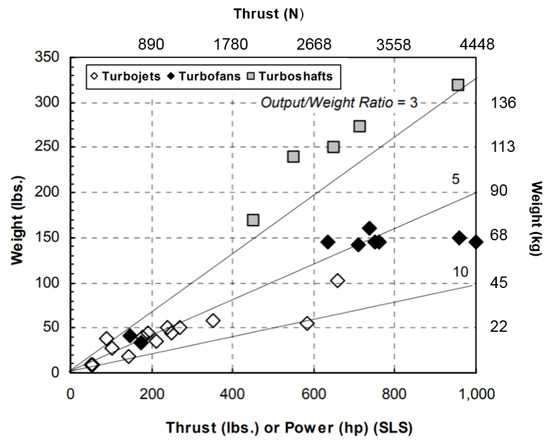
Figure 1.
Existing gas turbine engines under 1000 lbs of thrust.
2.3. Baseline Micro Turbojet Performance Study
To further study the performance of turbojet to turbofan MTE conversions, a well-established engine platform is selected as a baseline. Due to the growing interest, over recent years, in MTEs and commercial/military industries protecting investments, it is increasingly difficult to source reliable analytical and numerical data from engines. From an extensive review of literature from related projects, the BMT 120 KS (Figure 2) engine is found to be the most promising candidate as a baseline turbojet platform to study the potential performance increase with a conversion to a turbofan (modified from [6]). The improved performance of the BMT 120 KS engine has been substantially researched over the years, in particular at the Stellenbosch University’s Department of Mechanical and Mechatronic Engineering, with the data and findings publicly made available through numerous academic papers [7].

Figure 2.
(a) Image of BMT 120 KS micro jet engine [6]; and (b) Schematic of BMT 120 KS.
The performance characteristics of an engine can be analyzed under two conditions, the steady-state operation (equilibrium) or under transient operation. The scope of this study is under a steady-state operation, where the continuity of the mass flow and conservation of energy are satisfied. In addition, the engine performance is evaluated at the specified engine design point; the off-design engine operation is to be conducted in further works.
For this study, the design point of the converted engine is at the point where the BMT operates at peak efficiency. This is at a nominal speed of 120,000 RPM, with a thrust output of 130 N. The thermodynamic cycle analysis and preliminary design of the proposed micro-turbofan engine are carried out in GasTurb 13 software. The program allows for the calculation of the design and off-design performance parameters of the engine. With the use of parametric and optimization studies, the preliminary design of the turbofan conversion basic engine parameters and thermodynamic states may be determined.
Before the engine cycle analysis is discussed, here is a quick note on the GasTurb software mathematics and iteration algorithms. Much like other commercial gas turbine simulation software, GasTurb uses the matrix iteration method for convergence. This general iteration technique uses equal values of matching guesses and constraints, where guessed variables are continuously updated until the constraint parameters are satisfied. The iteration technique in GasTurb uses the multi-variable Newton-Raphson method to manipulate variables so that errors are insignificant. The system of linear equations is solved by means of the Gaussian elimination to generate the partial derivatives and find solutions. The process of the matrix iteration method is as follows:
- Estimate or matching guess of the initial inlet temperatures for the compressor and turbine
- Calculation or matching constraint of the turbine and nozzle operating points.
- Calculate the error between the matching constraints and guess.
- Adjust in the matching guesses and iterate.
- Combine the errors from the matching guess and constraints to form a matrix of partial derivatives.
- Invert the matrix and change all of the matching guesses by the amounts given by multiplying the inverted partial derivatives matrix by the error’s matrix.
- Repeat the procedure until the errors between the calculated values of the matching constraints and guesses converge.
The first step is to model the BMT 120 KS micro turbojet engine, which is intended to be the core stream of the converted turbofan configuration. The purpose of this step is to validate the GasTurb simulation against experimental data from [6] and [8], as seen in Table 2 and Table 3.

Table 2.
BMT 120 KS Experimental engine performance data, taken from [8].

Table 3.
Summarized experimental data for BMT 120 KS, taken from [6].
Figure 3 below shows the station numbering for the 120 KS turbojet engine; the thermodynamic states of the flow at each of the stations is calculated in the simulation. The specifications for the baseline BMT 120 KS are shown in Table 4.
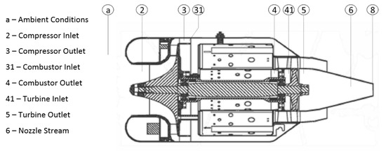
Figure 3.
Baseline engine schematic with station numbering.

Table 4.
GasTurb13 Input Parameters for BMT 120 KS Engine.
The mass flow rate through the compressor is known from the experimental data provided by [9], and Figure 4 and Figure 5 show the extrapolated pressure ratio and compressor efficiency data from the compressor map for the BMT 120 KS engine (modified from [10]). Note that the units of the corrected mass flow 101.325 kPa = 1.01325 bar; thus, for a relative mass flow through the compressor at :
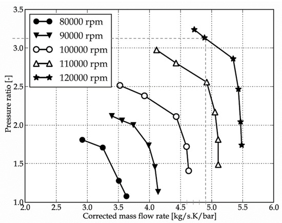
Figure 4.
BMT compressor map (Pressure ratio vs Corrected mass flow).
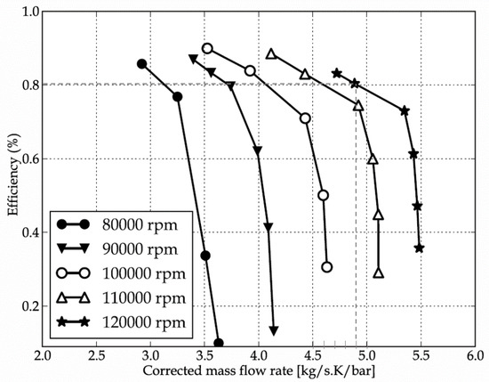
Figure 5.
BMT compressor map (Efficiency vs Corrected mass flow).
Figure A1 in Appendix A shows the input parameters for the baseline turbojet (BMT 120 KS) engine performance simulation results for the simulation may be found in Section 3 of this paper.
2.4. Micro Turbofan Conversion Performance Study
With the core stream parameters simulated in GasTurb successfully validated against the experimental data, the cycle analysis of the converted turbojet to turbofan is carried out. It should be noted that some challenges and limitations in the software were encountered, which may affect the accuracy of the simulation. The software is used for the simulation of most common types of aircraft and power generation gas turbines; however, the unique configuration that is to be modelled is not included. The limitations of the software do not allow for new configurations of engines to be defined. A single spool turboshaft with an attached load fan is modelled, but it does not account for the thrust generation from the bypass stream. The most suitable results are obtained from a single spool mixed turbofan engine configuration, where the CVT gearbox is accounted for via mechanical losses and the associated reduction in mechanical efficiency. The evaluation of variable gear ratios is obtained from multiple simulations.
2.4.1. Simulation Input Parameters
Figure 6 below shows the station locations used for the engine performance simulation of a turbofan engine (modified from [6]).
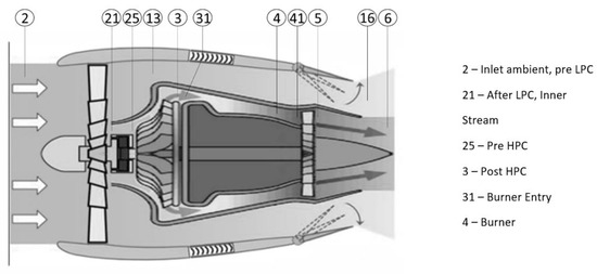
Figure 6.
The converted turbofan engine schematic with the associated station numbering.
During the conversion to a turbofan, the BMT 120 KS becomes the core of the engine; thus, the known parameters for the validated baseline turbojet are transferred into the engine model. In a similar manner to the baseline turbojet, the engine parameters are specified in the software. Figure A2 in Appendix A shows the finalized input parameters at a nominal fan speed of 30,492 RPM (after a comprehensive iteration) used for the engine model.
2.4.2. Intake Pressure Ratio
In GasTurb, many of the parameters may be specified in several ways, which allows for flexibility in unknown parameters. For instance, the intake pressure ratio can be specified, as any positive number is directly used as P2/P0 with the exception of the value 2, which selects the intake map option. However, no intake maps are currently available for the micro gas turbines; moreover, considering the relative size and geometry, the inlet compression is likely minimal, and therefore a total inlet pressure recovery is assumed; thus, the intake pressure ratio is set to 1.
2.4.3. Core Stream/Bypass Stream Losses
For the turbofan engines, a radial pressure profile at the engine face may be modelled. For the property (No (0) or Average (1) Core dP/P). For this simulation, the value 0.99 is the input, implying a negligible pressure loss difference in both the core and the bypass stream.
2.4.4. LPC Pressure Ratio
Fan intake maps for this application are not widely available. The use of a similarity analysis and Buckingham P theorem to scale down the fan intake map from NASA’s publicly available “Experimental Quiet Engine Program” was used [11]. The scaled fan map from the results Fan A in the NASA publication seen in Figure 7 is used to determine the design point of the LPC for this study (modified from [1]).
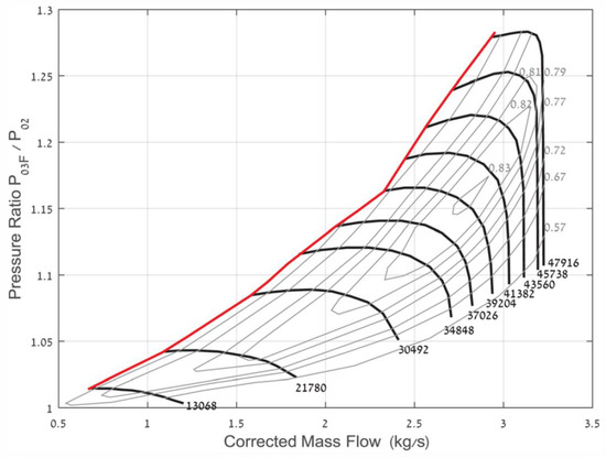
Figure 7.
Scaled LPC fan performance map.
The fan operation is studied at varying points along the performance curve in the figure above. Note that the compressor is considered fully subsonic and that the inlet Mach number is assumed at a maximum 0.5 to prevent damage to LPC. The mass flow, pressure ratio and efficiency are read along the speed line for each of the compressor speeds. These values are then simulated to assess the LPC performance. The study is also conducted at varying compressor speeds. This is a representative study of the varying gear ratios of the coupled LPC. As mentioned, only the on-design operation is simulated in the model. For each of the corresponding speed lines, the associated corrected flow, pressure ratio and low-pressure compressor efficiencies are input to the engine model. The mechanical losses associated with the gearbox are also modelled via an increasing reduction in mechanical efficiency with a reduction in the fan speed. As this engine model and simulation are only for the design point, the operating conditions of the core compressor and turbine performance maps are fixed at W25Rstd 0.293 kg/s with P25/P3 = 3.15, and thus the results are not affected by the single spool operating at the chosen nominal speed. As mentioned in previous sections, [2] states that a practical limit of the maximum core to bypass the pressure ratio difference should not exceed a certain limit due to the increased axial velocity at the rotor hub and therefore the associated loading issues. It was found that at higher speeds the difference between the core and bypass pressure ratios exceeds acceptable limits and results in unrealistic results. In addition, it is found that for the LPC, using the scaled performance map the maximum achievable speed is 30,432. This is due to the compressor reaching the upper mass flow rate/pressure ratio achievable for the stage and results in the core nozzle velocity dropping to unrealistic values.
2.4.5. Duct Pressure Ratios
The data is unavailable for the duct pressure ratios in micro gas turbine applications. For the preliminary design, the pressure loss in flow ducts such as the bypass duct and turbine exit duct are assumed to be minimal and are thus represented as 0.99.
2.4.6. Design Bypass Ratio
The BPR is calculated during the iteration process of the simulation. The corrected mass flow inlet to the high-pressure compressor is fixed and specified at W25Rstd = 0.293. The fan mass flow or total inlet flow W2Rstd is varied during the cycle analysis, determined from the fan map in Figure 7. BPR = m_dot fan/m_dot core. With the pressure ratio across the LPC and efficiency also read from the performance curve, the only remaining variable is the bypass ratio, which is iterated to satisfy the independent variables.
2.4.7. Combustor Properties
The input parameters for the burner are fixed to the validated values from the BMT 120 KS turbojet engine simulation.
2.4.8. Stream Mixing Parameters
The inputs for the hot and cold stream pressure ratio are set to 1 and not considered for the engine cycle analysis.
2.4.9. Design Mach Numbers
For the calculation of the thermodynamic cycle of the engine, the flow properties, such as the total pressure and temperature at the component boundaries, are only required. With the inclusion of the appropriate design Mach numbers at the component boundaries, the aero-thermodynamic important dimensions and geometry are defined. In the case of this study, the dimensions of the core of the engine (turbojet to be modified) are known, and therefore the definition of the design Mach numbers is not required for all but the low-pressure compressor.
2.4.10. Secondary Air System
Similar to the baseline engine simulation, most secondary air systems are not defined for the engine performance system. Only the number of turbine stages is defined at 1.
2.5. Low Pressure Compressor Preliminary Aerodynamic Design—Procedure
This section covers the procedure used to form the preliminary design of the low-pressure compressor to be matched with the BMT 120 KS micro turbojet as part of the conversion into a micro-turbofan. The performance parameters of the LPC, determined in the previous section, are carried over to the preliminary design. There are multiple design methods that may be applied in the field of turbomachinery. As the preliminary design of the low-pressure compressor (LPC) is not the sole topic of this paper, ANSYS turbomachinery design tools are utilized to make the iterative process of the design more efficient. The advantage in this is that the design specifications and basic parameters determined from the engine performance section can be directly used to produce a preliminary design, rather than the more historic method of starting with an existing machine flow path and geometry (which in this case would be difficult to acquire). The three basic steps for the design of the LPC are as follows (reference Figure 8):
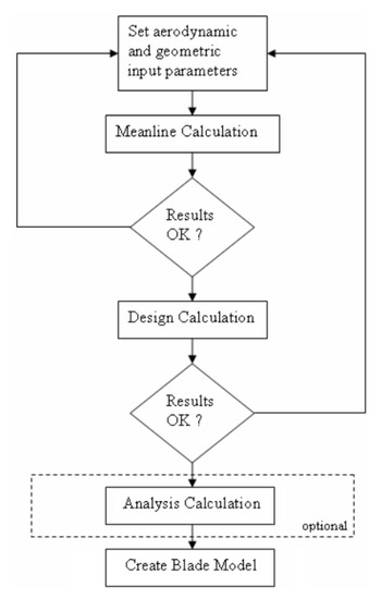
Figure 8.
Flow chart of the LPC aerodynamic design procedure.
- The design calculation scheme starts a one-dimensional hypothesis of the mean streamline or so-called “mean-line design”. An analysis of this stage provides estimations of the overall performance and efficiency of the LPC. The initial estimates of the 1D aerodynamic dependent parameters are computed.
- The next phase leads to the specification of the two-dimensional streamline. With the addition of the blade geometry and by computing the blade as a succession of several cascades, the two-dimensional nature of the flow is evaluated.
- Finally, the blade profile is fully resolved by implementing a three-dimensional analysis with computational fluid dynamics.
A preliminary aerodynamic design of the system is conducted using a meanline flow through analysis. Vista, an ANSYS turbomachinery design tool extension by PCA Engineers Ltd. is used to assist with the design process. The meanline flow-through design method is based on the conservation laws (mass, momentum and energy) upon which the basic flow physics are calculated along the critical streamline of the compressor. For the preliminary design of the LPC, the evaluation of key performance parameters, such as the DeHaller number, pressure rise coefficient, loading and diffusion factor, are required at the meanline and the hub.
3. Results and Discussion
3.1. Baseline Micro Turbojet Simulation Results and Discussion
The simulation uses the boundary conditions input data, such as the rotational speed, compressor inlet mass flow rate, inlet pressure and temperature, the combustor outlet temperature and the turbine efficiency (as specified in the previous section), and it applies the matrix iteration component matching method to compute the engine performance parameters. The system fuel flow rate and the turbine mass flow rate are then determined based on the combustor outlet temperature, fuel heating value and the compressor mass flow rate. The simulation of the baseline GasTurb turbojet model is performed at the altitude engine test facility with ISA ambient conditions at 0 m altitude; the results may be seen in Figure A3 in Appendix A.
From the results, a good agreement is achieved between the simulated results in GasTurb and the experimental data available from [6] for a spool speed of 120,000 RPM. A thrust of 130 N is simulated in comparison to the recorded experimental value of 136.6 N. Additionally, the simulated fuel mass flow is 0.00472 kg/s, compared to 0.0063 kg. The variations in the values may be attributed to the ambient conditions at the test facility during the experimental testing, as well as to additional frictional losses in the bearing and lubrication. Below, Figure 9 shows the thermodynamic states of the cycle and is used to further analyse the validity of the simulation. The clear addition of mf to ma may be seen at station 3 as part of the combustion process; it then remains constant after exiting the burner. The variations in total temperature and pressure align with expectations of thermodynamic states through compression, combustion and expansion, whilst the static pressure changes throughout the cycle.
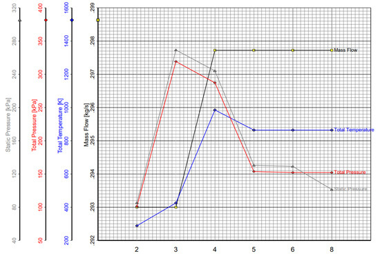
Figure 9.
Station properties for the baseline turbojet simulation at 0.13 kN.
3.2. Micro Turbofan Conversion Results and Discussion
The GasTurb engine performance results for the converted turbofan cycle analysis are shown in the summary in Appendix A. Figure 10, below, illustrates the final results after a significant iteration for the design point of the converted turbofan. A thermodynamic analysis of the engine cycle yields that the engine achieves a thrust value of 180 N with a TSFC of 36.4814 g/kNs. This performance is at an engine core nominal design speed of 120 kRPM, fan speed of 30 kRPM, with total mass flow rate of 2.02 kg/s at a bypass ratio of 5.54. For the fan speed of 30,432 RPM the finalized value for the LPC inner pressure rise is 1.08 at an efficiency of 0.815, and for the LPC outer pressure rise it is 1.075 at an efficiency of 0.81.
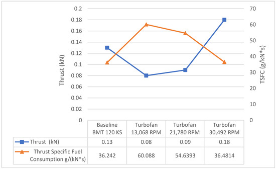
Figure 10.
Comparison of the baseline turbojet simulated results to the converted turbofan at variable gear ratios.
Figure 10 displays the results for the investigation into varying gear ratios for the low-pressure compressor of the converted turbofan in comparison to the original baseline micro turbojet. The results highlight the potential advantage of a variable gear ratio coupled LPC to the original micro turbojet, and the flexibility to adjust the LPC performance for operational flight requirements. The additional input and output parameters for the varying spool speed simulations may be seen in Appendix A; the procedure that is followed is the same as the one described throughout this paper. As expected, the fan operation, at close to the maximum spool speed with an increased efficiency, higher mass and increased total pressure rise, yields significantly higher thrust values of 180 N > 130 N, a 38.46% increase. Conversely, the efficiency fan speed operation at 13,068 RPM yields a significant increase in TSFC of 60 g/(kN*s) > 36 g/(kN*s), a 65.8% increase.
3.3. Low Pressure Compressor Preliminary Aerodynamic Design
3.3.1. One Dimensional Meanline Calculation
The LPC design point for the varying speeds was identified through the iteration of performance values taken from a scaled fan map and simulated with the GasTurb engine performance software. The first step of the design procedure is to make the appropriate assumptions and calculations for the LPC efficiency, tip speed, axial velocity and related parameters. First, a constraint of the fan tip relative Mach number ≤ 1 (LPC tip speed = 330 m/s) is imposed, thereby avoiding associated wave drag from the supersonic flow. The inlet Mach number is fixed at 0.5 (≈160 m/s) for the design point of cruise conditions. The design parameters already identified from the engine simulation are as follows:
Next, the overall annulus dimensions, inlet and outlet of the compressor (hub-to-tip ratio—rh = hub radius, rt = tip radius) are sized (see Figure 11):
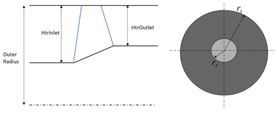
Figure 11.
Diagram explaining the geometry input parameters.
From the lessons learned in [2], no IGV is employed, as it is assumed in the design of this LPC that similar drops in efficiency can be expected due blading and increased shock losses. Therefore, no whirl velocity component is assumed in the calculation. From the isentropic flow equations: (Cp = 1.005 KJ/kg, R = 287 J/kg):
From the continuity equation:
The tip speed, tip radius and nominal spool speed are related by:
Thus, with the use of a simple spreadsheet and the above equations, the tip radius and spool speed can be evaluated over a range of different hub to tip ratios. The purpose of the evaluation is to iterate the variables of the hub-tip ratio and blade tip speed, in order to reach a target nominal speed as close to 30,492 RPM as possible, thus keeping the design parameters close to the results from the engine simulation.
Table 5 presents the results of the study. The initial selection of the tip speed at 330 m/s is chosen as an upper limit, and in order to reach a satisfactory solution the tip speed is reduced to 225 m/s. At a hub-tip ratio of 0.51, the speed is equal to 30,498 RPM, which is sufficient to match the required parameters. The hub to tip ratio of 0.51 is selected as an arbitrary starting point, and the study is conducted from 0.4–0.6. A high hub-tip ratio results in an increased annulus diameter and increases the overall weight of the system; it may be seen that the blades would be approximately 70 mm for an annulus dimension of 150 mm. Conversely, a practical limit of the blade size must be realized, and an overly small hub-tip ratio results in a blade of around 66 mm. The hub-tip ratio will be later studied and adjusted in more detail through a numerical analysis. The relative Mach number at the rotor tip is calculated in order to validate the results. From the velocity triangle:

Table 5.
Variations of the hub-tip ratio with the spool speed.
Therefore, an acceptable subsonic relative Mach number at the rotor tip of 0.83 is calculated. The LPC inlet parameters are validated using the GasTurb software. For the chosen design point along the 30,492 RPM speed line, the LPC design parameters are input. The iteration variables, such as the LPC inlet radius ratio, design bypass ratio and LPC outer pressure ratio, are set, and the target design spool speed is set as the studied fan map speed line. Upon simulation, GasTurb iterates between variables and converges on an acceptable solution with independent variables, LPC Inlet Radius Ratio and Design Spool Speed, which are the criteria for the fan preliminary design. Figure A5 in Appendix A summarises the results for the LPC preliminary design reached after numerous iterations. A design spool speed of 30,494 RPM is achieved, which matches the scaled performance curve by an acceptable degree for this stage. At this spool speed, a minimum 4:1 reduction gearbox is required to separate the fan from the core spool speed of 120,000 RPM. It may also be seen that the LPC diameter is calculated at 140 mm, which, considering the 110 mm inlet of the BMT 120 KS, is an acceptable solution for a low bypass solution.
The aerodynamic inlet operating conditions determined previously are used as the initial design parameters in the meanline analysis, as seen below in Table 6. The total pressure rises through the rotor after any downstream pressure losses, neglecting the swirl component. Downstream mixing losses specifies the proportion of axial dynamic pressure at the rotor exit that is assumed to be lost due to the aerodynamic mixing process, which, left as the default value of 25%, offers a robust solution. The hub velocity deficit factor is used to adjust the meanline calculation to take into account the influence of the boundary layer at the hub.

Table 6.
Aerodynamic input for the meanline calculation.
With the aerodynamic inputs defined, for one dimensional meanline calculations the remaining parameters affecting the results are the outer diameter, hub/tip ratio inlet and hub/tip outlet (see Figure 11). The initial LPC annulus/rotor geometries, calculated from the GasTurb engine model simulation, are used as the starting point for the flow through analysis of the geometry inputs. The inlet tip diameter, calculated at 0.14092 m, provides a first good estimate for the annulus outer dimensions. At a hub-tip ratio of 0.53, the resulting blade height estimate is 66.27 mm; thus, the tip clearance is 4.19 mm or s/h = 0.05, which for this stage is sufficient. The clearance has a strong effect on the efficiency, but it is not modelled in the meanline calculation and will be taken into consideration at a later design phase.
The evaluation of the initial meanline calculation results for an annulus outer diameter of 0.141 m and hub-tip ratio of 0.53 produces unsatisfactory results. It is found that the hub is overly loaded with the minimum stage loading calculated at 0.95 for a hub-tip ratio equal to 0.53, in addition to the flow coefficient exceeding the <0.8 criterion for both the meanline and hub. The study is expanded to allow for slight modification of the annulus dimensions, and the considerations include the fact that an outer diameter that is too large for the duty will suffer from increased swirl and associated pressure losses. Equally, a diameter that is too small will lead to higher loadings and a reduced DeHaller (DH) number (where a light aerodynamic loading is the key here, i.e., a low rate of diffusion with DH = W2/W1 > 0.72).
To achieve acceptable solutions for the meanline calculation, the annulus outer diameter must be increased. From further sizing of the LPC inlet and with reference to Table 5, it is calculated that the maximum obtainable annulus size, limited by the relative tip Mach number, whilst maintaining the initial input aerodynamic parameters (mass flow/spool speed/pressure ratio), is 0.17 m; this is validated in GasTurb, and the results are summarized in Figure A6 in Appendix A.
Different values for the annulus diameter, up to 0.17 m, are analyzed. Figure 12, Figure 13 and Figure 14 shows the graphical results of the meanline calculation for the study of the annulus outer diameter. The design point is associated with the hub-tip inlet, which is varied at +0.01 from 0.4–0.6 for the study.
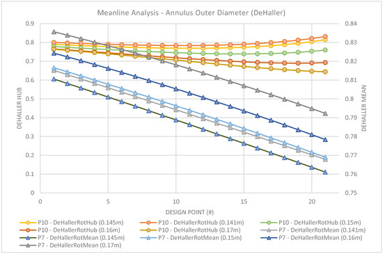
Figure 12.
Meanline analysis for the outer diameter (DeHaller number).
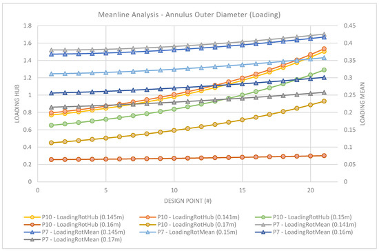
Figure 13.
Meanline analysis for the annulus outer diameter (loading).
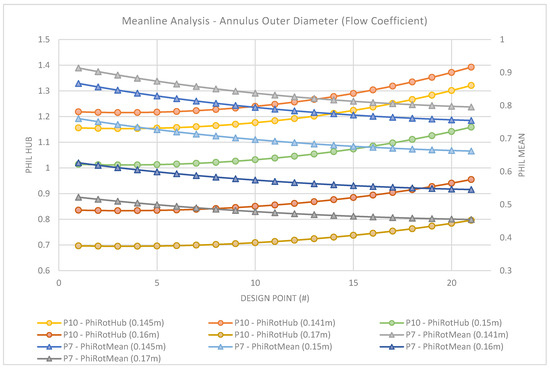
Figure 14.
Meanline analysis—annulus outer diameter (flow coefficient).
Studying Figure 12, Figure 13 and Figure 14, it may be seen that the meanline and hub for all annulus diameters satisfies the criteria of DeHaller >0.72. Additonally, a smaller annulus diameter produces more favorable results in terms of the meanline DeHaller, especially approaching higher hub-tip ratios of more than 0.55 (DP 15). However, as a consequence, the hub becomes highly loaded, which significantly impacts the efficiency. Moreover, from the evaluation of the loading coefficient (ψ), it is apparent that for all annulus dimensions but 0.17 m, a suitable design would not be achievable as hub ψ exceeds 1. Finally, the flow coefficient, which is given by the axial velocity over the rotational speed of the rotor, is thus dependent only on the inlet hub to tip ratio. An acceptable solution for the flow coefficient should be below 0.8, which again leaves the 0.17 outer diameter as the more suitable value.
With the outer annulus diameter determined, the hub/tip ratio input and output parameters are then varied during an iteration study to determine the optimum values for the 1D meanline analysis (Table 7). It is advantageous to increase the outer hub/tip over the inlet in order to accelerate the axial flow, increasing the overall pressure rise of the stage and assisting in the prevention of stall. For the first set of data, the hub/tip inlet and outlet values are constant (i.e., HtrInlet = 0.53 and HtrOutlet = 0.53). After the baseline evaluation is complete, the values are iterated at +0.01 intervals from 0.4–0.6 to estimate the performance for given aerodynamic and geometric input parameters. A table displaying the meanline analysis iteration process may be seen below.

Table 7.
Iteration procedure for the meanline analysis of the annulus outer diameter 0.17 m.
Figure 15, Figure 16 and Figure 17 present the results of the study for evaluating the hub to tip ratio for the rotor at an annulus outer diameter of 0.17 m. In this study, the objective is to find the optimum annulus geometry and size before further studying and optimization is conducted with a through-flow calculation.
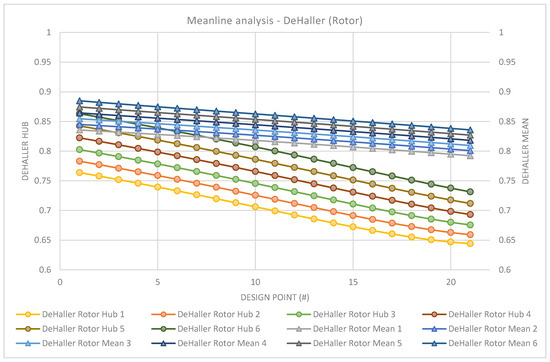
Figure 15.
Meanline analysis—DeHaller number (Rotor).
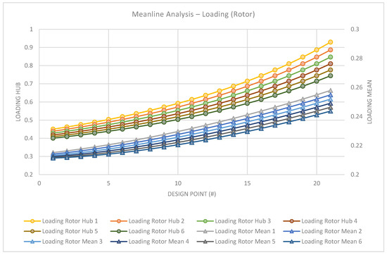
Figure 16.
Meanline analysis—loading (rotor).
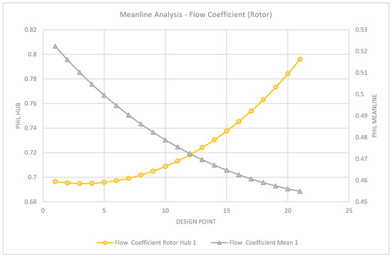
Figure 17.
Meanline analysis—flow coefficient.
Figure 15 shows the meanline flow analysis DeHaller number results graphically. The graph is used in conjunction with numerical data to determine the geometry for producing preferable results in terms of the DeHaller number (ratio of relative velocities, W2/W1 > 0.72). It is clearly observed that increasing the hub-tip ratio at the outlet over the inlet increases the axial velocity: for example, design point 6 (HtrInlet 0.54, HtrOutlet 0.54) with hub DeHaller 0.72 and meanline 0.82, compared to the last iteration (HtrInlet 0.54, HtrOutlet 0.59) with an equivalent hub DeHaller 0.82 and meanline 0.86. The iterations 1 to 3 for the design points 1 to 10 proved to be geometries with a preferable hub DeHaller; the meanline DeHaller remains high for all of the evaluated geometries, indicating light aerodynamic loading, i.e., a low rate of diffusion. The loading coefficient for the study is seen in Figure 16. As stated in the background section, studies show that the peak efficiency of the compressors peaks around a loading coefficient of 0.35–0.42. From the evaluation of the loading coefficient, the design points 1–10 present geometries with a slightly increased aerodynamic loading for a peak efficiency with a low loaded meanline. Increasing the hub-tip ratio above 0.5 results in an excessively loaded hub. Figure 17 shows the flow coefficient for the meanline calculation, where all design points meet the criteria of <0.8. The hub flow coefficient is preferable in the region of design points 1–12.
3.3.2. Meanline Calculation Summary
The preliminary meanline calculation of the LPC design is conducted in this section, where an iterative study is conducted for the independent variables of the hub to tip inlet and outlet. From the results, it is determined that the iterations 1 and 2 for the design points 0–10 produce sets of geometry that are satisfactory and meet the performance criteria that are to be carried forward into a 2D through-flow analysis. Table 8 and Table 9 show the performance of two better performing geometry configurations that are to be analyzed further. At this stage, the estimates of rotor adiabatic efficiencies (taken as the efficiency estimate in the meanline calculation) are around 85%. All of the performance results yield a satisfactory value, i.e., the flow coefficient is <0.8, DeHaller number >0.72, and loading (which is case dependent on the DeHaller) <0.5 for higher efficiencies. The initial results show that the rotor is more highly loaded at the hub and more lightly loaded at the tip. The results are influenced by the hub loading parameter from the aerodynamic inputs and may be adjusted to redistribute the workload and thus reduce the loading at the hub of the rotor whilst maintaining the overall pressure rise. However, for the micro gas turbine machinery, it is expected that the hub is more highly loaded due to the increased max flux that concentrates around the hub. In addition, the relative low hub/tip ratios commonly lead to higher hub loadings; at a fixed outer diameter of 0.17 m, the range of selected hub/tip ratios yield a vane chord height of just ≈5 cm.

Table 8.
Results from the 1D meanline analysis for the design point 4, iteration 1.

Table 9.
Results from the 1D meanline analysis for the design point 4, iteration 2.
3.3.3. Two-Dimensional Streamline Through-Flow Analysis
With satisfactory results from the meanline calculation for a selection of hub tip ratios, the performance study is expanded to include additional aerodynamic dependent input/output parameters. The additional input parameters include the rotor vane aspect ratio, number of vanes and profile trim. The aspect ratio is defined as the blade height/hub chord. From the works of [2] and individual experimentation yielding unacceptable results, it is found that for this application common aspect ratios of 3 to 5 cannot be achieved. Thus, the vanes are restricted to aspect ratios around unity, with wide streamwise hub chords ensuring a reasonable thickness to maximise the low Reynolds numbers in micro turbomachinery. The profile trim is defined as the chord at the tip chord/hub chord; for the rotor, this value is commonly <1, reducing the chord with as the span increases. In a similar procedure to the meanline calculation, a set of iteration parameters (as seen below) are defined, and the variables are iterated for different values. The design points and iterative setup may be seen in Table 10 and Table 11 as well as in Figure A7 and Figure A8 in Appendix A. The results of this study are summarised in Appendix A (Figure A9 and Figure A10).

Table 10.
Design points for the through-flow analysis.

Table 11.
Iteration procedure for the through-flow analysis.
The figures from Figure 18, Figure 19 and Figure 20 present the results of the 2D streamline through-flow study for variations in the rotor blade parameters. The iteration study (see Table 11) is performed for varying rotor blade parameters; note that a blade aspect ratio greater than 1.2 produces failed results, and in addition the blades acquire unsuitable dimensions for manufacture. As with the 1D analysis, the rotor loading at the hub increases as the hub-tip ratio decreases (Figure 18), i.e., for a fixed annulus the hub dimensions are reduced and thus become more loaded with an increased mass flux. The slight increase in the hub-tip outlet ratio also follows the same trend of reducing the hub loading. The meanline loading in both cases remains light. Similarly, the DeHaller number follows the same trend as with the 1D analysis (Figure 19), whereby W2/W1 expectedly decreases with the reduced hub-tip ratio. The diffusion factor describes the tendencies for the boundary layer to separate under the influence of the pressure rise in the blade passage and is a good indicator for the blade spacing or pitch to chord ratio s/c. For a high efficiency, an upper limit of 0.6 for the hub and 0.4–0.45 for the meanline is applied; above 0.5, the associated blading losses rise exponentially. From Figure 20, it is clearly seen that designs with an increased trailing edge blade pitch (s), i.e., with fewer blades, have higher diffusion factors and thus increased blade losses. At the calculated diffusion factors, however, the increased losses are potentially negligible against the benefits of a reduced weight and complexity of the design.
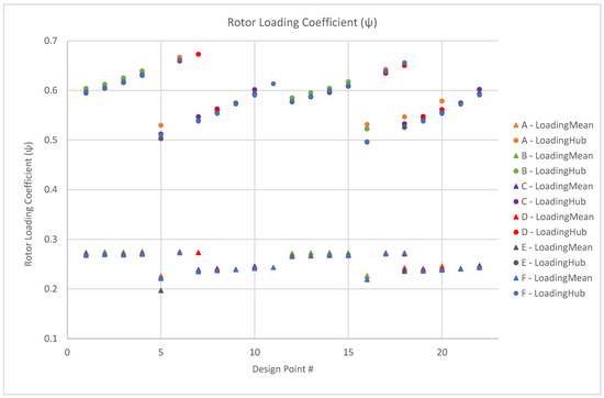
Figure 18.
Variations in the rotor loading coefficient with the different rotor blade parameters.
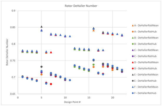
Figure 19.
Variations in the rotor DeHaller with the different rotor blade parameters.
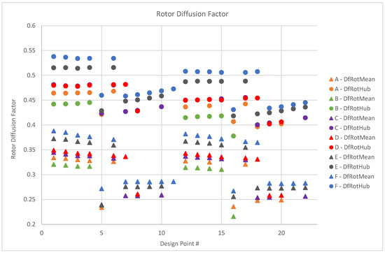
Figure 20.
Variations in the rotor diffusion factor with the different rotor blade parameters.
Figure 21 and Figure 22 present the results for the stator through-flow streamline calculation. Based on the DeHaller number, the stator is highly loaded, both on the meanline and hub, due to the high axial velocities with an increased rotor swirl and an introduced ramp on the rotor flow path which expectedly increases the velocity and the loading further downstream in the stator. Higher diffusion factors are satisfactory for the stator, with a constraint of <0.6; all of the design points satisfy the criteria.
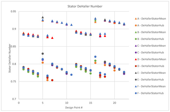
Figure 21.
Variations in the stator DeHaller factor with the different stator blade parameters.
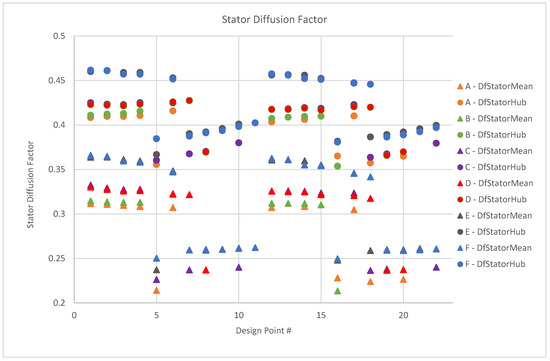
Figure 22.
Variations in the stator diffusion factor with the different stator blade parameters.
Design points 5 and 16 (DP5 = HtrInlet = HtrOutlet = 0.56–DP16 = HtrInlet = 0.56, HtrOutlet = 0.57, respectively) present anomalies in the data pattern for both rotor and stator through-flow analysis. For the rotor, both design points at iteration E and F are calculated with reduced hub loading and more favourably diffusion factors. The associated stator design for these points is highly loaded at both hub and on meanline, however, investigation into the use of IGV’s to reduce stator loading can be conducted in future works. In conclusion of the through-flow analysis, input parameters associated with design points 5 and 6 for iteration E and F are chosen for further design evaluation (see Table 12). Preliminary blade geometry for further analysis may also be seen in Table 13 and Figure 23.

Table 12.
Numerical results of the chosen design points from the through-flow calculation.

Table 13.
Preliminary blade parameters.
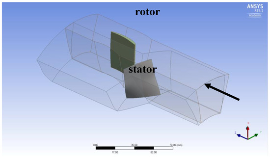
Figure 23.
Preliminary view of the rotor and stator.
4. Conclusions
The preliminary objective of this paper was to further investigate the potential application of micro gas turbine propulsion systems for tactical military UAVs through the use of a converted micro-turbojet. It is proposed that with the use of a continuously variable coupling introduced between the fan and an existing micro-turbojet engine, the ability to change gear ratios while maintaining the core running at its optimum enables an operation in a wider gamut of conditions and enhances the performance and scope of tactical UAV missions. The main objective was accomplished by the completion of three separate but dependent design studies for the conversion of a micro-turbojet to a turbofan. This design methodology follows similar processes involved in the design of gas turbine propulsion systems in the industry. The results and conclusions of this study are intended to further validate the initial hypothesis that the conversion of existing systems while maintaining a simple single spool configuration (thus potentially reducing costs and shortening the design process, with no changes to the core design) provides a more efficient and cost-effective process for the micro gas turbine industry.
4.1. Viability of Micro Turbine Engines for Tactical Military UAVs
It is found that advanced propulsion systems for increased speed and endurance are currently of predominant interest for military applications. From a comprehensive market study, it is found that the current utilization of MTEs is only found in larger UAV architectures, in a typical range of 3000–14,000 kg MTOW. This UAV classification mostly performs the role of intelligence gathering, reconnaissance and communications relay platforms, and common propulsion systems include those adapted from very light training/business aircrafts. From an extensive review of the literature and the markets, it is concluded that, currently, there is limited application of MTEs in the production of UAVs under 600 kg, with the majority found in home builds. It is of the author’s opinion that small tactical UAV upgraded MTE propulsion systems can extend their current role to be used for immediate deployment for armed forces on the ground for close recon or strike missions. The speed of such UAVs, considering relative size, can make detection and interception challenging, and with the continued research of UAV swarming and co-ordination, has the potential to make small tactical UAVs far more effective than current ones. In conclusion, considering the success of the Airbus SAGITTA project, the evidence suggests that MTEs are an emerging technology with strong applications for tactical UAVs. A technology survey is conducted for currently available micro turbine engines of all configurations. It is noted that there is a significant lack of turbofans and to a certain extent of turboprop configurations, in an already limited market that consists mainly of turbojets intended for hobbyists. From a comparison study of the ArticShark UAV, a micro turbine turboprop engine was retrofitted to the existing platform as a replacement for a more conventional rotary engine. The MTE propulsion system doubled the endurance time of the UAV, due to the overall improved propulsive efficiency of the gas turbine compared to the ICE. It is noted, however, that a similar comparison study cannot be performed for turbojet or turbofan configurations, as most current UAV architectures of the explored MTOW are not designed for transonic flights.
4.2. Conversion Study
As part of the conversion study, a baseline micro-turbojet is selected so that the performance may be evaluated before and after the proposed conversion. Based on the availability of experimental data, the BMT 120 KS micro-turbojet is selected as the baseline model. Using GasTurb 13 engine performance software, the original baseline model was first generated to validate the simulation against experimental and manufacturer data. The simulation of the baseline turbojet shows good agreement between the data, with the core nominal speed at 120 kRPM, a simulated thrust of 130 N in comparison to the recorded experimental value of 136.6 N, and a simulated fuel mass flow of 0.00472 kg/s in comparison with 0.0063 kg.
The converted turbofan engine model is then generated, where the parameters from the baseline model are combined with additional input to form the core stream of the turbofan. A scaled fan performance map from the publicly available NASA quiet engine program is used to evaluate the design point performance of the engine at varying fan operation parameters. In addition, we studied the operation of the fan at varying speeds, whilst the core remains at an optimum, through the use of a continuous variable gearbox, thus enabling a single spool platform for simplicity. It is found that the fan operation at close to the maximum spool speed yields significantly higher thrust values of 180 N > 130 N, a 38.46% increase. Conversely, the fan speed operation at 13,068 RPM yields a significant increase in TSFC of 60 g/(kN*s) > 36 g/(kN*s), a 65.8% increase. In conclusion, the results show that the converted turbofan has the potential to extend the operating parameters beyond those of the turbojet for the flight condition of the UAV, dependent on requirements, i.e., an increased speed performance for the UAV dash, or an increased endurance performance with low fuel consumption.
4.3. Preliminary LPC Design
The preliminary aerodynamic design of the low-pressure compressor to be coupled with the studied baseline turbojet is performed. One-dimension meanline and two-dimensional through-flow methods are used to calculate the performance of the compressor at the design point for a variety of input parameters. ANSYS Vista is used to rapidly study the performance through the iteration of the parameters. The comprehensive study is concluded with a set of LPC parameters, as seen in Table 12, to continue the design process in future works.
Author Contributions
J.L. was the student who conducted this research and drafted the paper and A.P. was the supervisor who conceived of the topic, the concept of this investigation, checked the results and provided the final draft.
Funding
This research received no external funding.
Conflicts of Interest
The authors declare no conflict of interest.
Appendix A
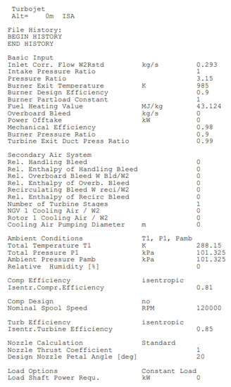
Figure A1.
Baseline BMT 120 KS Turbojet input parameters to GasTurb 13 Software.
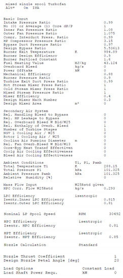
Figure A2.
Basic input parameters for the micro turbojet GasTurb engine model.
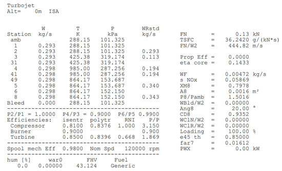
Figure A3.
GasTurb simulation results for the baseline turbojet, test facility.
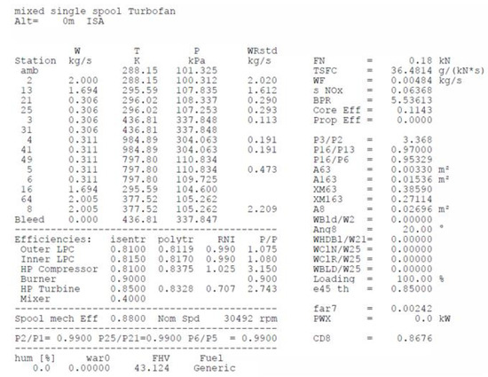
Figure A4.
GasTurb simulation results for the fan speed 30,492 RPM.
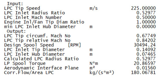
Figure A5.
GasTurb model LPC design parameters.
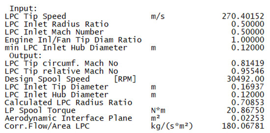
Figure A6.
LPC design in GasTurb software for the annulus diameter 0.17 m.
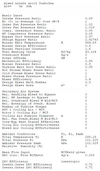
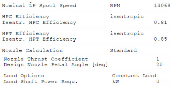
Figure A7.
GasTurb Turbofan engine model input parameters—fan at 13,068 RPM.
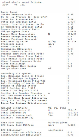
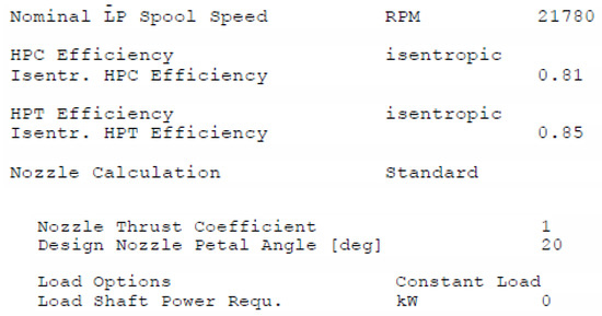
Figure A8.
GasTurb Turbofan engine model input parameters—fan at 21,780 RPM.
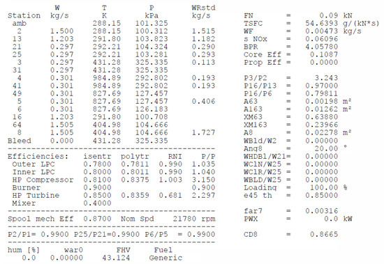
Figure A9.
GasTurb simulation results for fan speed 21,780 RPM.
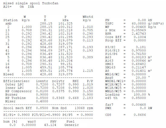
Figure A10.
GasTurb simulation results for fan speed 13,068 RPM.
References
- Cukurel, B.; Kadosh, K. Micro-Turbojet to Turbofan Conversion via Continuously Variable Transmission: Thermodynamic Performance Study. J. Eng. Gas Turbines Power 2016, 139, 022603. [Google Scholar]
- İlhan, M.; Gürbüz, M.; Acarer, S. Aerodynamic Design Investigation of HPT-Driven Low-Pressure Compression System for Variable-Speed Micro UAV Engine. In Proceedings of the ASME Turbo Expo 2018: Turbine Technical Conference and Exposition GT2018-76677, Phoenix, AZ, USA, 17–21 June 2018. [Google Scholar]
- Ministry of Defence and Military Aviation Authority. Regulatory Article (RA) 1600: Remotely Piloted Air Systems (RPAS). 2015. Available online: https://www.gov.uk/government/publications/regulatory-article-ra-1600-remotely-piloted-air-systems-rpas (accessed on 15 June 2018).
- Soares, C. Microturbines Applications for Distributed Energy Systems; Elsevier/Butterworth-Heinemann: Amsterdam, The Netherlands, 2007. [Google Scholar]
- Nelson, J.R.; Dix, D.M. Development of Engines for Unmanned Air Vehicles: Some Factors to be Considered; Institute for Defense Analyses: Alexandria, VA, USA, 2003. [Google Scholar]
- Kringe, D.S. Performance Evaluation of a Micro Gas Turbine Centrifugal Compressor Diffuser. Master’s Thesis, Faculty of Mechanical and Mechatronic Engineering at Stellenbosch University, Stellenbosch, South Africa, 2013. [Google Scholar]
- Burger, C. Design Procedure of a Compact Aerodynamic Crossover Diffuser. Master’s Thesis, Stellenbosch University, Stellenbosch, South Africa, 2016. [Google Scholar]
- Oppong, F. Micro Gas Turbine Performance Evaluation; Faculty of Engineering at Stellenbosch University: Stellenbosch, South Africa, 2016. [Google Scholar]
- Smit, F.V. Investigating the Design of the Turbine Stage of a Specific Micro-Gas Turbine Engine; Stellenbosch University: Stellenbosch, South Africa, 2014. [Google Scholar]
- De Villiers, C.L.B. Design of a Centrifugal Compressor for Application in Micro Gas Turbines. Master’s Thesis, Faculty of Engineering at Stellenbosch University, Stellenbosch, South Africa, 2014. [Google Scholar]
- Giffin, R.; Parker, D.; Dunbar, L. Experimental Quiet Engine Program Aerodynamic Perfromance of Fan A; Report No. NASA CR 120858; NASA: Washington, DC, USA, 1971.
© 2019 by the authors. Licensee MDPI, Basel, Switzerland. This article is an open access article distributed under the terms and conditions of the Creative Commons Attribution (CC BY) license (http://creativecommons.org/licenses/by/4.0/).