Abstract
The low regression rates for hydroxyl-terminated polybutadiene (HTPB)-based solid fuels and poor mechanical properties for the alternative paraffin-based liquefying fuels make today hybrid rocket engines far from the outstanding accomplishments of solid motors and liquid engines. In this paper, a survey is conducted of several innovative methods under test to improve solid fuel properties, which include self-disintegration fuel structure (SDFS)/paraffin fuels, paraffin fuels with better mechanical properties, high thermal conductivity fuels and porous layer combustion fuels. In particular, concerning HTPB, new results about diverse insert and low-energy polymer particles enhancing the combustion properties of HTPB are presented. Compared to pure HTPB, regression rate can be increased up to 21% by adding particles of polymers such as 5% polyethylene or 10% oleamide. Concerning paraffin, new results about self-disintegrating composite fuels incorporating Magnesium particles (MgP) point out that 15% 1 μm- or 100 μm-MgP formulations increase regression rates by 163.2% or 82.1% respectively, at 335 kg/m2·s oxygen flux, compared to pure paraffin. Overall, composite solid fuels featuring self-disintegration structure appear the most promising innovative technique, since they allow separating the matrix regression from the combustion of the filler grains. Yet, the investigated methods are at their initial stage. Substantial work of refinement in this paper is for producing solid fuels to fulfill the needs of hybrid rocket propulsion.
Keywords:
hybrid; regression rate; self-disintegration; HTPB; paraffin; low-energy polymer; magnesium 1. Introduction
Hybrid engines testing dates back to the very beginning of rocket propulsion development, both in USA and Russia. The famous American pioneer Robert H. Goddard started his experiments by injecting little quantities of graphite into a small combustion chamber, aiming at controlling burning rate, achieving stop/restart capability, and avoiding the hazards of large amounts of fuel stored in the combustion chamber. Because of the complexity of feeding powder into the combustor, Goddard eventually turned to liquid propulsion and in 1926 was able to launch the first liquid rocket engine reaching 14 m altitude, followed by 33 more launches up to 1941 [1]. The famous Russian designer Sergei Pavlovich Korolev [2], in 1933, was able to reach 1500 m altitude with the maiden flight of the GIRD-09 hybrid rocket engine (HRE) burning gelled gasoline and LOx.
In spite of these very precocious activities, still today hybrid rocket propulsion is far from the huge success later obtained by the companion liquid and solid rocket propulsion. In most cases, it happened that only the solid and liquid rocket systems were developed to operational status. In fact, HRE found applications for small-size engines, but still today no large-size engine exists able to compete with the relative simplicity of solid propulsion or the superior performance of liquid propulsion. Yet, several attempts were made. A first example is the study of high-energy space engines promoted by NASA in the mid-1960s. United Technology Center-Chemical Systems Division (UTC-CSD) considered [1] a hypergolic and very energetic reaction between Li and F2 by incorporating a mixture of Li+LiH in a matrix of HTPB, while F2 was mixed with O2 to create the mixture F2+O2 (FLOx). The versatility of hybrid propulsion easily allowed to optimize the performance of an otherwise traditional hydrocarbon propellant system. The hybrid engine featured an 11-port wagon wheel solid grain. This system was throttleable, burned smoothly, and exhibited impressive high performance with a specific impulse efficiency of 93%, achieving a delivered vacuum specific impulse of about 380 s with a nozzle area ratio of 40. A picture of the fire test was reproduced on the cover page of Aviation Week of 26 January 70.
A second example is the high-energy boosters for space launchers. Following the tragic accident of the Challenger Space Shuttle solid boosters in 1986, NASA considered replacing them with hybrid units aiming at increasing safety while decreasing the cost of space access. Two experimental programs, Hybrid Technology Options Project (HyTOP) and Hybrid Propulsion Demonstration Program (HPDM), were carried out for years at Marshall Space Flight Center (MSFC) in cooperation with Defense Advanced Research Projects Agency (DARPA). But after intensive static fire testing of large hybrid engines burning LOx/HTPB (8- or 15-port wagon wheel solid grain) capable of 1.1 MN thrust in vacuum up to 80 s burning time, NASA gave up despite the potential advantages for safety, cost, and versatility of propellant selection.
The difficulties that hindered the full-scale development of HRE essentially regard the solid-phase fuel: in the classical hybrid formulations, this consists of HTPB (borrowed from composite solid propellants), which has good mechanical properties but too low regression rates; the opposite is true for the alternative paraffin-based liquefying fuels. Moreover, the intrinsic architecture of HRE forces a macroscopic diffusion flame conducive to poor combustion efficiency compared to solid and liquid rockets.
2. Literature Survey and Objective
After so much history, the “hybrid option” remains very attractive. The inherent safety in both manufacture and operation (zero TNT equivalent, insensitivity to cracks and defects), low-cost and thrust throttleability, and terminate/restart capability [3] make hybrid rocket engines an economical alternative to suborbital flight, space tourism, small satellite orbital injection [4], booster and upper stage [5], Lunar [6] and Mars lander spacecraft [7]. Unfortunately, the low regression rates of classical hybrid fuels limit the motor thrust, resulting in complicated fuel grain design and scaling, because of the low heat feedback (radial blocking effect and low thermal conduction of gasified products for non-metallized or non-radiating fuel) from the thin diffusion flame to the fuel surface.
Methods for increasing the fuel regression rate mainly consist of improving the heat feedback (nano-metallized fuels), fostering condensed phase reactions (using high-energy binder such as Guanidinium Azo-Tetrazolate (GAT) [8] and Glycidyl Azide Polymer (GAP) to decrease heat of degradation or adding ammonium perchlorate (AP) [9] to get oxygen-poor fuels), resorting to low enthalpy of vaporization fuels like paraffin liquefying fuels [10,11,12,13,14] to promote a mass-transfer mechanism, enhancing oxidation turbulence (swirling injector [9,15,16] or helicoidally shaped spikes port injector [17]), designing multi-port grain (star and wagon wheel type or porous hybrid grains to increase the burning area [18]) and applying more reactive oxidants (LO2-LF2 [19] and LO2-N2O [20,21]). Kuo et al. [22,23] reported 105% and 123% increase in regression rate, at the average oxygen mass flux = 112 kg/m2·s, by adding respectively 13% in mass of Alex (100 to 150 nm aluminum) and Viton-A coated Alex to a standard HTPB matrix. DeLuca et al. [24] found that introducing 11.2% in mass of AlH3 into an HTPB matrix promotes the regression rate of this fuels by 150% at = 11 kg/m2·s. Carmicino and Russo-Sorge [25] tested a laboratory-scale hybrid rocket burning gaseous oxygen in a center-perforated cylindrical solid grain and, with respect to pure HTPB, verified for several high-energy fuel additives limited effects in terms of regression rate increase (say, 15–20% based on oxygen mass flux) but also a considerably high characteristic-velocity and impulse efficiencies (around 95% and 92%). Karabeyoglu et al. [13,14] demonstrated 3 to 4 times higher regression rates than those of conventional polymeric fuels for a class of paraffin-based fuels, suggesting its great potential for high power HREs after solving the mechanical properties of paraffin.
In this framework, a series of innovative techniques is currently under investigation at Nanjing University of Science and Technology (NUST) in order to overcome the solid fuel deficiencies so far experienced. Shen et al. [26,27,28,29,30,31,32] verified new concepts such as:
- Insert and low-energy polymer particles enhancing HTPB combustion.
- Self-disintegration fuel structure (SDFS) [26,27,28].
- Porous layer combustion fuels [29,30].
- High thermal conductivity fuels [31].
- Paraffin fuels with better mechanical properties [32].
In this paper, each of the above new concepts is discussed separately and representative results are given for everyone. In addition, new experimental results are reported about the combustion performance of HTPB loaded with low-energy polymer particles (item 1) and paraffin-based SDFS fuels (item 2).
3. Experimental
The combustion characteristics of all tested fuels were examined in a gaseous oxygen flow by a 2D-radial hybrid combustion burner. All experiments were conducted at 1 MPa. Only the implemented radial burner is quickly described in this section. Preparation, composition, and properties of fuels are reported under the appropriate section headings that follow.
Combustion Characterization
The 2D-radial hybrid combustion burner (Figure 1) was previously described [26,27,28,29,30,31,32] and is based on the original design by SPLab [33,34]. Gaseous nitrogen is used to stabilize the chamber pressure during combustion and terminate the HTPB-O2 reaction after turning off oxygen, while compressed air is used to save nitrogen before combustion and cool off the chamber after combustion. Gaseous oxygen is axially injected into the fuel grain port (a center perforated cylinder) at a mass flow rate of 5 g/s, controlled by a Bronkhorst F202 flowmeter. An automatic control system, which is equipped with a logical circuit, a pressure transducer, four solenoid valves, and four electromagnetic relays, governs the solenoid valves opening or closing every 30 ms to keep the combustion chamber in a quasi-steady state. A charge (4.5 mm OD × 0.8–1.2 mm thickness) of B/KNO3 (40/60) which is fixed upstream of the fuel grain port is activated by an Nd:YAG laser, followed by the ignition of the inner surface of the cylindrical fuel grain under oxygen flow. A high-speed camera is used to record the regression process of the inner burning surface upstream cross-section at 1500 fps.
Figure 1.
Optical image of the 2D-radial hybrid propulsion burner system.
The high-speed photographs are processed as ΔD(t) vs. t, Gox(t) vs. t, ṙ(t) vs. t, and ṙ(t) vs. Gox(t), as discussed in detail in References [31,33,34]. ΔD(t) evolution is the diameter variation of the inner burning surface of the regressing fuel grain at time t, is the oxygen mass flux (mass flow rate per unit area, kg/(m2·s)) at time t, and is the regression rate of the solid fuel at time t. The resulting function is used to evaluate the combustion characteristics of the fuel under study. Finally, the mass burning rate from the central port fuel grain is simply expressed as , where is the combustion surface area and the density of the fuel. For the regression rate, the classical power law empirical formula of hybrid combustion, based on oxidizer mass flux, is typically used.
where the reference starting time is set, for each test, as the instant at which the external ignition stimulus (laser on) is first applied to the primer charge while the ignition time tign = t0 + Δtign is conventionally taken as the first instant at which the sample cross section appears fully inflamed. Thus, the observed ignition delay Δtign includes laser activation, primer charge ignition, and fuel sample inflammation. Assuming a quasi-steady burning regime has established, all plotted regression rate curves start at tign and the investigated measurement range cover the whole combustion process until extinction. In a log plot, nr is the slope of the regression rate straight line evaluated according to Equation (1).
The 2D-radial burner is a lab scale tool and one of its advantages is the possibility of visual and direct observation of the hybrid combustion process. Other 2D burners were designed and are in use at SPLab implementing a simpler planar geometry consisting of a single or double solid fuel slab [33,34]. Due to the different boundary conditions, the experimental regression rates differ for each burner. For the standard HTPB fuel, under the same operating conditions (about 0.15 MPa for the planar burners), the measured regression rates in the 2D-radial burner is 80% larger than that in the companion 2D-double slab, in turn 26% larger than the corresponding 2D-single slab, the slowest of the crop [33]. With reference to Figure 6 of Reference [25], results from the 2D-radial burner are reasonably close to the line denoted as “HTPB Literature”. Other fitting expressions of the solid fuel regression rate, for example, based on total mass flux as recommended in Reference [25], can be implemented as well. Since a large number of results was obtained as above described at SPLab and NUST, for consistency data processing is carried out in this work using Equation (1) based on the oxidizer mass flux, as done in the vast majority of the literature. Moreover, keep in mind that the 2D-radial burner provides instantaneous values of regression rate, while data from engines are in most cases space- and time-averaged.
4. Low-Energy Polymer Particles/HTPB
Although energetic ingredients are the preferred additives in conventional studies, insert and low-energy polymer particles offer an additional method to enhance HTPB combustion. In this work, previously unreported PE paraffin (low molecular mass polyethylene), oleamide, polydextrose, and polyethylene glycol (PEG) particles are all additives with poorer combustion performance and lower decomposition temperature than HTPB. PE paraffin is a commercial polymer which has a lower regression rate than HTPB definitely [35]. Oleamide (–NH2 groups) particles reacting with -OCN groups and reducing the mechanical properties of HTPB, potentially reduce the degree of polymerization and decomposition heat. Polydextrose or PEG particles provide a certain amount of oxygen and their surface contains very few –OH groups reducing mechanical properties only very slightly. These four kinds of polymers are extremely low-cost (less than 1 $/kg), while HTPB prepolymer needs 15 $/kg without considering the more expensive ingredients dioctyl adipate (DOA) and isophorone diisocyanate (IPDI). The cost can further be reduced by introducing a certain amount of polymer particles without lowering the regression rate.
4.1. Low-Energy Polymer Particles/HTPB Fuel Preparation
HTPB, IPDI, DOA, dibutyltin diacetate (TIN), and four kinds of polymer particles (PE paraffin, oleamide, polydextrose, and PEG) are the raw materials used for sample preparation. HTPB was purchased from Liming Research and Design Institute of Chemical Industry Co. (Luoyang, China). with a number-average molecular mass of 2940 and –OH content of 0.787 mmol/g. IPDI, DOA and TIN were obtained from Aladdin. The physical properties of PE paraffin, oleamide, polydextrose, and polyethylene glycol particles are listed in Table 1.

Table 1.
Physical properties of the tested polymer particles.
The compositions of the tested polymer particles/HTPB composite fuels are tabulated in Table 2. The preparation process of HTPB-based fuels was described in our previous studies [31] and is shown in Figure 2. The cured HTPB was prepared at a ratio NCO: OH of 1.05. Briefly, the corresponding content of HTPB was dispersed under vacuum (<5 kPa) with a blade mixer rate of 200 rpm for 10 min, followed by DOA and TIN for 5 min. The resulting mixture was mixed with polymer particles for 20 min, followed by IPDI stirring for another 10 min. The uncured polymer particles/HTPB fuels were cast into several molds to get 4–6 samples (16 mm OD × 4 mm ID × 30 mm length). The samples were solidified at 36 °C in an oven for 23 h and a 2 h post-cure bake at 60 °C.
Table 2.
Composition of the tested 0, 5%, 10%, and 20% polymer particles/HTPB composite fuels.
Figure 2.
Procedure for the preparation of polymer particles/HTPB (hydroxyl-terminated polybutadiene) composite fuels.
4.2. Low-Energy Polymer Particles Morphology
The morphological features and diameter distribution of raw polymer particles were detailed by Confocal Laser Scanning Microscope (CLSM, LEXT OLS3100, Olympus, Tokyo, Japan) on glass substrates; see Figure 3. PE paraffin, oleamide, polydextrose, and PEG respectively have an average diameter of 49.9 μm, 425.4 μm, 44.0 μm, and 182.0 μm.
Figure 3.
CLSM (Confocal Laser Scanning Microscope) images of (a) PE paraffin, (b) oleamide, (c) polydextrose, (d) PEG6000 particles.
4.3. Low-Energy Polymer Particles/HTPB Composite Fuel Combustion
Figure 4 shows the regression state of 5% PE particles/HTPB composites during burning at t = 0 s (tign), 1 s, 2 s, 3 s and 5 s, respectively. The red circle represents the diameter of the initial internal burning surface diameter (4 mm). The brightness of the 5% PE particle formulation image is darker than HTPB, suggesting less energy release compared to HTPB and making difficult regression data collection. From the viewpoint of cross-section diameters which were processed as ṙ(t) vs. t, the 5% PE particle formulation shows a slightly enhanced regression rate compared to HTPB.
Figure 4.
Photograph of regression process of pure HTPB (top) and polymer particles/HTPB (bottom) fuels. All pictures were obtained at the same exposure and aperture.
The fuel density was calculated from the sample mass and dimensions. HTPB containing PE paraffin (5%, 10%, and 20%), oleamide particles (5%, 10%, and 20%), 10% polydextrose, and 10% PEG6000 particles have a density of 922 (pure HTPB), 925, 927, 931, 918, 917, 914, 980 and 958 kg/m3. Compared to the HTPB matrix alone, the tested fuels reinforce the regression rate at Gox = 350 kg/m2·s and Gox = 150 kg/m2·s, respectively, as shown in Figure 5 and Table 3. This indicates that the optimal addition of polymers is 5% PE particles (up to ≈21% increase) and 10% oleamide particles (up to ≈17% increase), despite the insert polymer particles depress combustion performance in terms of released energy.
Figure 5.
(a,c,e) Regression rate and (b,d,f) percent increase in regression rate vs. oxygen mass flux for low molecular mass polyethylene (PE paraffin) (5%, 10%, and 20%)/HTPB, oleamide (5%, 10%, and 20%)/HTPB, 10% polydextrose/HTPB, and 10% PEG6000/HTPB composite fuels, respectively.
Table 3.
rf increase and fitting results of rf/Gox curves for polymer particles/HTPB composite fuels.
From the viewpoint of burning surface (Figure 6), 10% PEG formulation appears more uniform and smoother with several holes which were left by PEG particles melting and flowing, while the melted and partly pyrolytic HTPB reformed porous edge with gas and some black carbon products attaching on the surface. Excess PEG particles are more susceptible to melting, pyrolysis and evaporation, resulting in reduced heat feedback to the HTPB surface, blocking the regression rate of HTPB slightly and exposing the poor combustion properties of polymer particles. 10% oleamide features a relatively large ar as well as low nr and shows a better regression rate than 5% and 20%, suggesting a convenient compromise of poor oleamide combustion performance and a relatively lower degree of polymerization. The oxygen element in polydextrose and PEG particles yield no enhancement on HTPB regression rate due to the pyrolysis and evaporation process into the flame zone, involving no condensed phase reaction.
Figure 6.
Images of (a) pure HTPB and (b) 10% PEG particles/HTPB composite fuel grains after terminating combustion.
5. Self-Disintegration Fuel Structure (SDFS)/Paraffin
SDFS is a concept borrowed from composite modified double-base propellant [36] and new for hybrid propellant burning, whereby the binder will release fuel particles from a block of composite solid fuel over some critical threshold condition (for example, a melting temperature). Combustion visualization shows a lot of burning granules of the implemented filler escaping from the burning surface into the gas flow; see Figure 7. During combustion, the solid fuels disintegrate into many small parts due to melting and decomposition of binder, and flow out with the sweep of oxygen flow, realizing the structural self-disintegration phenomenon. The self-disintegration process needs less energy and reaction time than the evaporation and thermal decomposition processes of conventional fuels so that the mass transportation per unit time can greatly improve, and the regression rate and mass burning rate will be enhanced. Thus, the scattering of particles associated with the self-disintegrating matrix structure can promote propulsion performance.
Figure 7.
Self-disintegration mechanism of particle/paraffin composite fuels [28]. Copyright Begell House (2017). Reproduced with permission.
Being subject to a variety of chemical and physical effects, the effect of the particle size is not obvious: in general, large filler particles carry away more mass and volume from the regressing surface when they escape into the gas flow, while small filler particles offer a better diffuse particle dispersion and a more abrupt particle scattering. So far four cases were implemented; each is recalled in the following subsections. Paraffin was used as a binder: Paraffin #90 in Reference [26] and Paraffin #58 in References [27,28,32] and in this work; their main properties are shown in Table 4.
Table 4.
Physical properties of the tested kinds of paraffin.
5.1. Polystyrene Particles/Paraffin Fuel Combustion
In the first attempt to realize an SDFS structure, inert low-energy polystyrene (PS) particles (D301) were blended with paraffin #90 [26]. Two sizes of PS grains were tested: small (0.60–0.71 mm) and large (0.85–1.00 mm) ones. The experimental trend of the associated SDFS fuel regression rate is the same as that of pure paraffin, but its value is higher up to ~25% and increasing for growing PS particles load in the range 5% to 15%. For the tested fuel formulations, the power nr decreases with increasing particle size and thus it affects differently the regression rate values trends under high and low oxygen mass flux. In general, for large Gox values, the small size PS grains revealed more efficient than large size, and vice versa for low Gox values. Only for 15% PS load, the formulation with large particles appears just slightly faster over the entire test range.
5.2. Double-Base Particles/Paraffin Fuel Combustion
In the second example of SDFS structure, active particles of double-base (DB) propellant were blended with paraffin #58 [27]. Although the presence of solid propellant is not accepted in hybrids for space exploration missions, this formulation is useful to check the validity of the SDFS concept. The loaded DB particles were small cylinders with 0.28 mm average diameter and 0.65 mm average length (ranging from 0.47 to 0.81 mm). During combustion, the settled particles are disaggregated from the molten paraffin matrix and detached from the burning surface due to the oxidant flow blowing. Over the range Gox = 50–350 kg/(m2·s), combustion runs show that the regression rates and the power nr of all tested formulations raised monotonically with the loaded mass % of DB particles; see Table 5. Moreover, the more content of particles the more splatter. The average regression rates of formulations blended with 5%, 10%, 15%, and 20% particles in mass were increased by 30%, 38%, 47% and 59% with respect to pure paraffin, respectively.
Table 5.
rf increase and fitting results of rf vs. Gox for double-base (DB) particles/paraffin composite fuels with 0, 5%, 10%, 15%, 20% DB showing increasing regression rate and slope nr for increasing DB load [27]. Copyright Begell House (2017). Reproduced with permission.
5.3. Low-Density Polyethylene Particles/Paraffin Fuel Combustion
In the third example of SDFS structure, inert low-energy particles of low-density polyethylene (LDPE) were blended with paraffin #58 [28]. Compared with pure paraffin, the average regression rates of formulations blended with 5% and 10% LDPE particles increased by 9.0% and 22.2%, respectively. However, for LDPE addition of 15% and 20%, the average regression rates were reduced by 5.5% and 13.2%, which was due to high melting point and high decomposition temperature of LDPE. Thus, the regression rates first increased and then decreased with an increasing load of LDPE particles.
As to the effects of the particle size, see Table 6, the power nr of the regression fitting law decreased with increasing particle size implying that small particles favor regression rates under high oxygen mass flux while large particles favor regression rates under low oxygen mass flux. For example, the regression rates of fuels loaded with 15% LDPE particles, at Gox = 367 kg/(m2·s), increased by 21.0%, 11.2%, and –1.6%, respectively, moving from small (0.18–0.45 mm) to medium (0.45–0.75 mm) and to large (0.75–1.00 mm) particles.
Table 6.
rf increase and fitting results of rf vs. Gox for low-density polyethylene (LDPE) particles/paraffin composite fuels, 15% LDPE showing decreasing slope nr for increasing particle size [28]. Copyright Begell House (2017). Reproduced with permission.
A significant finding is that comparing the combustion response of the same LDPE/paraffin formulation, manufactured as an SDFS composite fuel rather than just a simple blend, points out quite a different behavior in terms of regression rate. For example, for the kinds of paraffin with 5% and 10% LDPE previously mentioned, the SDFS samples exhibit an increase of the average regression rate by 9.0% and 22.2% respectively, in marked contrast with the corresponding reduction by 39.0% and 58.9% featured by the blend formulations; for details, see Section 8. Being the ingredients and formulations the same, only the internal fuel structures are different. This discrepancy is direct proof that the SDFS composite fuels can play an important role in promoting regression rates.
5.4. Magnesium Particles/Paraffin Fuel Preparation and Combustion
Two sizes of magnesium particles (1 and 100 μm) were chosen to analyze the effects on combustion of composite fuels based on paraffin #58. Their main properties are listed in Table 7 while their SEM images are shown in Figure 8. The tested MgP have high purity, and the specific surface area of small particles is much bigger than that of large particles, indicating that the small magnesium powders have higher reactivity and are easier to burn. Figure 9 shows optical microscope images of the two MgP/paraffin composite fuels and Figure 10 shows two samples ready for combustion test. The composition of the tested MgP/paraffin fuels is indicated in Table 8.
Table 7.
Main properties of the tested magnesium particles.
Figure 8.
Scanning Electron Microscopy (SEM) images of small (a) and large (b) magnesium particles.
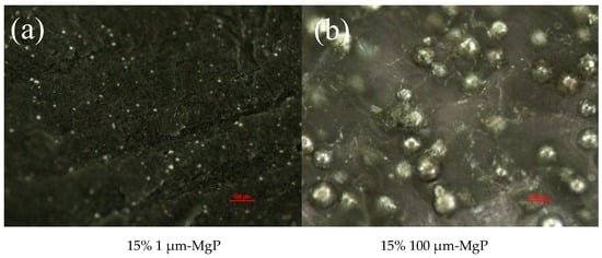
Figure 9.
Optical microscope images of small (a) and large (b) magnesium particles/paraffin composite fuels.
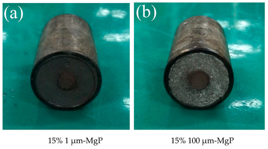
Figure 10.
Combustion test samples of small (a) and large (b) magnesium particles/paraffin composite fuels.
Table 8.
Composition of the tested magnesium particles/paraffin composite fuels.
Figure 11 illustrates the regression process of magnesium particles/paraffin composite fuels and the arrows point out the burning Mg particles which disintegrate from the paraffin matrix. As the figure suggests, the structural self-disintegration of Mg particles/paraffin composite fuels was more obvious under high oxidizer mass flow rate, and the flame of magnesium particles was bright which shows high energy.
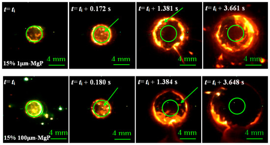
Figure 11.
Combustion surface regression process of small (top) and large (bottom) magnesium particles/paraffin composite fuels.
The relationships between the regression rate and oxidizer mass flux of magnesium particles/paraffin composite fuels are illustrated in Figure 12. As the figures show, the influence of 1 μm-MgP on the combustion characteristics of composite fuels is quite different from that of 100 μm-MgP. The regression rate of formulation 15% 1 μm-MgP improved at high oxidizer mass flux but markedly decreased with decreasing oxidizer mass flux. On the contrary, the regression rate of formulation 15% 100 μm-MgP increased over the whole range of oxidizer mass flux and the increased percent was little dependent on the oxidizer mass flux. At Gox = 335 kg/(m2·s), the regression rate of formulations 15% 1 μm-MgP and 15% 100 μm-MgP increased by 163.2% and 82.1% with respect to pure paraffin, respectively, while at 100 kg/(m2·s), the regression rate respectively changed by −47.6% and 49.2%.
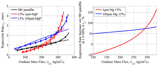
Figure 12.
rf vs. Gox (left) and percentage increase in regression rate (right) of magnesium particles/paraffin composite fuels, at 1 MPa, pointing out a strong particle size effect. The dotted lines are fitting curves according to the semi-empirical formula: .
The fitting results of rf vs. Gox for the two tested kinds of magnesium particles/paraffin composite fuels are shown in Table 9. The nr of formulation 15% 1 μm-MgP is much larger than that of formulation 15% 100 μm-MgP, which indicates that the regression rate of composite fuel with small size magnesium particles is significantly affected by oxidizer mass flux. The thermal properties of magnesium particles were tested to analyze the influence of their particle size on the combustion performance of composite fuels. Figure 13 shows the differential scanning calorimetry/thermogravimetry (DSC/TG) (TA instruments SDT600, Lindon, UT, USA) analyses in air flow of 30 mL/min, with a heating rate of 20 K/min: the small Mg particles have lower oxidation reaction temperature and active Mg content than the big ones, which is due to their higher specific surface areas and higher reactivity, so that they are easier to be oxidized.
Table 9.
rf increase and fitting results of rf vs. Gox for magnesium particles/paraffin composite fuels, 15% Mg showing decreasing nr for increasing particle size.
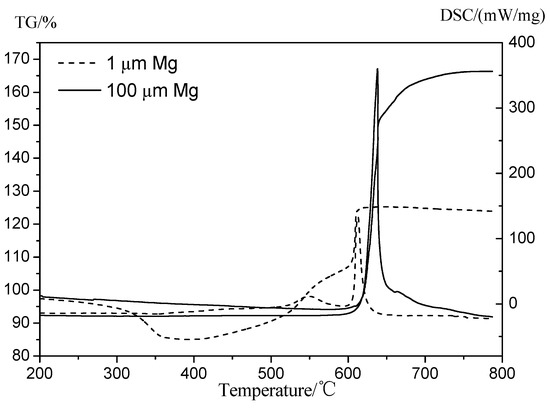
Figure 13.
Differential scanning calorimetry/thermogravimetry (DSC/TG) results of small (dotted lines) and large (continuous lines) Magnesium particles showing dependence on particle size. The curves with sharp peaks are the DSC analyses.
According to combustion tests, small Mg particles can increase the regression rate much more than the big ones under high oxidizer mass flux, because that small Mg particles have higher reactivity which is beneficial to increase the thermal feedback during the combustion process. At the same time, small Mg particles have better diffuse distribution in the paraffin matrix so that the dissociation and fly apart phenomena are more obvious. However, with the decrease of oxidizer mass flux, the regression rate of formulation 15% 1 μm-MgP reduced sharply below that of pure paraffin under 200 kg/(m2·s) oxidizer mass flux. This is due to an excessive MgO barrier layer attached to the burning surface (see Figure 14a) and blocking combustion rather than performing the structural self-disintegration phenomenon. The above facts suggest that 100 μm-MgP is easier to fly into the oxygen flow during paraffin melting while 1 μm-MgP is conducive to form an excess MgO barrier layer attached to the burning surface and blocking combustion.
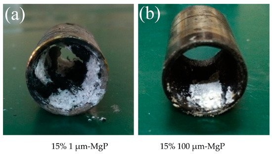
Figure 14.
Samples tubes after burning of small (a) and large (b) magnesium particles/paraffin composite fuels.
6. Porous Layer Combustion Fuels
This is another way to increase the combustion area of the regressing solid fuel and/or the reactivity of energetic particles (see the last paragraph). In composite solid fuels, a substance filler with a low decomposition temperature to gas or a fast burning rate leaves holes in the initial matrix after decomposition or burning, thus increasing the regressing surface area. For example, Azodicarbonamide (ADCA) decomposes at 150–306 °C while HTPB decomposes at 417–591 °C, thus forming a certain thickness of porous layer after the decomposition of ADCA particles, before HTPB melting and pyrolysis, during the burning of the composite fuel. Experimental results for ADCA/HTPB [30] point out the optimal level of 3% ADCA to enhance the regression rate and total thermal energy. Excess ADCA shifts the HTPB-O2 reaction to a high temperature, as well as increases the blocking effect, hindering heat transfer from the flame zone to the fuel surface and suppressing the combustion due to low combustion heat. The ADCA 19.7% final decomposition (at 800 °C) residues hinders the complete combustion reaction by intercepting the heat and oxygen from the diffusive exothermic reaction of HTPB with O2. Another instance of accelerating porous layer is given by metal hydride particles, typically containing large amounts of H2 that can be released at temperatures far below the combustion temperatures. The released H2 can be used for combustion and the remaining base metal can further react and combust, thus adding more thermal energy to the system. Experimental results in Table 10 and Reference [29] confirm a previously unreported porous layer mechanism of AlH3 improving combustion. A 50 μm thickness porous layer in AlH3/HTPB melting layer, which is exposed by rapidly released gas phase H2 transferring from AlH3 dehydrogenation during combustion, is determined by SEM and other techniques. The results showed that the low AlH3 content (≤10%) promotes the regression rate obviously, while excessive AlH3 content (≥20%) promotes only slightly as a result of aggregated Al2O3 attached on the burning surface, AlH3 endothermic dehydrogenation step and the blocking effect of the gaseous released H2. Nano- and/or micro-porous Al-crystals created by AlH3 dehydrogenation has a specific surface up to 15–20 m2/g, promoting the combustion processes. These local porosity effects are useful for both solid and hybrid rocket propulsion, as already discussed in References [37,38].
Table 10.
rf increase and fitting results of rf/Gox curves for AlH3 particles/HTPB composite fuels. Copyright Elsevier (2019). Reproduced with permission.
7. High Thermal Conductivity Fuels
Carbon nanotubes (CNT) act as an energy transfer media, accelerating the heat transfer and combustion performance of HTPB. Multiwall carbon nanotubes HTPB/MWCNT composites create a discontinuous three-dimensional heat conducting network due to their random orientation in composites, transferring heat from the combustion zone to a melting layer. Regression rates of HTPB-based solid fuels are expected to increase thanks to the enhanced thermal conductivity.
Since MWCNT tend to cluster into microscale aggregates, a uniform and stable dispersion was obtained [31] by dispersing 20–40 nm OD of MWCNT and a surfactant in an HTPB-toluene solution through high-energy ball milling, followed by toluene evaporation and isophorone diisocyanate (IPDI) cross-linked solidification. By adding MWCNT from 0% to 3% in mass, the viscosity of the uncured fluid MWCNT/HTPB composites is increased up to 964% at 120 °C; likewise, thermal conductivity and density increase while the heat of combustion decreases. MWCNT react with oxygen at ~500 °C, higher than the HTPB starting reaction temperature (~180 °C). Thus, MWCNT shifts the HTPB-O2 reaction temperature to a higher level.
Combustion tests carried out at the 2D-radial burner showed that HTPB containing 0.5%, 1%, 2%, and 3% MWCNT increase the instantaneous regression rate at Gox = 365 kg/(m2·s) and Gox = 150 kg/(m2·s), respectively, as shown in Table 11. The best fitting results are summarized in Table 11: the non-monotonic trends for both ar and nr parameters reflect the complexity of the burning process. Overall, these experimental results suggest that the optimal level of MWCNT is 1% and the addition of excessive filler (>2%) hinders the combustion characteristics of the HTPB/MWCNT composites by heat dissipation, high viscosity of the melting layer, low thermal energy release and high vaporization heat of excessive MWCNT agglomeration on the burning surface.
Table 11.
rf increase and fitting results of rf/ curves for hydroxyl-terminated polybutadiene/carbon nanotubes (HTPB/CNT) composites fuels [31]. Copyright Elsevier (2019). Reproduced with permission.
8. Paraffin Fuels with Better Mechanical Properties
Experimental results [32] show that the presence of additives usually decreases the regression rate of paraffin-based fuels. Paraffin #58 loaded by simple blend with six different additives was investigated: stearic acid, polyethylene wax (A-C®6A), ethylene-vinyl-acetate (EVA), low-density polyethylene (LDPE), polypropylene (PP), and high-density polyethylene (HDPE). Comparative mechanical tests, thermal performance tests (melting point and DSC), viscosity measurements and combustion tests were conducted for all fuels. With respect to pure paraffin, the presence of 5% additives caused a decrease of regression rate for all mixed formulations except the one using stearic acid. The reason is the effect of the additives augmenting the viscosity of the liquid molten paraffin, while stearic acid decreased the mix melting point from 58.3 °C (pure paraffin) to 55.8 °C.
In order to obtain a suitable paraffin-based fuel with both good mechanical properties and combustion performance, additives should be selected not increasing the melt liquid viscosity of the compound. As a matter of fact, an exponential relation was found in Reference [39] which correlates the regression rate of liquefying fuels with their liquid viscosity. Thus, the regression rate data of the tested paraffin-based fuels could be related directly to the viscosity of the corresponding liquid fuel samples and an increase in the liquid layer viscosity resulted in a decreased regression rate [32].
If the increase of viscosity can somehow be avoided, the detrimental effect on the regression rate is canceled. This is exactly what happened for the LDPE particles tested in Section 5.3, where the SDFS technique allowed paraffin to increase and not to decrease its regression rate, being the combustion process of LDPE particles shifted from the condensed phase directly to the gas phase. A comparison of the two manufacture techniques, a simple blend of the ingredients or SDFS composites, for paraffin #58 loaded with 5% and 10% LDPE, is shown in Table 12. It is seen that the SDFS samples (resorting to medium size LDPE particles) feature appreciably higher values of ar while nr is somewhat less.
Table 12.
Fitting results of rf vs. Gox for LDPE/Paraffin fuels comparing 5% and 10% LDPE addition by blend and by SDFS composites (M = medium particle size) [28,32]. Copyright Wiley (2017) and Begell House (2018). Reproduced with permission.
9. Concluding Remarks
After almost a century of progress [1,2,3], hybrid rocket propulsion still suffers the severe limitations of inadequate solid fuel behavior, with conflicting trends of regression rate and mechanical properties. This penalty hinders the development of large size HRE. Several innovative techniques to increase solid fuel performance were discussed in this paper. Overlapping effects in terms of combustion phenomena (for example, porosity for the SDFS approach) were not explicitly considered but intrinsically exist and should be taken into account in developing the above techniques. Composite fuels featuring self-disintegration structure (SDFS) [26,27,28] appears the best candidate approach to enhance regression rates, as discussed in Section 5. A meaningful result is that illustrated in Table 12 comparing regression rates for the same paraffin with the addition of 5% or 10% LDPE: dramatically different values are measured according to the manufacturing technique (blending or SDFS composites). SDFS leaves essentially unaltered the viscosity of liquid molten paraffin and therefore allows much higher regression rates.
A common finding for the tested formulations is that the optimum mass fraction of non-active filler or additive is in general relatively low and that an excess of it becomes quickly detrimental to combustion performance. Being subject to a variety of chemical and physical effects, the influence of particle size is more involved: in general, the power nr decreases with increasing particle size and this affects differently the regression rate values trends under high and low oxygen mass flux. A different trend was observed for DB/paraffin composite fuels because of the active nature of DB particles: both the regression rate and its slope vs. Gox increase with increasing DB load. Overall, best results were achieved by an SDFS structure using Mg powder in a paraffin matrix. This finding is somehow in agreement with the results obtained in small-scale hybrid engine fire tests [25], where different loads of Mg (15% metal, 15% hydride, and a mixture 15% Mg + 1% Fe) produced the largest increase of regression rate (about 12%, 14%, and 48%, respectively, based on total mass flux). Although encouraging results were achieved, the investigated methods are still at their initial stage. Substantial work of understanding and refinement in this paper is for producing solid fuels to fulfill the needs of hybrid rocket propulsion. At any rate, validation by fire tests in a small-scale engine is a mandatory step before attempting large-size HRE.
Funding
This work was supported by the Fundamental Research Funds for the Central Universities (Grant No. 30918011315).
Acknowledgments
Suhang Chen is grateful for the financial support received from China Scholarship Council. Thanks are due to Junzhou Pu for his help in the combustion tests. Thanks are also due for the great contribution of Luigi T. DeLuca in detailing the introduction of hybrid propulsion progress in our group, revising the language, and restructuring the entire article.
Conflicts of Interest
The authors declare no conflict of interest.
Nomenclature
| Roman and Greek symbols | |
| ΔD | diameter variation of the inner burning surface |
| Gox(t) | oxygen mass flux, kg/(m2·s) |
| rf (t) | regression rate at time t |
| Ab | combustion surface area |
| density of the fuel | |
| multiplicative factor in Equation (1) | |
| power in Equation (1) | |
| PEG | polyethylene glycol |
| PE paraffin | low molecular mass polyethylene |
| TIN | dibutyltin diacetate |
| IPDI | isophorone diisocyanate |
| PS | polystyrene |
| DB | double-base |
| LDPE | low-density polyethylene |
| ADCA | azodicarbonamide |
| 2D | two-dimensional |
| Acronyms | |
| MgP | Magnesium particles |
| HRE | hybrid rocket engine |
| HTPB | hydroxyl-terminated polybutadiene |
| TNT | 2,4,6-Trinitrotoluene |
| AlH3 | Aluminum hydride |
| SDFS | Self-disintegration fuel structure |
| NUST | Nanjing University of Science and Technology |
| OD | outer diameter |
| ID | inner diameter |
| IPDI | isophorone diisocyanate |
| SPLab | Space Propulsion Laboratory at Politecnico di Milano |
| CLSM | Confocal Laser Scanning Microscope |
| SEM | scanning electron microscope |
| DSC | differential scanning calorimetry |
| TG | thermogravimetry |
References
- Altman, D. Highlights in Hybrid Rocket Propulsion, Volume 10 of IWCP ‘In-Space Propulsion’; DeLuca, L.T., Sackheim, R.L., Palaszewski, B.A., Eds.; Grafiche GSS: Bergamo, Italy, 2005; Chapter 17. [Google Scholar]
- DeLuca, L.T. Energetic Problems in Space Propulsion, Chapter 12, Hybrid Rocket Propulsion; Premani Snc: Pantigliate, Italy, 2009. [Google Scholar]
- Chiaverini, M.J.; Kuo, K.K. Fundamentals of Hybrid Rocket Combustion and Propulsion; Progress in Astronautics and Aeronautics: Reston, VA, USA, 2007; pp. 3–4. [Google Scholar]
- Potter, C.R. Design of Economical Upper Stage Hybrid Rocket Engine; University of Tennessee Honors Thesis Projects; University of Tennessee: Knoxville, TN, USA, May 2012; Available online: https://trace.tennessee.edu/utk_chanhonoproj/1619 (accessed on 7 March 2019).
- Soller, S.; Maeding, C.; Preclik, D.; Martin, F.; Cretella, A.; De Amicis, P.; Orlandi, O.; Theil, D. Development roadmap and design of demonstrators for hybrid rocket propulsion in Europe. In Proceedings of the 4th European Conference for Aerospace Sciences (EUCASS), Saint Petersburg, Russia, 4–8 July 2011. [Google Scholar]
- Schmierer, C.; Tomilin, K.; Kobald, M.; Steelant, J.; Schlechtriem, S. Analysis and preliminary design of a hybrid propulsion lunar lander. In Proceedings of the Space Propulsion Conference, Rome, Italy, 2–6 May 2016. SP2016-3124677. [Google Scholar]
- Martin, F.; Chapelle, A.; Lemaire, F. Promising space transportation applications using hybrid propulsion. In Proceedings of the 4th European Conference for Aerospace Sciences (EUCASS), Saint Petersburg, Russia, 4–8 July 2011. [Google Scholar]
- Wright, A.; Foley, P.; Tilahun, D.; Reason, M.; Bryant, C.; Patton, J.; Hudson, M. The effect of high concentration guanidinium azo-tetrazolate on thrust and specific impulse of a hybrid rocket. In Proceedings of the 36th AIAA/ASME/SAE/ASEE Joint Propulsion Conference and Exhibit, Las Vegas, NV, USA, 24–28 July 2000. AIAA-2000-3885. [Google Scholar]
- George, P.; Krishnan, S.; Varkey, P.M.; Ravindran, M.; Ramachandran, L. Fuel regression rate in hydroxyl-terminated polybutadiene/gaseous-oxygen hybrid rocket motors. J. Propuls. Power 2001, 17, 35–42. [Google Scholar] [CrossRef]
- Galfetti, L.; Merotto, L.; Boiocchi, M.; Maggi, F.; DeLuca, L.T. Experimental investigation of paraffin based fuels for hybrid rocket propulsion. In Proceedings of the 5th European Conference for Aerospace Sciences (EUCASS), Munich, Germany, 1–5 July 2011. [Google Scholar] [CrossRef]
- Karabeyoglu, M.A.; Zilliac, G.; Castellucci, P.; Urbanczyk, P.; Stevens, J.; Inalhan, G.; Cantwell, B.J. Development of high burning rate hybrid rocket fuel flight demonstrators. In Proceedings of the 39th AIAA/ASME/SAE/ASEE Joint Propulsion Conference and Exhibit, Huntsville, AL, USA, 20–23 July 2003. AIAA-2003-5196. [Google Scholar]
- Karabeyoglu, M.A.; Zilliac, G.; Cantwell, B.J.; Dezilwa, S.; Castellucci, P. Scale-up tests of high regression rate paraffin-based hybrid rocket fuels. J. Propuls. Power 2004, 20, 1037–1045. [Google Scholar] [CrossRef]
- Karabeyoglu, M.A.; Altman, D.; Cantwell, B.J. Combustion of liquefying hybrid propellants: Part 1, general theory. J. Propuls. Power 2002, 18, 610–620. [Google Scholar] [CrossRef]
- Karabeyoglu, M.A.; Cantwell, B.J. Combustion of liquefying hybrid propellants: Part 2, stability of liquid films. J. Propuls. Power 2002, 18, 621–630. [Google Scholar] [CrossRef]
- George, P.; Krishnan, S.; Varkey, P.M.; Ravindran, M.; Ramachandran, L. Hybrid rocket fuel combustion and regression rate study. In Proceedings of the 28th Joint Propulsion Conference and Exhibit, Nashville, TN, USA, 20–23 July 1992. AAA-92-3302. [Google Scholar] [CrossRef]
- Carmicino, C.; Sorge, A.R. Role of injection in hybrid rockets regression rate behavior. J. Propuls. Power 2005, 21, 606–612. [Google Scholar] [CrossRef]
- Lee, C.; Na, Y.; Lee, J.W.; Byun, Y.H. Effect of induced swirl flow on regression rate of hybrid rocket fuel by helical grain configuration. Aerosp. Sci. Technol. 2007, 11, 68–76. [Google Scholar] [CrossRef]
- Armold, D.M. Formulation and Characterization of Paraffin-Based Solid Fuels Containing Swirl Inducing Grain Geometry and/or Energetic Additives. Master’s Thesis, The Pennsylvania State University, University Park, PA, USA, 11 April 2014. Available online: https://etda.libraries.psu.edu/catalog/21836 (accessed on 7 March 2019).
- Lips, H. Metal combustion in high performance hybrid rocket propulsion systems. In Proceedings of the 12th Propulsion Conference, Palo Alto, CA, USA, 26–29 July 1976. [Google Scholar] [CrossRef]
- Karabeyoglu, A. Mixtures of nitrous oxide and oxygen (nytrox) as oxidizers for rocket propulsion applications. In Proceedings of the 45th AIAA/ASME/SAE/ASEE Joint Propulsion Conference and Exhibit, Denver, CO, USA, 2–5 August 2009. AIAA-2009-4966. [Google Scholar] [CrossRef]
- Karabeyoglu, M.A. Nitrous oxide and oxygen mixtures (nytrox) as oxidizers for rocket propulsion applications. J. Propuls. Power 2015, 30, 696–706. [Google Scholar] [CrossRef]
- Risha, G.; Boyer, E.; Wehrman, R.; Evans, B.; Kuo, K.K. Nano-sized aluminum and boron-based solid fuel characterization in a hybrid rocket engine. In Proceedings of the 39th AIAA/ASME/SAE/ASEE Joint Propulsion Conference and Exhibit, Huntsville, AL, USA, 20–23 July 2003. AIAA-2003-4593. [Google Scholar] [CrossRef]
- Risha, G.; Boyer, E.; Wehrman, R. Performance comparison of HTPB-based solid fuels containing nano-sized energetic powder in a cylindrical hybrid rocket motor. In Proceedings of the 38th AIAA/ASME/SAE/ASEE Joint Propulsion Conference and Exhibit, Indianapolis, IN, USA, 7–10 July 2002. AIAA-2002-3576. [Google Scholar] [CrossRef]
- Calabro, M. LOX/HTPB/AlH3 hybrid propulsion for launch vehicle boosters. In Proceedings of the 40th AIAA/ASME/SAE/ASEE Joint Propulsion Conference and Exhibit, Fort Lauderdale, FL, USA, 11–14 July 2003. AIAA-2004-3823. [Google Scholar] [CrossRef]
- Carmicino, C.; Sorge, A.R. Experimental investigation into the effect of solid-fuel additives on hybrid rocket performance. J. Propuls. Power 2015, 31, 699–713. [Google Scholar] [CrossRef]
- Shen, R.Q.; Tang, Y.; Chen, S.H.; Zhao, Q.; Zhang, W.; Ye, Y.; DeLuca, L.T. Self-disintegration effects on the regression rate of composite polymer particle paraffin fuel (CM3PF). In Proceedings of the 7th European Conference for Aeronautics and Space Sciences (EUCASS), Milan, Italy, 3–6 July 2017. [Google Scholar]
- Tang, Y.; Chen, S.; Zhang, W.; Shen, R.; DeLuca, L.T.; Ye, Y. Flame Visualization and Combustion Performance of Composite Energetic Particle Paraffin-based Fuels for Hybrid Rocket Propulsion. Int. J. Energ. Mater. Chem. Propuls. 2017, 16, 49–59. [Google Scholar]
- Tang, Y.; Zhang, W.; Chen, S.H.; Yu, H.S.; Shen, R.; DeLuca, L.T.; Ye, Y. A novel polyethylene particles/paraffin-based self-disintegration fuel for hybrid rocket propulsion. Int. J. Energ. Mater. Chem. Propuls. 2018, 17, 205–216. [Google Scholar] [CrossRef]
- Chen, S.H.; Tang, Y.; Yu, H.S.; Bao, L.; Zhang, W.; DeLuca, L.T.; Shen, R.; Ye, Y. The rapid H2 release from AlH3 dehydrogenation forming porous layer in AlH3/hydroxyl-terminated polybutadiene (HTPB) fuels during combustion. J. Hazard. Mater. 2019, 371, 53–61. [Google Scholar] [CrossRef] [PubMed]
- Chen, S.H.; Tang, Y.; Zhang, W.; Shen, R.; DeLuca, L.T.; Ye, Y. Effect of azodicarbonamide particles on the regression rate of hydroxyl-terminated polybutadiene (HTPB)-based fuels for hybrid rocket propulsion. Int. J. Energ. Mater. Chem. Propuls. 2017, 16, 103–114. [Google Scholar] [CrossRef]
- Chen, S.H.; Tang, Y.; Yu, H.S.; Guan, X.Y.; DeLuca, L.T.; Zhang, W.; Shen, R.; Ye, Y. Combustion enhancement of hydroxyl-terminated polybutadiene by doping multiwall carbon nanotubes. Carbon 2019, 144, 472–480. [Google Scholar] [CrossRef]
- Tang, Y.; Chen, S.H.; Zhang, W.; Shen, R.; DeLuca, L.T.; Ye, Y. Mechanical modifications of paraffin-based fuels and the effects on combustion performance. Propellants Explos. Pyrotech. 2017, 16, 103–114. [Google Scholar] [CrossRef]
- DeLuca, L.T.; Galfetti, L.; Maggi, F.; Colombo, G.; Merotto, L.; Boiocchi, M.; Paravan, C.; Reina, A.; Tadini, P.; Fanton, L. Characterization of HTPB-based solid fuel formulations: Performance, mechanical properties, and pollution. Acta Astronaut. 2013, 92, 150–162. [Google Scholar] [CrossRef]
- DeLuca, L.T.; Galfetti, L.; Colombo, G.; Maggi, F.; Bandera, A.; Boiocchi, M.; Gariani, G.; Merotto, L.; Paravan, C.; Reina, A. Time-resolved burning of solid fuels for hybrid rocket propulsion. In Proceedings of the 3rd European Conference for Aerospace Sciences (EUCASS), Versailles, France, 6–10 July 2009. [Google Scholar] [CrossRef]
- Zilliac, G.; Karabeyoglu, M. Hybrid rocket fuel regression rate data and modeling. In Proceedings of the 42th AIAA/ASME/SAE/ASEE Joint Propulsion Conference and Exhibit, Sacramento, CA, USA, 9–12 July 2006. AIAA-2006-4504. [Google Scholar] [CrossRef]
- Guo, X.; Li, F.; Song, H.; Liu, G.; Kong, L.; Li, M.; Chen, W. Combustion Characteristics of a Novel Grain-Binding High Burning Rate Propellant. Propellants Explos. Pyrotech. 2008, 33, 255–260. [Google Scholar] [CrossRef]
- DeLuca, L.T.; Galfetti, L.; Severini, F.; Rossettini, L.; Meda LMarra, G.; D’Andrea, B.; Weiser, V.; Calabro, M.; Vorozhtsov, A.B.; Glazunov, A.A.; et al. Physical and Ballistic Characterization of AlH3-Based Space Propellants. Aerosp. Sci. Technol. 2007, 11, 18–25. [Google Scholar] [CrossRef]
- DeLuca, L.T.; Rossettini, L.; Kappenstein, C.; Weiser, V. Ballistic Characterization of AlH3-Based Propellants for Solid and Hybrid Rocket Propulsion. In Proceedings of the 45th AIAA/ASME/SAE/ASEE Joint Propulsion Conference & Exhibit Denver, Denver, CO, USA, 2–5 August 2009. AIAA 2009-4874. [Google Scholar]
- Kobald, M.; Schmierer, C.; Ciezki, H.K.; Schlechtriem, S.; Toson, E.; DeLuca, L.T. Viscosity and Regression Rate of Liquefying Hybrid Rocket Fuels. J. Propuls. Power 2017, 33, 1245–1251. [Google Scholar] [CrossRef]
© 2019 by the authors. Licensee MDPI, Basel, Switzerland. This article is an open access article distributed under the terms and conditions of the Creative Commons Attribution (CC BY) license (http://creativecommons.org/licenses/by/4.0/).