Article

Viability of an Electrically Driven Pump-Fed Hybrid Rocket for Small Launcher Upper Stages

by
Lorenzo Casalino
,
Filippo Masseni
and
Dario Pastrone
*,†
Dipartimento di Ingegneria Meccanica e Aerospaziale, Politecnico di Torino, Corso Duca degli Abruzzi, 24, 10129 Torino, Italy
*
Author to whom correspondence should be addressed.
These authors contributed equally to this work.
Aerospace 2019, 6(3), 36; https://doi.org/10.3390/aerospace6030036
Submission received: 31 January 2019 / Revised: 4 March 2019 / Accepted: 11 March 2019 / Published: 14 March 2019

Abstract

:
An electrically driven pump-fed cycle for a hybrid rocket engine is proposed and compared to a simpler gas-pressurized feed system. A liquid-oxygen/paraffin-based fuel hybrid rocket engine which powers the third stage of a Vega-like launcher is considered. Third-stage ignition conditions are assigned, and engine design and payload mass are defined by a proper set of parameters. Uncertainties in the classical regression rate correlation coefficients are taken into account and robust design optimization is carried out with an approach based on an epsilon-constrained evolutionary algorithm. A mission-specific objective function, which takes into account both the payload mass and the ability of the rocket to reach the required final orbit despite uncertainties, is determined by an indirect trajectory optimization approach. The target orbit is a 700 km altitude polar orbit. Results show that electrically driven pump-fed cycle is a viable option for the replacement of the conventional gas-pressurized feed system. Robustness in the design is granted and a remarkable payload gain is achieved, using both present and advanced technologies for electrical systems.

Graphical Abstract

1. Introduction

Hybrid rocket engine (HRE) performance is comparable to semi-cryo or storable liquid rocket engines (LREs) and solid rocket motors (SRMs). HREs have higher density-specific impulse I ρ than typical bi-propellant LREs, whereas their mean specific impulse I S P is higher than SRMs. HREs gather many favorable properties from SRMs such as safety, reliability, and low cost. On the other hand, HREs and LREs share shut-off/restart capabilities and can be throttled within a wide thrust range. Moreover, HREs are more environmentally friendly than both LREs and SRMs. Thus, many research programs worldwide are focusing on the development of HREs. Examples of applications are micro-gravity platforms, hypersonic accelerators, small satellites, upper stage for small launchers, launchers from Mars, Moon landers, debris removal, and commercial space flights [1,2,3,4,5].
In previous studies the authors analyzed the effect of the presence of uncertainties in the design parameters, such as in the regression rate, on rocket performance and mission goals [6,7]. Results showed that even small uncertainty in the determination of the regression rate may jeopardize vehicle performance and threaten seriously the mission. A proper robust design multidisciplinary approach [8] has been developed to couple propulsion system design and trajectory optimization, while reducing the sensitivity of the engine performance to uncertainties. The concept of “robustness” can be summarized as “the capability of the system to grant a fixed level of performance” (i.e., to match mission goals), “minimizing the effect of uncertainties in the design parameters without eliminating their causes” [9,10]. A Vega-like upper stage, powered by a gas-pressurized liquid-oxygen (LOX)/paraffin-based fuel HRE, was considered as test case. Results showed that robustness in the design was achieved with a small payload reduction with respect to the optimal deterministic design. Gas-pressurized feed systems were adopted aiming to keep cost as low as possible. However, the high tank pressure, required to keep the thrust magnitude and regression rate sufficiently large during operation, results in relevant auxiliary and oxidizer tanks masses. Due to the relevant value of the total impulse of the upper stage, the liquid oxidizer tank is relatively large and the use of a turbopump feed system can reduce the engine dry mass. The tank weight reduction and the elimination of possible gas vessels overcome the turbopump system weight.
In a turbopump feed system, the pump is classically driven by a turbine, which is fed by gas or liquid working fluid. Electrical pump feed systems (EPFS), where a battery-powered electric motor replaces the turbine, have also been proposed for bi-propellant LREs. Different applications have been considered since the 1990s [11,12], and the advances in batteries and electric motor technologies have been making this feed system increasingly competitive [13,14,15,16]. In 2016 an EPFS bi-propellant engine was considered, alongside other classical propulsion systems, to power a Mars ascent vehicle (MAV) [17]. Results showed that EPFS, although lower in technology readiness level, was able to outperform a conventional gas-pressurized feed system. The application to small-sat launcher appears to be very appealing and feasible [18], as the use of the Rutherford engine proved (this LOX/RP1 (Rocket Propellant 1) engine, used to power the Rocket Lab’s Electron launch vehicle in its recent successful second flight test, has an electrically driven pump feed system). Recently, Ref. [19] assessed the viability of an EPFS LOX/kerosene upper stage for the Korean Space Launch Vehicle-II, which is designed to insert 1500 kg into a 700 km Single Stage to Orbit (SSO) orbit.
In an HRE, the presence of just one liquid propellant makes the generation of a proper working fluid for the turbine more challenging. A gas-generator cycle cannot be adopted, unless auxiliary liquid fuel is embarked. Hydrogen peroxide could produce hot gases by means of a catalyzer, but this is not the case of LOX, here considered. LOX heating would not be so effective, while a tap-off cycle would introduce complexity, reduce reliability, and increase costs. Thus, the electric pump solution is even more appealing than in LREs. Nevertheless, no great attention has been devoted to EPFS in HRE. In a previous work [
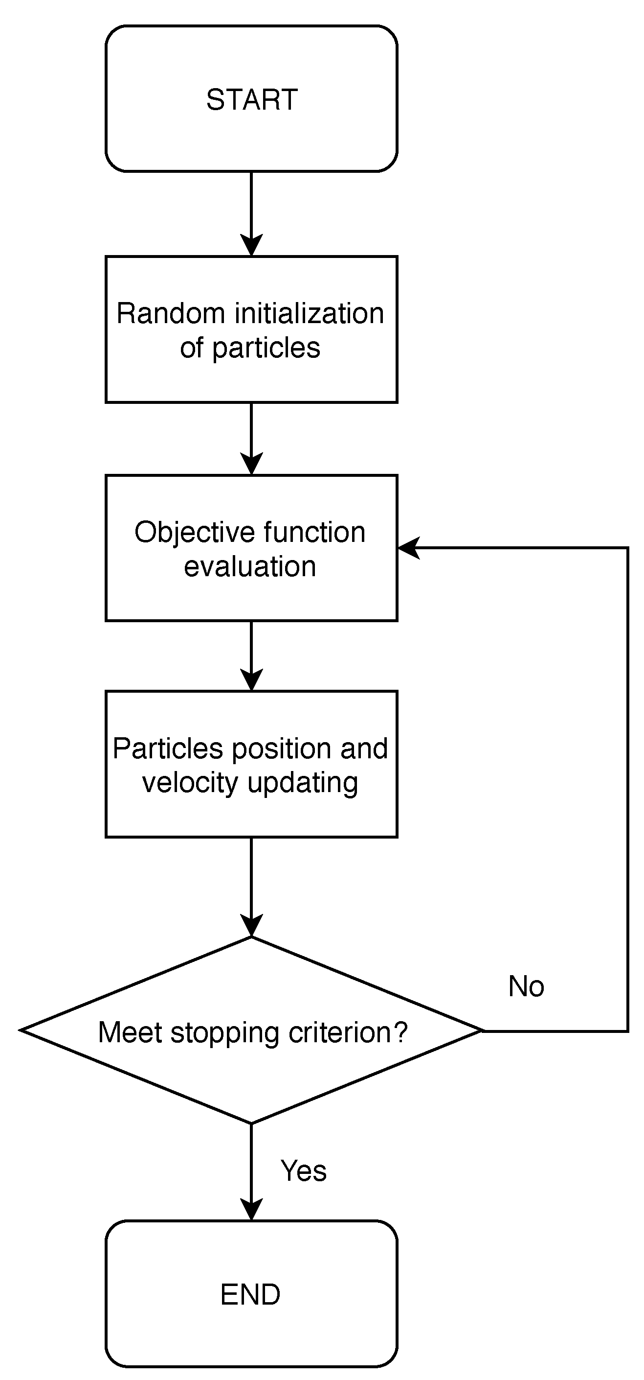
20], the authors proposed the EPFS for a HP (Hydrogen Peroxide)/PE (Polyethylene) upper stage, performing a deterministic optimization. In the present work, a robust-based design and optimization is performed considering EPFS with LOX/paraffin-based fuel. Only uncertainties in the classical regression rate correlation are taken into account. The authors use a combined procedure: an indirect method optimizes the trajectory for each combination of engine parameters [21,22] which, in turn, are selected by a particle swarm optimization algorithm [23]. The robust-based objective function is evaluated as a linear combination of an index that quantifies the effective reaching of the target orbit, based on the average performance under uncertainty, and the payload (that instead is not affected by uncertainties).
In the following sections, we sum up the main features of grain geometry, ballistic model, feed systems, and indirect optimization procedure. Then we compare the performance of gas-pressurized and pump feed systems, making our conclusions.

2. Numerical Models

2.1. Grain Geometry and Ballistic Model

In the present work, the authors considered LOX/paraffin-based fuel as propellant combination for HREs design. Cryogenic LOX is stored in liquid phase in a tank and injected into the combustion chamber during operation. The combustion chamber stores the wax in solid phase as a cylindrical grain. Paraffin-based fuels, such as wax, present an unstable melt liquid layer that causes the entrainment of droplets into the gas stream [24]. The fuel mass transfer rate into the flame zone is strongly increased by the entrainment of droplets. Combustion takes place in the flame zone through diffusive mixing of oxidizer and fuel coming from the grain. For this reason, regression rate is relatively large, and a single circular port can be adopted for the fuel grain, whereas classical fuels would require a multi-port grain design to avoid excessive length to diameter ratio (L/D) [25].
The grain outer radius R g , the web thickness w, and the grain length L b define the geometry of the circular-port grain as shown in Figure 1. The initial inner radius, i.e., the port radius before ignition, results to be R i = R g w . The burning perimeter P and the port area A p , for any given burning distance y ( 0 y w ), can be computed as:
P = 2 π R i + y
A p = π R i + y 2
An approximate relation, between chamber head-end pressure p 1 and chamber nozzle-stagnation pressure p c , is used to take into account pressure losses inside the combustion chamber [26]:
p 1 = 1 + 0.2 A t h A p 2 p c
where A t h is the throat area. The authors assumed a uniform regression rate along the port axis while the combustion of the lateral end is neglected. Its value is determined by the oxidizer mass flow rate m ˙ O and grain geometry:
y ˙ = a ( m ˙ O / A p ) n
In the present work a and n are assumed to be uncertain parameters. a = 9.1 × 10 5 m 2 n + 1 s n 1 kg n and n = 0.69 are taken into consideration as reference nominal values when International System (SI) of units are used [24].
The oxidizer flow rate is determined by the hydraulic resistance Z in the oxidizer flow path and the pressure provided by the feed system. Under the assumption of incompressible turbulent flow:
m ˙ O = ( p f s p 1 ) / Z
where p f s is the feed system pressure. We assume a constant value of Z during the operation. Fuel mass flow m ˙ F can be obtained as:
m ˙ F = ρ F y ˙ A b = ρ F y ˙ L b P
where ρ F is the fuel grain density, A b is the burning area. One can compute the mixture ratio α as:
α = m ˙ O m ˙ F m ˙ O 1 n A p n / A b
An isentropic expansion in the nozzle is assumed, and the chamber nozzle-stagnation pressure p c can be determined by:
p c = ( m ˙ O + m ˙ F ) c * A t h
The authors used a 10-bar chamber pressure in performance evaluation of the propellant combination as a function of the mixture ratio α . Even though the actual pressure in the combustion chamber can span over a wide range during engine operations, the performance error, due to the constant chamber pressure assumption, is small for pressures and mixture ratios considered in this article. Frozen equilibrium expansion is assumed: exhaust gas composition is fixed throughout the nozzle and equal to combustion chamber one. We adopt the conservative assumption of frozen equilibrium expansion to account for the low combustion efficiency of HREs. Moreover, a 0.96 c * -efficiency [27] is introduced. Third-degree polynomial curves, fitting the characteristic velocity and specific heat ratio, are embed in the code, to compute accurately and quickly the proper values as the mixture ratio changes during operation [28]. Thrust coefficient C F can be evaluated as:
C F = 0.98 2 γ 2 γ 1 2 γ + 1 γ + 1 γ 1 1 p e p c γ 1 γ + E p e p c E p 0 p c
where a 0.98 correction factor is introduced to modify the vacuum thrust coefficient of a 1-D isentropic expansion to the exit pressure p e with constant heat ratio γ . Atmospheric pressure-related term E · p 0 / p c is always small since the third stage always flies at high altitude. One can determine mass flow rate at ignition (i.e., at t = 0) as:
( m ˙ p ) i = ( 1 + α i ) ( m ˙ F ) i = 1 + α i α i ( m ˙ O ) i
Then initial throat area A t h i and initial port area A p i can be obtained:
( A t h ) i = ( m ˙ p ) i ( p c ) i c i * ; ( A p ) i = ( A t h ) i J
Nozzle throat erosion is here considered [29,30]. Bartz’s method is used to model the dependence of the rate of throat erosion s ˙ on throat radius R t h and chamber pressure p c :
s ˙ = s ˙ r e f p c p c , r e f 0.8 R t h , r e f R t h 0.2
R t h and E values are computed by integrating Equation (12). s ˙ r e f = 0.1 mm / s , obtained from CFD analysis on the ablation of a carbon/carbon nozzle for LOX/wax HREs [31], is here adopted. Our model does not consider erosion along the nozzle, obtaining a greater reduction of E and a conservative solution. Eroded mass is not taken into account, either for thrust augmentation or for rocket mass reduction.

2.2. Feed Systems

In the present work, the authors compare the performance of two different feed systems: a gas-pressurized feed system (GPFS) and an EPFS. During engine operation of a gas-pressurized feed system, the oxidizer mass flow rate is determined by the pressure drop between tank and chamber head-end pressures. The tank pressure is maintained constant by a pressurizing gas, contained in a high-pressure auxiliary tank during an initial regulated phase, which is then followed by a blow-down phase. The pressure at the pump outlet is instead considered in an EPFS. EPFS requires additional masses for batteries, electric motor, and pump while GPFS needs a heavier oxidizer tank, due to its higher pressure, and auxiliary gas and vessels. The performance of GPFS here considered, and put into comparison with EPFS, are taken from a previous optimization work by the authors [8]. Two sets of electrical properties for batteries and electric motor and pump are used in EPFS performance evaluation. Set A has already been employed by the authors, back in 2010, for the deterministic optimization of a HP/PE powered HRE [20]. Set B, instead, is taken from the most recent literature available [19].

2.2.1. GPFS

The GPFS has two operational modes. Initially, constant tank pressure is maintained by helium flowing from an auxiliary tank, thus p f s is constant too. Later, a subsequent blow-down (BD) phase is performed and p f s decreases during operation. The authors assume an initial ullage volume equal to 3% of the oxidizer volume to have a stable regulator response when the out flow starts [32]. The GPFS is characterized by two design parameters: the auxiliary gas tank volume V a and the initial pressurizing gas pressure p a . The exhausted oxidizer mass at the beginning of the BD phase m O B D is conveniently used instead of V a while the initial pressurizing gas pressure is kept constant at p a = 200 bar . During the constant pressure mode, p f s = p t i = 25 bar , whereas, during the BD phase, p f s is calculated assuming an isentropic expansion of the pressurizing gas in the tank:
p f s = ( p t ) i ( V g ) B D V g γ g
where the gas volume in the tank V g = V g i + m O / ρ O depends on the oxidizer mass m O that has been exhausted, V g B D = V g i + m O B D / ρ O and γ g is the specific heat ratio of the pressurizing gas.

2.2.2. EPFS

In the EPFS, an electric motor is used to drive the pump which feeds the oxidizer to the combustion chamber. A battery pack supplies the energy required by the electric motor during operation. Pump, electrical systems and batteries masses are evaluated by means of typical power density (power to mass ratio) values provided by existing literature. Thus, the electric motor and pump mass is evaluated as:
m e p = P e , m a x δ e p
where P e , m a x is the maximum electrical power required. In the following, two values for the power density δ e p has been assumed for the electric drive system plus pump: ( δ e p ) A = 1.25 kW/kg represents current technology [13,33] and ( δ e p ) B = 3.92 kW/kg for advances designs [19]. The electrical power required by the motor to drive the pump is:
P e = m ˙ O ( p f s p t ) ρ O η e p
where p f s is equal to the pump discharge pressure p d and p t is the oxidizer tank pressure. The tank pressure is assumed to be constant during operation and equal to 1 bar. The mass used to keep p t constant during operation is small and then can be neglected. The conversion of electrical energy, stored in the batteries, into flow head rise is taken into account by the overall efficiency η e p . In the present work, we assume two values for the overall efficiency, ( η e p ) A = 0.64 and ( η e p ) B = 0.53 . One can notice that ( η e p ) B < ( η e p ) A , but m e p ( δ e p · η e p ) 1 which is actually smaller for the newer Set B quantities. Battery pack mass is constrained by the most stringent requirement between the maximum electrical power required P e , m a x and the total electrical energy E e , t o t needed to drive the pump during the whole burning time. In the present case, the discharge time is equal to the overall HRE burning time t b u r n . Thus, the needed electrical energy is:
E e , t o t = 0 t b u r n P e d t
Batteries mass m b can be evaluated by means of typical values of power density δ b p and energy density δ b e (energy to mass ratio) that can be found in literature. A safety factor of 1.2 is assumed and therefore:
m b = 1.2 max P e , m a x δ b p , E e , t o t δ b e
Due to their small size and light weight compared to all other technologies, Lithium batteries, are considered for the present application. The authors considered two couples of densities to evaluate battery pack mass: ( δ b p ) A = 3.0 kW/kg and ( δ b e ) A = 90 Wh/kg, based on Ragone plots [34], and ( δ b p ) B = 6.95 kW/kg and ( δ b e ) B = 198.5 Wh/kg, based on state of the art Lithium-Polymer batteries [19]. These kinds of batteries are suitable for HRE applications because they require high power levels for a relatively short time, so that high rate capability is required. The pump is operated at constant power P e = P e , m a x . Thus, Equation (16) can be easily integrated and:
E e , t o t = P e , m a x t b u r n
The value of ( p d ) i at the beginning of the HRE operation is an additional parameter, used in the direct optimization procedure. It fixes the value of P e , m a x = P e = constant , which is crucial for feed system and engine performance.
One can notice that power-constrained batteries mass can be evaluated before the actual trajectory is optimized, while energy-constrained mass must be computed “a posteriori”. The authors define a characteristic burn time t b u r n * = δ b e / δ b p that represents the simultaneous fulfillment of both constraints. If t b u r n t b u r n * , power-constrained mass is larger than energy-constrained one. Hence, battery pack mass does not depend on the actual ascent trajectory. On the other hand, if t b u r n t b u r n * , energy-constrained mass is larger than power-constrained one. In this case, batteries mass must be checked “a posteriori” to take into account the additional energy required by a longer mission. Electric properties values are summarized in Table 1 for the sake of clarity.

2.3. Trajectory Optimization

Once engine design parameters have been defined, an indirect procedure optimizes the orbit insertion trajectory [21]. A point mass rocket is considered for the trajectory optimization. State equations provide the derivative of position r (radius, latitude and longitude), velocity v (radial, eastward and northward components) and rocket mass M. In a vectorial form one has:
d r d t = v d v d t = g + F D M d M d t = | F | c * C F
An inverse-square gravity field is assumed:
g = G M | | r 3 | | r
where G is the gravitational constant and M is Earth mass. An interpolation of the standard atmosphere, as a function of the rocket altitude, provides density and pressure evaluation. Equations of motion are written in a non-dimensional form to improve the accuracy of the numerical integration. Indirect optimization procedure details are here only summarized and can be found in Ref. [35].
An adjoint variable is associated with each equation; the theory of optimal control provides Euler-Lagrange equations, algebraic equations that determine the control variables (i.e., the thrust direction), and the boundary conditions for optimality (which also implicitly define the engine switching times). A Newton’s method-based procedure is used to solve the multi-point boundary value problem which arises. Further details about this procedure can be found in Ref. [36]. Tentative values are initially chosen for the problem unknowns and progressively modified to fulfill the boundary conditions. The unknown parameters are the time lengths of each phase and the initial values of five adjoint variables (the variable corresponding to longitude is null, the one corresponding to the mass is fixed at one, as the problem is homogeneous in the adjoint variables, which can therefore be arbitrarily scaled). Moreover, the overall oxidizer mass and the grain radius are additional unknowns. Dynamic pressure, heat flux and acceleration constraints are checked "a posteriori" and are not explicitly imposed during the trajectory optimization. However, the authors add a constraint that forces horizontal flight at the end of the first burn, to prevent the rocket from reentering the lower layers of the atmosphere (where the heat flux would become larger). Analogously, an additional unknown (the adjoint variable corresponding to the horizontal velocity component has a free discontinuity at the end of the first burn) is introduced in the trajectory optimization procedure.
In the present work, an HRE suitable for the replacement of third (solid) and fourth (liquid) stage of the Vega launcher is considered [37]. The performance of the first stage, second stage, and the exhausted masses are given. The conditions at the ignition of the third stage, consistent with a launch from Kourou, are assigned: altitude h = 86.88 km, latitude ϕ = 9.11 , velocity components in the radial, eastward and northward directions u r = 0.142 km/s, v e = 0.230 km/s, w n = 4.146 km/s, respectively, and mass m i = 14,522 kg [25]. Altitude, eccentricity and inclination (700 km, zero and 90 deg, respectively) define target final orbit. The longitude of the ascending node is left free.

2.4. Robust Design Model

Robust optimization problem can be formally cast as [10]:
find b R n to maximize Φ a v g b , p subject to g j b , p + z p 0 , j = 1 , , r and to b L b b U
where b is the design variables vector, p is the uncertain variables vector, z p is the noise vector of p, g j is the j-th inequality constraint, b L and b U are the lower and upper boundary of the design variables, respectively.
Here the initial mass of the upper stage is given at ignition and the hydraulic resistance Z is evaluated to have p t / p c = 2.5 at ignition in nominal condition. Six parameters are required to define the propulsion system: the grain outer radius R g , the web thickness w, the fuel grain length L b , the final exhausted oxidizer mass m O f and the initial nozzle area ratio E i . The sixth parameter is the exhausted oxidizer mass at the beginning of the BD phase m O B D , when GPFS is used, while the pump discharge pressure p d is needed when EPFS is considered. Therefore b G P F S = R g , w , L b , m O f , m O B D , E i and b E P F S = R g , w , L b , m O f , p d , E i . Upper and lower boundary of the design variables for GPFS and EPFS are shown in Table 2 and Table 3 respectively.
Uncertain parameters are the regression rate coefficients a and n, i.e., p = a , n . Uncertainties are taken into account assigning three different levels for each uncertain variables: a i × 10 5 = 9 , 9.1 , 9.2 m 2 n + 1 s n 1 kg n for i = 1 , 2 , 3 , respectively, and n j = 0.68 , 0.69 , 0.7 for j = 1 , 2 , 3 , respectively. The altitude of the attained orbit h i j is evaluated for each of the nine possible couples a i , n j . Since two objectives are relevant (i.e., payload μ and altitude h), an ϵ -constraint approach is adopted [38] to find the Pareto front of robust solutions. Here only the average performance is analyzed. The average constraint violation Δ a v g = i j p i p j max i j ( 0 , h * h i j ) is considered. We assume a binomial distribution giving p 1 = p 3 = 0.25 and p 2 = 0.5 . The average altitude is then h a v g = h * Δ a v g and the objective function can be computed as:
Φ a v g = μ k max ( 0 , ϵ h a v g )
k = 20 kg / km is selected to force the average altitude at ϵ . Only the case ϵ = h * = 700 km (that is the most demanding in terms of robustness) is here considered.
The selection of the optimal robust design is performed by means of a particle swarm optimization (PSO) algorithm. PSO is an optimization procedure belonging to the class of evolutionary algorithms (EAs) that search for an optimal solution in a prescribed search space. It is inspired by the social behavior showed by flock of birds and school of fishes [39,40]. Solutions, here called particles, fly through the problem space by following the optimum particle (i.e., the alpha-member of the flock or school). Cognitive and social acceleration drive the motion of each particle and their position and speed are updated at each iteration. Basic steps of PSO are shown in Figure 2 and PSO settings are presented in Table 4. Additional details about PSO implementation and tuning can be found in Refs. [23,41].

3. Numerical Results

As described in the previous sections, a two-layer optimization is employed for trajectory and engine design: the indirect trajectory optimization maximizes the final mass given engine geometry, which, in turn, is optimized by means of a robust-based design approach. The average height violation Δ a v g is forced to zero, due to the large value for k in Equation (22), and Φ coincides with the payload for all the robust designs summarized in Table 5. Please note that the final burn of the HRE has a very short duration and a limited influence on the rocket performance. Hence subsequent figures show only the first burn for the sake of simplicity.
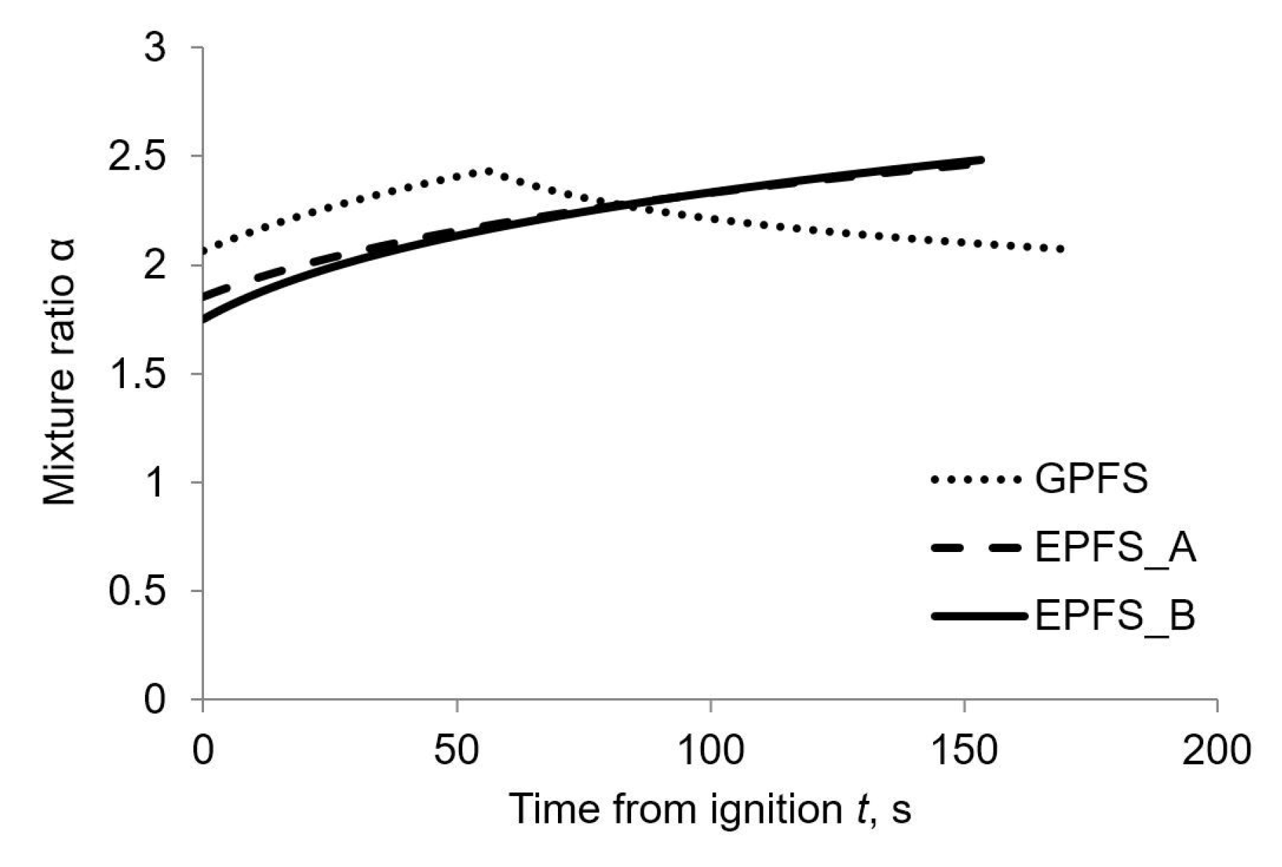
When pump feed system is adopted, mixture ratio and regression rate tend to be larger at the end of the engine burn with respect to GPFS values, as shown in Figure 3 and Figure 4 respectively.
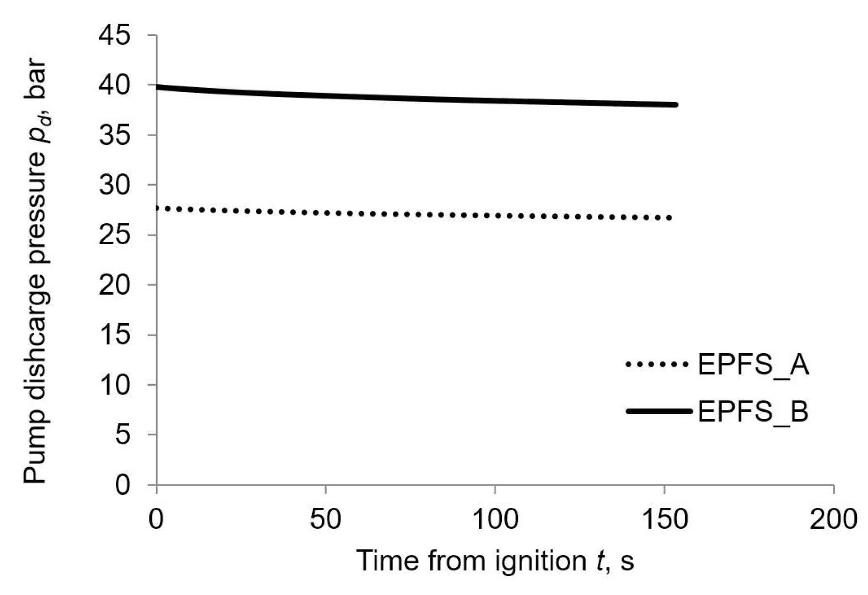
 Figure 5 and Figure 6 display that pump discharge pressure and oxidizer mass flow variations are actually limited (less than 5%), due to pump constant power operation during the engine burn. Hence efficiency and electrical density assumption for the electric motor and pump system are valid. Thrust history and longitudinal acceleration exhibit different behavior for GPFS and EPFS as reported in Figure 7 and Figure 8 respectively.
The thrust in the first half of the burn is larger for the GPFS, with respect to EPFS one, to maintain an acceptable thrust level during the subsequent BD phase. On the other hand, EPFS can maintain an almost constant thrust for all the burn duration and thus its initial thrust level can be lower than GPFS one.
One can notice that EPFS A and EPFS B have almost the same thrust history. Nevertheless, the thrust level is obtained in two different ways: EPFS A optimal design is characterized by lower discharge pressure (i.e., low chamber pressure) and a larger nozzle (i.e., large throat area) than EPFS B ones. This behavior is forced by the low electric motor and pump power density ( δ e p ) A that penalizes high-pressure designs. On the other hand, EPFS B optimal design favors a higher discharge, and thus chamber, pressures alongside a smaller and lighter nozzle (i.e., small throat area) than EPFS A ones. The latter optimization strategy is allowed by the advanced electrical properties considered in set B and grants a remarkable nozzle mass saving without thrust reduction.
Mass budgets for robust solutions are reported in Table 6 whereas normalized mass ratios are summarized in Table 7. The current Vega configuration payload for the mission considered in the present work is equal to 1500 kg [37]. The main sources of performance improvement, for both GPFS and EPFS designs, are a remarkable saving in the dry masses of the upper stages and reduced Δ v losses. Furthermore, one can notice that EPFS A saves roughly 350 kg due to lighter tank (pumps allow for unpressurized oxidizer tank), smaller nozzle, and far lower pressurizing gas mass than GPFS one. Moreover, EPFS does not require the auxiliary tank. Thus, the total mass saving is close to 500 kg with respect to GPFS. On the other hand, EPFS requires electric motor and batteries masses that are equal to roughly 230 kg for EPFS A and 150 kg for EPFS B . Hence, the payload gain when EPFS is considered, with respect to GPFS, is equal to 252 kg and 398 kg when current or advanced technologies are considered in electric motor and pump masses evaluation. EPFS B motor, pump and batteries masses are smaller than EPFS A ones due to better electrical properties despite an actually larger electric power consumption (i.e., higher initial discharge pressure) and electric energy requirement.

4. Conclusions

An indirect trajectory optimization procedure coupled with an evolutionary algorithm has been used to assess the performance viability of an electrically driven pump-fed HRE. The performance of EPFS have been compared to GPFS ones. The optimization of an upper stage of a Vega-like launcher has been considered. The optimization is performed for a given insertion orbit and lift-off weight. The authors take into account uncertainties in the regression rate to grant robustness of the optimal solution. A linear combination of average altitude and payload has been used as mission-specific performance index. The solution is forced to nullify the spread of the orbit altitude by the chosen index formulation, thus assuring the required robustness.
Results show that electric pumps are a viable option for the replacement of a GPFS for the present application. Present technology in batteries and electric motor allows for a payload improvement of approximately 250 kg with respect to GPFS, granting the same level of robustness. A further payload gain is achieved when advanced batteries are considered. Pump power control law can be taken into consideration in future works to improve engine performance and reduce electrical systems masses and maximum longitudinal acceleration.

Author Contributions

Conceptualization, L.C. and D.P.; Data curation, F.M.; Formal analysis, L.C., F.M. and D.P.; Methodology, L.C., F.M. and D.P.; Software, L.C., F.M. and D.P.; Supervision, L.C. and D.P.; Writing—original draft, F.M.; Writing—review & editing, L.C., F.M. and D.P.

Funding

This research received no external funding.

Conflicts of Interest

The authors declare no conflict of interest.

Abbreviations

The following abbreviations are used in this manuscript:
BDBlow-Down
CFDComputational Fluid Dynamics
EA(s)Evolutionary Algorithm(s)
EPFSElectric Pump Feed System
GPFSGas-Pressurized Feed System
HPHydrogen Peroxide
HRE(s)Hybrid Rocket Engine(s)
LOXLiquid-Oxygen
LRE(s)Liquid Rocket Engine(s)
MAVMars Ascent Vehicle
PEPolyethylene
PSOParticle Swarm Optimization
RP1Rocket Propellant 1
SIInternational System of units
SRM(s)Solid Rocket Motor(s)
SSOSingle Stage to Orbit
Nomenclature
A b burning surface area, m 2
A p port area, m 2
A t h nozzle throat area, m 2
aregression constant, m 1 + 2 n kg n s n 1
bdesign variables vector
b L lower bound vector
b U upper bound vector
C F thrust coefficient
c * characteristic velocity, m/s
D drag vector, N
Drocket outer diameter, m
Enozzle area ratio
E e electric energy, Wh
F thrust vector, N
Fthrust, N
Ggravitational constant, Nm 2 /kg 2
g gravity acceleration, m/s 2
g j b j-th inequality constraint
haltitude, km
h * target altitude, km
I S P mean specific impulse, s
I ρ density-specific impulse, kg s/m 3
Jthroat area to initial port area ratio
klinear combination constant, kg/km
Loverall engine length, m
L b fuel grain length, m
Mrocket mass, kg
M Earth mass, kg
mmass, kg
Nnumber
nmass-flux exponent
Pburning perimeter, m
P e electric power, kW
puncertain variables vector
ppressure, bar
R g grain outer radius, m
R i grain initial inner radius, m
R t h throat radius, m
r position vector, m
seroded distance, mm
ttime, s
u r velocity component in the radial direction, km/s
Vvolume, m 3
v e velocity component in the eastward direction, km/s
v velocity vector, m/s
v m a x maximum particle velocity vector in PSO
wweb thickness, m
w n velocity component in the northward direction, km/s
yburning distance, m
Zhydraulic resistance, 1/(kg m)
z p noise vector of p
α mixture ratio
γ specific heat ratio
δ e p electric motor and pump power density, kW/kg
δ b e batteries energy density, Wh/kg
δ b p batteries power density, kW/kg
Δ altitude violation, m
ϵ multi-objective constraint, km
η e p electric motor and pump efficiency
μ payload, kg
ρ density, kg/m 3
Φ objective function, kg
ϕ latitude, deg
Superscripts
˙ time derivative
*characteristic
Subscripts
0ambient
1combustion chamber at head-end
Aset A electric properties
aauxiliary gas
a v g average
Bset B electric properties
B D beginning of blow-down phase
bbatteries
b u r n engine burn
ccombustion chamber at nozzle entrance
c c combustion chamber
ddischarge
d r y dry
enozzle exit
e p electric motor and pump
Ffuel
ffinal
f s feed system
Ggenerations
gpressurizing gas
Iindividuals
iinitial value
m a x maximum
n z nozzle
Ooxidizer
poverall propellant (oxidizer + fuel)
r e f reference
s l sliver
toxidizer propellant tank
t h throat
t o t total

References

  1. Casalino, L.; Pastrone, D. Optimal design of hybrid rocket motors for microgravity platform. J. Propuls. Power 2008, 24, 491–498. [Google Scholar] [CrossRef]
  2. Jens, E.; Karp, A.C.; Nakazono, B.; Eldred, D.B.; DeVost, M.E.; Vaughan, D. Design of a Hybrid CubeSat Orbit Insertion Motor. In Proceedings of the 52nd AIAA/SAE/ASEE Joint Propulsion Conference, AIAA Propulsion and Energy Forum, Salt Lake City, UT, USA, 25–27 July 2016. [Google Scholar]
  3. Dornheim, M.A. Reaching 100 km. AW & ST 2004, 161, 45–46. [Google Scholar]
  4. Casalino, L.; Pastrone, D. Optimization of Hybrid Sounding Rockets for Hypersonic Testing. J. Propuls. Power 2012, 28, 405–411. [Google Scholar] [CrossRef]
  5. Karp, A.C.; Nakazono, B.; Manrique, J.B.; Shotwell, R.; Vaughan, D.; Story, G.T. A Hybrid Mars Ascent Vehicle Concept for Low Temperature Storage and Operation. In Proceedings of the 52nd AIAA/SAE/ASEE Joint Propulsion Conference, AIAA Propulsion and Energy Forum, Salt Lake City, UT, USA, 25–27 July 2016. [Google Scholar]
  6. Pastrone, D. Approaches to Low Fuel Regression Rate in Hybrid Rocket Engines. IJAE 2012, 2012. [Google Scholar] [CrossRef]
  7. Casalino, L.; Pastrone, D. A Straightforward Approach for Robust Design of Hybrid Rocket Engine Upper Stage. In Proceedings of the 51st AIAA/SAE/ASEE Joint Propulsion Conference, AIAA Propulsion and Energy Forum, Orlando, FL, USA, 27–29 July 2015. [Google Scholar] [CrossRef]
  8. Casalino, L.; Masseni, F.; Pastrone, D. Comparison of Robust Design Approaches for Hybrid Rocket Engines. In Proceedings of the 53rd AIAA/SAE/ASEE Joint Propulsion Conference, AIAA Propulsion and Energy Forum, Atlanta, GA, USA, 10–12 July 2017. [Google Scholar] [CrossRef]
  9. Taguchi, G.; Chowdhury, S.; Taguchi, S. Robust Engineering; McGraw-Hill: New York, NY, USA, 2000; ISBN 978-0071347822. [Google Scholar]
  10. Park, G.J.; Lee, T.H.; Lee, K.H.; Hwang, K.H. Robust Design: An Overview. AIAA J. 2006, 44, 181–191. [Google Scholar] [CrossRef]
  11. Johnsson, G.; Bigert, M. Development of Small Centrifugal Pumps for an Electric Propellant Pump System. Acta Astronaut. 1990, 21, 429–438. [Google Scholar] [CrossRef]
  12. Schneider, S.J. Low thrust chemical rocket technology. In Proceedings of the 43rd Congress of the International Astronautical Federation, Washington, DC, USA, 28 August–5 September 1992. [Google Scholar]
  13. Abel, T.M.; Velez, T.A. Electrical Drive System for Rocket Engine Propellant Pumps. U.S. Patent 6457306B1, 1 October 2002. [Google Scholar]
  14. Soldà, N.; Lentini, D. Opportunities for a Liquid Rocket Feed System Based on Electric Pumps. J. Propuls. Power 2008, 24, 1340–1346. [Google Scholar] [CrossRef]
  15. Pavlov Rachov, P.A.; Tacca, H.; Lentini, D. Electric Feed Systems for Liquid-Propellant Rockets. J. Propuls. Power 2013, 29, 1171–1180. [Google Scholar] [CrossRef]
  16. Bahn, P.R.E. Rocket Engine Systems. U.S. Patent 9677503B2, 13 June 2017. [Google Scholar]
  17. Vaughan, D.; Nakazono, B.; London, A.; Mehra, A. Technology Development of an Electrically Driven Pump Fed Storable Liquid Bi-Propellant for a Mars Ascent Vehicle. In Proceedings of the 68th International Astronautical Congress, Adelaide, Australia, 25–29 September 2017. [Google Scholar]
  18. Waxenegger-Wilfing, G.; Hahn, R.H.S.; Deeken, J. Studies on Electric Pump-Fed Liquid Rocket Engines for Micro-Launchers. In Proceedings of the Space Propulsion Conference, Seville, Spain, 14–18 May 2018. [Google Scholar]
  19. Kwak, H.D.; Kwon, S.; Choi, C.H. Performance Assessment of Electrically Driven Pump-Fed LOX/Kerosene Cycle Rocket Engine: Comparison with Gas Generator Cycle. Aerosp. Sci. Technol. 2018, 77, 67–82. [Google Scholar] [CrossRef]
  20. Casalino, L.; Pastrone, D. Optimization of a Hybrid Rocket Upper Stage with Electric Pump Feed System. In Proceedings of the 46th AIAA/ASME/SAE/ASEE Joint Propulsion Conference and Exhibit, Nashville, TN, USA, 25–28 July 2010. [Google Scholar]
  21. Casalino, L.; Colasurdo, G.; Pastrone, D. Optimal Low-Thrust Escape Trajectories Using Gravity Assist. J. Guid. Control Dyn. 1999, 22, 637–642. [Google Scholar] [CrossRef]
  22. Casalino, L.; Pastrone, D. Oxidizer Control and Optimal Design of Hybrid Rockets for Small Satellites. J. Propuls. Power 2005, 21, 230–238. [Google Scholar] [CrossRef]
  23. Sentinella, M.R.; Casalino, L. Hybrid Evolutionary Algorithm for the Optimization of Interplanetary Trajectories. J. Spacecr Rocket. 2009, 46, 365–372. [Google Scholar] [CrossRef]
  24. Karabeyoglu, M.A.; Altman, D.; Cantwell, B.J. Combustion of Liquefying Hybrid Propellants: Part 1, General Theory. J. Propuls. Power 2002, 18, 610–620. [Google Scholar] [CrossRef]
  25. Casalino, L.; Pastrone, D. Optimal Robust Design of Hybrid Rocket Engines. In Springer Optimization and Its Applications; Springer: New York, NY, USA, 2016; Volume 114, pp. 269–285. ISBN 978-3-319-41506-2. [Google Scholar]
  26. Barrere, M.; Jaumotte, A.; De Veubeke, B.F.; Vandenkerckhove, J. Rocket Propulsion; Elsevier Publishing Company: Amsterdam, The Netherlands, 1960; pp. 251–256. ISBN B0000CKFWU. [Google Scholar]
  27. Sutton, G.P.; Biblarz, O. Rocket Propulsion Elements, 7th ed.; Wiley: New York, NY, USA, 2001; ISBN 978-0471326427. [Google Scholar]
  28. Mc Bride, B.J.; Reno, M.A.; Gordon, S. CET93 and CETPC: An Interim Updated Version of the NASA Lewis Computer Program for Calculating Complex Chemical Equilibria with Applications; TM-4557; NASA: Cleveland, OH, USA, 1994.
  29. Casalino, L.; Letizia, F.; Pastrone, D. Optimization of Hybrid Upper-Stage Motor with Coupled Evolutionary/Indirect Procedure. J. Propuls. Power 2014, 30, 1390–1398. [Google Scholar] [CrossRef]
  30. Ellis, R.A. Solid Rocket Motor Nozzles—NASA Space Vehicle Design Criteria (Chemical Propulsion); SP-8115; NASA: Cleveland, OH, USA, 1975.
  31. Bianchi, D.; Nasuti, F. Numerical Analysis of Nozzle Material Thermochemical Erosion in Hybrid Rocket Engines. J. Propuls. Power 2013, 29, 547–558. [Google Scholar] [CrossRef]
  32. Brown, C.D. Spacecraft Propulsion; AIAA Education Series: Washington, DC, USA, 1992; p. 82. [Google Scholar]
  33. NASA Lewis Research Center. Turbopump Systems for Liquid Rocket Engines; SP-8107; NASA: Cleveland, OH, USA, 1974.
  34. Battery and Energy Technologies. Available online: http://www.mpoweruk.com/performance.htm (accessed on 1 June 2010).
  35. Casalino, L.; Pastrone, D. Optimal Design and Control of Hybrid Rockets for Access to Space. In Proceedings of the 41st AIAA/ASME/SAE/ASEE Joint Propulsion Conference & Exhibit, Joint Propulsion Conferences, Tucson, AZ, USA, 10–13 July 2005. [Google Scholar] [CrossRef]
  36. Colasurdo, G.; Pastrone, D. Indirect Optimization Method for Impulsive Transfer. In Proceedings of the Astrodynamics Conference, Guidance, Navigation, and Control and Co-located Conferences, Scottsdale, AZ, USA, 1–3 August 1994. [Google Scholar] [CrossRef]
  37. Isakowitz, S.J.; Hopkins, J.A.; Hopkins, J.A., Jr. International Reference Guide to Space Launch Systems, 4th ed.; AIAA: Portland, OR, USA, 2004; pp. 517–524. [Google Scholar]
  38. Haimes, Y.; Lasdon, L.; Wismer, D. On a Bicriterion Formulation of the Problems of Integrated System Identification and System Optimization. IEEE Trans. Syst. Man Cybern. 1971, SMC-1, 296–297. [Google Scholar] [CrossRef]
  39. Eberhart, R.; Kennedy, J. Particle Swarm Optimization. In Proceedings of the IEEE International Conference on Neural Networks, Perth, Australia, 27 November–1 December 1995; pp. 1942–1948. [Google Scholar] [CrossRef]
  40. Eberhart, R.; Kennedy, J. A New Optimizer Using Particle Swarm Theory. In Proceedings of the Sixth International Symposium on Micro Machine and Human Science, Nagoya, Japan, 6 August 2002; pp. 39–43. [Google Scholar] [CrossRef]
  41. Sentinella, M.R. Development of New Procedures and Hybrid Algorithms for Space Trajectories Optimisation. Ph.D. Thesis, Politecnico di Torino, Turin, Italy, March 2008. [Google Scholar]
Figure 1. Schematic of the grain geometry.
Aerospace 06 00036 g001
Figure 2. PSO: flow chart.
Aerospace 06 00036 g002
Figure 3. Mixture ratio history.
Aerospace 06 00036 g003
Figure 4. Regression rate history.
Aerospace 06 00036 g004
Figure 5. Discharge pressure history.
Aerospace 06 00036 g005
Figure 6. Oxidizer mass flow history.
Aerospace 06 00036 g006
Figure 7. Thrust history.
Aerospace 06 00036 g007
Figure 8. Longitudinal acceleration history.
Aerospace 06 00036 g008
Table 1. Electric properties.
Design Set δ bp kW/kg δ be kW/kg δ ep kW/kg η ep - t burn * s
A3.0090.001.250.68108
B6.95198.503.920.53103
Table 2. Design parameters ranges: GPFS.
Boundary R g w L b m O f m O B D E i
mmmkgkg-
b L 0.550.254.36971319515
b U 0.600.354.57697363120
Table 3. Design parameters ranges: EPFS.
Boundary R g w L b m O f p d E i
mmmkgbar-
b L 0.550.254.369711015
b U 0.600.354.576975020
Table 4. PSO settings.
ParameterValue
Number of generations, N G 100
Number of particles, N I 20
Dimension of particles6
Ranges of particles b U b L
PSO method1-trelea type 1
Cognitive acceleration, C 1 2.0
Social acceleration, C 2 2.0
Check population methodSaturation
End velocity weight0.4
Linear varying factor0.2
Maximum velocity, v m a x 0.25 ( b U b L )
Mass mutation parameter98%
Table 5. Design parameters and performance.
Case R g w L b m O f E i m O B D p d μ Δ a v g Φ a v g t b u r n I S P
mmmkg-kgbarkgkmkgss
GPFS0.5910.2944.360740317.323195-2069.80.02069.8177296
EPFS A 0.5790.3034.438740817.44-27.72321.70.02321.7157296
EPFS B 0.5630.3344.368738118.14-39.82467.70.02467.7158296
Table 6. Mass budget comparison.
Case μ m O m F m s l m c c m t m n z m c a s e m g m a m b m e p
kgkgkgkgkgkgkgkgkgkgkgkg
GPFS2069.87403.53364.00.00160.2299.4351.1165.623.6149.8--
EPFS A 2321.77407.73392.40.00147.412.0309.7163.70.0315-98.0134.4
EPFS B 2467.77380.53414.60.00162.312.0239.7158.40.0314-77.374.4
Table 7. Mass budget comparison: normalized ratios.
Case μ m i m p m i m p m p + m d r y
---
GPFS0.1430.7410.904
EPFS A 0.1600.7440.926
EPFS B 0.1700.7430.937

