Simulation and Test of Discrete Mobile Surfaces for a RC-Aircraft


Abstract
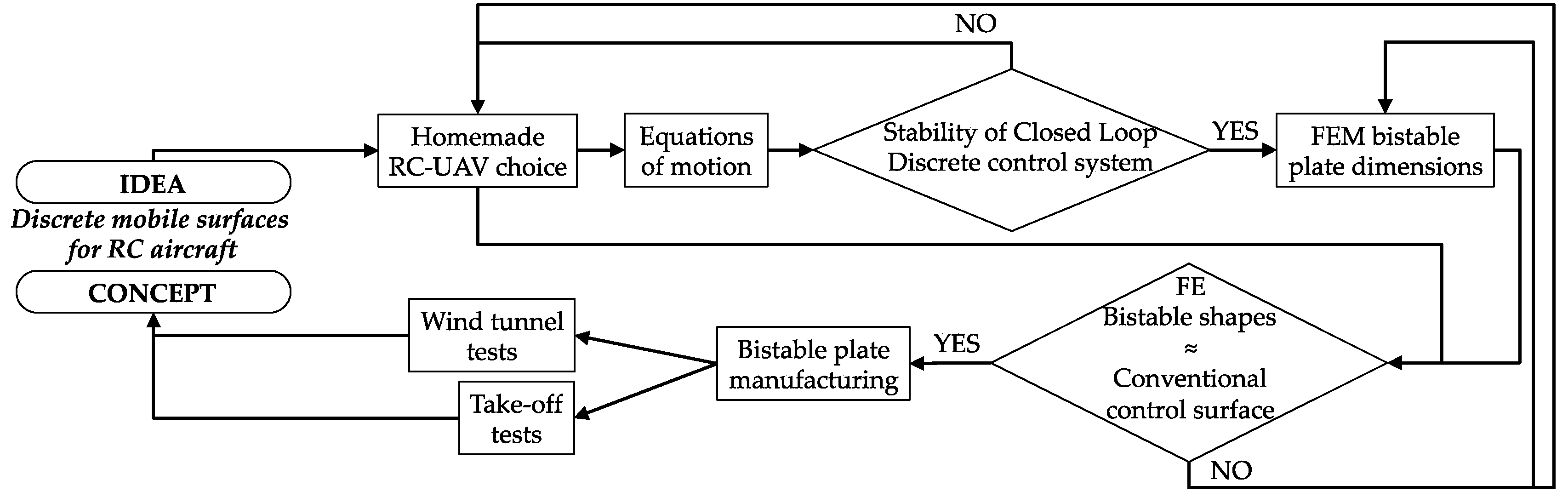
1. Introduction
2. Models, Materials and Methods
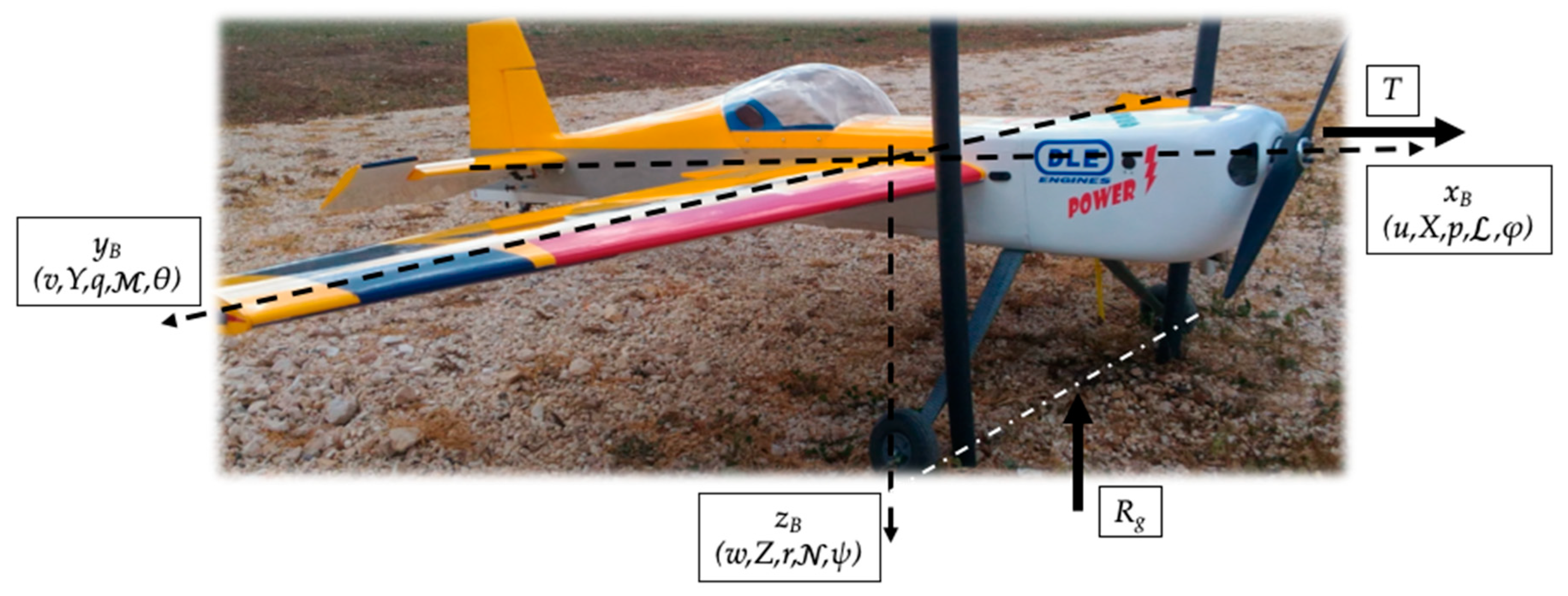
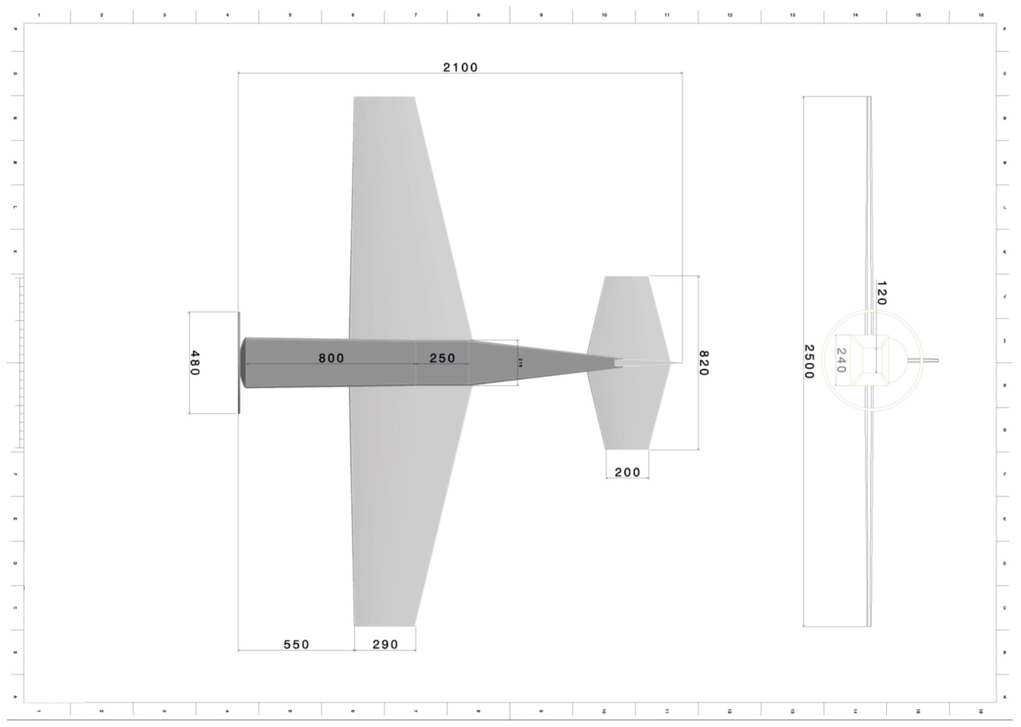
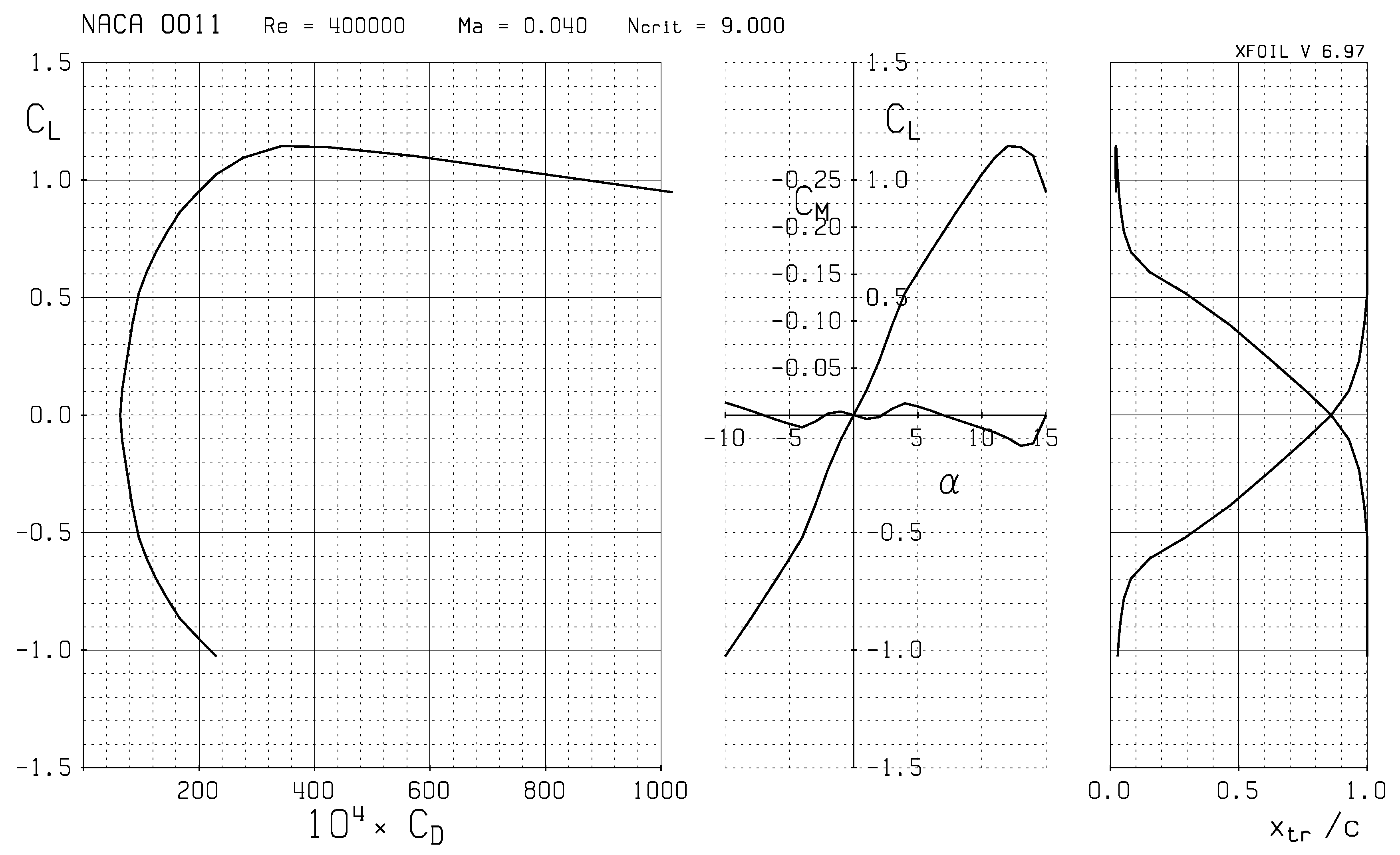
2.1. Flight Dynamics Equations and UAV Features
- Dynamics of the centre of mass:
- Attitude dynamics:
- Attitude kinematics:
- Trajectory of the centre of mass:
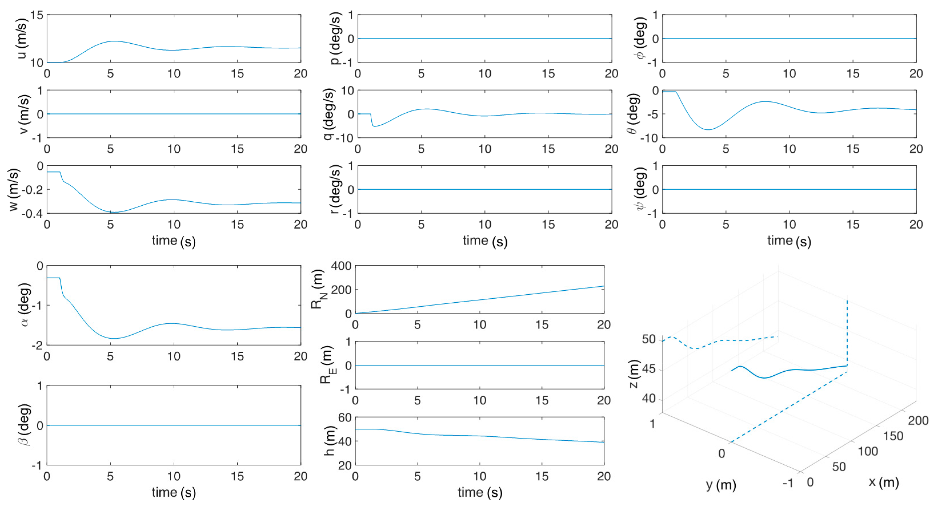
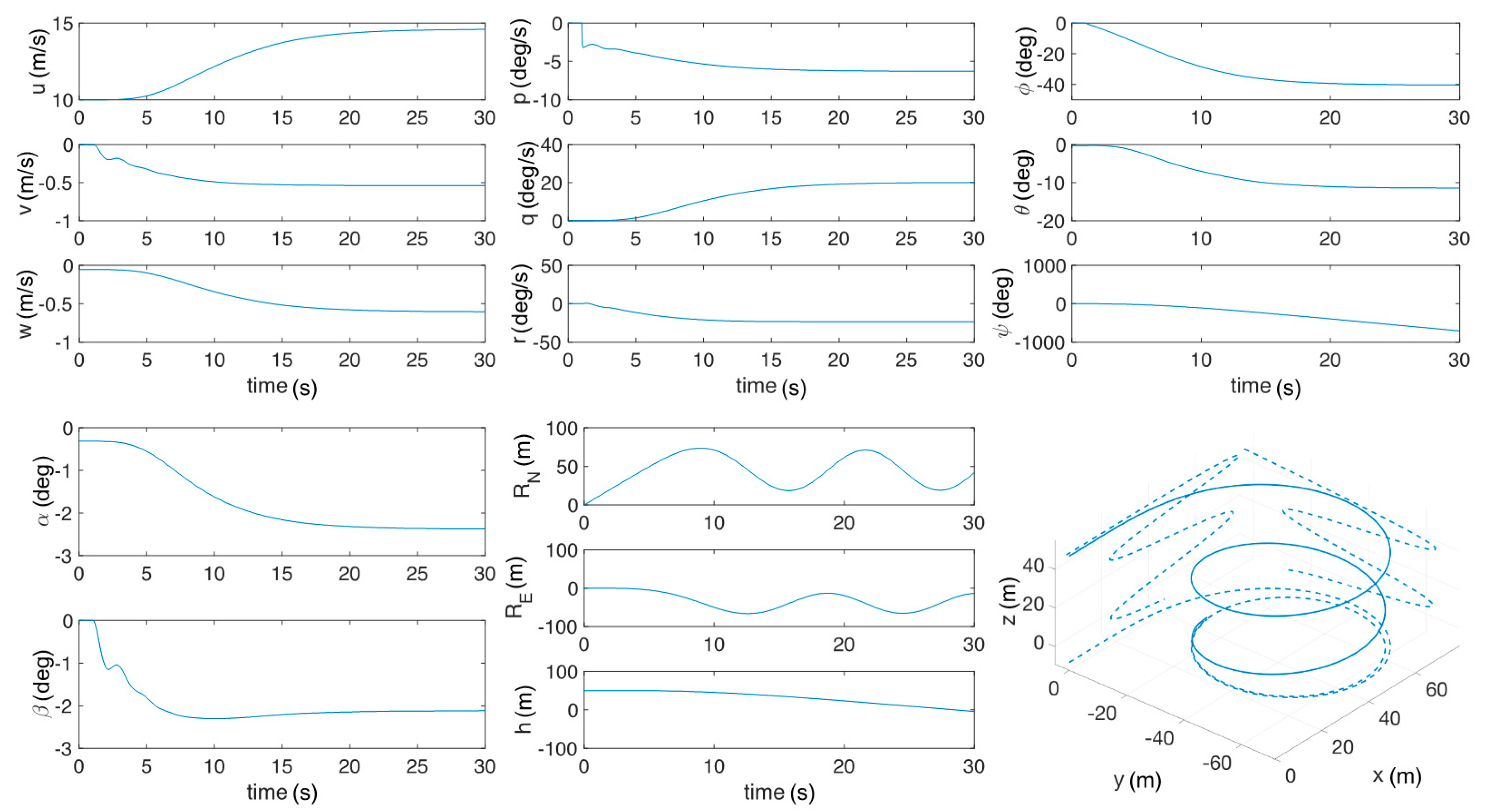
- Open-loop simulations by applying a specific command input to the elevator, ailerons and rudder: the command consisted in a 1 degree positive step;
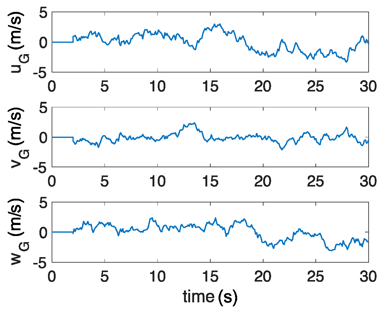
- Closed-loop simulations (gust response by using Dryden wind turbulence model) with a full-state feedback control by means of the linear quadratic regulator (LQR) method;
- Take-off length simulations.
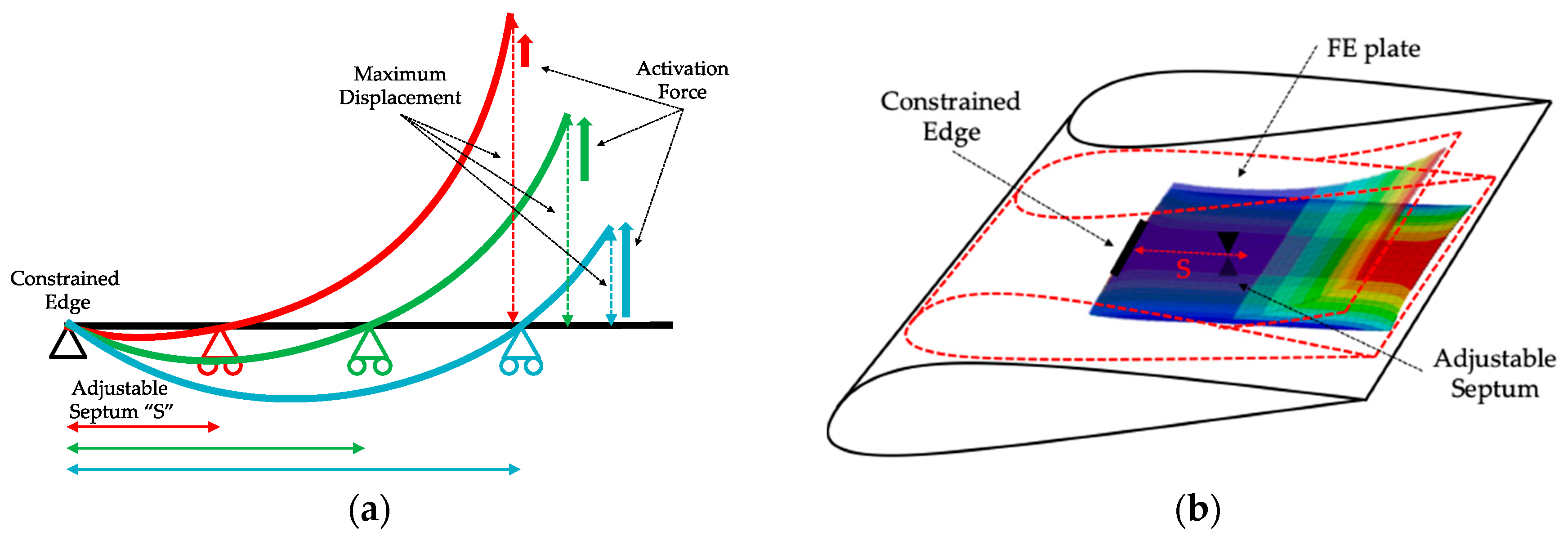
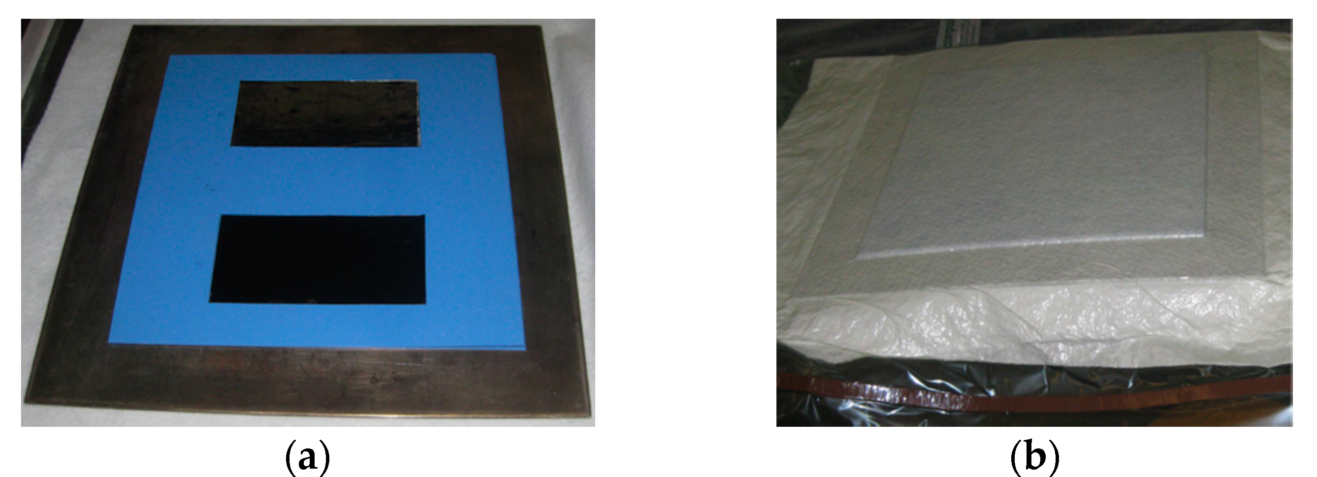
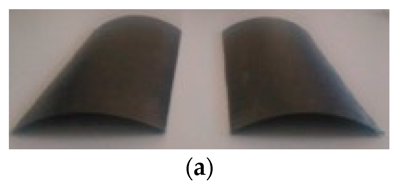
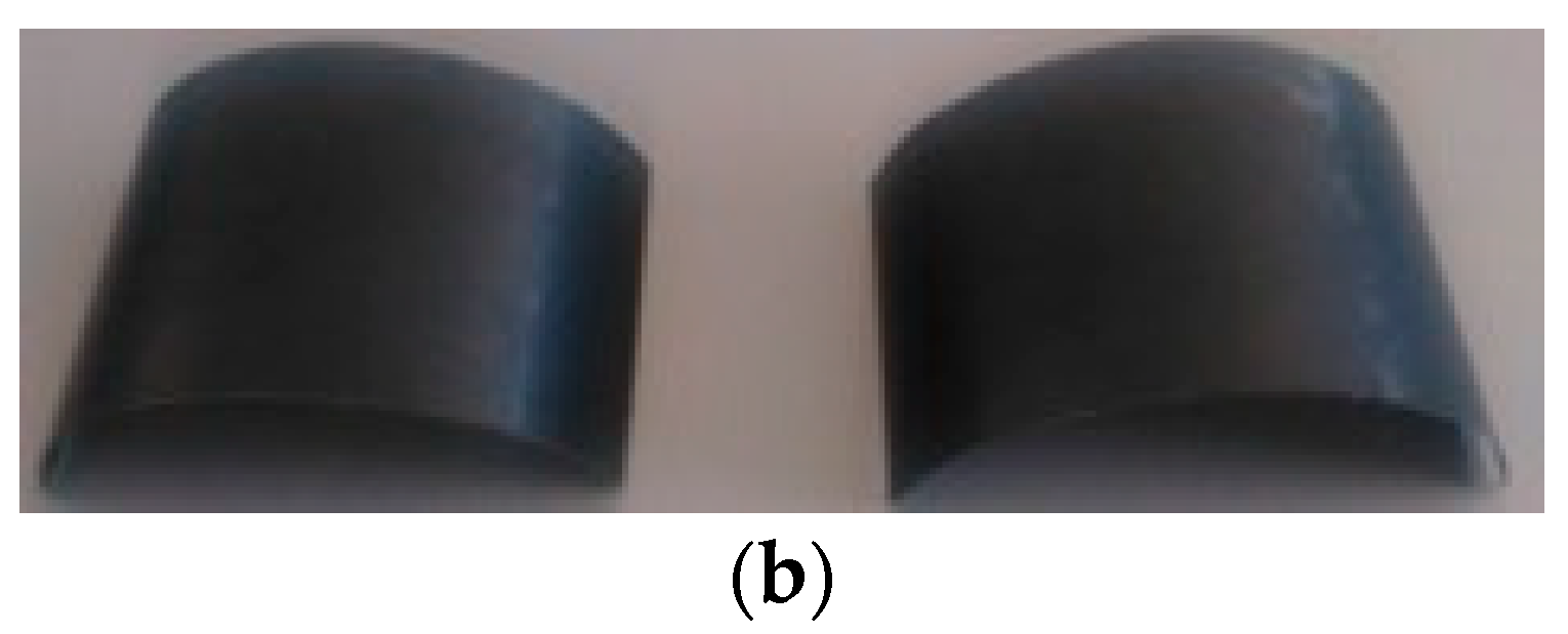
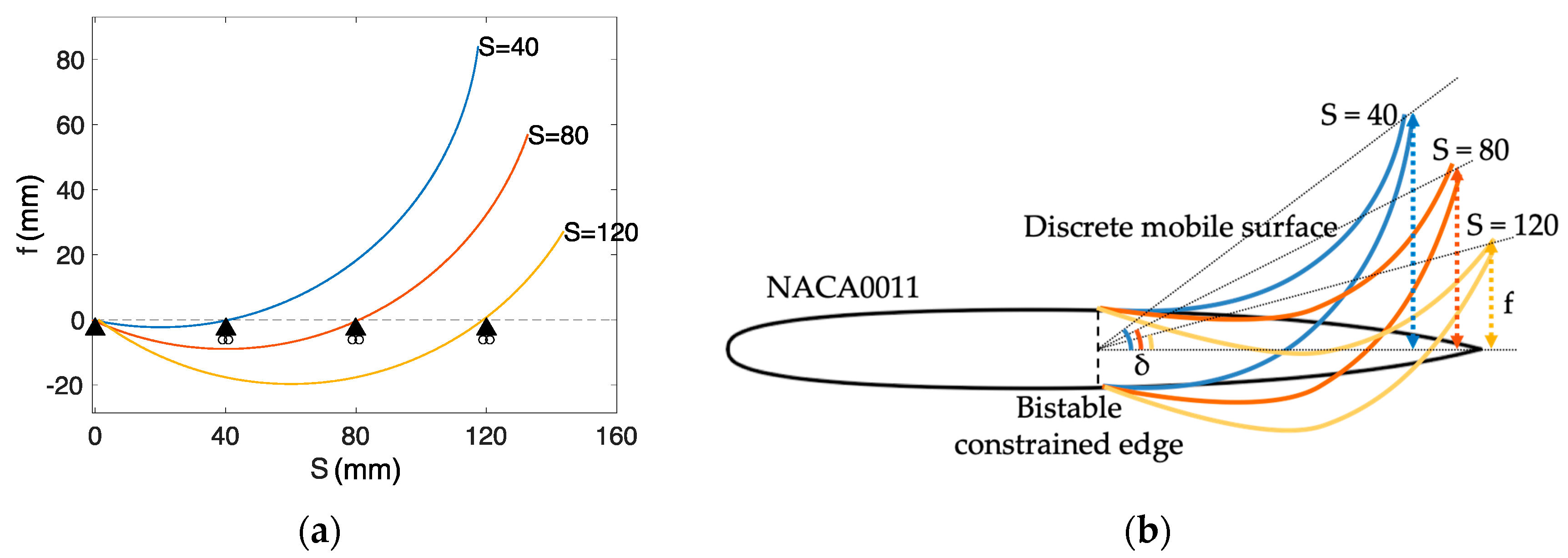
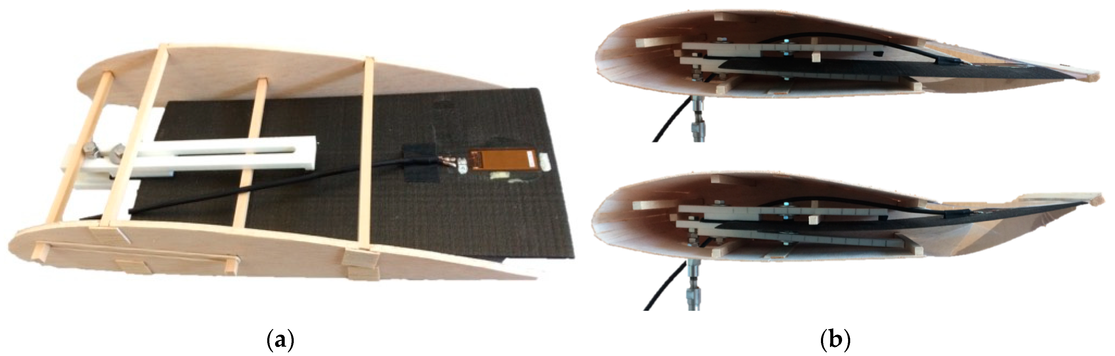
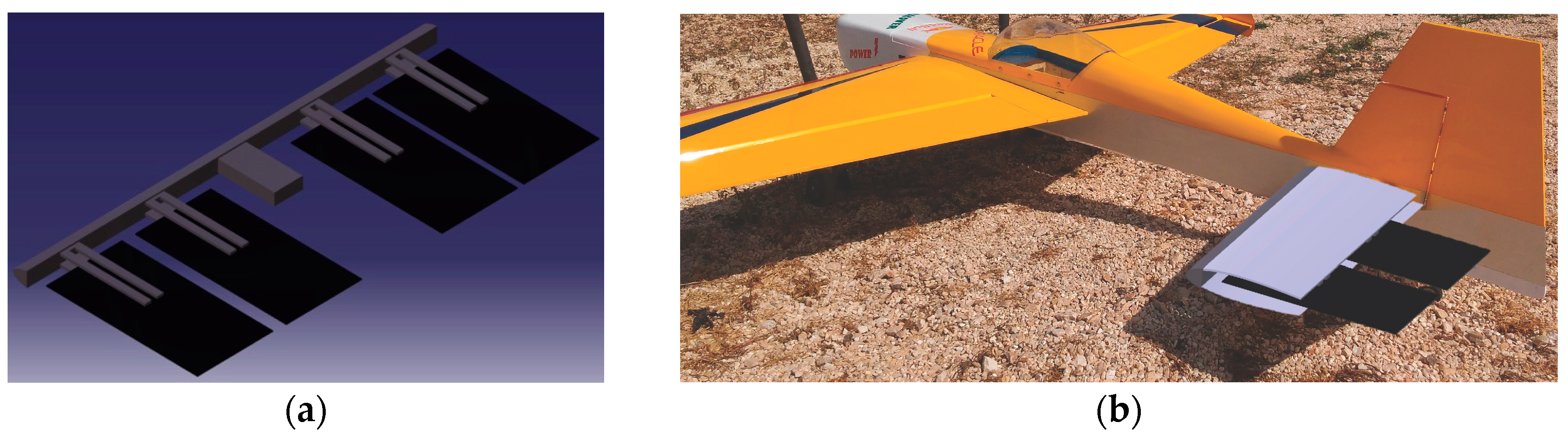
2.2. FE Simulations and Manufacturing of Bistable Plates
3. Results and Discussion
3.1. Simulink Results
3.1.1. Open-Loop Simulations
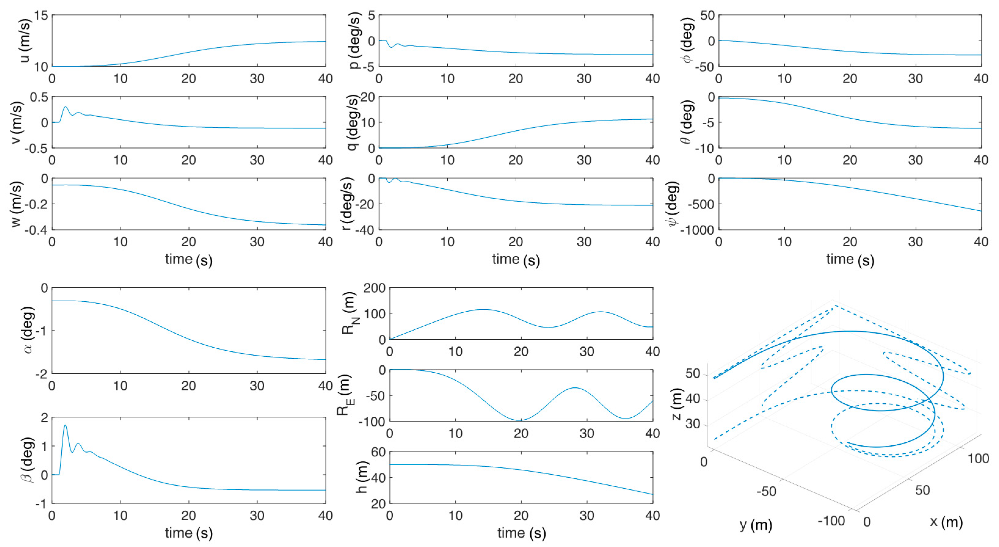
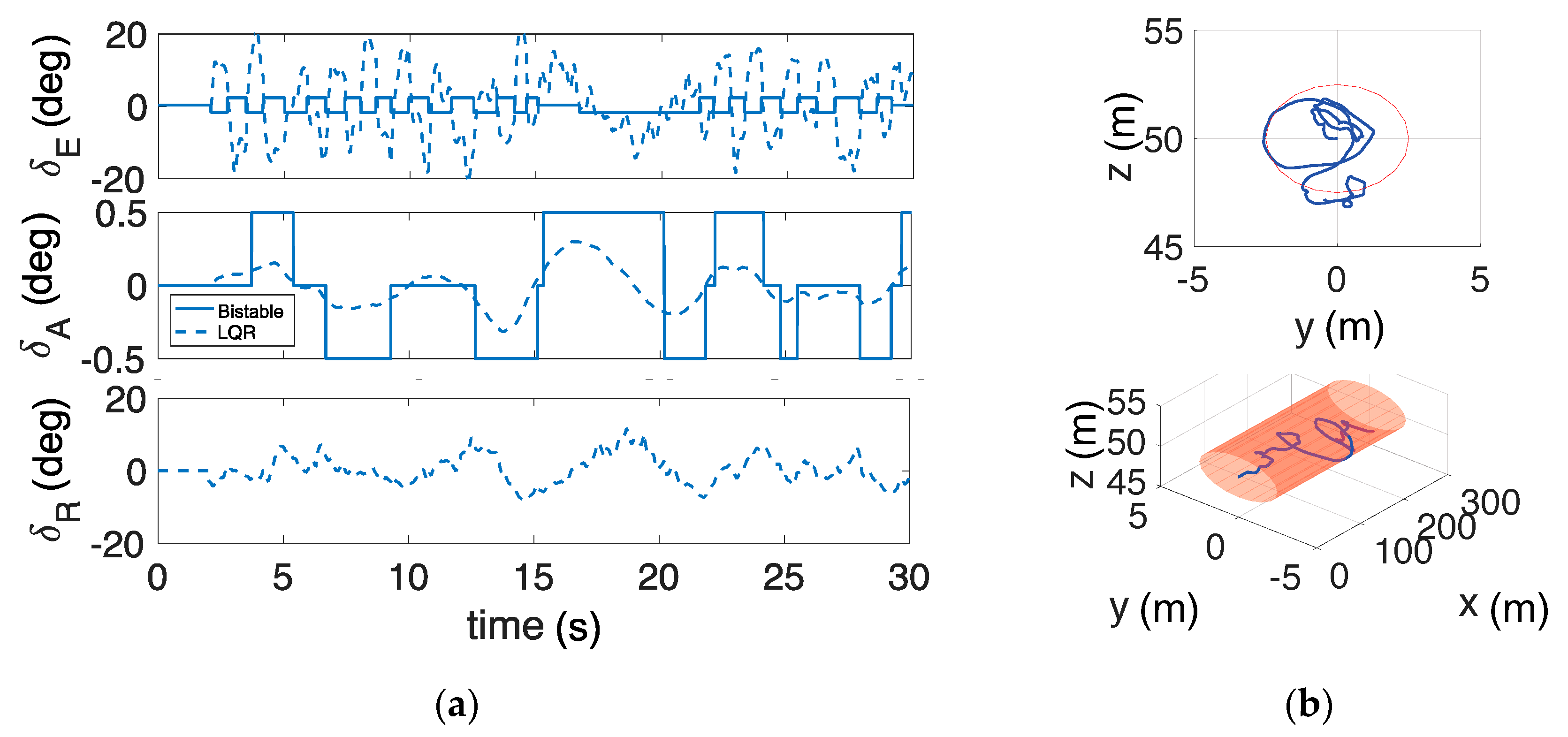
3.1.2. Closed-Loop Simulations
- (αDES − α) and (qDES − q), with αDES and qDES equal to αTRIM and to zero respectively, for longitudinal stability;
- (pDES − p) and (rDES − r), with pDES and rDES equal to zero for lateral–directional stability.
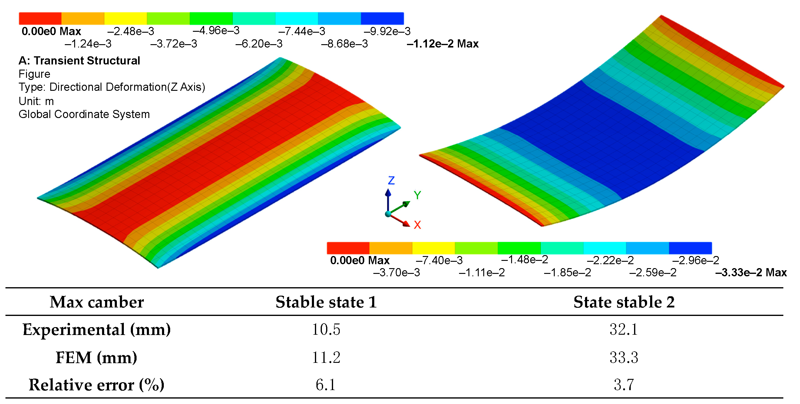
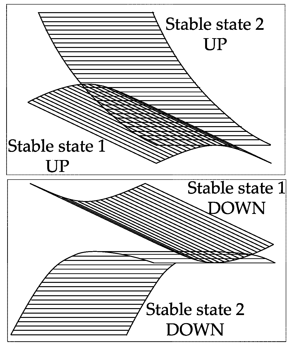
3.1.3. FEM vs. Experimental Plate Results
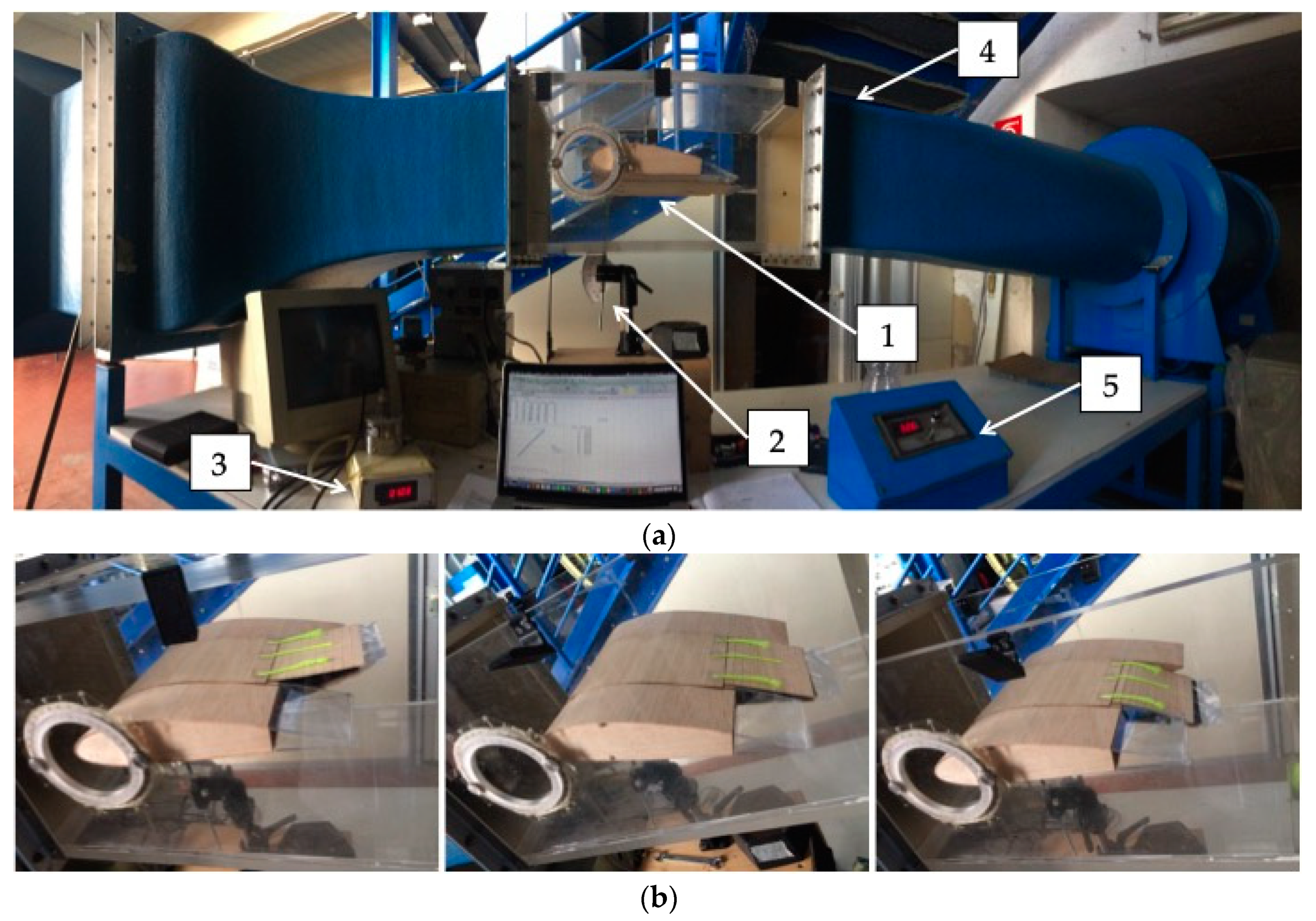
3.2. Wind Tunnel Experiment
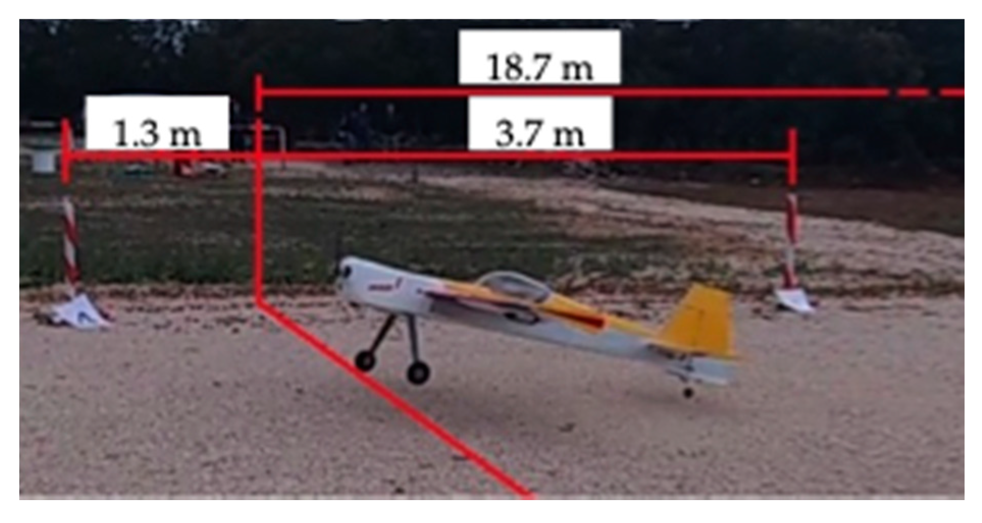
3.3. Takeoff Length: Numerical vs. Experimental Results
- Ground friction coefficient: in Simulink simulations this was constant, in actual tests the runway was definitely uneven and not properly described by a constant friction coefficient;
- Measurement time: the error of human reaction was about three tenths of a second;
- Wind: the actual weather was quickly changing, with small gusts from different directions, while no gust model was included in the Simulink code;
- UAV weight distribution: it was assumed homogeneous in the Simulink model for sake of simplicity, and at this stage of the research this small error can be accepted;
- Ground effect: it was not included in the Simulink model.
4. Conclusions
Author Contributions
Funding
Acknowledgments
Conflicts of Interest
References
- Dalamagkidis, K. Definitions and terminology. In Handbook of Unmanned Aerial Vehicles; Springer: Dordrecht, The Netherlands, 2015; pp. 43–55. ISBN 9789048197071. [Google Scholar]
- Valavanis, K.P. Introduction. In Advances in Unmanned Aerial Vehicles: State of the Art and the Road to Autonomy; Springer: Berlin/Heidelberg, Germany, 2007; Volume 33, ISBN 978-1-4020-6113-4. [Google Scholar]
- Zeng, Y.; Zhang, R.; Lim, T.J. Wireless communications with unmanned aerial vehicles: Opportunities and challenges. IEEE Commun. Mag. 2016, 54, 36–42. [Google Scholar] [CrossRef]
- Saad, W.; Mozaffari, M.; Yin, C.; Hong, C.S.; Chen, M.; Debbah, M. Caching in the Sky: Proactive Deployment of Cache-Enabled Unmanned Aerial Vehicles for Optimized Quality-of-Experience. IEEE J. Sel. Areas Commun. 2017, 35, 1046–1061. [Google Scholar]
- Hodgson, J.C.; Koh, L.P. Best practice for minimising unmanned aerial vehicle disturbance to wildlife in biological field research. Curr. Biol. 2016. [Google Scholar] [CrossRef] [PubMed]
- Anderson, K.; Gaston, K.J. Lightweight unmanned aerial vehicles will revolutionize spatial ecology. Front. Ecol. Environ. 2013, 11, 138–146. [Google Scholar] [CrossRef]
- Cano, E.; Horton, R.; Liljegren, C.; Bulanon, D. Comparison of Small Unmanned Aerial Vehicles Performance Using Image Processing. J. Imaging 2017. [Google Scholar] [CrossRef]
- Balek, J.; Blahůt, J. A critical evaluation of the use of an inexpensive camera mounted on a recreational unmanned aerial vehicle as a tool for landslide research. Landslides 2017. [Google Scholar] [CrossRef]
- Battipede, M.; Vazzola, M.; Tancredi, D. Innovative Piloting Technique for a Semi-Autonomous UAV Lighter-Than-Air Platform Simulator. In Proceedings of the AIAA Modeling and Simulation Technologies Conference; American Institute of Aeronautics and Astronautics: Reston, VI, USA, 2012. [Google Scholar]
- Hosseini, S.; Mesbahi, M. Energy-Aware Aerial Surveillance for a Long-Endurance Solar-Powered Unmanned Aerial Vehicles. J. Guid. Control Dyn. 2016, 39, 1980–1993. [Google Scholar] [CrossRef]
- Panagiotou, P.; Kaparos, P.; Salpingidou, C.; Yakinthos, K. Aerodynamic design of a MALE UAV. Aerosp. Sci. Technol. 2016, 50, 127–138. [Google Scholar] [CrossRef]
- Panagiotou, P.; Giannakis, E.; Savaidis, G.; Yakinthos, K. Aerodynamic and structural design for the development of a MALE UAV. Aircr. Eng. Aerosp. Technol. 2018, 90, 1077–1087. [Google Scholar] [CrossRef]
- Sharma, R.; Panigrahi, R.K. Stokes based sigma filter for despeckling of compact PolSAR data. IET Radar Sonar Navig. 2018, 12, 475–483. [Google Scholar] [CrossRef]
- Kontogiannis, S.G.; Ekaterinaris, J.A. Design, performance evaluation and optimization of a UAV. Aerosp. Sci. Technol. 2013, 29, 339–350. [Google Scholar] [CrossRef]
- Nicassio, F.; Scarselli, G.; Pinto, F.; Ciampa, F.; Iervolino, O.; Meo, M. Low energy actuation technique of bistable composites for aircraft morphing. Aerosp. Sci. Technol. 2018, 75, 35–46. [Google Scholar] [CrossRef]
- Scarselli, G.; Maffezzoli, A.; Nicassio, F. Mechanical characterization of bistable laminates for very small aircraft morphing applications. In Proceedings of the Health Monitoring of Structural and Biological Systems XII, Denver, CO, USA, 4–8 March 2018; p. 61. [Google Scholar]
- De Breuker, R.; Werter, N. On the Importance of Morphing Deformation Scheduling for Actuation Force and Energy. Aerospace 2016, 3, 41. [Google Scholar] [CrossRef]
- Arena, M.; Nagel, C.; Pecora, R.; Schorsch, O.; Concilio, A.; Dimino, I. Static and Dynamic Performance of a Morphing Trailing Edge Concept with High-Damping Elastomeric Skin. Aerospace 2019, 6, 22. [Google Scholar] [CrossRef]
- Sofla, A.Y.N.; Meguid, S.A.; Tan, K.T.; Yeo, W.K. Shape morphing of aircraft wing: Status and challenges. Mater. Des. 2010, 31, 1284–1292. [Google Scholar] [CrossRef]
- Pecora, R.; Barbarino, S.; Concilio, A.; Lecce, L.; Russo, S. Design and functional test of a morphing high-lift device for a regional aircraft. J. Intell. Mater. Syst. Struct. 2011, 22, 1005–1023. [Google Scholar] [CrossRef]
- Della Vecchia, P.; Corcione, S.; Pecora, R.; Nicolosi, F.; Dimino, I.; Concilio, A. Design and integration sensitivity of a morphing trailing edge on a reference airfoil: The effect on high-altitude long-endurance aircraft performance. J. Intell. Mater. Syst. Struct. 2017, 28, 2933–2946. [Google Scholar] [CrossRef]
- Nicassio, F.; Scarselli, G.; Avanzini, G.; Del Core, G. Numerical and experimental study of bistable plates for morphing structures. In Proceedings of the Active and Passive Smart Structures and Integrated Systems 2017, Portland, OR, USA, 25–29 March 2017; p. 101640K. [Google Scholar]
- Kim, S.W.; Lee, J.Y.; Cho, K.J. Towards a bistable morphing winglet for unmanned aerial vehicle (UAV). In Proceedings of the 2013 44th International Symposium on Robotics, Seoul, Korea, 24–26 October 2013; pp. 1–3. [Google Scholar]
- Mills, J.; Ajaj, R. Flight Dynamics and Control Using Folding Wingtips: An Experimental Study. Aerospace 2017, 4, 19. [Google Scholar] [CrossRef]
- Wang, B.; Fancey, K.S. A bistable morphing composite using viscoelastically generated prestress. Mater. Lett. 2015, 158, 108–110. [Google Scholar] [CrossRef]
- Tawfik, S.A.; Stefan Dancila, D.; Armanios, E. Unsymmetric composite laminates morphing via piezoelectric actuators. Compos. Part A Appl. Sci. Manuf. 2011, 42, 748–756. [Google Scholar] [CrossRef]
- Soken, H.E.; Ersin Soken, H.; Yenal Vural, S.; Hajiyev, C.; Vural, S.Y. Equations of Motion for an Unmanned Aerial Vehicle. In State Estimation and Control for Low-cost Unmanned Aerial Vehicles; Springer International Publishing: Cham, Switzerland, 2015; pp. 9–23. [Google Scholar]
- XFOIL Subsonic Airfoil Development System. Available online: http://web.mit.edu/drela/Public/web/xfoil (accessed on 6 March 2019).
- Scarselli, G.; Nicassio, F.; Pinto, F.; Ciampa, F.; Iervolino, O.; Meo, M. A novel bistable energy harvesting concept. Smart Mater. Struct. 2016. [Google Scholar] [CrossRef]
- ANSYS Product Launcher. Available online: https://ansyshelp.ansys.com (accessed on 6 March 2019).
- Hexcel Prepreg. Available online: https://www.hexcel.com/Resources/DataSheets/Prepreg (accessed on 6 March 2019).
- MACRO FIBER COMPOSITE–Smart-Material. Available online: https://www.smart-material.com/Datasheets-MFC.html (accessed on 6 March 2019).
- Avanzini, G.; Nicassio, F.; Scarselli, G. Reduced-Order Short-Period Model of Flexible Aircraft. J. Guid. Control Dyn. 2017, 40, 2017–2029. [Google Scholar] [CrossRef]


| Specification | Symbol | Value | Specification | Value |
|---|---|---|---|---|
| Mass and Inertia | Aerodynamics | |||
| Mass | M | 6.5 kg | Wing and Tail Profile | NACA 0011 |
| UAV moment of inertia | Ix | 0.681 kg m2 | Thrust | |
| Iy | 1.375 kg m2 | DLE Engine Power | 5 CV | |
| Iz | 2.0121 kg m2 | DLE Engine Displacement | 30 cc | |
| Ixy | −0.001 kg m2 | Propeller Diameter | 0.48 m | |
| Ixz | 0.022 kg m2 | Propeller Pitch | 0.30 m | |
| Iyz | 0.0001 kg m2 | - | - | |
| Technical Data | Value |
|---|---|
| Nominal cured ply thickness | 0.131 mm |
| Nominal laminate density | 1570 kg m−3 |
| Young’s modulus 0° direction | 165 GPa |
| Young’s modulus 90° direction | 11.4 GPa |
| Coefficient of thermal expansion 0° direction | 6 × 10⁻⁷ C−1 |
| Coefficient of thermal expansion 90° direction | 2.86 × 10⁻⁵ C−1 |
| S (mm) | Deflection f (mm) | Deflection Angle δ (°) |
|---|---|---|
| 40 | 84.1 | ≈28 |
| 80 | 56.9 | ≈20 |
| 120 | 27.1 | ≈10 |
| AOA (°) | Initial Stable State | |||
|---|---|---|---|---|
| 1—UP | 2—UP | 1—DOWN | 2—DOWN | |
| Snap Speed (km/h) | ||||
| +20 | 85 | - | - | 35 |
| +15 | - | - | - | 45 |
| +10 | - | - | - | 50 |
| +5 | - | - | - | 65 |
| 0 | - | 60 | - | 70 |
| −5 | - | 70 | - | - |
| −10 | - | 55 | - | - |
| −15 | - | 45 | - | - |
| Test | Results | Experimental | Simulink | Error (%) | |
|---|---|---|---|---|---|
| 1 | δE = −10° | Runway (m) | 18.7 | 17.6 | 5.9 |
| Time (s) | 4 | 3.8 | 5.0 | ||
| 2 | δE = 0° | Runway (m) | 35 | 35 | - |
| Time (s) | 6 | 5.7 | 5.0 | ||
| 3 | 0–3 s, δE = 0° | Runway (m) | 12.5 | 13.6 | −8.8 |
| from 3 s on, δE = −10° | Time (s) | 3.5 | 3.2 | 5.7 | |
© 2019 by the authors. Licensee MDPI, Basel, Switzerland. This article is an open access article distributed under the terms and conditions of the Creative Commons Attribution (CC BY) license (http://creativecommons.org/licenses/by/4.0/).
Share and Cite
Nicassio, F.; Scarselli, G. Simulation and Test of Discrete Mobile Surfaces for a RC-Aircraft. Aerospace 2019, 6, 122. https://doi.org/10.3390/aerospace6110122
Nicassio F, Scarselli G. Simulation and Test of Discrete Mobile Surfaces for a RC-Aircraft. Aerospace. 2019; 6(11):122. https://doi.org/10.3390/aerospace6110122
Chicago/Turabian StyleNicassio, Francesco, and Gennaro Scarselli. 2019. "Simulation and Test of Discrete Mobile Surfaces for a RC-Aircraft" Aerospace 6, no. 11: 122. https://doi.org/10.3390/aerospace6110122
APA StyleNicassio, F., & Scarselli, G. (2019). Simulation and Test of Discrete Mobile Surfaces for a RC-Aircraft. Aerospace, 6(11), 122. https://doi.org/10.3390/aerospace6110122