Abstract
Modern transport aircraft wings have reached near-peak levels of energy-efficiency and there is still margin for further relevant improvements. A promising strategy for improving aircraft efficiency is to change the shape of the aircraft wing in flight in order to maximize its aerodynamic performance under all operative conditions. In the present work, this has been developed in the framework of the Clean Sky 2 (REG-IADP) European research project, where the authors focused on the design of a multifunctional twistable trailing-edge for a Natural Laminar Flow (NLF) wing. A multifunctional wing trailing-edge is used to improve aircraft performance during climb and off-design cruise conditions in response to variations in speed, altitude and other flight parameters. The investigation domain of the novel full-scale device covers 5.15 m along the wing span and the 10% of the local wing chord. Concerning the wing trailing-edge, the preliminary structural and kinematic design process of the actuation system is completely addressed: three rotary brushless motors (placed in root, central and tip sections) are required to activate the inner mechanisms enabling different trailing-edge morphing modes. The structural layout of the thin-walled closed-section composite trailing-edge represents a promising concept, meeting both the conflicting requirements of load-carrying capability and shape adaptivity. Actuation system performances and aeroelastic deformations, considering both operative aerodynamic and limit load conditions, prove the potential of the proposed structural concept to be energy efficient and lightweight for real aircraft implementation. Finally, the performance assessment of the outer natural laminar flow (NLF) wing retrofitted with the multifunctional trailing-edge is performed by high-fidelity aerodynamic analyses. For such an NLF wing, this device can improve airplane aerodynamic efficiency during high speed climb conditions.
1. Introduction
Worldwide air passenger traffic is predicted to grow at an average 4–5% per annum over the next few decades [1]. As the number of flights increases, environmental requirements, such as emissions and noise, will impose significant challenges for next generation transport aircraft development.
According to Europe’s vision for aviation [1], technological breakthroughs are necessary to accomplish a major step towards the environmental goals of a 75% reduction in CO2 emissions per passenger/kilometre, a 90% cut in NOx emissions, a 65% reduction of perceived aircraft noise levels (all percentages referred to the transport aircraft performances measured in 2000).
Nowadays, modern transport aircraft wings have reached near-peak levels of energy-efficiency and further improvements seem extremely difficult to obtain. Indeed, aircraft wings are still designed with a fixed geometry fully optimized in only a few design points, which may not be so optimal for the entire flight mission. Therefore, whereas an aircraft operates in off-design conditions, sub-optimal performances lead to an increase of fuel burnt with impacts on air-pollution and aircraft operative costs. Morphing the shape of the aircraft wing during flight represents a very promising strategy to achieve some benefits throughout the entire aircraft mission [2].
During the very early days of aviation history, the possibility of changing the wing shape was considered a crucial design factor in order to generate lift and maintain lateral equilibrium. In 1903, the Wright Brothers achieved the first sustained, powered, heavier-than-air flight in a machine of their own design and construction [3]. After some experiments with kites and gliders, they developed a revolutionary wing design, enabling the lateral equilibrium of the aircraft: lateral control was indeed realized by twisting the rear of their fabric-and-wood wings in opposite directions [4]. Soon after, as aircraft became heavier and faster, engineers were forced to switch to stiff wings retrofitted with flaps and ailerons to satisfy the need for higher wing loading; morphing of these surfaces was proven to be impractical because of the higher structural stiffness required to withstand higher aerodynamic loads due to increased performances.
Over the years, researchers and designers have conceived several promising concepts to enable shape-changing morphing devices. All wing morphing concepts can be categorized into three major types [5]: global plan form alteration (involving global aircraft characteristics such as span, chord and sweep changes), out-of-plane transformation (twist, dihedral, span-wise bending) and airfoil adjustment (camber and thickness). In each case, the design of smooth control-surface geometry variation must strike a balance between proper structural stiffness to withstand the external aerodynamic loads without appreciable deformations (or arising of aeroelastic instability issues) and sufficient flexibility to make the shape change possible with a reasonable amount of actuation power.
In the mid 1980s, the Mission Adaptive Wing (MAW) research program demonstrated the concept of changing the wing in flight. The U.S. Air Force Research Laboratory and Boeing designed and tested adaptive wings that were installed on an F-111 aircraft [6]. Flight tests conducted on AFTI/F-111 aircraft confirmed the expected performance improvement: 20% range enhancement, 20% aerodynamic efficiency growth, 15% increase of wing air load at constant bending moment [6].
At the end of 1990s, the DaimlerChrysler Aerospace Airbus and DLR launched the research project ADIF (Adaptive Wing) and in this framework they proposed a concept to camber and twist the wing trailing edge [7]. The structural layout was conceived to be used for the replacement and enhancement of the flap trailing edge of the A340-300. Investigations of span-wise differential camber variation confirmed 12–15% reduction of the root bending moments (RBM) through the redistribution of the span-wise aerodynamic load.
Within SARISTU—an industrial oriented research project in the frame of the 7th European framework Program (2011–2015)—different new concepts of morphing devices were developed and experimented in large wind tunnel tests (WT) at TsAGI facilities [8].
Different studies showed how controlled wing twisting can be an effective alternative for ailerons and that the amount of wing twist (washout) during the flight envelope can reduce he induced drag thus resulting in higher efficiency and less amount of fuel burn [9,10]. For this reason, different concepts were employed to induce wing twisting. Several works have been done on structural concepts for aerodynamic surfaces with adjustable torsional stiffness by means of rigid-body mechanisms. Indeed, the stiffness control for some selected components of the lifting surfaces was demonstrated to be a promising idea for the implementation of smart roll control [11] and adaptive lift-to-drag vertical tail ratio [12]. In such a case, the structural concept can change its own stiffness thanks to rotary wing spars with a controllably rigid attachment that permits aeroelastic amplification [12]. The Adaptive Torsion Wing (ATW) concept was based on the idea of a two-spar thin-walled closed section wing-box with all-movable spar webs in chordwise direction [13].
These first concepts for inducing twist in a conventional wing structure were developed to reduce the torsion stiffness of the structure and, usually, high forces or moments were anyway required to enable the predicted twisted shape [14]. In order to overcome the high-energy demand to control wing torsion and therefore to avoid the adoption of heavy actuators, a concept relying on warping-induced deformations to an open-section airfoil was designed and tested [15]. Within the EU FP7 CHANGE project, a similar concept was investigated for a 25 kg UAV [16]. A very interesting way to implement wing-twist morphing was finally addressed in Reference [17]. Here, the wing-twist was controlled by working on the bending-twist coupling induced by changes of shear centre location; the prototype, conceived for a glider of the FAI 15 m class, used smart material with controllable shear stiffness to adaptively modify the shear centre positions of wing cross sections.
Most of the structural concepts conceived for wing twist are related to the trailing edge area where high benefits could be proved to be exploited on subsonic transport aircraft. Optimization of wing trailing-edge shape could assure significant drag reduction within the flight envelope. With respect to a civil transport aircraft configuration using conventional trailing-edge control surfaces, the benefits that might be brought by a morphing-camber system to the aircraft efficiency can approach more than 10 per cent, in off-design flight conditions and 1–3 per cent in cruise [18]. Estimated benefits for a reference transport aircraft (L-1011) prove the positive effects of variable camber system based on aileron-type trailing-edge surface deflections.
A competitive concept to enhance aircraft performances could be represented by a multifunctional trailing edge, retrofitting a Fowler flap, implementing wing camber-morphing through rigid surface deflections (for lift-to-drag ratio improvement [18]) and continuous span-wise twist control for root bending moments (RBM) alleviation (through the redistribution of the span-wise aerodynamic load [19]).
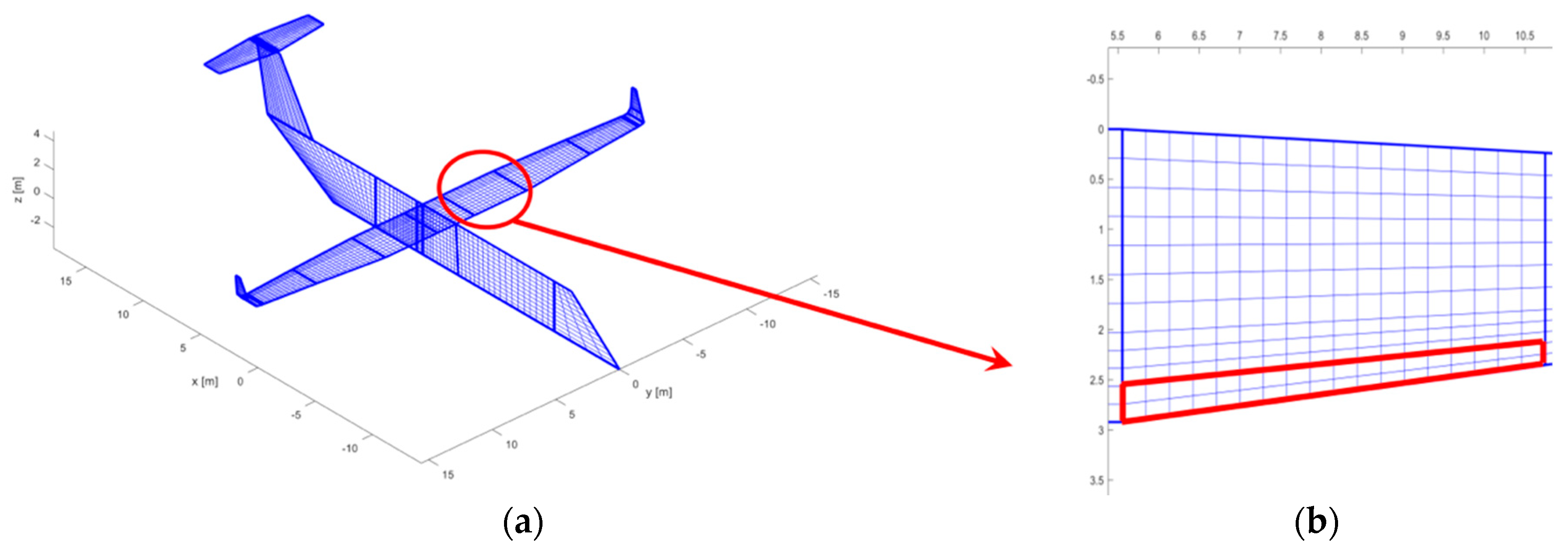
Reporting about the research activities developed in the framework of the Airgreen2 project (running within the “Clean Sky 2” Regional Integrated Development Platform), this paper is focused on the preliminary design of a full-scale composite multifunctional and twistable trailing-edge retrofitting the outboard morphing Fowler flap of a turboprop regional aircraft. The investigation domain of the novel device (Figure 1) covers 5.15 m in wing span direction and the 10% of the wing local chord. The two functionalities of the flap tab (/trailing edge) device are activated when the fowler flap is stowed in the wing during cruise, climb and off-design flight conditions:
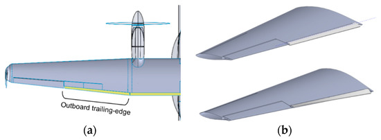
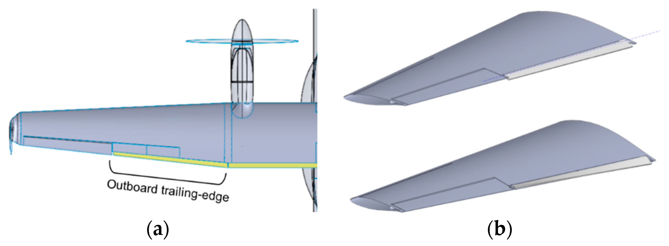
Figure 1.
Multifunctional Twistable Wing TE: (a) Outboard wing TE, (/flap tab) investigation region for the structural concept; (b) Explanation of the outboard wing TE functionalities, (upper) rigid deflection of the Fowler flap tip segment, (lower) continuous span-wise twist along the outboard wing span.
- Mode A: Rigid deflections of the Fowler flap tip segment (from the 90% to 100% of the local wing chord) within the angles range [+10°/−10°] (downwards/upwards),
- Mode B: “Continuous” span-wise twist with a maximum differential twist-angle of 10° between the tip and root sections of the flap (up to ±5° at the root and tip sections respectively).
Continuous span-wise twist is achieved by elastic torsional deformation of the flap tab via distributed actuators. The conceived structural concept deals with issues related to real implementation on large aircraft and is based on a reasonable number of subcomponents integrating lightweight and energy efficient actuation systems.
2. Aerodynamic Design of the Multifunctional Twistable Trailing-Edge
The study presented in this section had the objective to define the optimal morphed shapes to be implemented for the wing trailing-edge (/flap tab) in order to improve the aircraft performance in high speed (climb) conditions.
Retrofitting the segment of the AG2-NLF wing flap system (designed in cruise condition) with a multifunctional trailing-edge (/tab), the span load distribution could be optimized aiming at improve the global aircraft aerodynamic performance.
The 3D computations of the aerodynamic flow around the airplane configurations have been carried out, referring to the ONERA elsA code [20]. This high fidelity CFD software solves the RANS equations on structured multi-block grids by a cell-centred finite volume technique. Spatial discretization uses the second order centred scheme of Jameson with 2nd and 4th order artificial dissipation. Convergence to steady flow solution is carried out thanks to a backward Euler technique with robust LU-SSOR implicit scheme method. The convergence is accelerated by the use of multigrid techniques for steady flows. Different turbulence models are available in elsA and in this work the Spalart-Allmaras turbulence model was used with the QCR modification [21]. In the RANS computations, the ONERA elsA software has the capability to compute laminar flow regions and to determine the transition location, by using the so-called AHD compressible criterion for Tollmien-Schlichting instabilities [22] and the so-called C1 criterion for crossflow instabilities [23], within the iterative convergence process.
The generation of the wing shapes with morphed elements is done through the use of a grid deformation technique that has been used also in SARISTU project ([24]). The surface grid is firstly deformed according to the requested shape. Then, a displacement field of the grid nodes is derived for a volumetric transfinite deformation technic applied to the initial grid. The advantage of this method is that the same scripts can be used for the different computations, as the topological information is kept. The drawback is that it is based on the initial topology and some local grid inversion can be found if deformation is too large.
Trailing-Edge Aerodynamic Performance
For the AG2-NLF regional airplane, multifunctional twistable trailing-edge could help to recover the laminar extent by an adaptation of pressure gradient in off-design condition. Considering the related to high speed climb condition, free transition computations show that laminar flow on the upper surface starts to be lost.
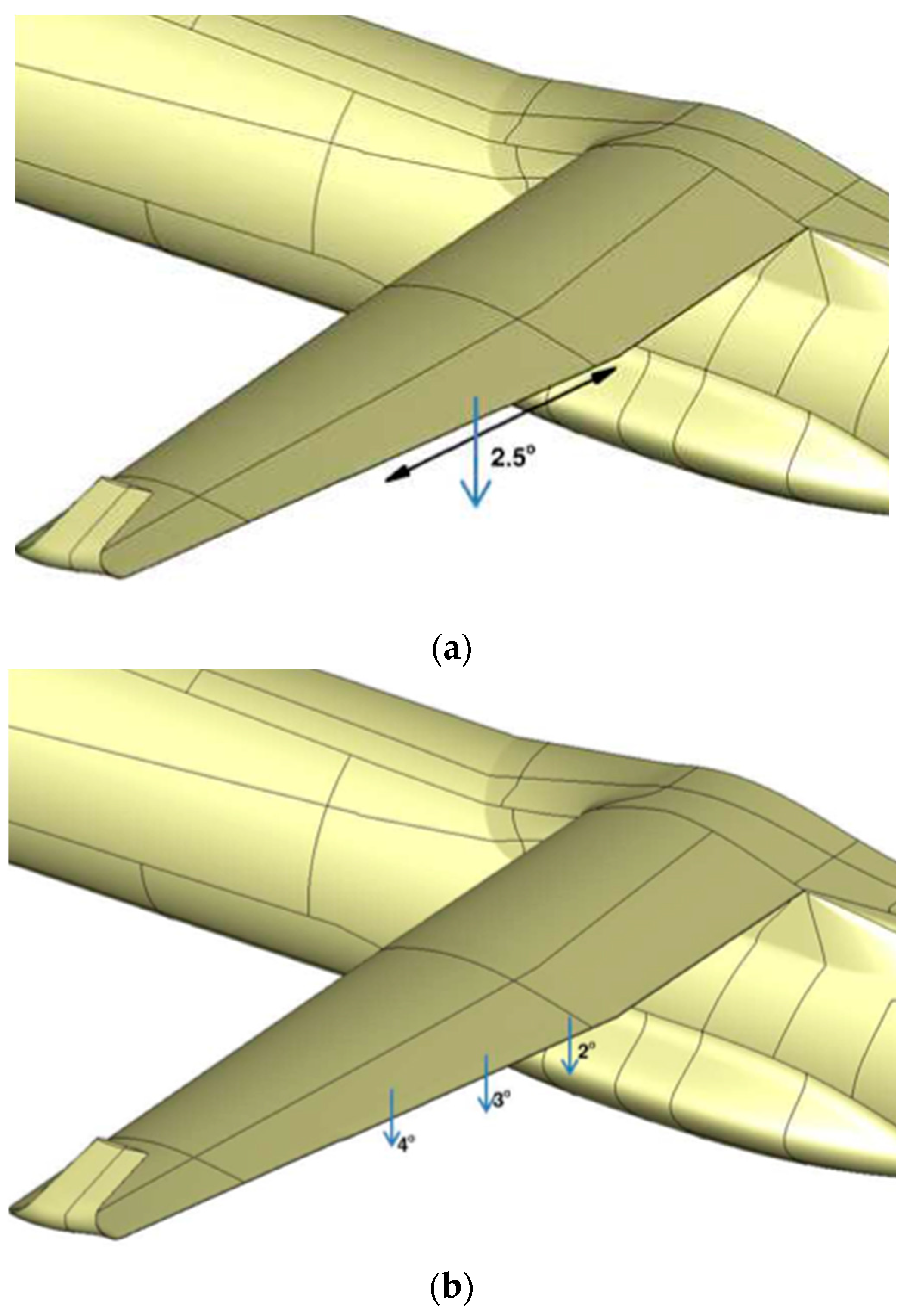
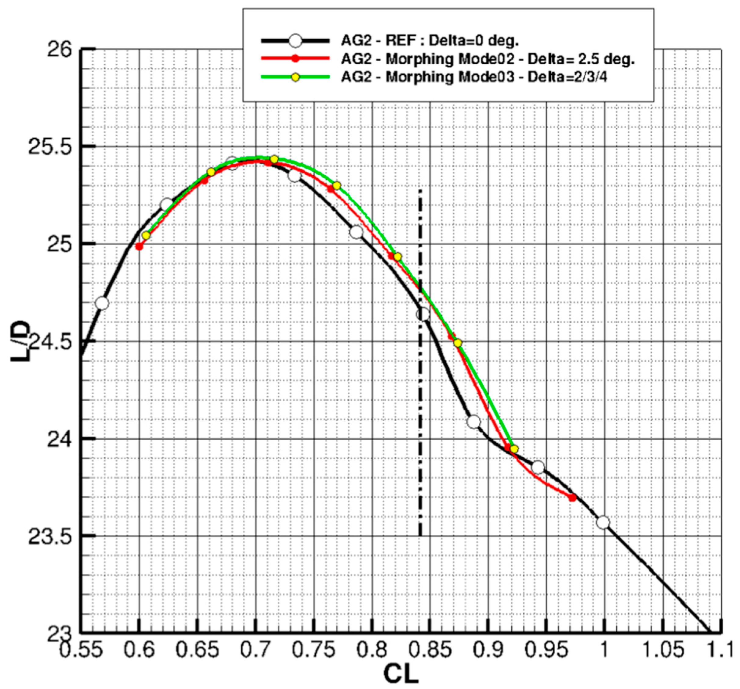
Figure 2 presents the different configurations considered for the multifunctional twistable trailing-edge: a rigid trailing-edge deflection (mode A) equal to 2.5° is presented in Figure 2a, while a discretely increasing distribution of deflection angles along the span (mode B, angles 4°/3°/2°) is sketched in Figure 2b. Figure 3 compares the computed Lift over Drag ratio (L/D) evolution versus in climb conditions for both the mentioned configurations. The L/D for the baseline configuration (no morphing) is also reported in Figure 3. As expected, the efficiency of the trailing-edge morphing concept for the AG2-NLF airplane is visible for high , where an increase of about 0.4 in Lift over Drag ratio is found. More in detail, according to Figure 3, the increase of Lift-over-Drag ratio (L/D) is up to +2% considering the evolution at climb condition ( at ). This value resulted fully compliant with the industrial expectations in terms of benefits brought by the new technology; although marginal at aircraft level, the 2% increase of L/D was indeed considered very relevant at fleet level in force of the very positive impacts on large scale operations.
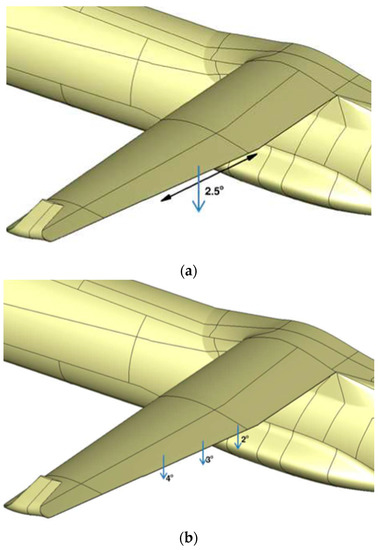
Figure 2.
Configurations for the multifunctional TE: (a) Trailing-edge rigid rotation (Mode A) equal to 2.5°; (b) Continuous increase in deflection angles (Mode B) from tip to root (4°/3°/2°).
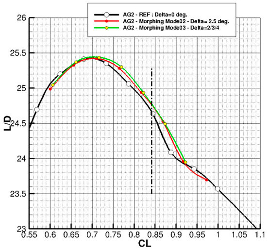
Figure 3.
Performance of the multifunctional trailing-edge.
3. Concept Description
The concept of multifunctional twistable wing trailing-edge investigated in the present work is based on the idea of retrofitting the tab of an outer board Fowler flap to enable new functionalities during cruise and climb flight conditions. The investigation domain is presented in Figure 1 and the summary of main geometric data in Table 1.

Table 1.
Flap tab geometric data and Limit Load Condition considered for its design (loads obtained by means of DLM).
During off-design cruise flight conditions, the TE can rigidly rotate around its main hinge axis, during the climb phase, continuous span-wise twist can be enabled as explained in Figure 1; in both cases the goal is always to enhance the aerodynamic efficiency of the wing and get consequent fuel savings. The multifunctional twistable trailing-edge concept is a thin-walled closed section whose functionalities are enabled thanks to the actuation torque provided by three brushless rotary motor, properly amplified by harmonic drive gear units and inner mechanisms. As rotary actuators are activated, the inner mechanisms can transfer torque to the structural concept thus providing the required performance. Upon the actuation of the active ribs, the Fowler flap tab is put in movement thus changing the external shape of the trailing edge (Figure 1 and Figure 4); if the shape change of each rib is prevented by locking the actuation system, the composite flap tab is elastically stable under the action of external aerodynamic loads. The rigid rotation of the wing TE (Figure 1b, upper) can be obtained synchronizing the three actuators (R1, R2, R3). Conversely, “continuous” span-wise elastic twist of the flap trailing-edge (Figure 1b, lower) can be activated by providing differential actuation control. For example, linear span-wise tab twist can be enabled providing a clockwise rotation to the tip actuator (R3) and an anti-clockwise rotation to the root actuator (R1) while locking the central actuator (R2). Fast and reliable analytical and numerical methods in combination with rational design criteria, were implemented to assess the structural layout and actuation system with reference to the most severe load condition expected in service (limit load condition); AL2024-T5 alloy was used for the great part of the items of the inner mechanism, while 17-4PH steel was used for the fork link of the leverage mechanism. A glass fibre prepreg with HexPly913 from Hexcel composites was used for the skin, “active” ribs and C-shape spars of the trailing edge.
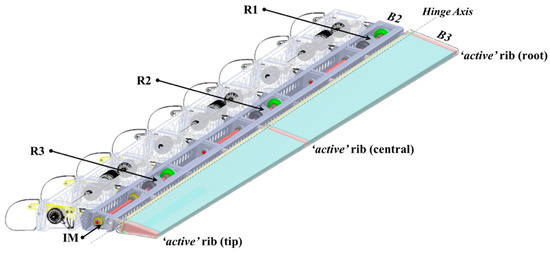
Figure 4.
Multifunctional Twistable Wing Trailing-edge mounted on the tip of a Fowler flap: 3D-CAD.
The final structural layout (Figure 4) was analysed by means of an advanced finite element model which finally proved:
- the capability of the actuation system to enable morphing through smooth rigid-body kinematic of the inner mechanisms;
- the absence of any local plasticization and elastic instability at limit load condition for the items made of aluminium and steel alloy;
- the strains for items made of GFRP to be lower than the maximum allowed strains at the limit load (both along the fibre direction and transversally with respect to the fibres);
- the absence of any failure up to the ultimate load condition (i.e., limit loads multiplied by a contingency factor equal to 1.5).
Aerodynamic Design Load Condition
According to reference regulations ([25]), the structural design of any movable control surface on a large airplane must comply with the following requirements:
- capability to support limit loads without permanent detrimental deformation and deformation levels not compromising safe operations (EASA CS 25.305(a));
- capability to withstand ultimate loads without failures in structural components or actuator systems;
- clearance from aeroelastic instability phenomena (EASA CS 25.629).
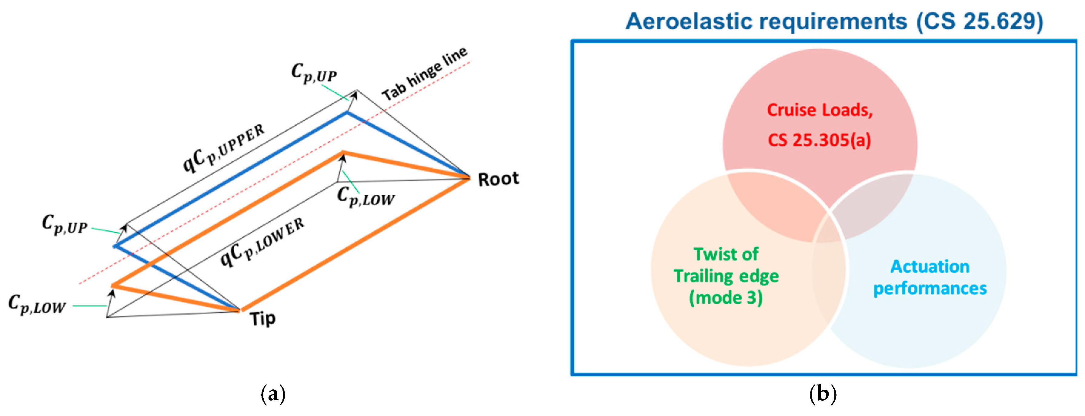
Moreover, when flying at dive speed, the control surface must be able to be deflected by an angle equal to one third of the maximum design deflection. This condition has been considered as limit operative configuration for the preliminary design of the device, being, the highest dynamic pressure occurring at the dive speed. The limit loads were evaluated by means of an in-house code implementing a 3D Doublet Lattice Method (DLM); the adopted aerodynamic model is depicted in Figure 5, limit resultant loads along the outer wing trailing edge (/flap tab) have been summarized in Table 1. In the preliminary design phase, the pressure distribution was considered as uniform on flap tab upper and lower external surfaces (Figure 6a). Particular attention was paid to the power required to morph the structure and to the consequent actuators size and weight; in summary, the entire preliminary design process of the system was driven by the need of simultaneously meeting different requirements (Figure 6b) in order to come to a solution of industrial relevance.
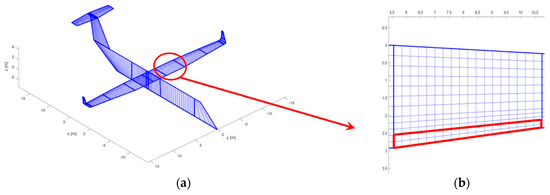
Figure 5.
Aerodynamic model used for limit load evaluation by means of DLM: (a) Aerodynamic Lattice of the reference regional aircraft TP90; (b) aerodynamic lattice of the outboard wing trailing-edge.
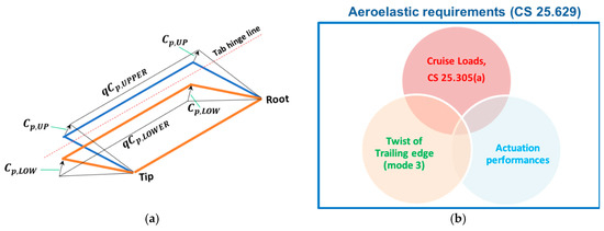
Figure 6.
Design condition: (a) Pressure distribution on TE upper and lower surfaces for limit load condition; (b) Requirements simultaneously fulfilled to integrate a multifunctional TE at aircraft level.
4. Actuation System: Design Process and Estimated Performances
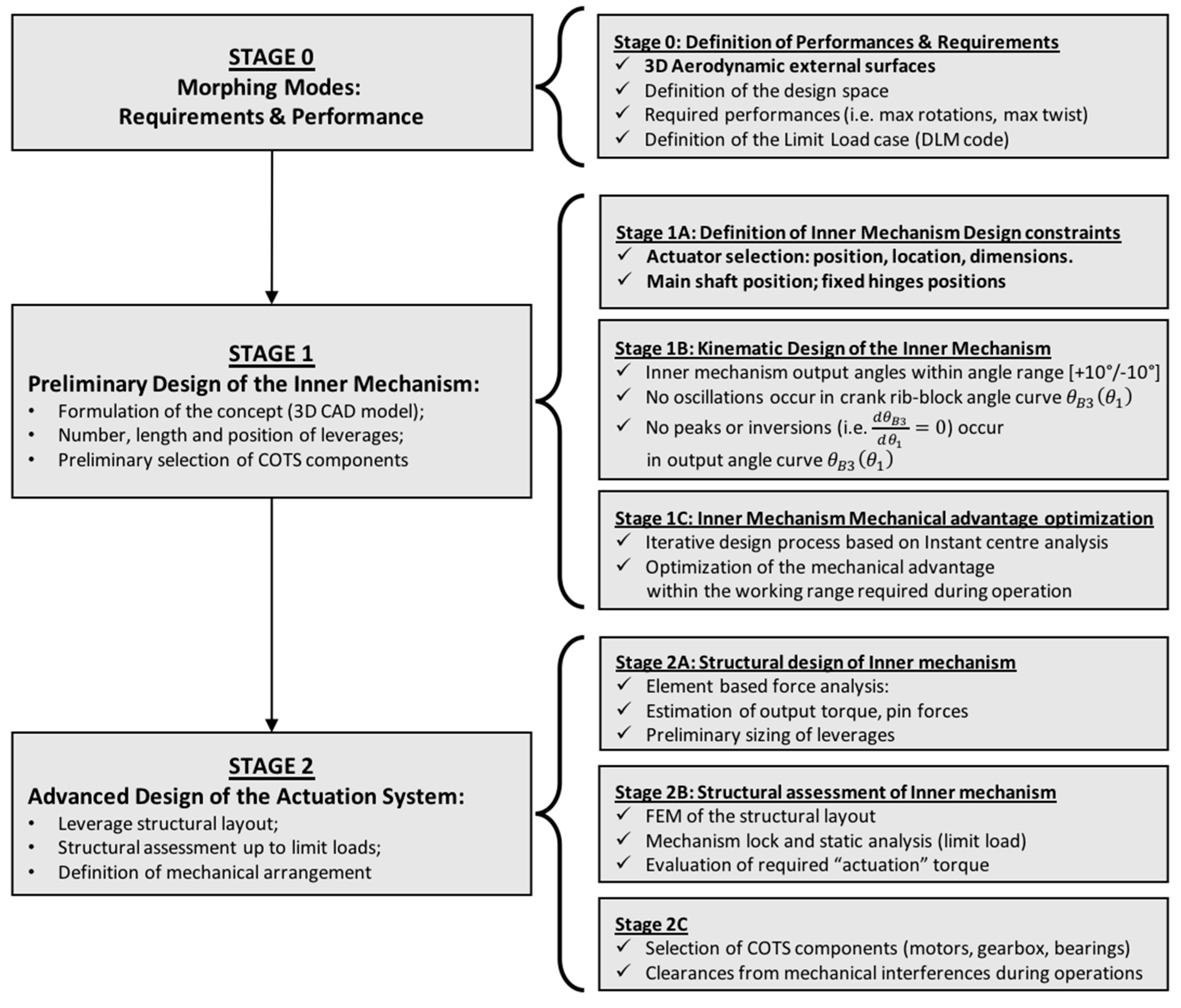
The core element of an adaptive structure is the actuation system including its transmission line. Interactions between the basic elements of this mechanized system and the external loads provide fundamental insight into the behaviour of the overall adaptive system. Power and weight reductions are of paramount importance to successfully integrate adaptive systems in large airplanes for improving performances and enlarge mission profiles. In Figure 7, the flow-chart of the actuation system design process is summarized.
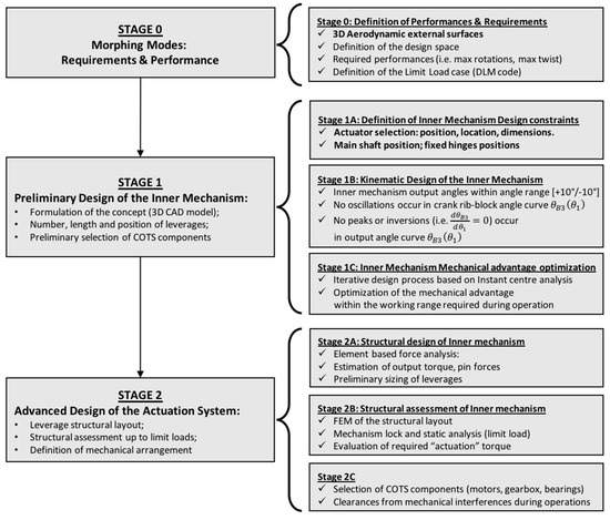
Figure 7.
Flow-chart of the actuation system design process.
4.1. Kinematic Design of the Inner Mechanism
The design engineer must ensure that the proposed mechanism will not fail under operating conditions. At the beginning of the design process, a tentative linkage has to be synthesized with the principal goal to provide the kinematic performances required by morphing operations; in a second stage, the obtained mechanism is properly investigated from the structural standpoint. The position of all the links or elements in the mechanism has to be evaluated for each increment of input motion and compared with the expected kinematic performance enabling the transition of the airfoil from its baseline configuration to the target morphed one.
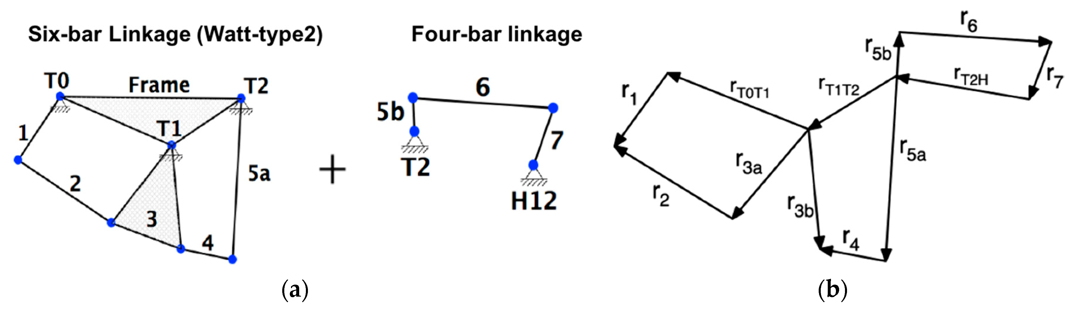
The tentative linkage was selected as the one that can be seen in Figure 8a: a Watt’s Six-bar plus a Four-bar linkage. In such a way, the hollow-shaft rotary brushless motor can transfer rotation from the crank element (link 1 in Figure 8a) to the output element (link 7 in Figure 8a).
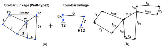
Figure 8.
Kinematic model of the inner mechanism: (a) full leverage can be seen as six-bar linkage plus a four-bar linkage; (b) Vector loop equations.
As a first step, the lengths and positions of the links were defined as function of the input angle as the full linkage is a single degree of freedom (DOF) mechanism. Indeed, assuming trial link lengths, unknown link angles were evaluated and each link, represented as a position vector, was completely defined for each increment of input motion. The approach to linkage position analysis generates a vector loop (or several loops) around the linkage as first proposed by Raven [26].
In Figure 8b, the links are represented as position vectors that form a vector loop. The lengths of the vectors are the link lengths, which are known. The choices of vector directions and sense, as indicated by their arrowheads, lead to this vector loop equation:
where position vectors are defined with complex number notation (with ).
Each vector loop can be expressed as Freudenstein’s equation; if we solve for the angle , output of first vector loop equation, we have:
Then, the first vector loop, expressed as Freudenstein’s Equation (2), can be simplified as:
where link lengths and known input angle terms have been collected as constants A, B and C:
The full inner mechanism is made up of three four-bar linkages in series, as shown in Figure 8b.
These vector loop Equation (1) can be solved in succession with the results of the first loop applied as input to the second loop. Note that there is a constant angular relationship between vectors and within ternary link 3. The solution for the four-bar linkage (4) is simply applied twice in the Watt’s Six-bar case:
and one more time for the last four-bar linkage in Figure 6a:
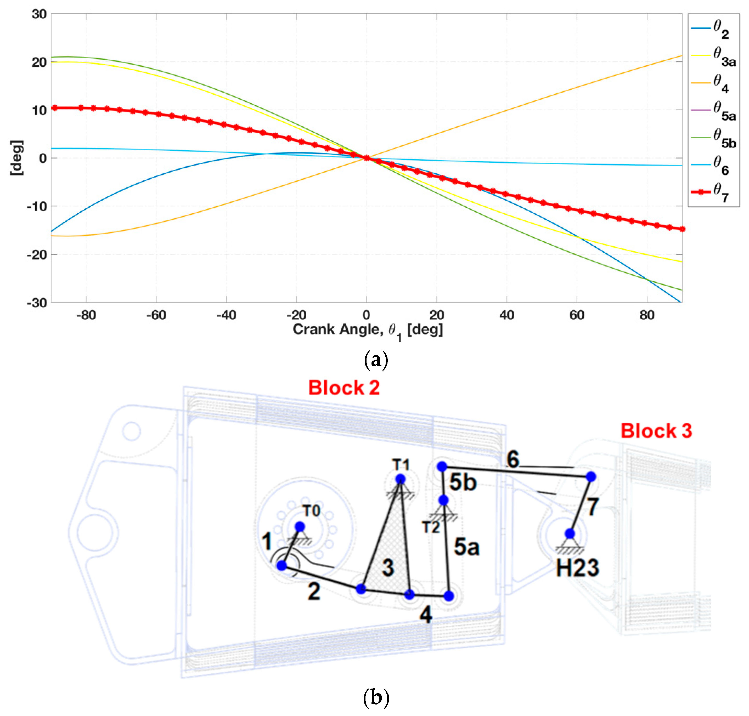
The independent variable is which will be controlled with the brushless motor. In such a way, each angle link was expressed as function of the crank angle (Figure 9a), once the link lengths were defined within the minimum available design space of the tip trailing-edge section (Figure 9b). When the hollow-shaft brushless rotary motor is activated, the input rotation is transferred to the crank element (link 1). Leverage’s output element (link 7) must provide adequate control action during trailing-edge evolution from baseline position to the target shape. As shown in Figure 9a, the final output angle curve was able to fulfill performance angle requirements within the range [+10°/−10°] with the following additional criteria observed to assure effective trailing-edge transition during morphing operations:

Figure 9.
Kinematic design of the inner mechanism: (a) Link Angles as function of the crank angle input rotation ; (b) Link lengths within the minimum available design space of the tip TE section.
When condition (8) is verified, inversion points (i.e., toggle positions of the linkage) are avoided and smoothness transition from the baseline position to the target shape (and vice versa) can occur.
4.2. Inner Mechanism Mechanical Advantage
Modern adaptive systems, designed for large demonstrators, are commonly based on the seamless integration of actuators, mechanisms and structures with the purpose of reshaping the external surface on demand. The reduction of power required to morph the structure and of the actuation system weight are of paramount importance to successfully integrate adaptive systems in large airplanes.
For this reason, an energy-efficient approach must be adopted since the preliminary design phase of the actuation system. Parameters capable to express interactions between the basic elements of this mechanized system and the external loads have to be defined to provide insight into the behaviour of the overall adaptive architecture. The mechanical advantage of a mechanism could be defined as the ratio between the output and the input torque [27]. In order to cut down the capacities of electro- mechanical actuators, the mechanical advantage of the inner mechanism within the TE angle working range should be as high as possible. For the inner mechanism (IM) in Figure 9b, the main output is the moment transferred around the trailing-edge hinge axis () and the input refers to the torque applied to the crank ().
Assuming that the friction and inertia are neglectable, according to the principle of the virtual works, the following relationship can be found for the inner mechanism:
where is the crank angular speed and is the angular speed around the trailing-edge hinge axis. According to the definition of instant center of rotation, at a given instant of time, a linkage mechanism undergoing planar movement has a point showing the same speed for both the input and output parts, thus the following relationship can be defined:
where is the instant centre between frame and input part (crank), is the instant centre between frame and output part, is the instant centre between input part and output part; is the distance of instant centers and , is the distance of instant centres and .
Let’s now recall the Aronhold-Kennedy’s theorem which deals with the three instant centres between three links of a system of rigid members [28]:
Aronhold-Kennedy’s Theorem:
The three instantaneous centres of three bodies moving relative to one another must lie along a straight line.
By returning to the inner mechanism obtained at the end of the kinematic design process (Figure 9b) and applying this theorem, we can further simplify Equation (10) as follows:
where is a first order instant centre and is a second order instant center.
Therefore, the mechanical advantage of the inner mechanism can be defined as a function of particular first order and second order Instant Centres (ICs) of the linkage:
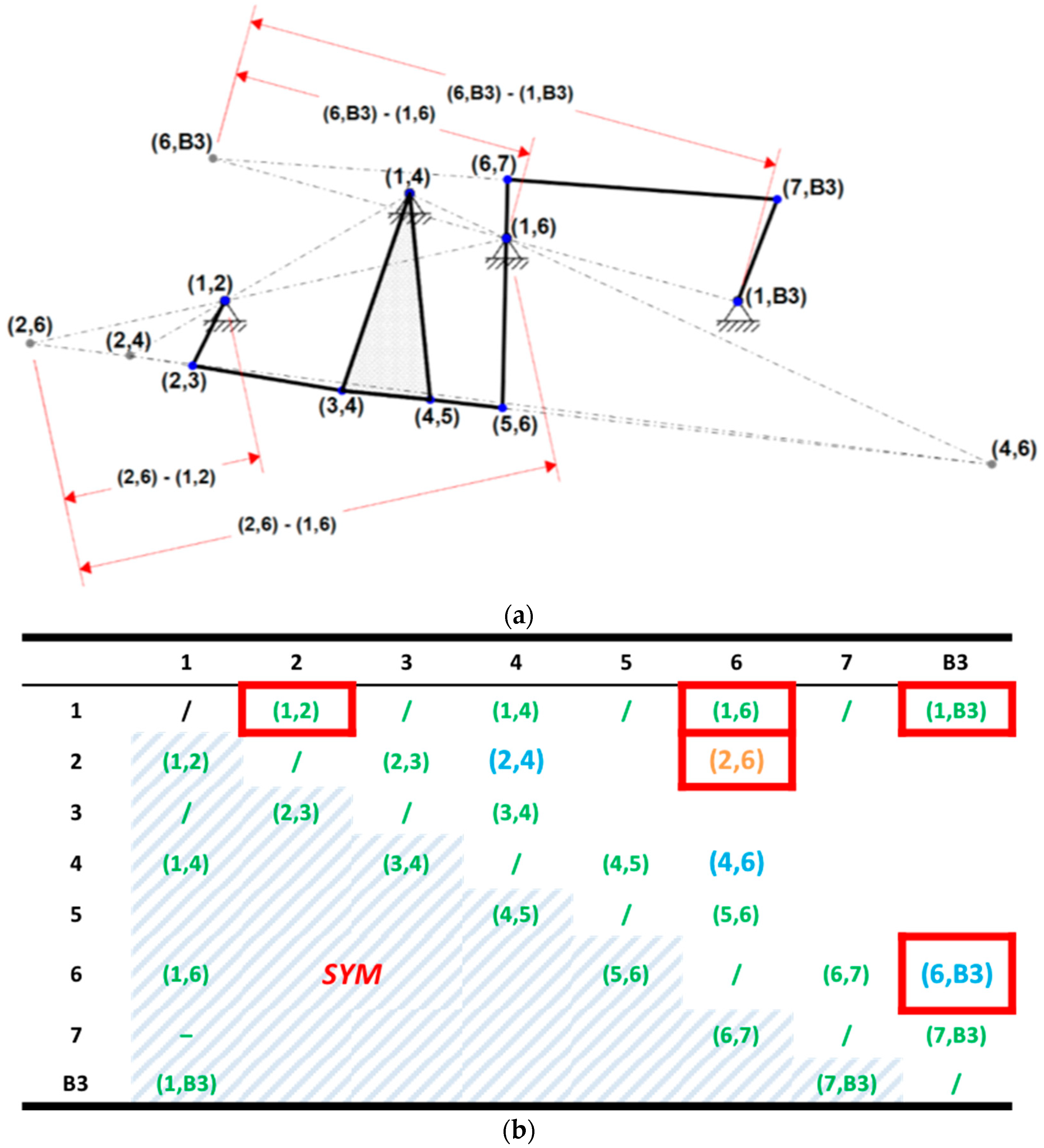
where and are the primary instant centers which respectively coincide with leverage’s fixed hinges (1, 2), (1, 6) and (1, B3). Construction of required instant centers for the inner mechanism, as shown in Figure 10a, is based on the intersection of proper Aronhold-Kennedy (AK) lines. All required ICs for the estimation of the mechanical advantage are summarized in the IC matrix of the linkage (Figure 10b).
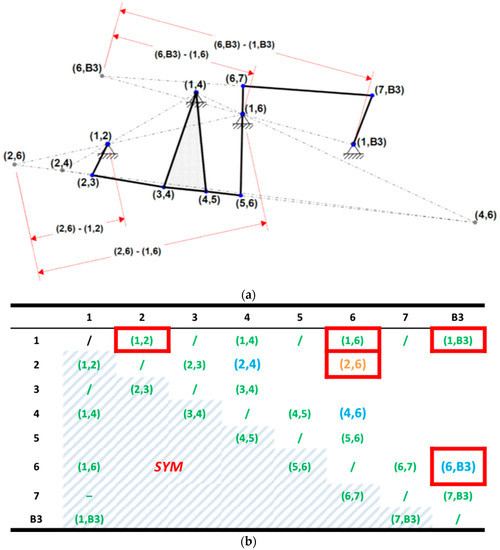
Figure 10.
Inner mechanism instant centres analysis: (a) Construction of the instant centres by means of AK lines; (b) IC matrix of the linkage: main hinges (labelled in green), first order ICs (labelled in blue), second order IC (labelled in orange) and required ICs for MA estimation (marked in red).
If the main hinges (labelled in green in Figure 10a) of the inner mechanism are defined as the output of the kinematic design process, in the first iteration the first order ICs (labelled in blue in Figure 10b) were evaluated by intersection of the respective Aronhold-Kennedy lines. In the second iteration, the second order ICs (2, 6) was finally evaluated and the mechanical advantage, for this specific linkage position, was obtained.
When the crank is activated, the rib rotates from the baseline position to the maximum downward (upward) deflection equal to +10° (−10°). During the transition from the baseline position to the target shape, for each intermediate linkage position, all required instant centres were estimated to completely obtain the mechanical advantage curve as function of the input crank rotation.
In Figure 11a, the evolution of each instant centre position is reported. The mechanical advantage for the working output angle range [+10°; −10°] is within the range [5.18; 8.97] (Figure 11b).
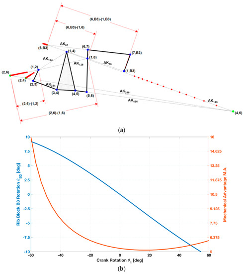
Figure 11.
Inner mechanism instant centres analysis: (a) Evolution of ICs positions for several IM configurations; (b) Mechanical Advantage and output angle curve as function of crank rotation angle.
4.3. Structural Assessment of the Inner Mechanism
To enable the transition of the Multifunctional Twistable trailing-edge concept from the reference (baseline) shape to the target ones (Mode A and B), three “active ribs” were defined along the span-wise direction: root, central and tip sections.
Each active rib has the same inner mechanism, which was synthesized to be placed within the minimum design space available in the rib block 2 (B2) of the Fowler flap. Indeed, each single degree-of-freedom (DOF) leverage is activated by a single brushless rotary motor. Therefore, the rigid rotation of the Fowler flap tab (Mode A) can be obtained by synchronizing the three actuators. On the other hand, “continuous” span-wise trailing edge twist (Mode B) can be activated providing different control actions. For example, linear span-wise flap tab twist can be enabled providing clockwise rotation to the tip actuator and anti- clockwise rotation to the root actuator.
For this reason, the geometric parameters of the leverage were synthesized in order to obtain almost linear relationship without oscillations between the crank angle and the TE angle (Figure 9a), as well as a high mechanical advantage. If the first loop design was mainly driven by kinematic performance according to the minimum available room within the Fowler flap structure, the second loop was mainly driven by the structural sizing of the links and by the mechanical arrangement definition in compliance with limit aerodynamic loads. As the actuation system was the core of the adaptive structure, reliable and accurate finite-element model were defined to simulate its kinematics, verify the preliminary design tool based on instant centres (ICs) as well as to prove its structural integrity upon limit loads. A three-dimensional finite-element model was generated; it consisted of six-faced solid elements (CHEXA [29]) for the links of the inner mechanisms and trailing edge hinge fitting and beam elements (CBEAM [29]) coupled to rigid body elements (RBE2 [29]) for the cylindrical hinges and related pins. For structural analysis purpose, the implicit nonlinear solver of MSC-NASTRAN® (SOL 400) was used to account for nonlinear effects and large displacements (rotations). The capability of the actuation system to enable morphing through smooth rigid-body kinematic of the inner mechanism was verified by applying enforced displacements (SPCD [29]) to the crank and resistant torque (equal to 160 N·m) along the hinge axis of the actuator hinge fitting. The magnitude of the enforced rotation was defined on the base of a preliminary iterative analysis finalized to get a specific rotation angle of the trailing edge. A crank rotation () equal to −35.3° was found to be required to obtain a trailing-edge rotation () equal to +5°.
Von Mises stress distribution (Figure 12b) over the actuation mechanism confirms the absence of any local plasticization at limit load condition: maximum peak stress is equal to 484 MPa and located in the “fork” link made of 17-4PH steel which in turn has a Yield Strength higher than 700 MPa. All the other leverage’s items made of aluminium, show lower stress than the Yield Strength of Al2024-T5 alloy. Finally, the actuation torque required to hold the leverage in the final position resulted equal to 23.25 N·m: the mechanical advantage resulted equal to 6.88 in accordance with the outcomes of the instant centre tool used in the preliminary design stage.
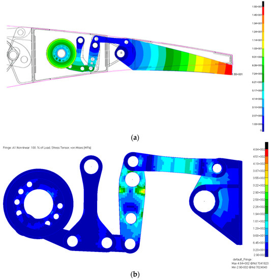
Figure 12.
Finite Element model of the Inner Mechanism: (a) Trailing-edge rotation equal to 5 degrees, Displacement distribution (mm); (b) Von Mises stress distribution (MPa).
4.4. Definition of the Mechanical Arrangement
The aeronautical needs for compactness and lightness guided the choice of the mechanical components necessary for the actuation system design. The mechanical system, shown as exploded view in Figure 13b, consists of a crank, two ternary links and three binary links. The items are connected by cylindrical hinges. The crank and the ternary links are doubly supported on the rib block 2 (B2) plates. In such a way, out-of- plane rotations of the actuation system are strongly reduced and the actuator moment is effectively transferred along the tab hinge axis. Commercial Off-the-Shelf (COTS) actuators and gearbox were considered for the finalized design.
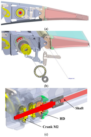
Figure 13.
Mechanical Arrangement of the Inner Mechanism: (a) Leverage within the available design space in the wing tip section, 3D-CAD (side-view); (b) 3D-CAD exploded view; (c) section view.
The Harmonic-drive® strain wave gear unit was selected because of its high-power density (gear ratio equal to 120, for CPL-17A [30]), overall dimensions and repeatability. In such a way, the torque provided by a brushless rotary motor can be amplified and transferred by the gear unit to the inner mechanism. Each rotary actuator (R1, R2 and R3) is connected to a segmented shaft which can transfer the torque to the harmonic drive gear unit of each rib. Each gear is properly joined to the rib block plate and it can transfer the torque to the crank of each inner mechanism (Figure 13c). Each crank is doubly supported by the rib plates and ball bearings were used to reduce friction between moving parts during operations.
5. Multifunctional Twistable Trailing-Edge
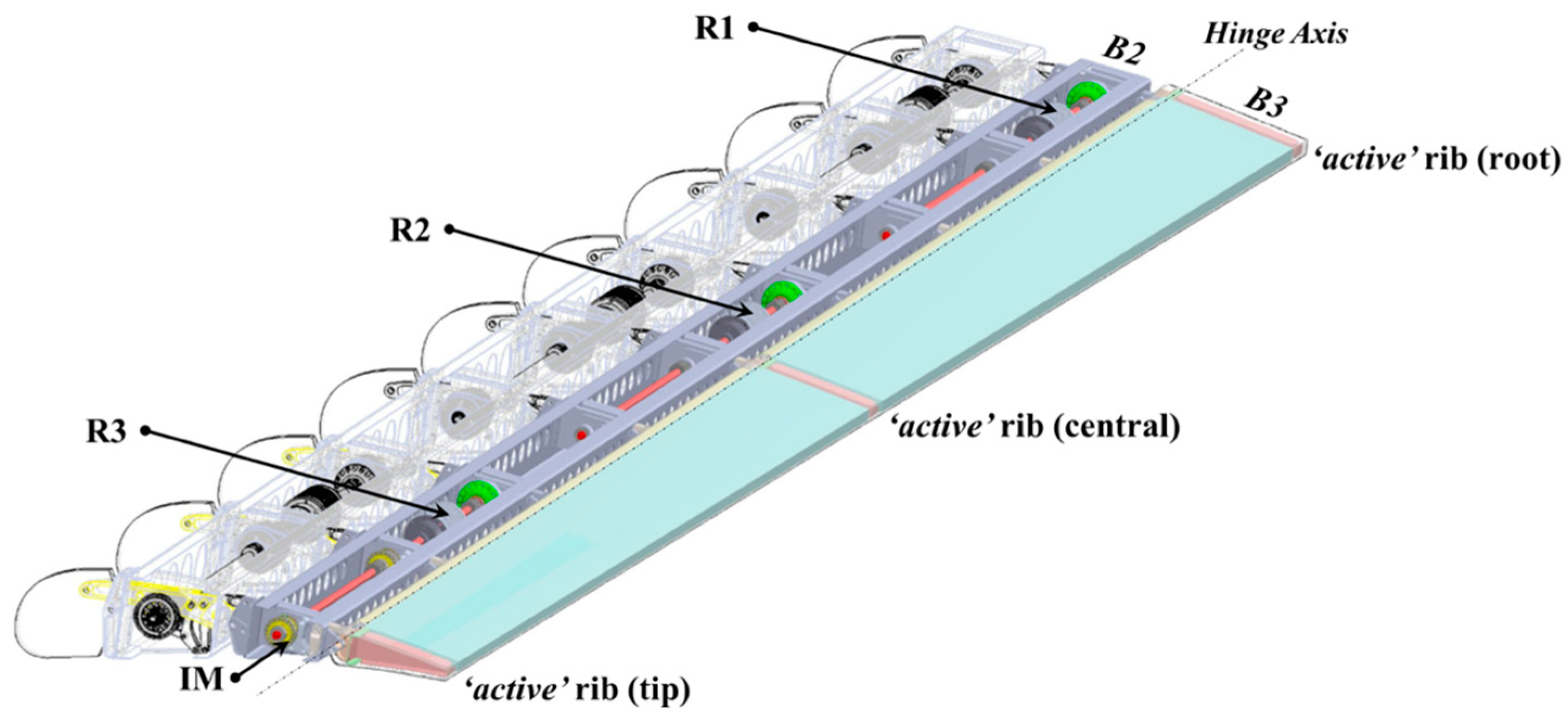
The Multifunctional Twistable TE concept is based on a thin-walled closed section beam layout (Figure 14). Three rotary actuators (placed in root, central and tip regions) transfer the torque to three independent actuation systems consisting of harmonic drive gear unit with a six-bar linkage.
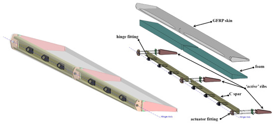
Figure 14.
Multifunctional Twistable Trailing-edge structural layout.
Control action of the TE shape can be provided by means of active ribs connected to the actuation systems with fitting and bonded to the skin. Two “c-shape” spars are bonded to the skin and connected to the Fowler flap by means of hinge fittings.
The energy required to the actuation systems to twist the trailing edge is strictly related to the geometric layout and material data. The twist of a homogeneous closed thin-walled section beam loaded by a torque Mt and that is free to warp can be evaluated according to the Bredt equation [31]:
where is the area enclosed by the mid-line of the profile’s wall and is the twist angle about the X-axis, normal to the beam section. For a homogeneous cross section, the twist in case of restrained warping can be expressed by the following differential equation [32],
where is the torsional constant of the cross section and Cω is the sectorial moment of inertia of the cross section, expressed as follows:
where is the sectorial area and t is the section thickness.
In case of tip section free to twist but warping-constrained and central section fixed (no twist nor warp), the solution of Equation (14) is given by:
The twist angle will be maximum at (tab tip section),
where the parameter is the ratio between the Saint-Venant torsion rigidity and the warping rigidity which in turn depends only on the cross-section geometry.
The parameter χ can be defined to give indication to whether the Saint-Venant torsion or warping torsion predominates [33],
For small values of χ, only warping torsion needs to be considered, however there will be a certain region for χ where neither Saint-Venant torsion nor warping torsion may be neglected and thus the structural system must be analysed for mixed torsion. If the numerator in the expression for is large as compared to the denominator, one may expect that Saint-Venant torsion is predominant. Indeed, the twist angle distribution will be described by the following equation:
and for , the maximum Saint-Venant twist angle will be:
In the above equations, the elastic moduli are related to the generic section (Figure 15) and can be obtained as integration along the section profile contour:
where s is a coordinate following the profile’s contour.

Figure 15.
Outer Trailing-edge mean geometric section.
The actuation torque to be provided by the actuation system can be preliminary estimated with Equation (17) assuming the properties of the outer tab mean geometric section, summarized in Table 2.
Table 2.
Data of the Outer Trailing-edge mean geometric section.
5.1. Assessment of the Structural Layout
The analytical model represented an effective tool to estimate main figure-of-merit and parameters during the preliminary design phase. To verify the mechanical behaviour of the multifunctional twistable trailing-edge in operative conditions, finite element (FE) simulations were instead taken in account.
A glass fibre prepreg with HexPly913 from Hexcel composites [34] was chosen as material for the upper and lower skins, the active ribs and the “C-shape” spars. This material is widely used for the manufacturing of rotor blades. Indeed, the material assures good compromise between robustness and capabilities to accommodate the large strains arising while twisting the trailing-edge.
A 3D finite-elements model was generated by using quadrilateral plane elements (CQUAD4 [29]) for the skin, C-shape spars and active ribs, while six-faced solid elements (CHEXA [29]) for the foam, actuators and hinge fittings. The numerical simulations were performed using the linear static solver of MSC-Nastran® [29]. A preliminary analysis was performed on the composite tab without aerodynamic loads to assess the maximum twisting torque required by the actuation system to implement Mode B as well as the structural strength of the twisted skin. The central “active” rib was constrained in all degrees of freedom; enforced rotations (SPCD [29]) were applied at the tip active rib (+5 degrees, “+” standing for downward) and at the root active rib (−5 degrees, “−“ standing for upward). As shown in Figure 16b, a maximum strain of about 1.34% is reached near the cut-out of the central section. For the most part of the remaining structure the strain is lower than 0.8%. According to [35], the maximum allowed strain to 2.5% along fibres direction is equal and to 0.5% along the direction perpendicular to the fibres. The torque required to enable linear twist is equal to 64.05 N·m for the tip actuation system and 103.6 N·m for the root one.
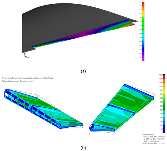
Figure 16.
Finite Element analysis with the maximum linear twist for Mode B from tip to root section (−5°/0°/+5°): (a) Displacement (mm); (b) Strain distribution, Max Principal [MicroStrain].
A second analysis was performed to prove the structural integrity of the composite structure upon the limit load condition (depicted in Figure 17) pertaining to Mode A (TE rigid rotation equal to +5 degrees downward). In such a case, all actuation systems must withstand the total aerodynamic hinge-moment pertaining to the limit load of Table 2.
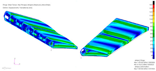
Figure 17.
Strain distribution [MicroStrain] under limit load condition.
As shown in Figure 17, a maximum strain of about 1.42% is reached near the central section. The maximum displacement is equal to 7.39 mm at the midpoint of the inboard tab region. In the remaining part of the structure, the overall displacement is below 3 mm which demonstrates sufficient stiffness of the system; in compliance with regulations (EASA CS 25.305(a)) the deformation levels do not interfere with the safe operation at limit load condition.
5.2. Estimation of Trailing-Edge Performance in Operative Conditions
According to airworthiness requirements [25], aircraft structures must withstand the limit load conditions in order to prove its structural integrity across the overall flight envelope.
However, during the regular airplane flight mission profile, load-bearing aircraft structures have to withstand aerodynamic loads lower than the ones prescribed in the limit condition.
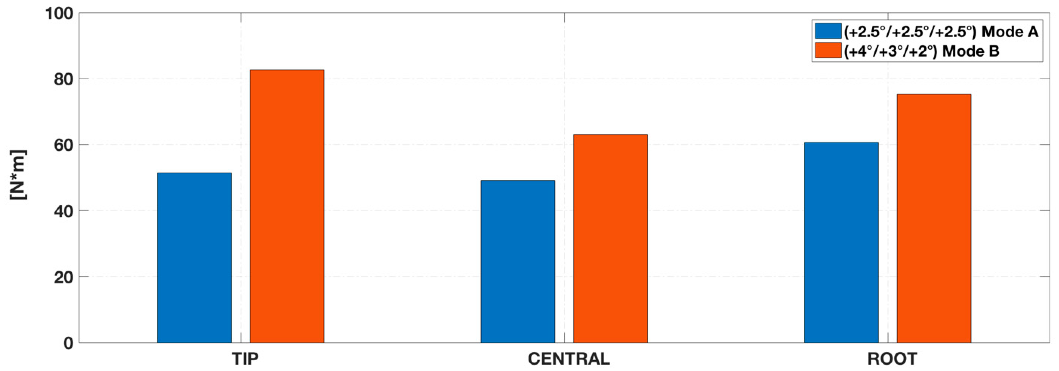
In such cases, the multifunctional twistable trailing-edge used on the AG2-NLF wing is expected to be activated in high speed climb flight conditions. To enable the transition from baseline configuration to the rigid trailing-edge deflection (mode A) equal to 2.5°, all rotary brushless motors have to be activated (R1, R2 and R3) transferring to their respective “active” ribs the same angle. In this case, the actuating torques required to enable this transition are reported in Figure 18.
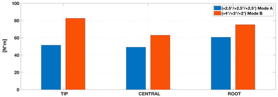
Figure 18.
Actuating torques required by the actuation systems for enabling morphing TE modes during high speed climb flight conditions ( at 4572 m).
Continuous span-wise increase in deflection angles (mode B) from tip to root can be enabled whit three independent actuation systems transferring angles equal to (4°/3°/2°) to their respective “active” ribs. Considering the aerodynamic load pertaining to the climb condition ( at 4572 m) with TE morphing in Mode B (4°/3°/2°), the structural layout shows the maximum strain equal to 0.28 per cent and the required actuating torques (per each active rib) are summarized in Figure 19.
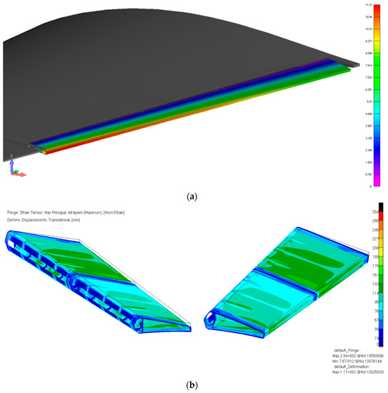
Figure 19.
TE finite element analysis with continuous increase deflection angles (Mode B) from tip to root section (+4°/+3°/+2°): (a) Displacement (mm); (b) Strain distribution, Max Principal [MicroStrain].
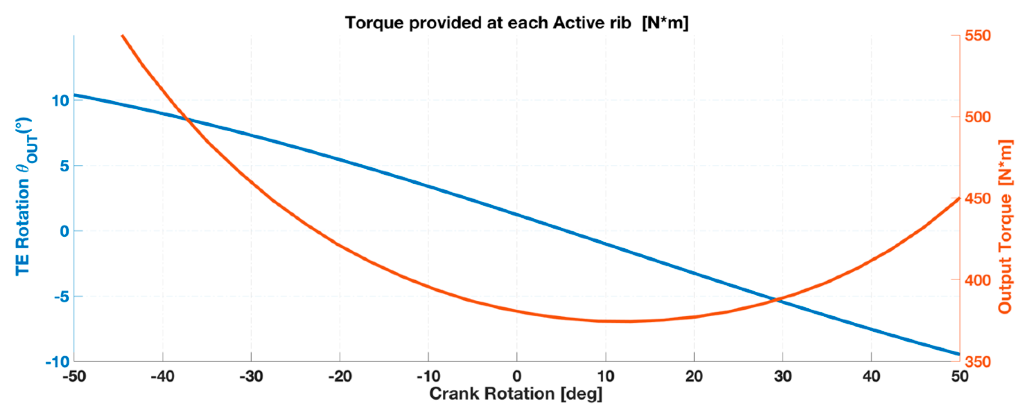
During morphing TE operations, each actuation system can provide the respective active rib with an output torque equal to
where is the torque provided by each rotary hollow-shaft brushless motor, is the gear ratio of the Harmonic Drive (CPL 17-2A) [30], is the efficiency of the Harmonic Drive and the efficiency of the inner mechanism. The output torque at each active rib can be expressed as a function of the crank position (Figure 20).
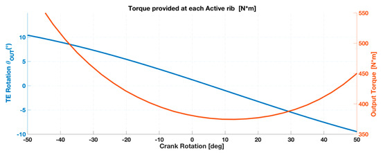
Figure 20.
Actuating torque provided by each actuation systems to its active rib during operations.
6. Conclusions
The use of a morphing system using a multifunctional twistable trailing-edge has been evaluated with reference to the NLF wing of the CLeanSky2 regional aircraft. For such subsonic aircraft, performance improvements can be expected only by recovering the loss of laminar flow that occurs at low (on the lower surface) or high (on the upper surface) values.
As concerns the wing trailing-edge, the structural and kinematic design process of the actuation system were completely addressed: three rotary brushless motors (placed in root, central and tip sections) were required to activate the inner mechanisms enabling different trailing-edge morphing modes. The structural layout of the thin-walled closed-section composite trailing-edge represents a promising concept to balance the conflicting requirements between load-carrying capability and shape adaptivity. Actuation system performances and aeroelastic deformations, considering both operative aerodynamic and limit load conditions, prove the potential of the proposed structural concept to be energy efficient and lightweight for real aircraft implementation.
Final weight of the multi-functional twistable trailing-edge is summarized in Table 3. Overall system implications have to be made with reference to the weight of a conventional outboard flap tab used for regional aircraft (Table 4).
Table 3.
Multifunctional twistable wing trailing-edge: weight breakdown.
Table 4.
Regional Turbo-Prop aircraft (90 passengers).
Retrofitting a regional aircraft with such device, a 3.52% weight increase of the outboard flap tip segment will be produced. At aircraft level, the Max Zero Fuel Weight (MZFW) will increase of 0.012% only. Finally, the mechanical power required to enable load control (LC) functionalities can be proved to be extremely affordable. Assuming the maximum resisting torque (on crank link) equal to 23.35 N·m and a crank speed rotation of 20 deg/s, the total mechanical power will be equal to 24.34 Watt for elastic twist mode (4°/3°/2°).
Author Contributions
F.R.: Conceptualization, Methodology, Software, Validation, Formal Analysis, Investigation, Resources, Data Curation, Writing-Original Draft Preparation. F.A.: Conceptualization, Methodology, Investigation, Resources, Supervision, Project Administration. R.P.: Investigation, Resources, Conceptualization, Writing-Review & Editing, Visualization, Supervision, Project Administration, Funding Acquisition. F.M.: Methodology, Software, Validation, Investigation, Visualization, Data Curation, Writing-Original Draft Preparation.
Funding
Part of the research described in this paper has been carried out in the framework of AIRGREEN2 Project, which gratefully received funding from the Clean Sky 2 Joint Undertaking, under the European’s Union Horizon 2020 research and innovation Program, Grant Agreement No. 807089—REG GAM 2018—H2020-IBA-CS2-GAMS-2017.
Acknowledgments
The authors would like to thank Leonardo Aircraft, for having provided the industrial guidelines and the necessary support to the research work addressed by this paper.
Conflicts of Interest
The authors declare no conflict of interest.
References
- High Level Group on Aviation Research. Flightpath 2050: Europe’s Vision for Aviation; European Commission: Jean-Claude Juncker, France, 2011; EUR-098-EN. [Google Scholar] [CrossRef]
- Stanewsky, E. Adaptive wing flow control technology. Prog. Aerosp. Sci. 2001, 37. [Google Scholar] [CrossRef]
- Wright, O.; Wright, W. Flying Machine. U.S. Patent No. 821393A, 22 May 1906. [Google Scholar]
- Wright, O.; Wright, W. How we Invented the Airplane: An Illustrated History; Dover Republication: New York, NY, USA, 1988; ISBN 0-486-25662-6. [Google Scholar]
- Barbarino, S.; Bilgen, O.; Ajaj, R.M.; Friswell, R.M.; Inman, D.J. A review of morphing aircraft. J. Intell. Mater. Syst. Struct. 2011, 22, 823–877. [Google Scholar] [CrossRef]
- Thornton, S.V. Reduction of Structural Loads Using Maneuver Load Control on the Advanced Fighter Technology Integration (AFTI)/F-111 Mission Adaptive Wing; NASA Technical Memorandum 4526; National Aeronautics and Space Administration: Washington, DC, USA, 1993.
- Monner, H.P. Realization of an optimized wing camber by using formvariable flap structures. Aerosp. Sci. Technol. 2001, 5, 445–455. [Google Scholar] [CrossRef]
- Woelcken, P.C.; Papadopoulos, M. Smart Intelligent Aircraft Structures (SARISTU), Proceedings of the Final Project Conference, Moscow, Russia between 19–21 May 2015; Springer: Basel, Switzerland, 2015; ISBN 978-3-319-22413-8. [Google Scholar]
- Philips, W.F. Lifting-line Analysis for twisted wings and washout-optimized wings. J. Aircr. 2004, 41, 128–136. [Google Scholar] [CrossRef]
- Phillips, W.F.; Alley, N.R.; Goodrich, W.D. Lifting-Line Analysis of Roll Control and Variable Twist. J. Aircr. 2004, 41, 1169–1176. [Google Scholar] [CrossRef]
- Griffin, K.E.; Hopkins, M.A. Smart stiffness for improved roll control. J. Aircr. 1997, 34, 445–447. [Google Scholar] [CrossRef]
- Amprikidis, M.; Cooper, J.E.; Sensburg, O. Development of an adaptive stiffness all-moving vertical tail. In Proceedings of the 45th AIAA/ASME/ASCE/AHS/ASC Structures, Structural Dynamics and Material Conference, Palm Springs, CA, USA, 19–22 April 2004. [Google Scholar]
- Ajaj, R.M.; Friswell, M.I.; Dettmer, W.G. Conceptual modeling of an adaptive torsion wing structure. In Proceedings of the 52nd AIAA/ASME/ASCE/AHS/ASC Structures, Structural Dynamics and materials Conference, Denver, CO, USA, 4–7 April 2011. [Google Scholar]
- Vu, R.; Chavez, F. Investigation of the Effects of Stiffness on Control Power via a Morphing Wing Technology. In Proceedings of the 46th AIAA/ASME/ASCE/AHS/ASC Structures, Structural Dynamics and Materials Conference, Austin, TX, USA, 18–21 April 2005. [Google Scholar]
- Vos, R.; Gurdal, Z.; Abdalla, M. Mechanism for Warp-Controlled Twist of a Morphing Wing. J. Aircr. 2010, 47, 450–457. [Google Scholar] [CrossRef]
- Werter, P.M.; Sodja, J.; Spirlet, G.; De Breuker, R. Design and Experiments of a Warp Induced Camber and Twist Morphing Leading and Trailing Edge Device. In Proceedings of the 24th AIAA/AHS Adaptive Structures Conference, AIAA Scitech, San Diego, CA, USA, 4–8 January 2016. [Google Scholar]
- Raither, W.; Heymanns, M.; Bergamini, A.; Ermanni, P. Morphing wing structure with controllable twist based on adaptive bending-twist coupling. Smart Mater. Struct. 2013, 22. [Google Scholar] [CrossRef]
- Bolonkin, A.; Gilyard, G.B. Estimated Benefits of Variable-Geometry Wing Camber Control for Transport Aircraft; NASA Technical Memorandum 20658; National Aeronautics and Space Administration: Washington, DC, USA, 1999.
- Greff, E. The development and design integration of a variable camber wing for long/medium range aircraft. Aeronaut. J. 1990, 94, 301–312. [Google Scholar]
- Cambier, L.; Heib, S.; Plot, S. The Onera eslA CFD software: Input from research and feedback from industry. Mech. Ind. 2013, 12, 159–174. [Google Scholar] [CrossRef]
- Spalart, P.R. Strategies for Turbulence Modelling and Simulation. Int. J. Heat Fluid Flow 2000, 21, 252–263. [Google Scholar] [CrossRef]
- Houdeville, R.; Bardoux, P.; Moreux, V. 3D Boundary Layer Computations on Wing-Pylon-Nacelle Configuration. In Proceedings of the Workshop on Aspects of Airframe Engine Integration for Transport Aircraft, Braunschweig, Germany, 6–7 March 1996. [Google Scholar]
- Casalis, G.; Arnal, D. ELFIN II, Sub-Task 2.3: Data Base Method. Development and Validation of the Simplified Method for Pure Crossflow Instability at Low Speed; ELFIN Technical Report No. 145; ONERA-CERT: Palaiseau, France, 1996. [Google Scholar]
- Concilio, A.; Dimino, I.; Lecce, L.; Peccora, R. (Eds.) Morphing Wing Technologies—Large Commercial Aircraft and Civil Helicopters; Chapter 5; Elsiever: Amsterdam, The Netherlands, 2017; pp. 148–154. ISBN 9780081009642. [Google Scholar]
- European Aviation Safety Agency. Certification Specifications and Acceptable Means of Compliance for Large Aeroplanes CS-25, Amendament 11; European Aviation Safety Agency: Cologne, Germany, 2011; Part C. [Google Scholar]
- Raven, F.H. Velocity and Acceleration Analysis of Plane and Space Mechanisms by Means of Independent-Position Equation. Trans. ASME J. Appl. Mech. 1958, 25, 1–6. [Google Scholar]
- Norton, R.L. Design of Machinery: An Introduction to the Synthesis and Analysis of the Mechanism and Machines, 3rd ed.; McGraw-Hill: New York, NY, USA, 2004. [Google Scholar]
- Erdmann, A.G.; Sandor, G.N.; Kota, S. Mechanism Design: Analysis and Synthesis, 4th ed.; Prentice Hall: Upper Saddle River, NJ, USA, 2001; ISBN 0-13-040872-7. [Google Scholar]
- MSC/MD NASTRAN®. Reference Manual, Software Package Version R3; MSC Software Corporation: Newport Beach, CA, USA, 2006. [Google Scholar]
- CPL-2A Component Sets Engineering Data; HarmonicDrive AG: Limburg an der Lahn, Germany, 2014.
- Bredt, R. Kritische Bemerkungen zur Drehungselastizitaat. Zeitschrift des Vereines deutscher Ingenieure 1896, 40, 813–817. [Google Scholar]
- Vlasov, V.Z. Thin-Walled Elastic Beams, 2nd ed.; Israel Program for Scientific Translation: Jerusalem, Israel, 1961. [Google Scholar]
- Kollbrunner, C.F.; Basler, K. Torsion in Structures: An Engineering Approach; Springer: Berlin, Germany, 1969. [Google Scholar]
- HexCel® Company. HexPly913 Datasheet; HexCel® Company: Stamford, CT, USA, 2016. [Google Scholar]
- Kintscher, M.; Wiedemann, M.; Monner, H.P.; Heintze, O.; Kuhn, T. Design of a smart leading-edge device for low speed wind tunnel tests in the European project SADE. Int. J. Struct. Integr. 2011, 2, 383–405. [Google Scholar] [CrossRef]


© 2018 by the authors. Licensee MDPI, Basel, Switzerland. This article is an open access article distributed under the terms and conditions of the Creative Commons Attribution (CC BY) license (http://creativecommons.org/licenses/by/4.0/).