Abstract
Low velocity impact induces barely visible damage in the form of matrix cracking or delamination that can grow under hydro-thermo-mechanical loading and possibly lead to catastrophic failure if not detected at an early stage. A network of piezoelectric transducers can be used to monitor a structure over time for life prognosis through generation and sensing of guided ultrasonic waves. The aim of this study is to design and develop such a sensing method for damage assessment in a composite T-joint subjected to mechanical impacts. In this context, monitoring of Lamb waves in a carbon fibre reinforced polymer (CFRP) T-joint has been completed where dispersion and tuning curves have been obtained. Guided waves are transmitted into the structure through different specified pairs of surface-bonded lead-zirconate-titanate (PZT) transducers in a pitch–catch active structural health monitoring (SHM) approach. With these experiments, Lamb wave fundamental modes (A0 and S0) are identified for monitoring impact damage by signal comparison with a prior obtained baseline. Detecting 4J and 10J inner impacts within the central region of the specimen is challenging when using conventional non-destructive techniques (NDT) because of the complex geometry and interference with the web. Signals are compared for the same selected sensing path; and amplitude differences have been observed in tuning curves after the 10J impact, which implies the occurrence of a structural change related to the impact.
1. Introduction
Lightweight polymer composite layered materials are used more extensively in aerospace applications as they present multiple structural advantages. However, their properties are cumbersome to evaluate because of material anisotropy. Damage and failure modes are also significantly more complicated and diverse than in metals [1], since they are occurring internally, within and between plies. Barely visible impact damage (BVID) commonly occurs from light collisions, or the dropping of hand tools. This damage can grow under hydro-thermo-mechanical loading and can possibly lead to premature catastrophic failure. Low-velocity impacts (approximately up to 10 m/s) are mostly defined as lateral loads that only induce matrix (intra-laminar) cracks and delamination (inter-laminar cracking) invisible on the surface. Impact resistance can be improved by employing less brittle polymer resins and/or introducing through-the-thickness fibre reinforcement (stitching, 3D weaving, veiling or z-pinning), resulting in higher strain to failure (absorbing larger amount of energy) [2]. Composite panels are stiffened in aircraft wings to increase flexural stiffness and strength, link structural elements and transfer load. Because of the structural discontinuity, T-joints are prone to manufacturing defects and exhibit complex damage modes. Damage may initiate in filler (junction between the web and flange) as cracks which remain invisible, and extend along flange-web and skin-flanges interface. The skin–flange debonding can then lead to delamination and ultimately fibre breakage and fracture.
Damage modes should be detected at an early stage before they propagate, reaching a critical length that can cause catastrophic failure. Hence, structural health monitoring (SHM) approaches use an integrated network of sensors to monitor the structure over time that can be used to estimate structure life and increase safety and reliability [1]. In passive sensing methods, input signals are unknown as they come from impact or acoustic emission events, which makes the identification of damage intricate. Active sensing methods interrogate the structure, sending signals from actuators to sensors. The pitch–catch method sends a signal into the structure and receives the signal affected by damage and other discontinuities across the tested material. Lead zirconate titanate (PZT) transducers are increasingly used for SHM in aerospace applications, as they are easily integrated elements that can generate and sense guided waves with good coupling capacity, rapid acquisition over time, and large area sensing without significant intrusion [1,3,4,5]. However, multiple wave modes are produced, making signal analysis and interpretation complex.
Lamb waves can be regarded as a combination of longitudinal waves and vertically polarised shear waves, which are intrinsic ultrasonic wave forms, existing in a thin plate with parallel free boundaries. Their propagation is influenced by the elastic constants, density and geometry of the material, frequency excitation, and entry angle [3]. At low frequencies, only the symmetric S0 mode and anti-symmetric A0 mode called fundamental modes exist. As velocity dispersion leads to signal complexity, methods of tuning mode have been developed for easier signal interpretation [6]. Because the S0 mode is dominated by in-plane displacement, this mode tends to travel further and is hence preferred for damage detection. However, the higher amplitude and shorter wavelength of the A0 mode—dominated by out-of-plane displacement—attract knowing that the mode wavelength must be lower than damage size [3,6,7]. The S0 mode is suitable for detection of damage in the thickness, while the A0 mode is more sensitive to surface damage [1,3]. Lamb waves are scattered by discontinuities and may generate new modes. These new generated modes can come from cracks or debonding or from structural discontinuity observed in C, I, or T shaped composite structures used in helicopter rotor blades, aircraft wings, or wind turbines [8,9,10]. Both A0 and S0 modes exhibit mode conversion to S0 mode and A0 mode respectively when interacting with a discontinuity [8,11,12,13]. Lamb waves are used for SHM because they can inspect large structures in a short time, following their curvature. Furthermore, changes in signals correspond to a particular damage presence, location, size, and severity [3]. However, damage identification for composites with Lamb waves is challenging because of propagation complexity due to composite anisotropy, superposition of waves reflected and transmitted due to their fast velocities, noises, mode conversion, multi-mode presence, and dispersive nature. All guided waves problems are associated with appropriate dispersion curves, and signals must be processed and interpreted [3,7,14,15]. Features are extracted from signals in time domain, frequency domain (through fast Fourier transform (FFT)) and joint time-frequency domain (wavelet transform) and are compared for pristine and damaged structures. For this method, a baseline of the signal is previously obtained and stored; and a threshold value must be estimated to identify when the signal changes comes from damage and not noises. Sufficiently large structures without discontinuities are preferred as modes are more easily separated, however carbon fibre reinforced polymer (CFRP) aerospace structures are more complex, including many discontinuities [16] and high attenuation ratio [3,7,17]. Transducer positions benefiting of shorter actuator–sensor distances can overcome attenuation and wave reflections; actuators bounded close to an edge can also reduce wave reflections [16,18].
Previous studies on damage detection are difficult to reproduce as these methods are still dependent on material anisotropy, geometry, data acquisition system, and sensor type. The complex geometry of T-joints involves multiple reflections and mode conversions from discontinuities [8] and thickness change effects affecting modes velocities [9]. It is therefore crucial to compare signal responses for the same path before and after damage [16]. Adding T-stringers on a composite panel usually increases signal damping [3,16,19]. Most studies on SHM of T-joints induced damage under tensile loading [20,21,22,23] or under three point bending [24,25,26] and performed damage detection by considering changes in amplitude responses [22,23,25,26]. Wu [22] rapidly monitored delamination occurrence and extension tendency using the S0 tuned mode with few direct paths during loading; and after loading, damage shape, and severity are effectively determined by damage imaging diagnosis. Although embedded delamination is easier to detect, this combination of methods has been verified on a full-scale aircraft tail under loading. Delamination or interface debonding involves thickness reduction (laminate split into two sub-laminates) which affects dispersion curves (and thus mode velocities) and significantly reduces propagating energy and signal amplitude [9,25,26,27,28]. According to Kapoor et al. [25], damage in filler regions involves mode conversion from A0 to S0, which has been captured by Swenson et al. [26] after passing the filler. Ma et al. [23] introduced an amplitude damage index with the A0 tuned mode that effectively monitors during loading different damage occurrences: filler crack, interface debonding, and ultimate failure have been detected respectively by a slight reduction in amplitude, a mode conversion from A0 to S0, and a sharp drop of amplitude. However, the identification of these damage modes with high speed camera can be questioned as the camera cannot really pick up damage evolution inside the sample.
Therefore, the main area of investigation for further improvement in this field would be the effective identification of damage, validated by conventional non-destructive techniques (NDT) and the development of a predictive model that can estimate the strength after impact. Multiple SHM techniques using Lamb waves have been developed to detect damage in non-accessible locations, but inspection of large structures is time-consuming and costly. Thus, inspection of hot spots such as C, I, or T shaped regions can be established for efficient monitoring. Challenges in this type of structure when using Lamb waves-based damage identification are thickness change effects, multiple reflections and mode conversions (from free edges and web-flange interface), which require careful wave propagation analysis [23,25,27]. In this article, a T-shaped CFRP specimen is monitored with nine surface-mounted piezoelectric transducers. Different low velocity impacts have been performed; and signals are compared before and after loading through signal processing and analysis. The dispersion and tuning curves (group velocities and amplitudes) are obtained and used to successfully detect damage.
2. Materials and Methods
2.1. Materials
A CFRP T-joint used for aircraft wing box applications has been monitored using nine PZT transducers. The composite is made of six plies of 5H satin woven fabric carbon fibres Hexcel Injectex G0926 and epoxy resin Hexcel RTM6. The sample is 2 mm thick with the dimensions shown in Figure 1 and density about 1400 kg/m3. PZT transducers P-876.SP1 DuraAct from PI Ceramic Piezo Technology (0.3 g and 16 × 13 × 0.5 mm3) are used to generate and sense Lamb waves. They operate mainly in longitudinal mode (wave propagation preferentially oriented in the length direction of the PZT patch [1]), allowing monitoring directly the tricky filler region of the T-joint. Transducers are evenly surface mounted on each side of the skin and on the web in order to cover all the part. They are positioned at the edges of the sample and at short enough distances to each other to reduce wave reflections [16,18].
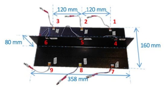
Figure 1.
Geometry of the CFRP T-joint sample with attached PZT transducers.
2.2. Theoretical Dispersion Curves
Group velocities depend on the frequency excitation, elastic constants, density, and geometry of the material; they can be calculated with the Rayleigh–Lamb equation [7]. Several methods are used to establish these curves in theory. For multi-layered composite plates, they are obtained by analytical tools such as transfer matrix or global matrix approaches. The higher the frequency–thickness product is, the more different modes will exist simultaneously superposed [3]. By combining the elastic properties of the woven fabric and the resin according to the fibre volume fraction, lamina properties, and subsequently composite stiffness matrix can be evaluated and used for theoretical analysis of mode velocity. The SAFE_DISPERSION [29] program has been used to obtain the theoretical dispersion curves shown in Figure 2. However, these theoretical curves are obtained considering the damping ratio null. Furthermore, each woven fabric ply is considered as two plies of perpendicular directions and assumed isotropic. The composite is thus considered with the following stacking sequence: (+45/−45/90/0/−45/+45)s.
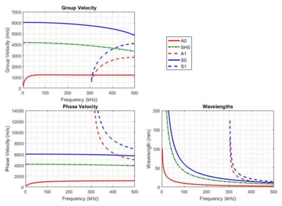
Figure 2.
Theoretical dispersion curves for a quasi-isotropic CFRP plate (+45/−45/90/0/−45/+45)s.
2.3. Guided Wave Experiments
Guided waves are transmitted into the structure through different pairs of PZT transducers in a pitch–catch configuration. A baseline has been firstly obtained by transmitting a signal to each of the transducers, one by one, and receiving signals from each other transducer. Afterwards, the same process of signal acquisition has been done after each different set of impacts.
For damage identification context, the parameters of the Lamb wave sent to the structure can be optimised to reduce wave dispersion effect [1,3]. By concentrating the energy within a narrow frequency range, wave dispersion can be controlled. Pure sinusoidal shapes excite Lamb wave harmonics more efficiently. The tone-burst sinusoidal signal is windowed to get a narrow bandwidth by using a window function, such as the Hanning function commonly used in SHM applications, and centralize energy [19,30]. The bandwidth can also be reduced by increasing the number of cycles; however, it results in unavoidable increased overlapping of wave components [3,31]. For our guided waves experiments, a three-tone-burst sinusoidal signal is used with a Hanning window, described as the following equation, for a frequency f and NBurst burst number (three),
In order to overcome Lamb wave attenuation, the generated three-tone-burst sinusoidal signal has been amplified to 100 Vpp (peak-to-peak voltage). The input signal is triggered every 10 milliseconds to allow previous excitation to damp out and not contaminate the next response. For the dispersion and tuning curves, the received signal is also amplified and an averaging of 100 acquisitions is obtained to experimentally get a smoother signal. For the complete damage investigation, the signals for the baseline and after the impact event are obtained with an averaging of 500 acquisitions.
2.4. Dispersion and Tuning Curves Determination Method
Dispersion and tuning curves must be determined and each mode present in the signal must be identified. Each direct path on the skin (1–7; 2–8; 3–9) and path between skin and web (1–4; 2–5; 3–6; 7–4; 8–5; 9–6), as represented Figure 3, has been tested over a wide range of frequencies (20 to 500 kHz every 5 kHz). The distance between these transducers (from a transmitter T to a receiver R) is 130 mm. Fundamental modes A0 and S0 have been identified by determining velocities of the different packets at different frequencies. The envelope of the signal is obtained using Hilbert transform and smoothed with a low pass filter. Peaks of each wave packet are extracted; and their amplitude and time of flight (ToF) are obtained. ToF is defined as the difference between the time of the received signal peak and the time of the generated signal peak as explained with Figure 4. The group velocity Cg (m/s) is then calculated according to the distance between sensors d (m) and the ToF (s) with the equation:

Figure 3.
Schematic representation of paths: (a) on skin, from ‘T8’ to ‘R2’; and (b) on web, from ‘T8’ to ‘R5’.
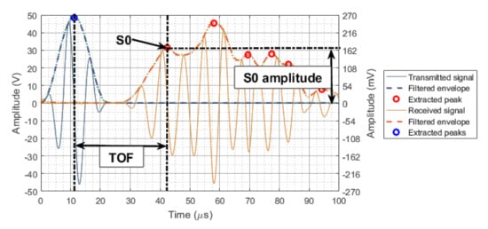
Figure 4.
Determination of time of flight and amplitude for the S0 mode at 135 kHz for a signal transmitted from ‘T8’ and received by ‘R2’.
Finally, dispersion curves and tuning curves are obtained by plotting respectively group velocities and amplitudes of each mode as function of frequency.
2.5. Impact Damage Initiation
In order to introduce barely visible (mostly internal) damage in the specimen, low velocity impacts have been achieved on the flat surface of the T-joint (Figure 1). An Instron impact tower has been used for the drop weight testing and a specific fixture had to be created, as shown in Figure 5a. Two different sets of impact have been performed:
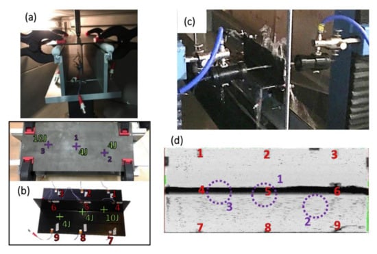
Figure 5.
(a) Impact testing configuration with the impactor and the T-joint fixed on its support in the chamber of the impact tower; (b) Locations of the three impacts: first impact of 4J in the middle, second impact of 4J and third impact of 10J; (c) Water jet probe inspection system; (d) C-scan of the T-joint after three impacts, with locations of impact (in purple) and of PZTs (in red).
- A first impact of 4J has been introduced under the web in the middle of the T-joint, at location ‘1’ shown in Figure 5b, and guided waves signals have been collected afterwards. Some results of signal comparison between the pristine structure and after this 4J impact are presented in the following section.
- Then, two more impacts at different locations have been executed: an impact of 4J slightly offset from the web of the T-joint approximately between transducers ‘3’ and ‘9’ at location ‘2’ presented in Figure 5b and an impact of 10J under the web of the T-joint approximately between transducers ‘1’ and ‘7’ at location ‘3’ as shown in Figure 5b. Guided waves signals have been collected afterwards and some results of signal comparison between the pristine structure and after these three impacts are discussed in Section 3.
Ultrasonic C-scans were performed after each impact with a water jet probe inspection system from Midas-NDT as shown in Figure 5c. The C-scan shown in Figure 5d does not show any obvious damage in the T-joint. Performing a water jet probe inspection in a T-shaped structure is challenging because the web of the T-joint produces a shadow that prevents a clear image of the impact induced damage. Moreover, this inspection system creates water droplets, splashed over the structure, which may obscure the damage further. None of the impacts are visible on the specimen surface.
3. Results and Discussion
3.1. Identification of Lamb Waves Fundamental Modes
Guided waves experiments have been completed in order to identify the different wave modes present in the received signal and obtain the dispersion and tuning curves. In this context, the received signal is amplified by ten and an averaging of 100 acquisitions is obtained to get smoother signals. At low frequencies, the first mode received is the A0 mode with maximum amplitude of 340 mV at 30 kHz, confirmed by fast Fourier transforms (FFTs). Then, this mode progressively disappears and a new wave packet is visible around 50 kHz. This new first arrival mode is the S0 mode with maximum amplitude of 170 mV around 135 kHz for direct paths on the skin; and 110 mV around 180 kHz for paths between skin and web (Figure 3). According to similar experiments in the literature, fundamental modes A0 and S0 have been tuned at respective frequencies of 100 kHz and 250–300 kHz [8,22,23,24,25,26,27,32], which is in agreement with the present set-up.
These fundamental modes are presented in Figure 6 as received signals and in Figure 7 as dispersion and tuning curves. Once the S0 mode appears, the A0 mode is difficult to identify due to fast reflections of the fast S0 mode from the free edges of the specimen. The S0 mode is followed by a wave packet with higher amplitude corresponding either to the SH0 (shear horizontal) mode according to the theoretical group velocity (Figure 2) or to the mode converted S0A0 which could be generated by the interaction of the S0 mode with the web of the T-joint. For signals travelling between the skin and the web, the S0 mode amplitude is considerably lower. According to the theoretical curves, new modes known as A1 and S1 should appear but are not identified in such a small specimen subjected to mode superposition due to wave reflections from free edges [28]. Thus, first arrival modes, which are the fundamental modes, are preferentially selected for this study.
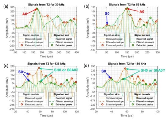
Figure 6.
Identification of A0 and S0 modes for signals transmitted from ‘T2’ and received on skin by ‘R8’ and on web by ‘R5’ at frequencies: (a) 30 kHz; (b) 55 kHz; (c) 135 kHz; and (d) 180 kHz.
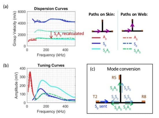
Figure 7.
Experimental (a) dispersion and (b) tuning curves for paths on skin and web; (c) Mode conversions at structural discontinuity of a T-joint for S0 mode transmitted from PZT ‘T2’ and received by PZTs ‘R8’ on skin and ‘R5’ on web.
3.2. Dispersion and Tuning Curves
The dispersion and tuning curves plotted in Figure 7 are obtained during the first guided waves experiments, where the received signals have been amplified by ten and averaged with 100 acquisitions. Different paths have been selected and compared:
The dispersion curves plotted in Figure 7a show no obvious difference of velocities by comparing paths on the skin and on the web. However, tuning curves plotted in Figure 7b show lower amplitude of the S0 mode and the mode converted S0A0 for paths on the web than paths on the skin. The guided wave loses amplitude by travelling through the curvature of the material.
The A0 mode and S0 mode have respectively a group velocity of approximately 1000 m/s and 4500 m/s (Figure 7a) at low frequencies (non-dispersive region), which is in good agreement with the values expected from the literature [3,7,10,13,27,30]. However, higher velocities were expected according to the theoretical dispersion curves plotted in Figure 2. This difference is due to various approximations made to calculate these theoretical curves, like the isotropic assumption and above all, the damping considered null. The experimental curves are also subjected to experimental disturbances and errors from the tools used (guided waves equipment, PZT transducers, composite specimen) and the low precision coming from the low amplitude of the received signal.
The group velocity of the wave packet with higher amplitude previously introduced as either the SH0 mode or the mode converted S0A0 is represented in thin lines in dispersion curves of Figure 7a. The complex geometry of the T-joint suggests the probability of mode conversion by interaction with the web discontinuity, as represented in Figure 7c. Assuming this mode is the converted S0A0, the group velocity can be easily recalculated by considering it has been generated near the web, at a distance of 65 mm from the PZT receiver (web-receiver) instead of 130 mm (transmitter-receiver), which is half the distance (Figure 1). The recalculated group velocity corresponds to the A0 mode velocity (1000 m/s); therefore, this mode can be considered as the mode converted S0A0 created in the filler region of the T-joint.
3.3. Signal Comparison between the Baseline and Signal Acquired after a 4J Impact
In the context of BVID investigation, all signals of all sensing paths (transducers pairs) possible have been acquired; and the received signals for the baseline and for after impacts have been averaged with 500 acquisitions. Signals for the same transducers path are compared to minimize effect from other factors. The first set of impact implies a 4J impact in the middle of the T-joint, not visible by the naked eye. In order to study this particular impact, only PZT transducers ‘2’, ‘5’, and ‘8’ can be considered (Figure 1). Dispersion and tuning curves have been obtained after impact and compared with the curves obtained for the baseline. The results are shown in Figure 8. The sensing paths selected should directly interact with the impact; however, no obvious changes have been observed between the curves before and after the impact. Group velocities in Figure 8a for the A0, the S0 or the S0A0 modes remain similar. On the tuning curve Figure 8b of the path ‘T8R5’ corresponding to signal travelling from a PZT on the skin to a PZT on the web, a slight reduction of amplitude can be detected for the S0 mode; whereas amplitudes of the S0 mode remain unchanged for signal travelling to a PZT on the skin (‘T8R2’). The S0A0 mode converted undergoes likewise slight amplitude reduction after impact.
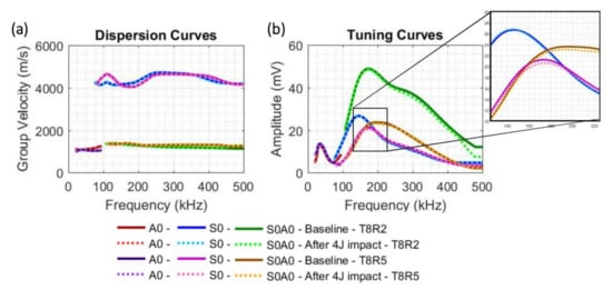
Figure 8.
(a) Dispersion and (b) tuning curves comparison between the baseline and signals acquired after a 4J impact in the middle of the T-joint, for signals generated from transmitter ‘T8’ and received by receivers ‘R2’ (path on skin) and ‘R5’ (path on web).
FFTs of signals generated at different frequencies (from 20 to 500 kHz) have been calculated and compared before and after the 4J impact. According to the theoretical and experimental dispersion curves of Figure 2 and Figure 7 respectively, the A0 mode is the only mode present at 30 kHz. The FFT of the signal generated at 30 kHz from transmitter ‘T8’ is plotted in Figure 9a for paths on skin and on web. A lower spectrum magnitude is observed after impact, which suggests a difference in the signal for the A0 mode. The FFT of the signal generated at 150 kHz plotted in Figure 9b also shows some signal differences between signals acquired before and after impact. The differences observed in the tuning curves (Figure 8) and in the FFTs (Figure 9), even though subtle, imply the occurrence of a structural change in the T-joint at the location of the impact, in the paths from transducer ‘2’ to transducers ‘5’ and ‘8’.
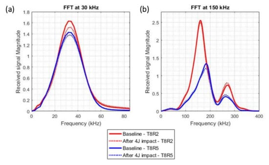
Figure 9.
Comparison of FFTs of signals generated at (a) 30 kHz and (b) 150 kHz from transmitter ‘T8’ and received by receivers ‘R2’ (path on skin—in red) and ‘R5’ (path on web—in blue), for the baseline and for signals acquired after a 4J impact in the middle of the T-joint.
3.4. Signal Comparison between the Baseline and Signal Acquired after a 10J Impact
The second set of impact implies a 4J impact and a 10J impact, which are not visible on the surface of the T-joint. This second 4J impact has not been studied yet. In order to study the 10J impact, only PZT transducers ‘1’, ‘4’, and ‘7’ can be considered (Figure 1). The sensing paths selected should directly interact with the 10J impact. Dispersion and tuning curves have been obtained after impacts and compared with the curves obtained for the baseline. The results are shown in Figure 10. Changes in velocities and amplitudes are clearly observed for the S0 mode and the S0A0 mode converted. Therefore, the 10J impact can be easily detected with the S0 mode and involve more signal differences than the 4J impact as previously studied, suggesting that BVID can be quantified. According to the tuning curves in Figure 10b, the S0 mode undergoes amplitude reduction when travelling on the skin (path ‘T7R1’), whereas amplitudes appear higher after impact when travelling on the web (path ‘T7R4’). Amplitudes of the A0 mode are also slightly reduced.
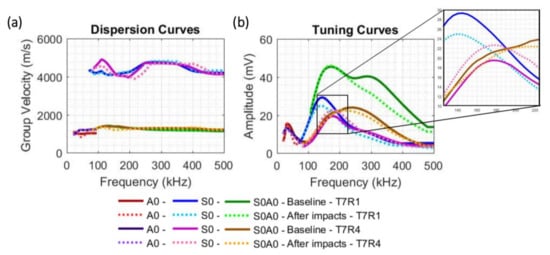
Figure 10.
(a) Dispersion and (b) tuning curves comparison between the baseline and signals acquired after a 10J impact, for signals generated from transmitter ‘T7’ and received by receivers ‘R1’ (path on skin) and ‘R4’ (path on web).
3.5. Discussion
This damage detection method based on dispersion curves can be further improved in terms of computational time and damage identification with further advancement in computation method and analysis algorithm in order to be more competitive and practical in real applications. For instance, a proper damage index could be implemented to evaluate damage severity. ToFs, amplitudes, and FFTs of both the A0 mode (below 100 kHz) and S0 mode (100 to 500 kHz) should be considered as they contain different damage information [13]. As previously observed, amplitude variations after a 10J impact could directly allow damage detection, whereas amplitudes were not clearly changed after a 4J impact and FFTs were required to detect the damage occurrence. The particular amplitude changes observed after the 10J impact should be further analysed through finite element model analysis and experimentally with laser scanning vibrometer (LSV) techniques, which could identify mode conversion [32]. Delamination is usually identified by analysing mode conversion [14,28], however the presence of stringer in the T-joint implies reflections, mode conversions and signal damping [32]. Different impact parameters have still to be identified through appropriate algorithm development [15] and machine learning. Additional signal filtering would allow extracting the information needed and thus make computational work faster [14,33]. For damage localisation, ToFs accuracy can be improved by analysing wave attenuation and eventual ambient conditions effect [13,34].
4. Concluding Remarks
By monitoring Lamb waves at different frequencies using piezoelectric PZT transducers in a composite T-joint, fundamental modes (A0 and S0) have been identified. Dispersion and tuning curves have been used to understand the wave propagation. As mode velocities are functions of the frequency excitation, the material geometry, density, and the elastic constants, a change in one of these parameters will modify the curves and can hence be used for damage assessment. The A0 and S0 modes can be tuned approximately at 30 kHz and 150 kHz respectively, which allows detecting particular structural changes with easier interpretation. Signals have been obtained for all sensing paths to create a baseline, corresponding to the pristine structure.
BVID was induced in the T-joint through two impact energies, of 4J and 10J, at different locations. Detecting BVID within the central region of the specimen is challenging when using conventional NDT because of the complex geometry which creates a shadow from the web. However, by comparing and analysing Lamb wave signals between the pristine structure and the damaged structure, BVID can be detected. The 10J impact involves more signal differences than the 4J impact; thus a damage index based on ToFs and amplitudes can be developed to quantify BVID. Another appropriate NDT for T-shaped structure should also be used to validate damage identification. Defects can be further localised through the implementation of the network of the ultrasonic transducers.
Acknowledgments
The coauthor Kui Yao acknowledges partial support by Singapore Maritime Institute under the Asset Integrity & Risk Management (AIM) R&D Programme, Project ID: SMI-2015-OF-01, and IMRE/15-9P1115.
Author Contributions
The author Marilyne Philibert conceived and performed the experiments, analysed the data, and wrote the paper; the co-authors Constantinos Soutis and Matthieu Gresil provided supervision, and contributed to the analysis and critical technical discussions; the co-author Kui Yao contributed to the analysis and technical discussion.
Conflicts of Interest
The authors declare no conflict of interest.
References
- Giurgiutiu, V. Structural Health Monitoring of Aerospace Composites; Academic Press: Waltham, MA, USA, 2016; ISBN 9780124096059. [Google Scholar]
- Richardson, M.O.W.; Wisheart, M.J. Review of low-velocity impact properties of composite materials. Compos. Part A Appl. Sci. Manuf. 1996, 27, 1123–1131. [Google Scholar] [CrossRef]
- Su, Z.; Ye, L. Identification of Damage Using Lamb Waves: From Fundamentals to Applications; Springer Science & Business Media: Berlin, Germany, 2009; Volume 48, ISBN 9781848827837. [Google Scholar]
- Balageas, D.; Fritzen, C.; Güemes, A. Structual Health Monitoring; Wiley-ISTE: London, UK, 2006; ISBN 9781905209019. [Google Scholar]
- Gresil, M.; Giurgiutiu, V. Guided wave propagation in composite laminates using piezoelectric wafer active sensors. R. Soc. Aeronaut. J. 2013, 117, 971–995. [Google Scholar] [CrossRef]
- Diamanti, K.; Soutis, C. Structural health monitoring techniques for aircraft composite structures. Prog. Aerosp. Sci. 2010, 46, 342–352. [Google Scholar] [CrossRef]
- Rose, J.L.; Morrow, P. An Introduction to Ultrasonic Guided Waves. In Proceedings of the 4th Middle East NDT Conference and Exhibition, Manama, Kingdom of Bahrain, 2–5 December 2007. [Google Scholar]
- Ramadas, C.; Balasubramaniam, K.; Joshi, M.; Krishnamurthy, C.V. Interaction of Lamb mode (Ao) with structural discontinuity and generation of “turning modes” in a T-joint. Ultrasonics 2011, 51, 586–595. [Google Scholar] [CrossRef] [PubMed]
- Ramadas, C.; Balasubramaniam, K.; Joshi, M.; Krishnamurthy, C.V. Sizing of interface delamination in a composite T-joint using time-of-flight of Lamb Waves. J. Intell. Mater. Syst. Struct. 2011, 22, 757–768. [Google Scholar] [CrossRef]
- Chakrapani, S.K.; Barnard, D.; Dayal, V. Finite element simulation of core inspection in helicopter rotor blades using guided waves. Ultrasonics 2015, 62, 126–135. [Google Scholar] [CrossRef] [PubMed]
- Soorgee, M.H. A mode conversion based feature for crack depth evaluation in homogenous plates based on 3D simulated Lamb waves. In Proceedings of the 3rd Iranian International NDT Conference, Tehran, Iran, 21–22 February 2016. [Google Scholar]
- Benmeddour, F.; Grondel, S.; Assaad, J.; Moulin, E. Study of the fundamental Lamb modes interaction with asymmetrical discontinuities. NDT E Int. 2008, 41, 330–340. [Google Scholar] [CrossRef]
- Quaegebeur, N.; Micheau, P.; Masson, P.; Maslouhi, A. Structural health monitoring strategy for detection of interlaminar delamination in composite plates. Smart Mater. Struct. 2010, 19, 085005. [Google Scholar] [CrossRef]
- Testoni, N.; de Marchi, L.; Marzani, A. Detection and characterization of delaminations in composite plates via air-coupled probes and warped-domain filtering. Compos. Struct. 2016, 153, 773–781. [Google Scholar] [CrossRef]
- Monaco, E.; Boffa, N.D.; Memmolo, V.; Ricci, F.; Testoni, N.; De Marchi, L.; Marzani, A.; Hettler, J.; Tabatabaeipour, M.; Delrue, S.; et al. Methodologies for Guided Wave-Based SHM System Implementation on Composite Wing Panels: Results and Perspectives from SARISTU Scenario 5. In Smart Intelligent Aircraft Structures (SARISTU); Springer: Cham, Switzerland, 2016; pp. 495–527. [Google Scholar]
- Janarthan, B.; Mitra, M.; Mujumdar, P.M. Damage detection in stiffened composite panels using Lamb wave. In Proceedings of the 6th European Workshop on Structural Health Monitoring (EWSHM 2012), Dresden, Germany, 3–6 July 2012; Volume 2, pp. 1033–1041. [Google Scholar]
- Gresil, M.; Giurgiutiu, V. Prediction of attenuated guided waves propagation in carbon fibre composites using Rayleigh damping model. J. Intell. Mater. Syst. Struct. 2015, 26, 2151–2169. [Google Scholar] [CrossRef]
- Lee, B.C.; Staszewski, W.J. Sensor location studies for damage detection with Lamb waves. Smart Mater. Struct. 2007, 16, 399–408. [Google Scholar] [CrossRef]
- Su, Z.; Ye, L.; Lu, Y. Guided Lamb waves for identification of damage in composite structures: A review. J. Sound Vib. 2006, 295, 753–780. [Google Scholar] [CrossRef]
- Kesavan, A.; Deivasigamani, M.; John, S.; Herszberg, I. Damage detection in T-joint composite structures. Compos. Struct. 2006, 75, 313–320. [Google Scholar] [CrossRef]
- Kesavan, A.; John, S.; Herszberg, I. Strain-based Structural Health Monitoring of Complex Composite Structures. Struct. Health Monit. 2008, 7, 203–213. [Google Scholar] [CrossRef]
- Wu, Z.; Gao, D.; Wang, Y.; Rahim, G. In-service structural health monitoring of a full-scale composite horizontal tail. J. Wuhan Univ. Technol. Sci. Ed. 2015, 30, 1215–1224. [Google Scholar] [CrossRef]
- Ma, X.; Bian, K.; Lu, J.; Xiong, K. Experimental Research on Detection for Interface Debond of CFRP T-joints under Tensile Load. Compos. Struct. 2016, 158, 359–368. [Google Scholar] [CrossRef]
- Kapoor, H.; Soni, S.R. Experimental structural health monitoring of Z-fibre reinforced co-cured composite pi-joints using Lamb wave propagation. In Proceedings of the SPIE—Nondestructive Characterization for Composite Materials, Aerospace Engineering, Civil Infrastructure, and Homeland Security, San Diego, CA, USA, 8–12 March 2009; Volume 7294, pp. 1–9. [Google Scholar] [CrossRef]
- Kapoor, H.; Blackshire, J.L.; Soni, S.R. Damage detection in z-Fibre reinforced, co-cured composite Pi-Joint using pitch–catch ultrasonic analysis and scanning laser vibrometry. Struct. Longev. 2010, 3, 221–238. [Google Scholar]
- Swenson, E.D.; Soni, S.R.; Kapoor, H. Lamb wave propagation in Z-pin reinforced co-cured composite pi-joints. Proc. SPIE 2010, 7649, 76490D. [Google Scholar] [CrossRef]
- Geetha, G.K.; Mahapatra, D.R.; Gopalakrishnan, S.; Hanagud, S. Laser Doppler imaging of delamination in a composite T-joint with remotely located ultrasonic actuators. Compos. Struct. 2016, 147, 197–210. [Google Scholar] [CrossRef]
- Okabe, Y.; Fujibayashi, K.; Shimazaki, M.; Soejima, H.; Ogisu, T. Delamination detection in composite laminates using dispersion change based on mode conversion of Lamb waves. Smart Mater. Struct. 2010, 19, 115013. [Google Scholar] [CrossRef]
- LAMSS (Laboratory for Active Materials and Smart Structures) and University of South Carolina. SAFE_DISPERSION_GUI. 2014. Available online: http://www.me.sc.edu/research/lamss/html/software.html (accessed on 1 June 2017).
- Wang, X.; Lu, Y.; Tang, J. Damage detection using piezoelectric transducers and the Lamb wave approach: I. System analysis. Smart Mater. Struct. 2008, 17, 1–15. [Google Scholar] [CrossRef]
- Kessler, S.S.; Spearing, S.M.; Soutis, C. Damage detection in composite materials using Lamb wave methods. Smart Mater. Struct. 2002, 11, 269–278. [Google Scholar] [CrossRef]
- Sherafat, M.H.; Guitel, R.; Quaegebeur, N.; Hubert, P.; Lessard, L.; Masson, P. Structural health monitoring of a composite skin-stringer assembly using within-the-bond strategy of guided wave propagation. Mater. Des. 2016, 90, 787–794. [Google Scholar] [CrossRef]
- Si, L.; Wang, Q. Rapid multi-damage identification for health monitoring of laminated composites using piezoelectric wafer sensor arrays. Sensors (Switzerland) 2016, 16, 638. [Google Scholar] [CrossRef] [PubMed]
- Kijanka, P.; Radecki, R.; Packo, P.; Staszewski, W.J.; Uhl, T. GPU-based local interaction simulation approach for simplified temperature effect modelling in Lamb wave propagation used for damage detection. Smart Mater. Struct. 2013, 22, 035014. [Google Scholar] [CrossRef]
© 2018 by the authors. Licensee MDPI, Basel, Switzerland. This article is an open access article distributed under the terms and conditions of the Creative Commons Attribution (CC BY) license (http://creativecommons.org/licenses/by/4.0/).