1. Introduction
Flapping wing flight is one of the most successful and widely used forms of locomotion in the natural world. Approximately 10 thousand scientifically described species of birds and nearly a million known insects rely on powered flight as a form of aerial locomotion [
1]. Unlike conventional aerial vehicles which rely on a rigid wing and propeller to generate lift and thrust respectively, or a rotary wing in the case of a rotorcraft to generate both lift and thrust, birds generate lift and thrust by moving their wings relative to their body in an oscillatory (flapping) motion.
Aerial vehicles that imitate this oscillatory motion for the purpose of flight are known as ornithopters. Ornithopters offer several potential advantageous performance benefits which include an increase of propulsive efficiency and manoeuvrability compared to a fixed-wing aircraft. Recent theoretical work concerning minimum induced loss suggests that ornithopters may be able to reach a propulsive efficiency of 85% for unmanned air vehicles (UAV) [
2] and for large ornithopters with wingspans up to 3 m, the wing’s propulsive efficiency may reach 77% [
3].
When considering speed and manoeuvrability, nature, through years of evolution, has designed an animal far more impressive than any human aviation marvel. A supersonic aircraft such as the SR-71 “Blackbird” traveling near Mach 3 (~3200 km/h) covers about 32 body lengths per second, while a common pigeon (
Columba livia) frequently attains speeds of 80 km/h which converts to 75 body lengths per second. A European starling (
Sturnus vulgaris) is capable of flying at 120 body lengths per second, and various species of swifts are even more impressive at over 140 body lengths per second [
4].
The roll rate of a highly aerobatic aircraft (e.g., the A-4 Skyhawk) is approximately 720°/s, and a Barn Swallow (
Hirundo rustics) has a roll rate in excess of 5000°/s. The maximum positive G-forces permitted in most general aviation aircraft is 4–5 G and select military aircraft withstand 8–10 G. However, many birds routinely experience positive G-forces in excess of 10 G and up to 14 G, as reported in Shyy et al. [
4].
Based on observations of birds, researchers [
1,
3,
4] claim that ornithopters are capable of operating with better manoeuvrability compared to fixed-wing vehicles and can be made to hover more easily than conventional aircraft. In theory, this signifies a promising alternative to conventional aerial vehicles. While it is unlikely that humans can engineer ornithopters that perform as well as nature’s flyers in the short term, the propulsive efficiency of flapping flight has been shown to meet and possibly even exceed that of more traditional means of propulsion.
Much of modern research into avian flight found its foundation in the research by Wu, Brokaw & Brennen [
5]. Recent works referenced in this paper include “Aerodynamics of Low Reynolds Number Flyers” by Shyy [
4], “Aerodynamic modeling of a flapping membrane wing using motion tracking experiments” by Harmon [
6], “Avian forelimb muscles and nonsteady flight” by Dial [
7], “Avian flight” by Videler [
8] and “Modelling the flying bird” by Pennycuick [
9].
Ifju showed that flapping wing-based UAVs have the ability to react more efficiently to gusts, despite having a lower weight and smaller size [
10]. Malik showed that the lift of an ornithopter is most influenced by the incidence angle and forward speed but least affected by the flapping frequency, and thrust is most affected by the flapping frequency and forward speed but least influenced by the incidence angle [
11]. In a similar kinematic experiment, Harmon showed that without the rotation of the trailing edge flap and the twisting along the span, ornithopters are unlikely to fly. This presents a certain importance in torsional rotation as observed in natural flights and man-made ornithopters [
6]. However, since much research into flexible wing ornithopters is based on micro air vehicles of less than 15 cm [
12,
13,
14,
15] and research into larger wing span does not include flexible wings [
16], which do not provide in-depth analysis on kinematics of the ornithopter, this substantiates the goal of this research which is to provide a deeper understanding of large flexible-wingspan ornithopters by analyzing the flapping wing kinematics and flexible wing membrane shapes of a 1.3-m-wingspan ornithopter by means of motion capture.
The animation of the wing and slow motion capture is presented at the web links below. It will aid in your visualization of the wing deformation throughout this paper.
2. Description of the Ornithopter Platform
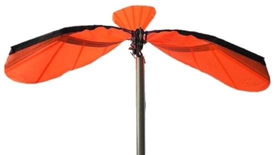
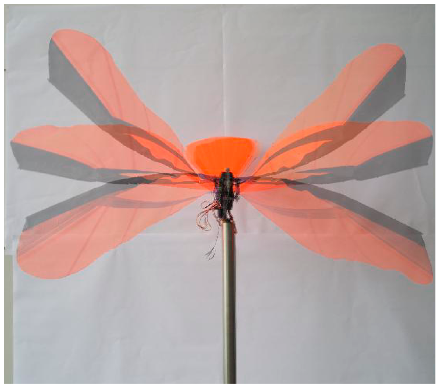
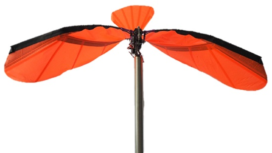
The ornithopter studied in this experiment (see
Figure 1) is a commercially available ornithopter kit from Carbonsail with a 1.3 m wingspan at the leading edge, remote-controlled by rib-stop fabric [
17].
Table 1 shows the mean chord length and aspect ratio of each wing, the mass of the ornithopter, the flight speed, the range of the wingbeat frequency and the Reynolds number. The kinematic viscosity of the air was used at 1 atm at 20 °C: 1.5 × 10
−5. The maximum tip speed was linearly scaled by comparing the ratio between the tip speed and flapping frequency and scaling the values for maximum and minimum wing frequency at 4.5 and 3.5 Hz, respectively (actual values can be confirm using OptiTrack). At 3.5 Hz the wing tip speed is estimated to be 5.8 m/s and at 4.5 Hz it is estimated to be 7.5 m/s.
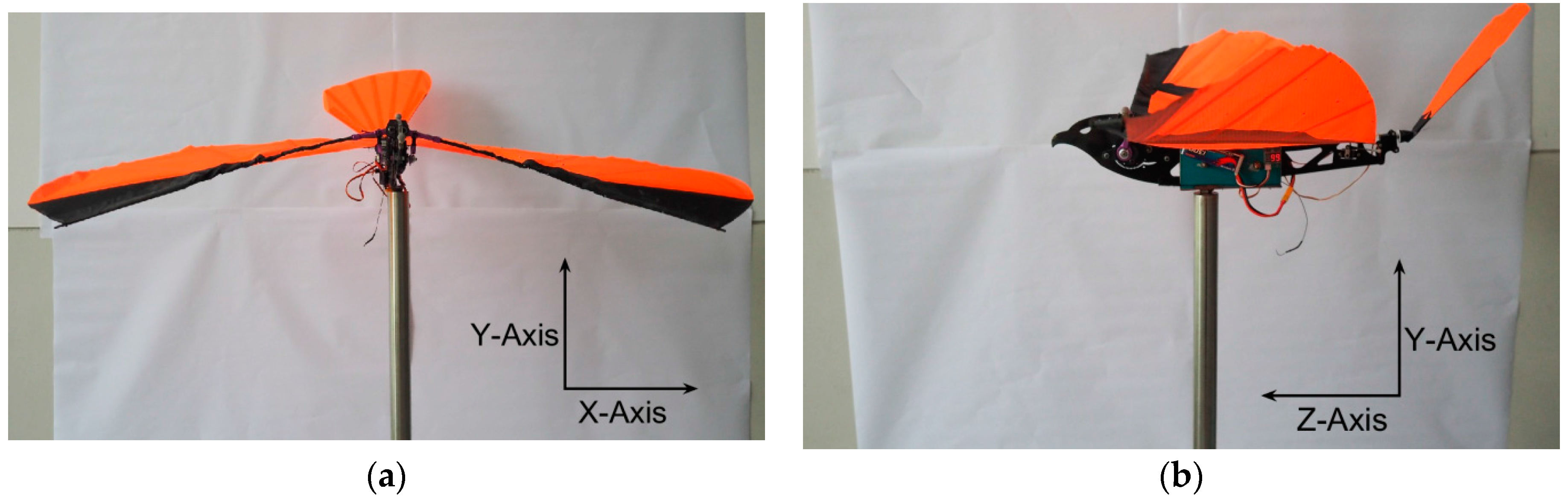
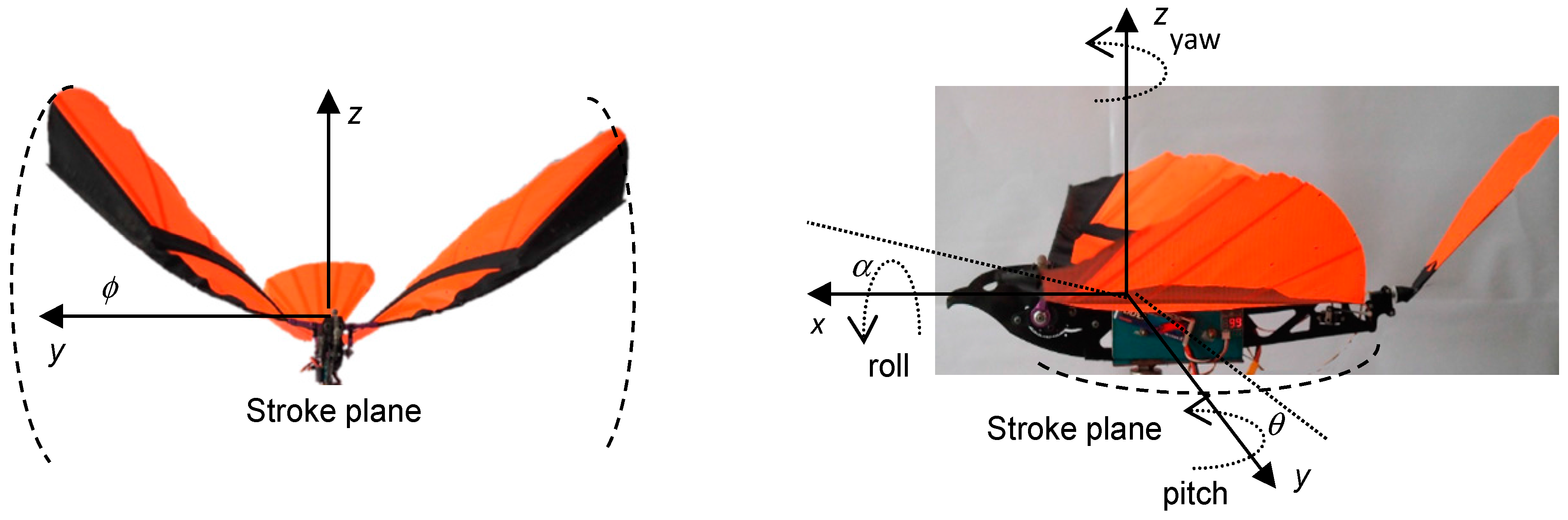
Figure 1 illustrates the axes’ orientation, with respect to the ornithopter, which will be used when describing the kinematic results in the subsequent subsections. A right-handed coordinate system, with its origin at the pivot point was defined as: positive
x from the body midline towards the tip of the left wing, positive
Y in the vertical upward direction and positive
Z from the wing trailing edge to the leading edge direction.
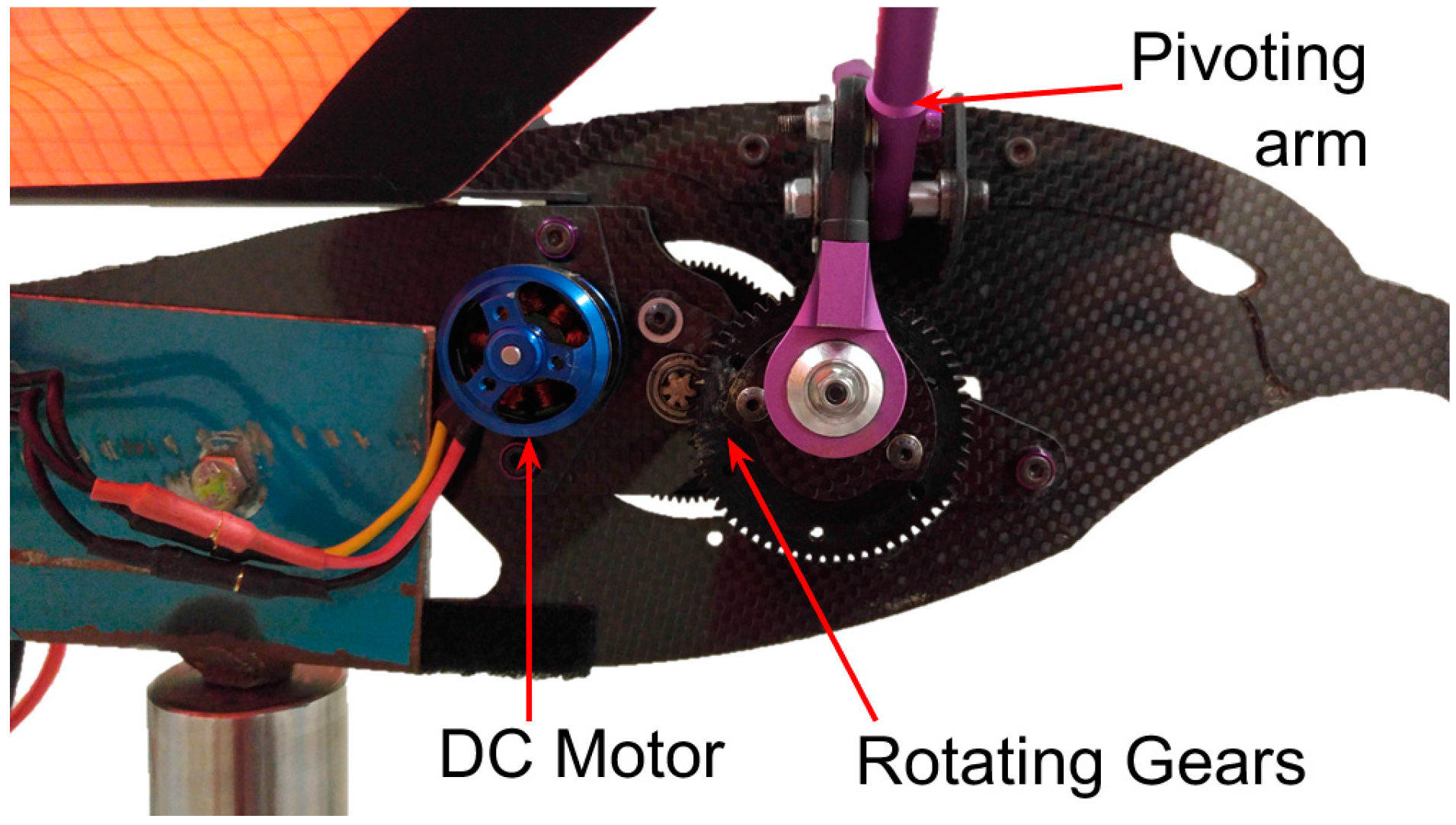
The flapping mechanism used on the ornithopter is of a traverse shaft design (see
Figure 2). While the heaviest and most complicated design for flapping mechanisms available, it allows for the most symmetrical flap. The plane of rotation for the rotating gears and the flapping wings are orthogonal; thus, the connector rod has to be able to rotate. A brushless DC motor was used as the actuator to drive the wing flapping mechanism.
3. Experiment Setup and Procedure
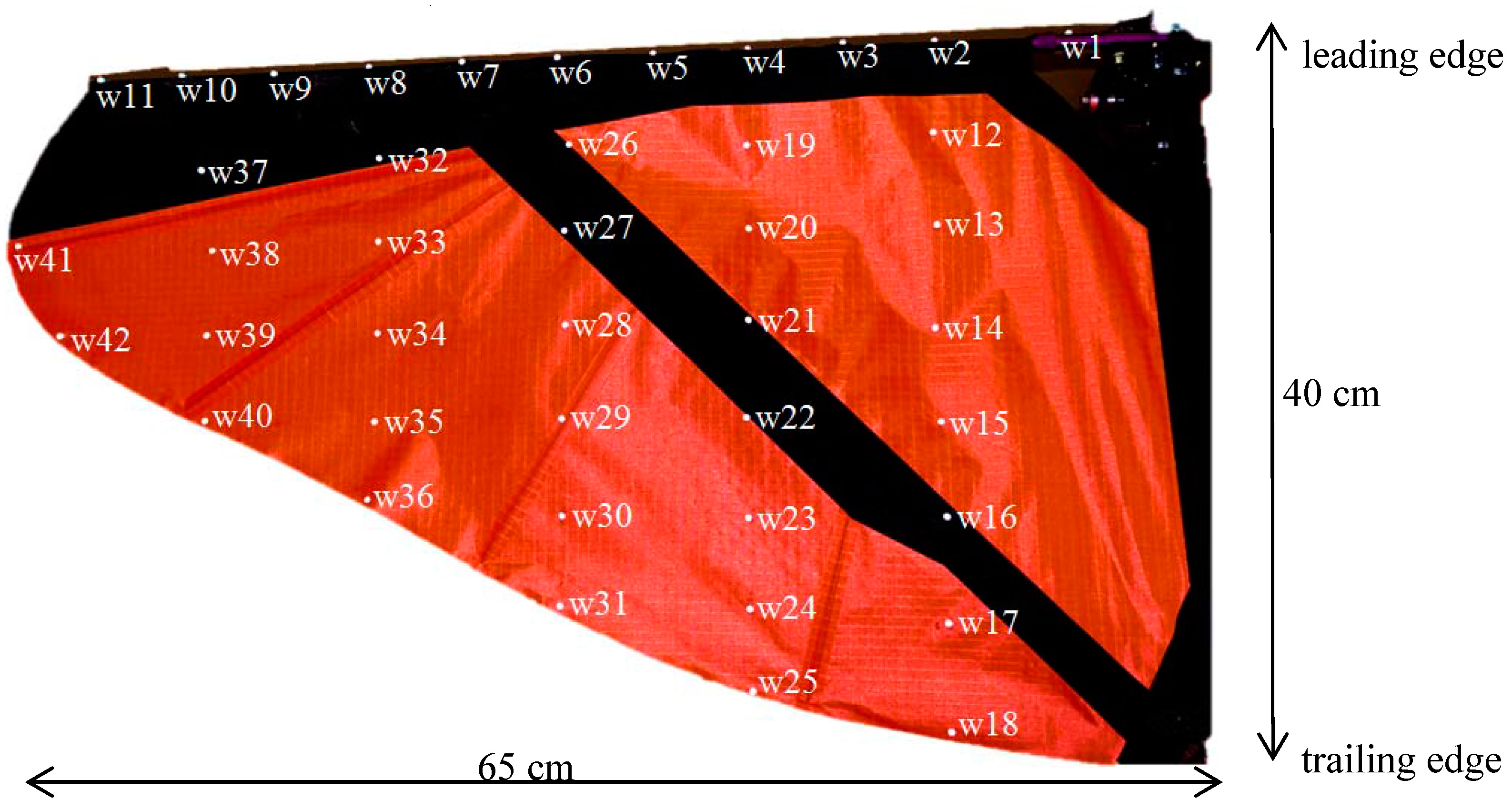
To prepare for the experiments, 42 retro-reflective hemispherical markers of 3 mm diameter were fitted onto the left wing of the ornithopter. The wing was split up into six sections: the leading edge and five “blade elements” along the wing membrane. Markers were placed at a 5 cm interval along both the leading edge spar and each “blade elements”. Each “blade elements” were spaced at 10 cm intervals. Lastly, two markers were placed at the wing tip along the membrane. The markers were labelled from w1 to w42 as shown in
Figure 3.
Blade elements are defined as follows: blade element 1 is made up of markers w12 to w18, blade element 2 is made up of markers w19 to w25, blade element 3 is made up of markers w26 to w31, blade element 4 is made up of markers w32 to w36 and blade element 5 is made up of markers w37 to w40. Lastly, the leading edge is defined by markers w1 to w11.
The markers in the case of this experiment are hemispherical and coated with a retroreflective material to reflect light that is generated near the camera lens. To enhance contrast, each camera is equipped with infrared light-emitting diodes and an infrared pass filter that is placed over the camera lens. Motion capture is ideal for capturing the dynamic behaviour of the wing during flight due to its minimal interference with the wing’s motion. Twenty cameras, each capable of recording position data with a precision of +/− 0.1 mm at rates of 360 frames per second, are included in this OptiTrack setup with the capacity of tracking an 8-by-8-meter capture volume. Data captured from the cameras is sent to the optical motion capture software Motive-Tracker [
18] where the markers positions are triangulated and the motion is reproduced in a six-degree freedom model.
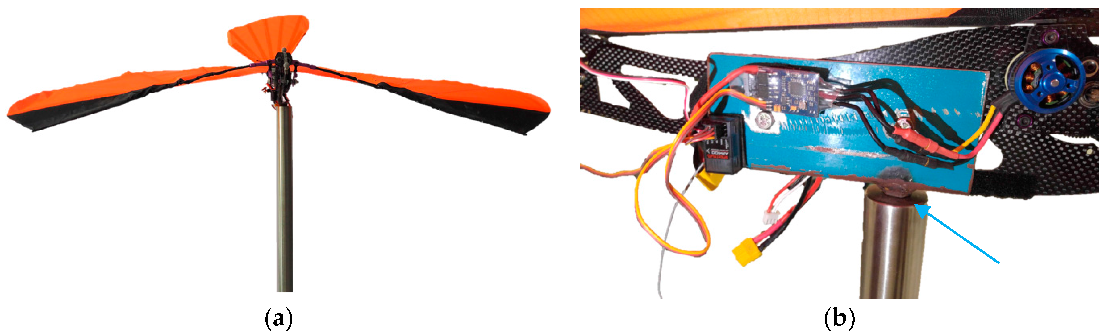
Due to asymmetric plunging of the wing below the ornithopter horizontal axis, a custom test stand (see
Figure 4a) and clamp (see
Figure 4b) had to be fabricated to accommodate the slim profile of the ornithopter body, while sufficiently alleviating the ornithopter off the ground without impeding wing movement.
Regarding the tracers, according to Harmon et al. [
19], the total weight of the markers would have to exceed five grams for the mass of markers to detrimentally affect the wing dynamics. In our experiments, the total weight of the markers fixed onto the ornithopters adds up to 0.42 grams; therefore, we considered any dynamic effects are negligible.
5. Force Measurement
Together with the kinematic data as presented in the previous section, we took measurement of the lift force generated by the flapping motion of this ornithopter. The setup was similar to the one shown in
Figure 4a,b. In addition, we installed the force transducer (load cell) at the connecting point between the ornithopter and the support stands, as shown in
Figure 4b.
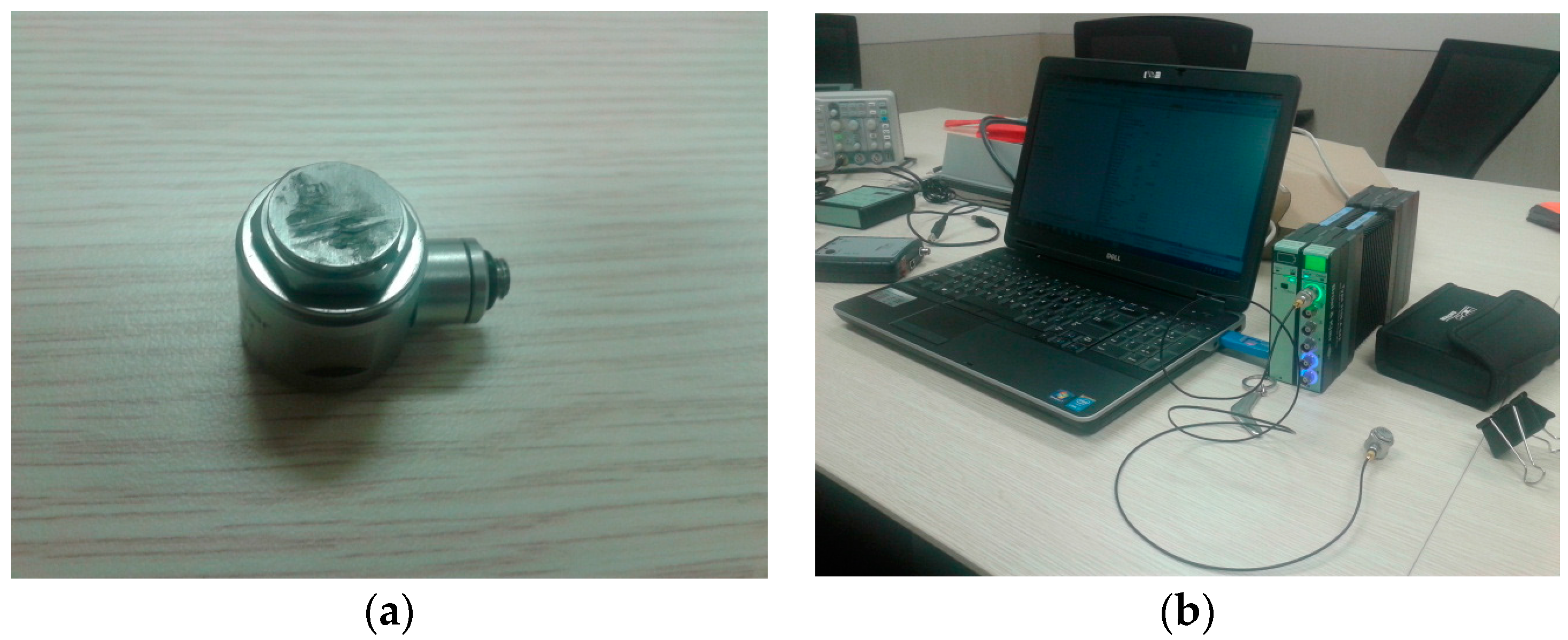
The load cell used was Brüel & Kjær-DeltaTron
® Force Transducers Types 8230, capable of measuring between 0 and 20 N with 0.01 N sensitivity and 0.001 error margin [
20], as shown in
Figure 19. The measured load data was transmitted to the recording PC [
20] via the data acquisition system with the extended Kalman filtering system; hence, the recorded load data was already filtered out of the environment and white noise signals.
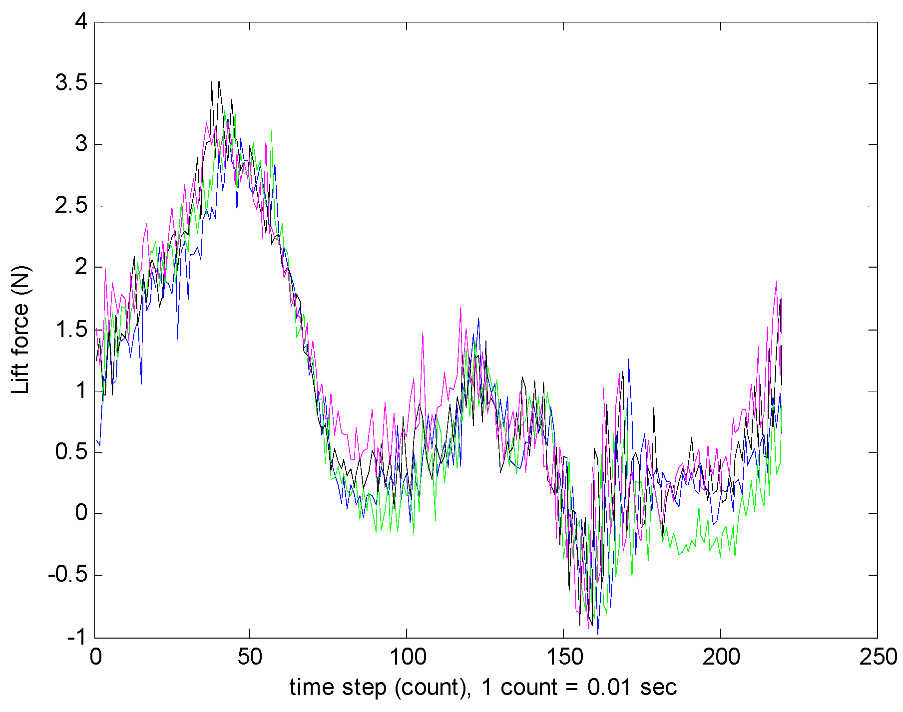
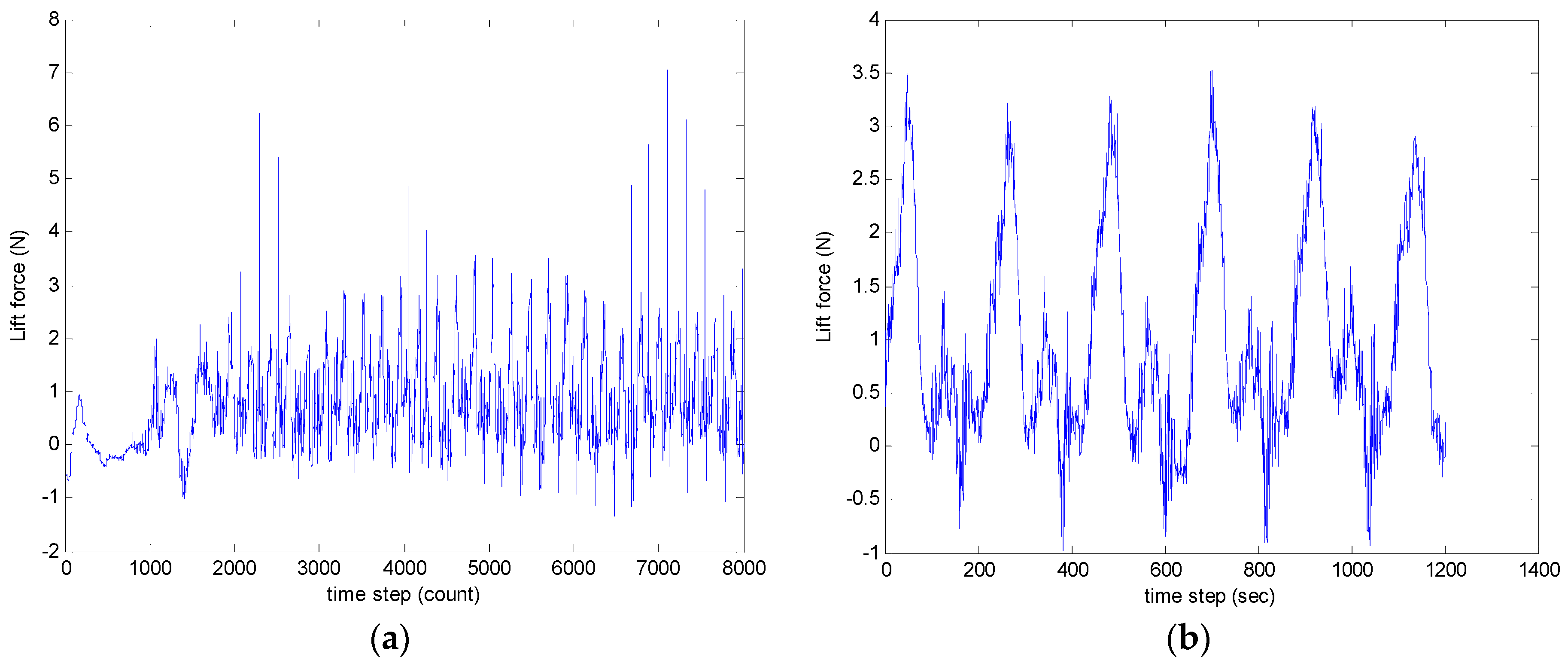
The ornithopter was set to flap at the same condition, i.e., when the wing oscillated at 3.93 Hz. This corresponded to 50% throttle power. The wing was first set to flapping motion for 10 cycles to stabilize the flapping motion, and to let the following flapping motion be steady. Then, we took a recording of the lift force generated for the six subsequent cycles as shown in
Figure 20.
From
Figure 20, we noticed that after the 10 initial flapping cycles, the ornithopter could flap more steadily.
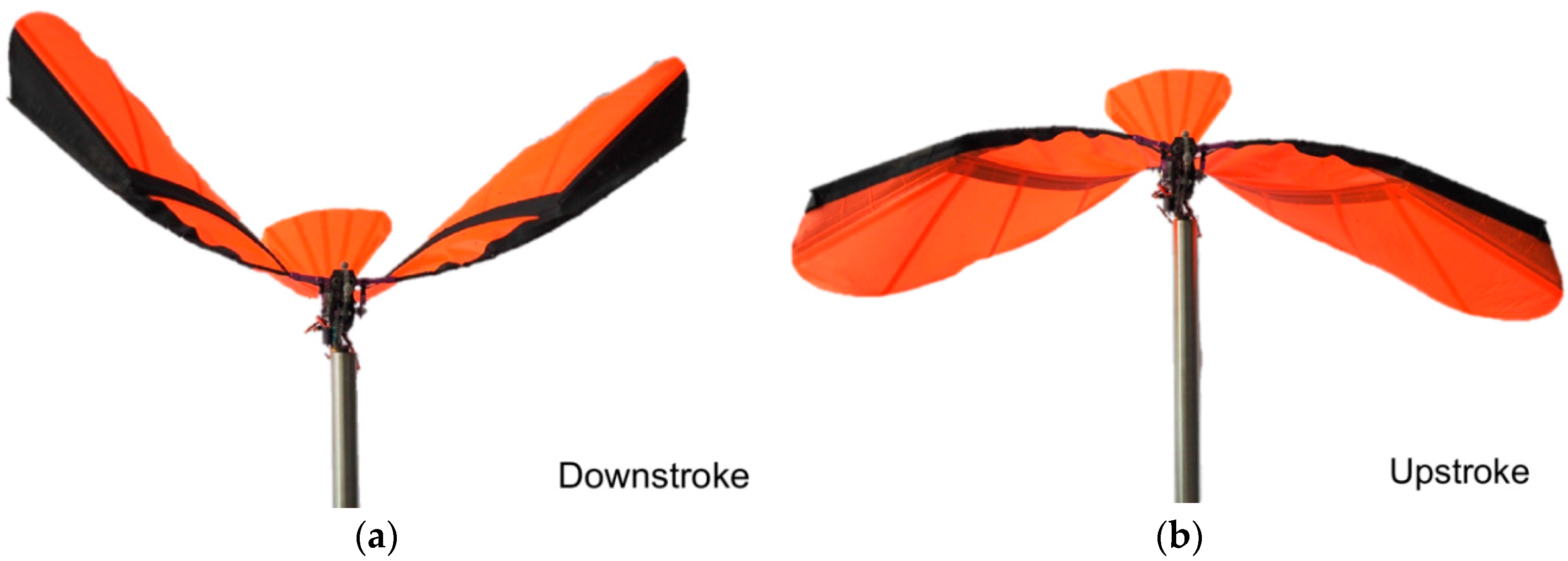
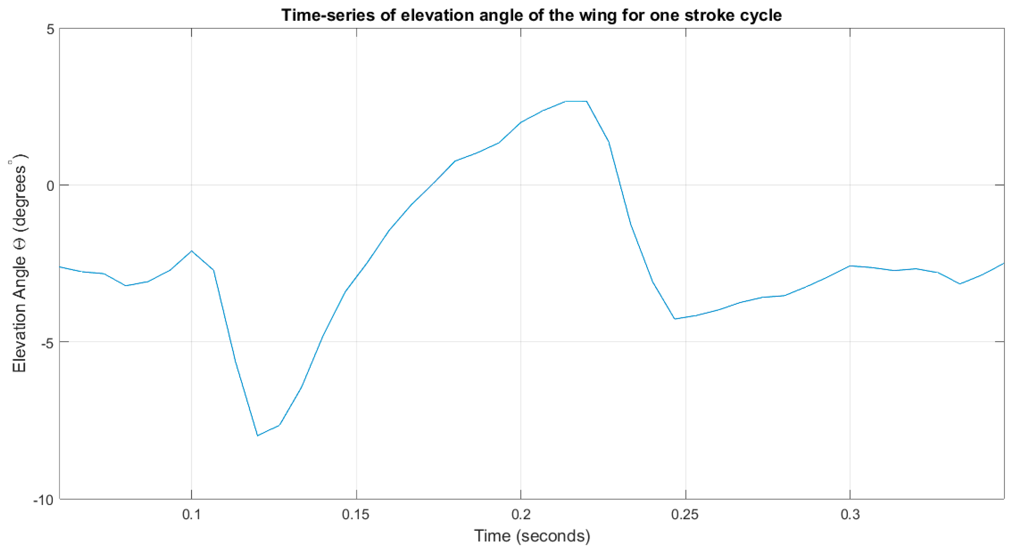
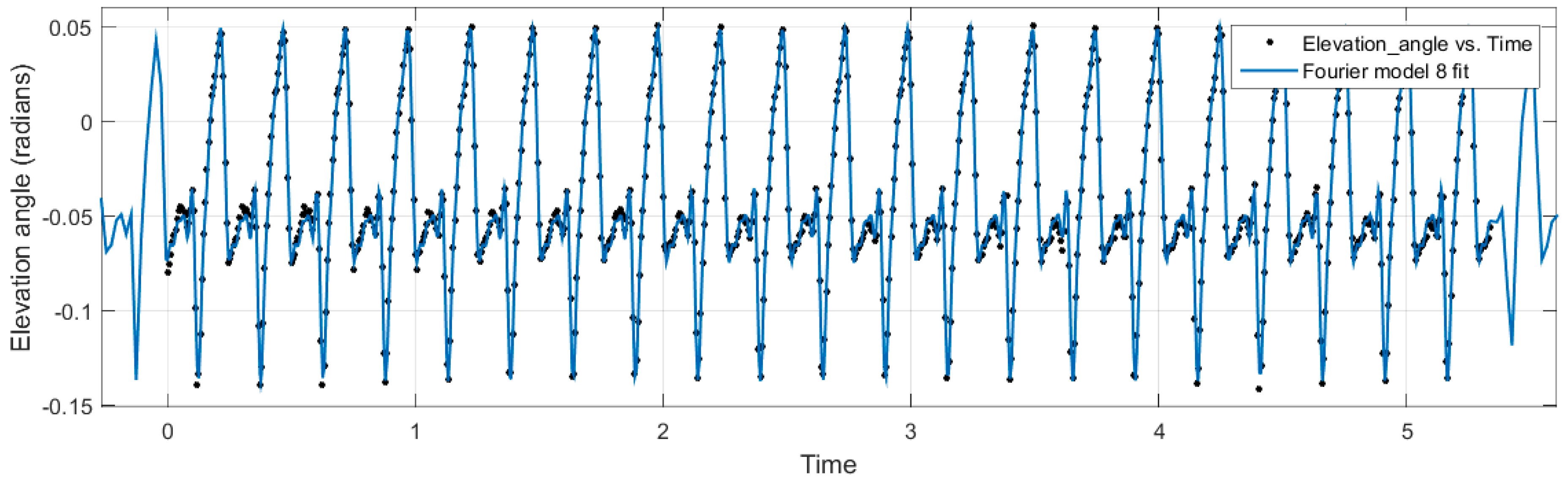
Figure 21 showed the lift force generated in one cycle, from downstroke (gaining lift) to upstroke (loosing lift). The lift force generation graph resembles the elevation angle plot as presented in
Figure 16. We can conclude that it is the elevation angle of the flapping wing that is the main contributor to the amount of the lift, whereas the feathering and flapping angles have a lesser effect.
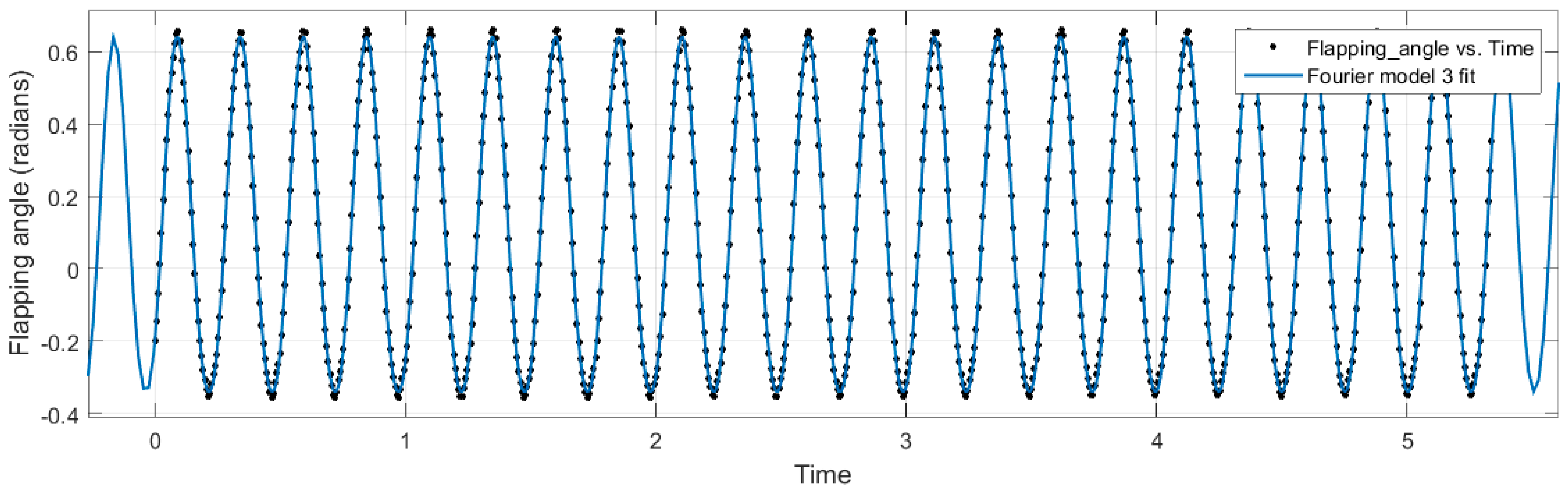
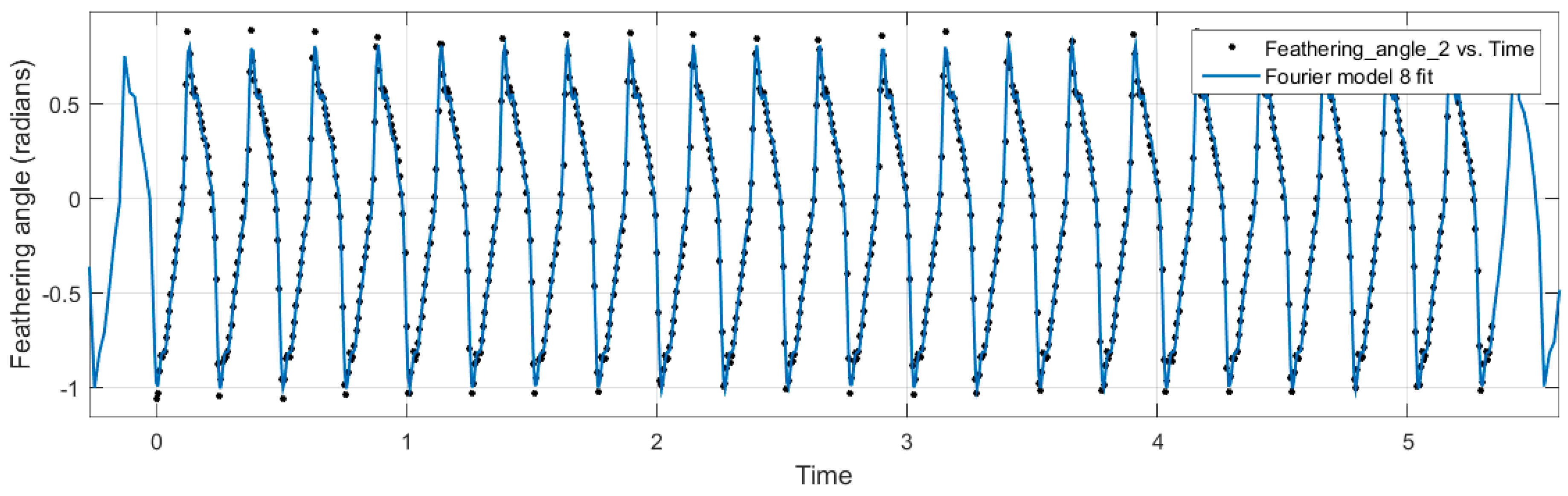
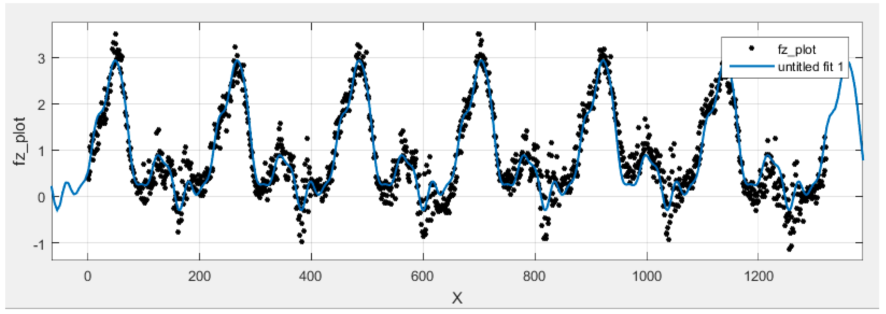
Figure 22 shows the curve-fitting solution by the MATLAB curve-fitting tool. As specified by the Fourier series for lift force, the minimum number of the coefficient selected to fit the curve is eight terms. The coefficients are as listed in
Table 5. The angles are in radians.
6. Discussion
This paper presents the kinematic analysis of an ornithopter wing through motion tracking experiments. The motivation for this research was to isolate the wing geometry and kinematics with time in three-dimensional space and analyse the physical deformation of the wing for a complete stroke cycle. Motivated by the success and quality of the kinematic data, the various position angles were studied and a mathematical equivalent was derived from the empirical data. It was noted during the analysis, however, that for a full and proper curve fit to be made for the data points collected, up to eight Fourier coefficients would have been needed. The values of the fourth to eighth coefficients were so small compared to the first three terms that they were neglected and only the first three terms were considered as the dominating terms.
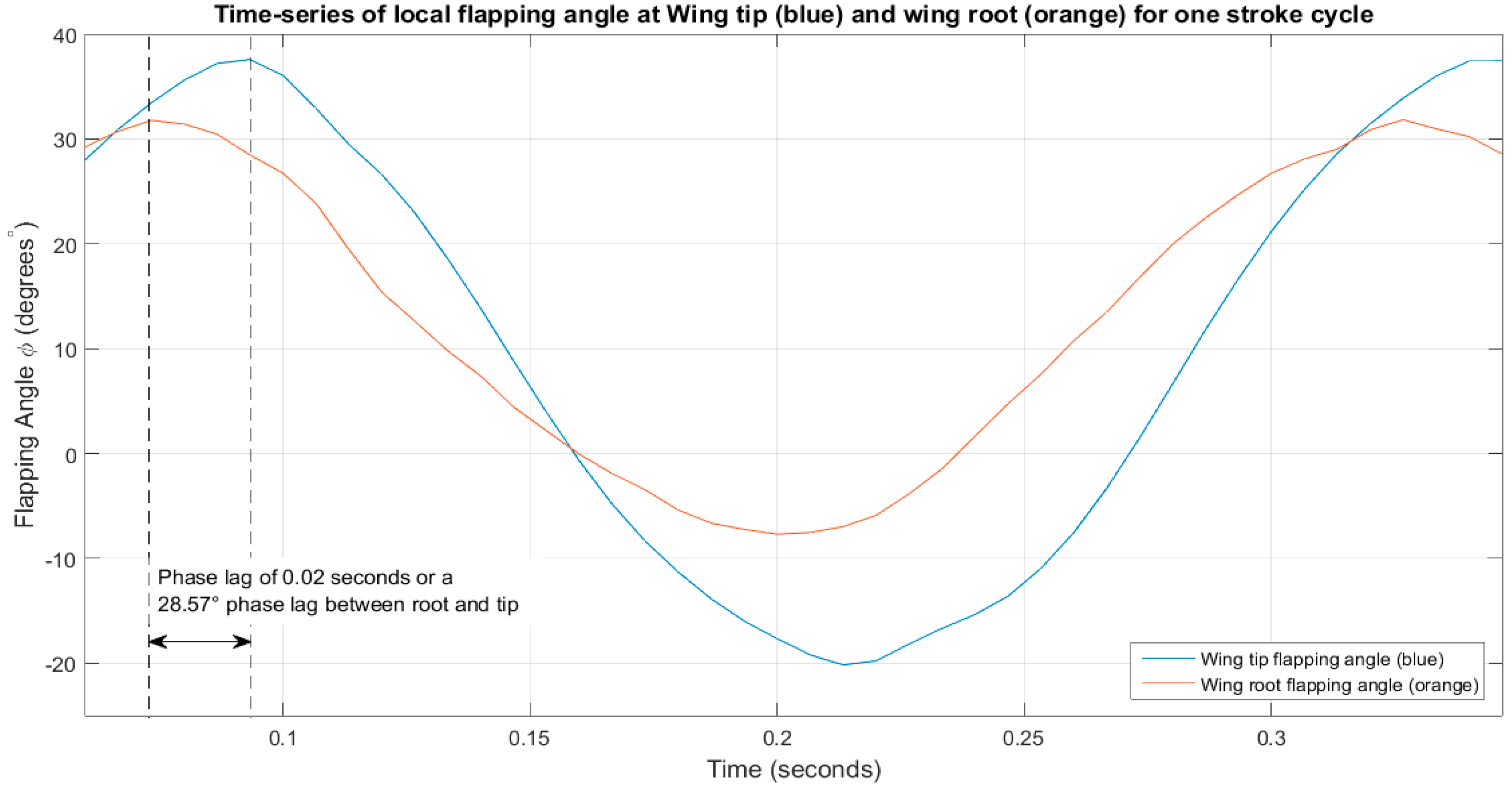
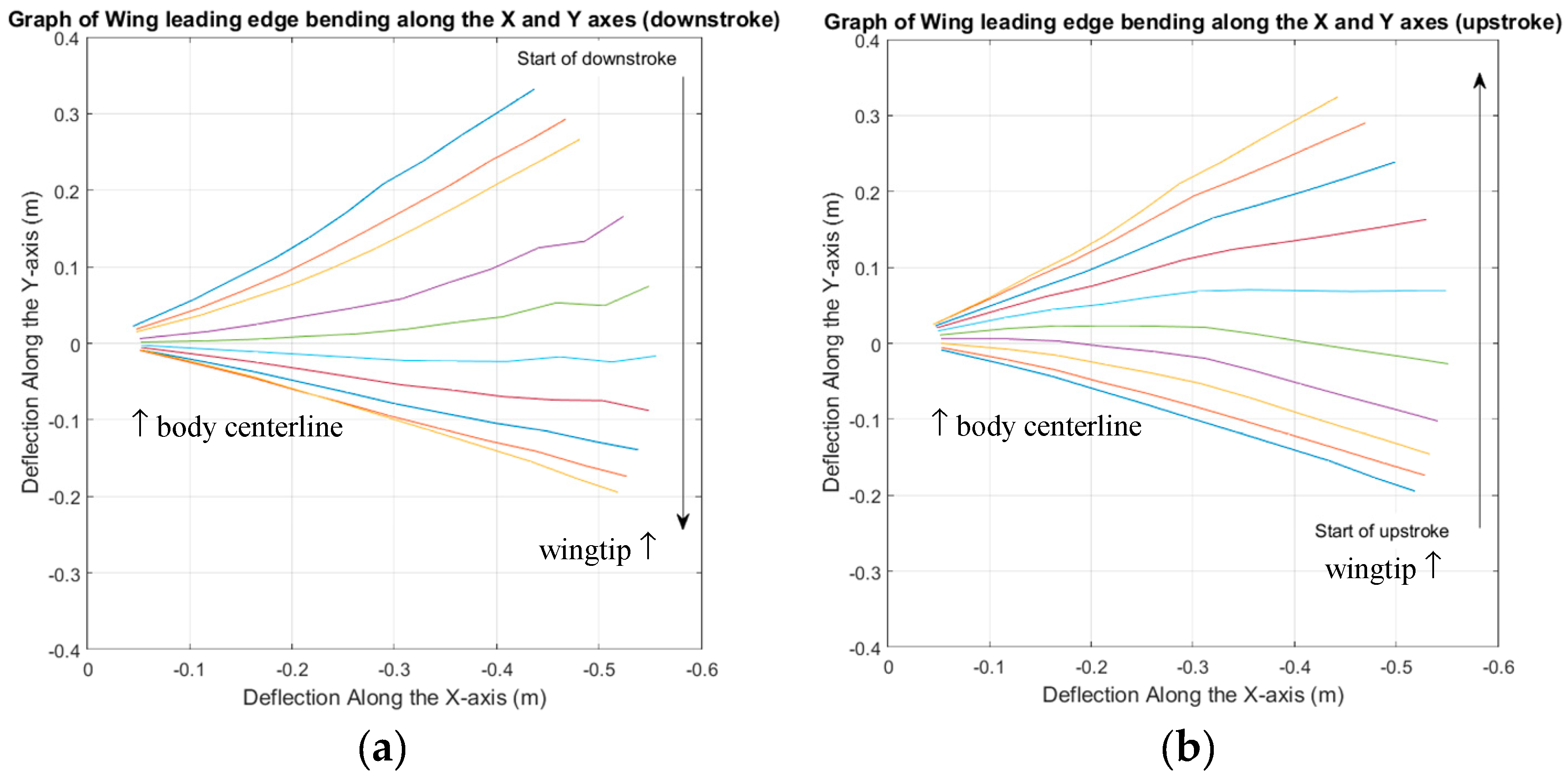
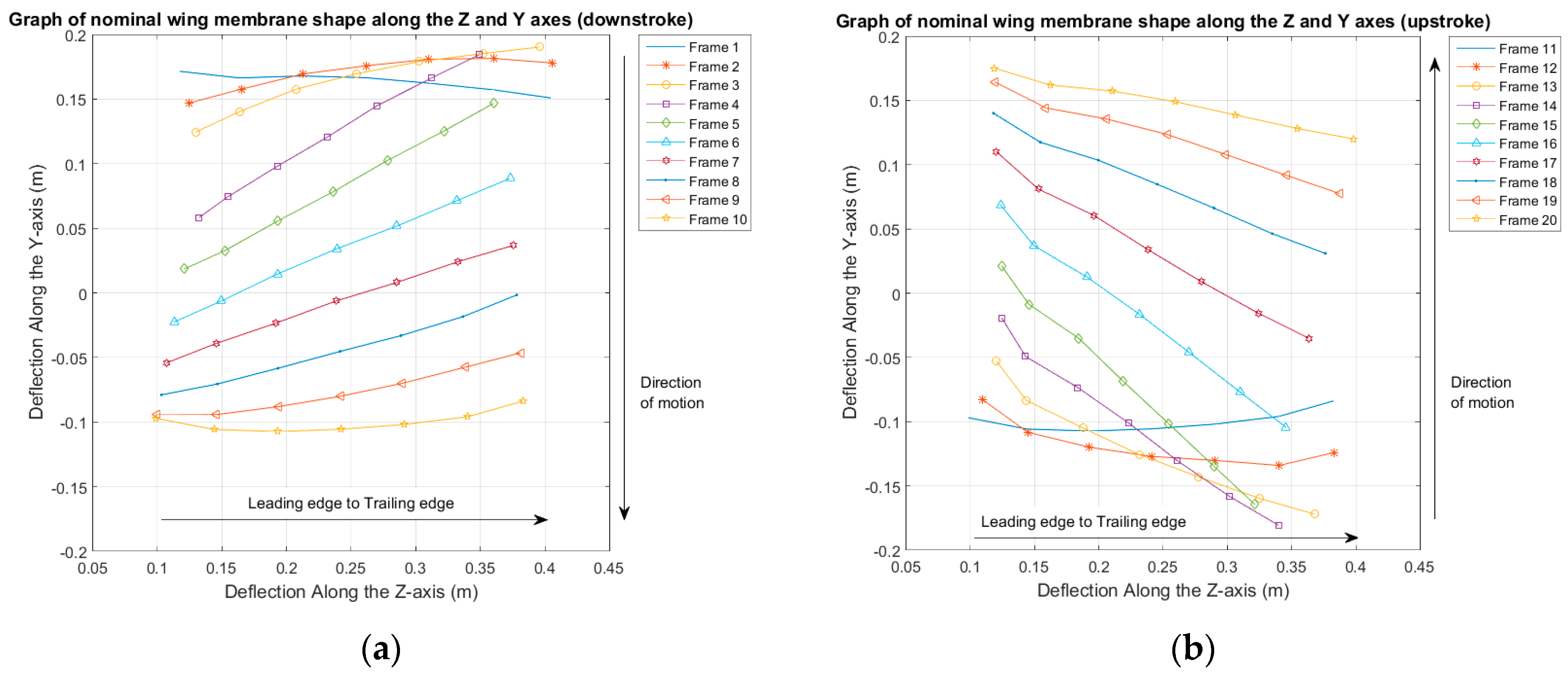
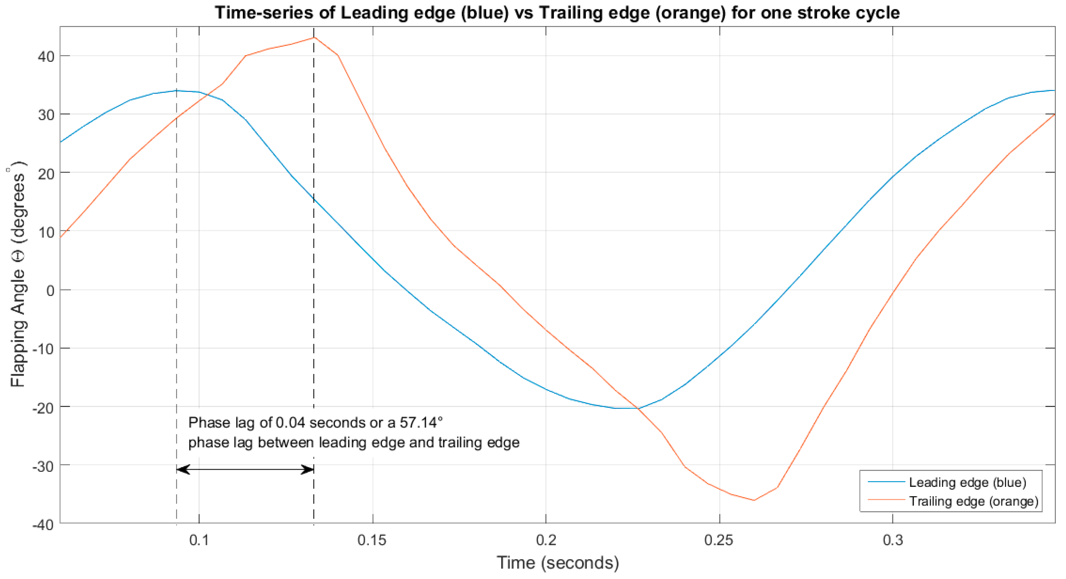
Primary kinematic analysis showed that the ornithopter utilized a vertical stroke plane for flight but experienced significant bending spanwise along the leading edge as well as chordwise pitching along the wing span, similar to what was studied in “Avian flight” and “Animal locomotion” [
8,
18]. This resulted in the lead-lag nature of the wing with the tip lagging behind the root by 28.57° and the trailing edge lagging behind the leading edge by 57.14°. As such, this resulted in the constant undulating surface of the wing.
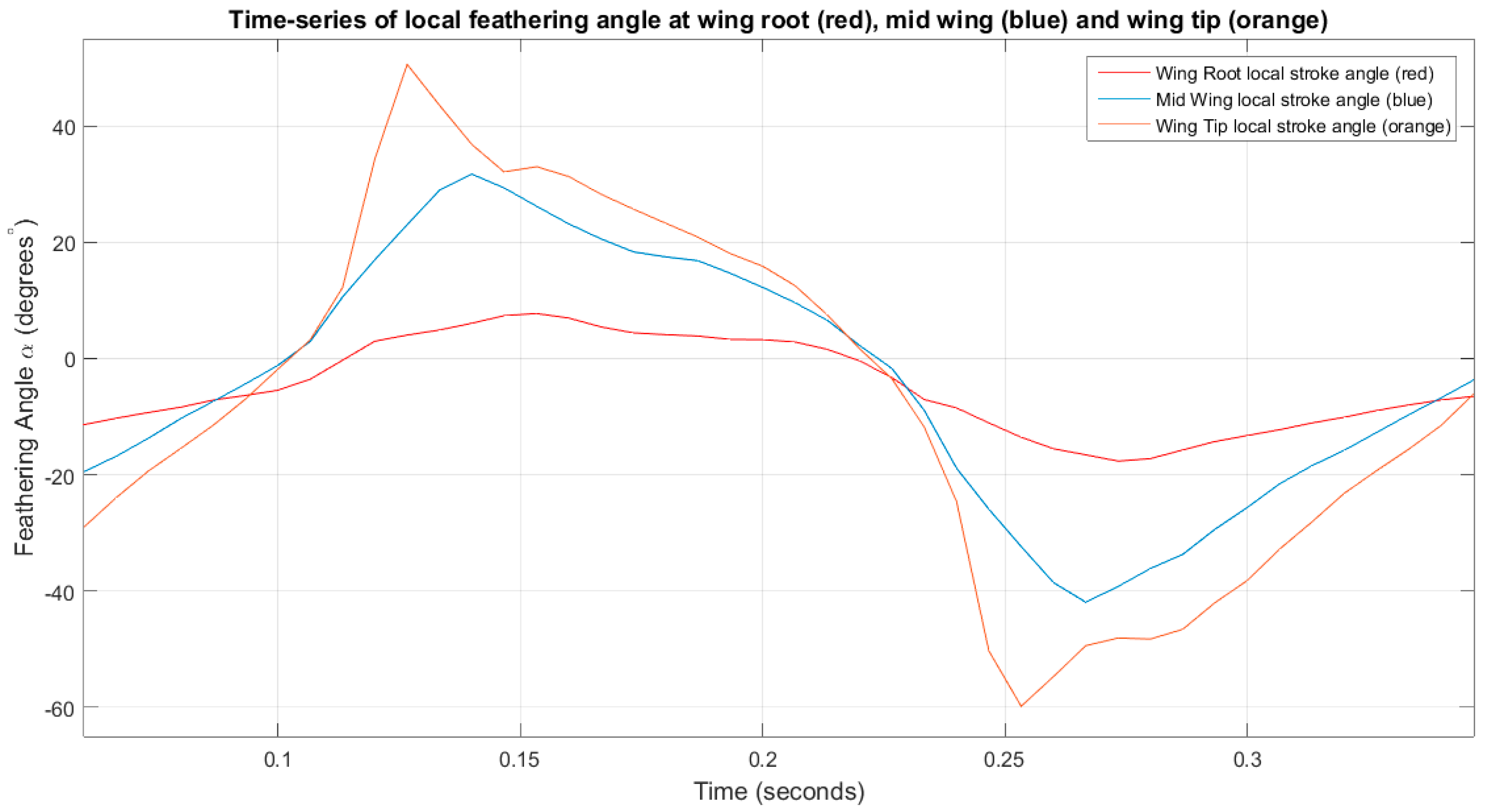
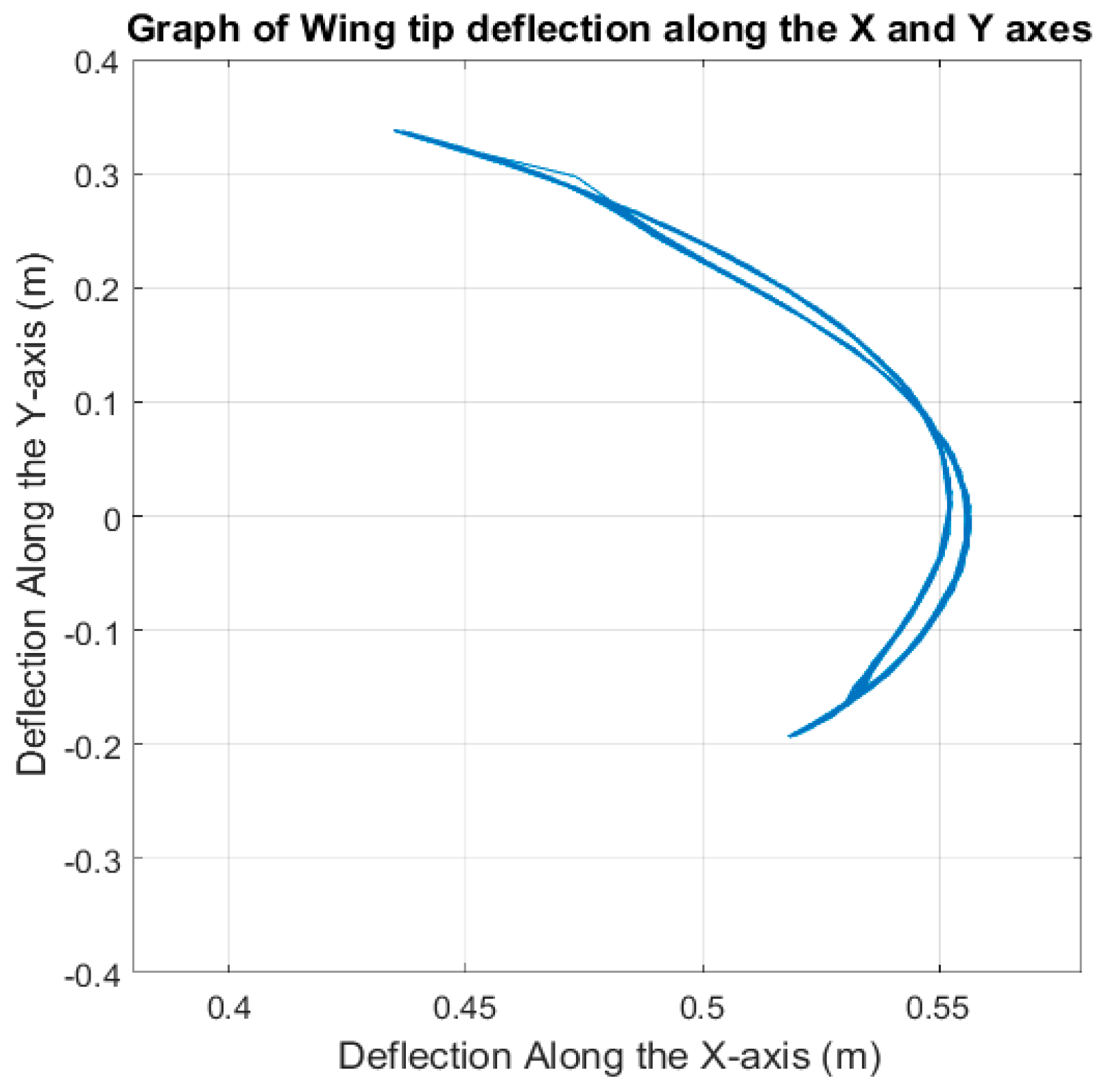
Analysis of the wing tip showed that the wing closely mimics the flight motions of birds with the coupled vertical and horizontal motions replicating the typical figure-eight-shaped kinematics of a bird’s wing. The wing was shown to be highly flexible, capable of achieving high twist angles of +/−50°. The ornithopter also has a higher upper-range flapping angle of +30°; however, the flexing of the wing balances the lower range flapping angle to −20°.
The force reading shows the lift generated follows the elevation of the main flapping wing.
As a next step, we plan to repeat the experiments at various frequencies with the addition of a load test cell to measure the associated lift force and to complete a motion tracking experiment in hover condition at various angles of attack to investigate the effects of gravity on wing bending.


