Article

Experimental Study of Aerodynamic and Bird Exclusion Characteristics of a Branched Turboprop Inlet Under Ground Suction Conditions

College of Energy and Power Engineering, Nanjing University of Aeronautics and Astronautics, Nanjing 210016, China
*
Author to whom correspondence should be addressed.
Aerospace 2025, 12(7), 640; https://doi.org/10.3390/aerospace12070640 (registering DOI)
Submission received: 27 May 2025 / Revised: 2 July 2025 / Accepted: 18 July 2025 / Published: 19 July 2025
(This article belongs to the Special Issue Environmental Influences on Aircraft Aerodynamics)

Abstract

A turboprop aircraft is exposed to the risk of bird strikes during flight, which may have a serious impact on flight safety once the bird is sucked into the engine. In this study, the aerodynamic and bird exclusion characteristics of a branched turboprop inlet were tested on a branched turboprop inlet–bird striking experiment system under ground suction conditions. The ingestion processes of the bird were captured by a high-speed camera system. The static pressure at the inner wall of the inlet during the ingestion process was measured. The results indicate that when a low-speed bird at a large incident angle impacts on the wall of the inlet near the lower lip under ground suction conditions, the bird is easily sucked into the core duct. Conversely, it is more likely to be excluded by the bypass duct. Moreover, when the bird moves into the inlet, the static pressure on the wall of the area where it passes through increases significantly.

1. Introduction

In recent years, the growth in demand for civil aviation transportation has led to the rapid development of transport aircraft, especially turboprop aircraft. A turboprop aircraft has the advantages of higher fuel efficiency and greater takeoff thrust [1,2,3] so that it is widely utilized in short-haul commuter, military transport, and patrol aircraft [4,5]. However, turboprop aircraft may encounter harsh environments during flight in which a variety of foreign objects (bird [6,7], hailstone [8], ice slab [8,9], raindrop [10], and sand [11]) can be sucked into the engine. Foreign objects may cause serious damage to the engine. For example, sand can erode the blades of the propeller and internal structure of the engine, causing a significant reduction in their performance [12,13].
Among these various foreign objects, the size of a bird is the largest, so that it produces more serious damage to the engine. Once this occurs, it often results in a catastrophic accident. First of all, the mixing of the airflow from the inlet and the bird will lead to a decrease in the quality of the flow field, so that the aerodynamic performance parameters of the inlet may be significantly reduced [6,14]. Furthermore, the birds may damage the surface of the propeller and the inlet, so that significant degradation of the structural safety of the aircraft and the aerodynamic performance of the propellers may occur. In addition, if birds are not excluded from the engine, they will cause more serious damage to the internal structure of the engine [7,15,16]. Therefore, to prevent foreign objects from entering the engine, a kind of branched turboprop inlet is being developed, which is composed of a core duct and a bypass duct [6,17]. The core duct is located at the upper part of the inlet to connect to the compressor; the bypass duct is located at the lower part of the inlet to connect to the atmosphere. Foreign objects can be effectively excluded by the bypass duct through its own inertial force, leaving clean airflow to be conveyed to the core duct.
At present, there has been significant progress in the studies of the aerodynamic characteristics of the branched turboprop engine inlet [6,17,18,19,20,21], and numerical investigation of foreign object exclusion (FOE) within the inlet has developed significantly. However, the experimental investigation of FOE within the inlet remains in its early stages. The research on foreign objects mainly focuses on the deformation of the aircraft structure during the impact of foreign objects on the aircraft [22,23,24,25,26]. As for the study of the trajectory of the foreign object, Michael Papadakis et al. developed a four-degree-of-freedom (4-DOF) computational method to analyze the shedding process of ice slabs with different shapes [27]. Later, they further developed a six-degree-of-freedom (6-DOF) trajectory calculation method to simulate the shedding process of ice slabs from the wing and fuselage of a jet aircraft [28], and conducted a wind tunnel test to measure the trajectory of the ice slab shedding in the airflow [29]. In addition, numerical research on the motion characteristics of foreign objects within the inlet has advanced significantly. Mi et al. have conducted a number of studies on the exclusion characteristics for the branched turboprop engine inlet [9,30,31]. At first, they evaluated the performance of a certain type of turboprop engine inlet with a bypass duct in 2019. A CFD combined with a six-degree-of-freedom simulation method is proposed to comprehensively analyze the impact, exclusion, and interference generated by rigid foreign objects in the inlet [30]. However, this simulation model is based on a fully elastic collision, which is too idealized. In actual flight, the foreign objects will be coupled with the internal flow field after entering the inlet, and the trajectory of the foreign objects will be more complicated. Later, they simulated the process of hailstone and ice slab ingestion into the engine using LSDYNA R10.1.0 in 2020. It was found that ice slabs initially located at the lower lip were susceptible to being sucked into the core duct, thus threatening the engine [31]. What is more, they established a numerical simulation method for the motion of two kinds of fragile foreign objects (ice slab and hailstone) in the turboprop inlet with a bypass duct by combining the unsteady CFD technique, 6-DOF, and CSD impact theory. The exclusion characteristics of the ice-type foreign objects and their impacts on the aerodynamic performances of the inlet were evaluated in detail [9]. Zheng et al. also conducted a lot of studies on the bird exclusion characteristics in a branched turboprop engine inlet [6,14]; they introduced a numerical simulation method coupling the self-developed collision–rebound model, overset mesh, and 6-DOF to calculate the bird exclusion characteristics of a turboprop inlet under propeller interference at a large angle of attack. And through the parametric design method, the exclusion performance of the inlet was optimized [6].
In summary, there are many numerical studies on the aerodynamic characteristics and FOE of the branched turboprop inlet at the moment, whereas experimental studies of FOE in the inlet have rarely been reported. As a result, in this paper, an experimental study of the aerodynamic and bird exclusion characteristics of a branched turboprop inlet with a bypass duct under ground suction conditions based on a branched turboprop inlet–bird striking experiment system is conducted. The bird exclusion characteristics of the inlet and the aerodynamic effects of bird striking on the inlet are discussed. Section 2 presents a detailed description of the experimental setup of the branched turboprop inlet–bird striking experiment. Section 3 describes the terminological definitions in this paper. Section 4 presents a discussion of the experimental results. Section 5 draws a conclusion of the present study.

2. Experimental Setup
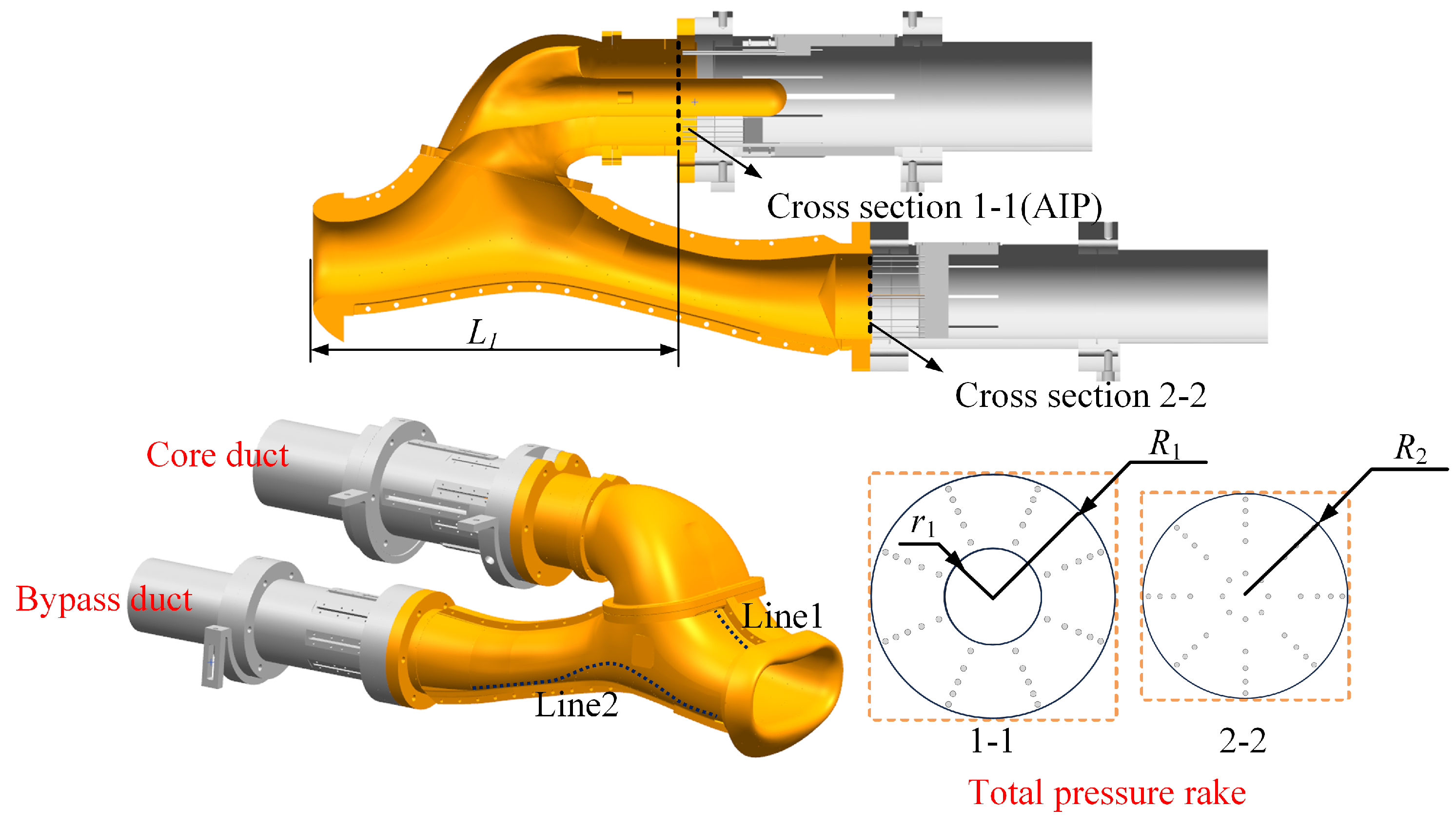
2.1. Test Model

The test model of a branched turboprop engine inlet is composed of a core duct and a bypass duct. The power extraction shaft passes through the core duct, forming a circular cross-section of the core duct. The total pressure rake for the core duct is installed at the aerodynamic interface plane (AIP, located at the outlet of the inlet and the entrance of the compressor) between the inlet and the engine, and the total pressure rake for the bypass duct is at the outlet of the bypass duct. Additionally, static pressure measurement points are arranged on the outer surface of the model to collect the static pressure of the wall. Since one side is used for capturing the motion trajectory of the bird dummy, 26 static pressure measurement points are distributed along the other side, with 6 points on Line1 and 20 points on Line2. Line1 is located on the upper wall of the inlet entrance, and Line2 is positioned on the side of the bypass duct. The test model is shown in Figure 1, and the geometric parameters of the inlet are tabulated in Table 1.

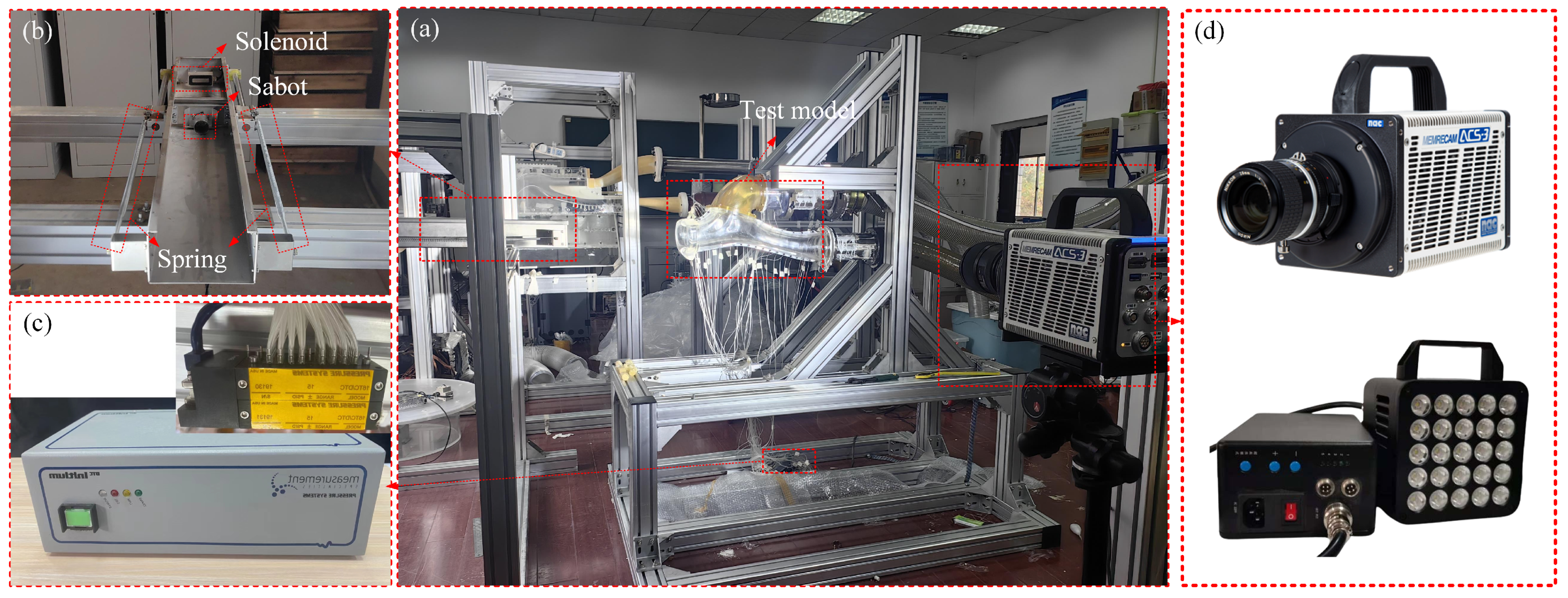
2.2. Experimental System

A branched turboprop inlet–bird striking experiment system (Figure 2) is designed to conduct the aerodynamic and exclusion experiment of the branched turboprop inlet under ground suction conditions. The experimental system includes a low-pressure storage tank suction experiment platform, a transparent turboprop inlet model, two total pressure rakes connecting the two ducts, a launcher (Figure 2b), a pressure measurement device (Figure 2c), and a high-speed camera system (Figure 2d).
The launcher consists of a projection plate with a sabot, two springs, a solenoid, a slide, and a triggering device. The solenoid is energized so that the projection plate is absorbed by the solenoid. When the experiment is ready, the solenoid is de-energized by controlling the triggering device, and the bird is launched using the elasticity of the spring at an initial velocity of about 1–10 m/s.
The pressure measurement device is an electronically scanned pressure transducer system (ESP-64HD) produced by the PSI company in the United States, with a measurement accuracy of 0.05% of the full scale. Because the measurement range of the ESP modules is 15 psi (103,421 pa), the maximum error of the pressure measurement device is approximately ±52 pa. The high-speed camera system consists of a high-speed camera and an LED light. The high-speed camera is a Memrecam ACS-3 high-speed camera produced by Nac Image Technology Inc. in Japan. It has a maximum of 1 megapixel. At this full frame resolution, the frame rate is up to 30,000 fps, and the maximum speed is up to 220,000 fps, with a maximum frame rate of 250,000 fps at 1280 × 896 resolution and 50,000 fps at 1280 × 448 resolution. The camera is placed on the side of the inlet and equipped with an LED light to enhance the shooting effect. The resolution of the high-speed camera in the experiment is adjusted to 1280 × 896, and the frequency is 10,000 fps.
During the aerodynamic experiment, the air source of the experiment is provided by the low-pressure storage tank suction experiment platform. After reaching the required pressure for the experiment by adjusting the valve, the wall pressure along the inlet and the outlet pressure are collected by the pressure measurement device.
During the exclusion experiment, the wall pressure along the inlet and the outlet pressure without the bird dummy are collected first. Subsequently, the bird dummy is launched by controlling the triggering device. At the same time, the wall pressure along the inlet and the outlet pressure during the motion of the bird are captured. In addition, a high-speed camera system is used to monitor the trajectory of the bird in the inlet. Notably, a filter is installed at the outlet to prevent birds from entering the suction duct, and the total pressure rakes are removed to protect the probe on the total pressure rakes in this process. The operation conditions required are adjusted by the position of the valve.

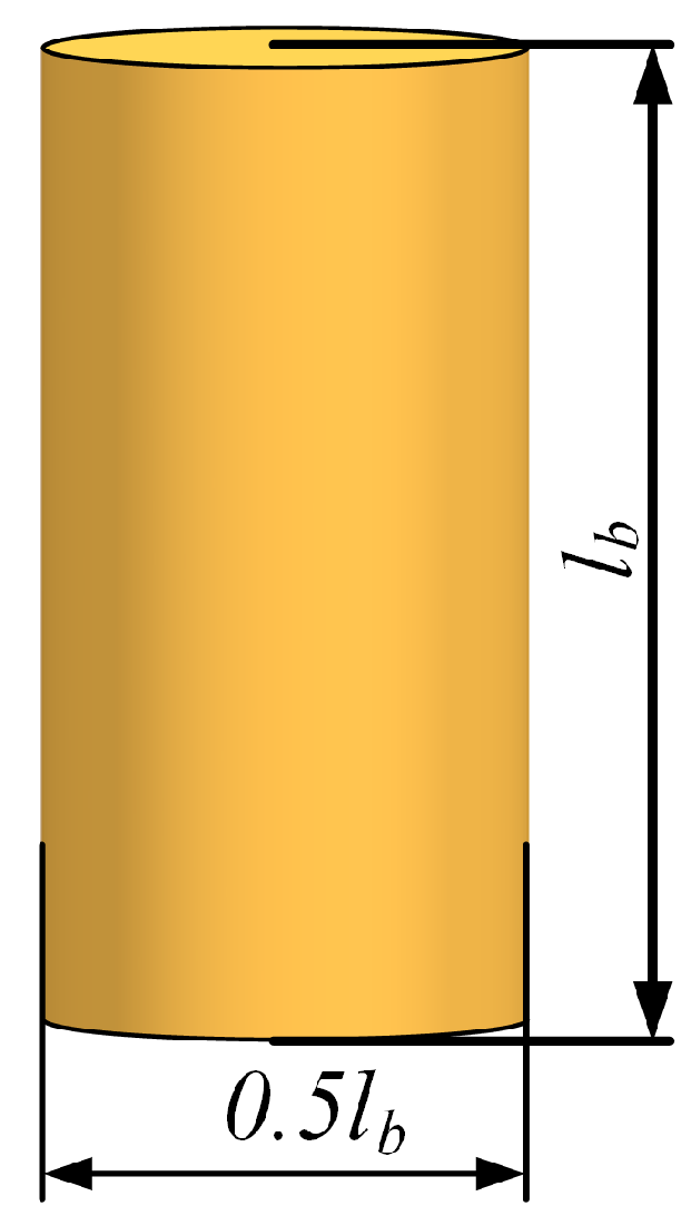
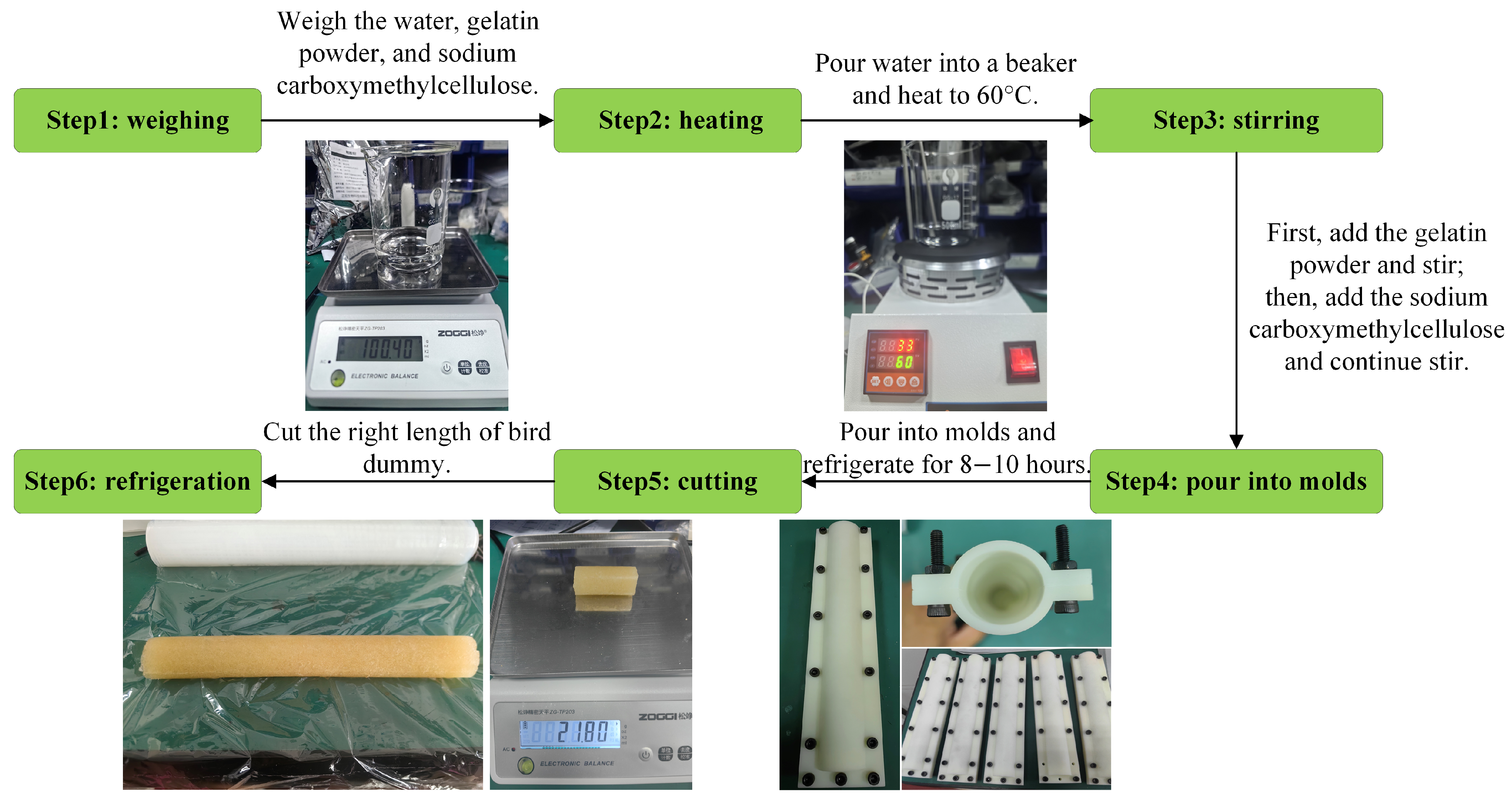
2.3. Bird Dummy Selection and Preparation

The bird dummy is modeled as a cylinder made of gelatin with an aspect ratio of 2:1 in this study to keep it consistent with previous studies [22,24,32,33], as shown in Figure 3. The geometry parameters of the bird dummy are shown in Table 2.
Based on the formulation of the bird dummy documented in the relevant literature [34], gelatin is utilized to prepare the bird dummy. The elasticity and hardness of the bird dummy are adjusted by modifying the ratios of the water, gelatin powder, and sodium carboxymethylcellulose during the preparation process. Since the bird dummy made from the literature [34] (10:1 ratio of water to gelatin) is too soft, a ratio of 5.5:1 water to gelatin and 4:1 gelatin to sodium carboxymethylcellulose is used to make the bird dummy in this paper. The density of the bird dummy is 950 kg/m3, and the process of preparation is shown in Figure 4. First, 110 g of water, 20 g of gelatin powder, and 5 g of sodium carboxymethylcellulose are weighed for each preparation. Subsequently, the water is heated to 60 °C, the gelatin powder is stirred until completely dissolved, and then the sodium carboxymethylcellulose is stirred until completely dissolved. Finally, the stirred gelatin liquid is poured into the mold. After 8–10 h of refrigeration, the mold is opened. The right length of the bird dummy is cut and wrapped with a plastic wrap for refrigeration. The prepared bird dummies have a mass range of 20–22 g, a length of 48 ± 2 mm, and a base diameter of 24 mm.

3. Terminological Definitions

Some basic concepts and terminologies need to be defined before the discussion of the results.
The total pressure recovery coefficient, σ , is defined as
σ = p AIP * / p 0 * .
where p AIP * is the average total pressure at the AIP, and p 0 * is the freestream total pressure.
The total pressure distortion index (DC60) is defined as
DC 60 = p min 60 * p AIP * q a v .
where p min 60 * is the minimum total pressure in any sector region with the azimuthal angle of 60°, and q a v is the average dynamic pressure at the AIP.
The Mach number at the AIP, M a AIP , is defined as
M a AIP = 2 k 1 p AIP * / p AIP k 1 k 1 .
where p AIP is the static pressure at the AIP, respectively. The ratio of specific heat of air k is 1.4.
The Mach number at the outlet of the bypass duct, M a B - duct , is defined as
M a B - duct = 2 k 1 p B - duct * / p B - duct k 1 k 1 .
where p B - duct * and p B - duct are the average total pressure and static pressure at the outlet of the bypass duct, respectively.

4. Results and Discussion

In this study, the aerodynamic and bird exclusion characteristics of the branched turboprop inlet under ground suction conditions are comprehensively studied by adjusting the outlet pressure of the core duct and the bypass duct. The following subsections extend a detailed discussion of the aerodynamic and bird exclusion characteristics by changing the M a AIP and M a B - duct .

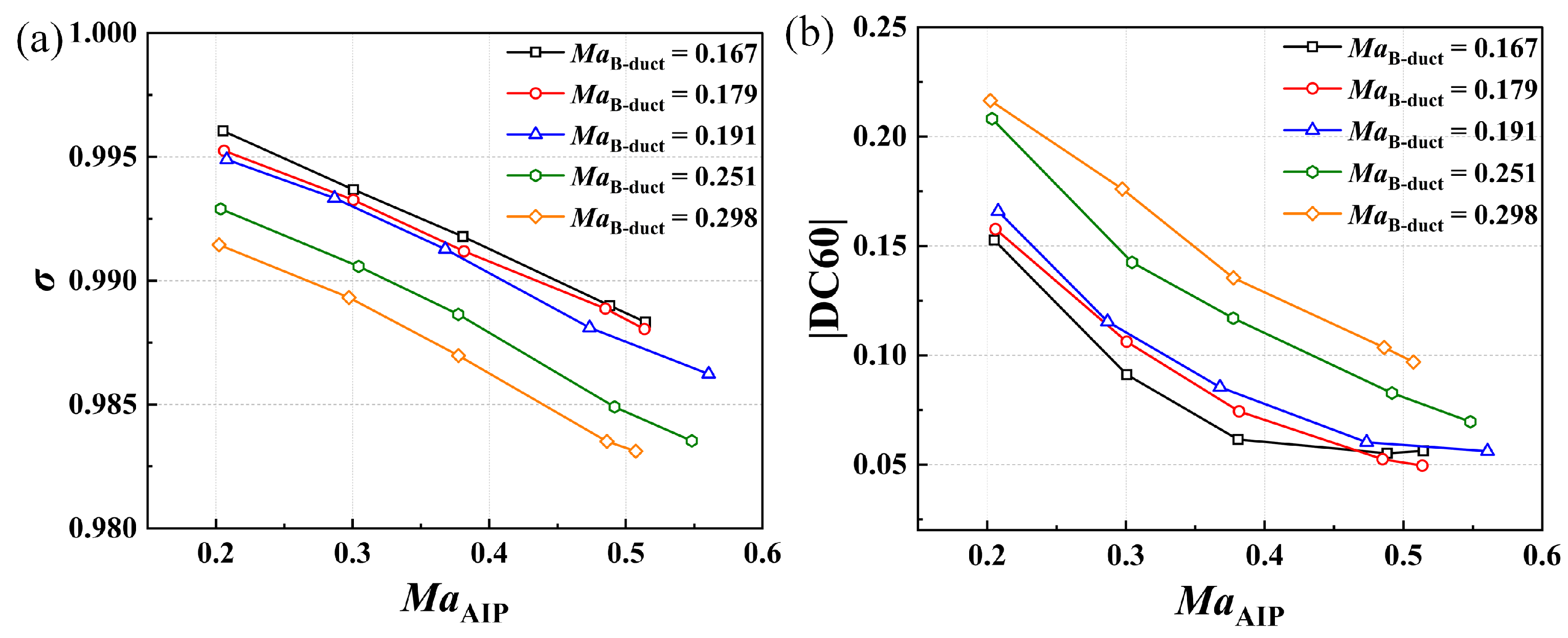
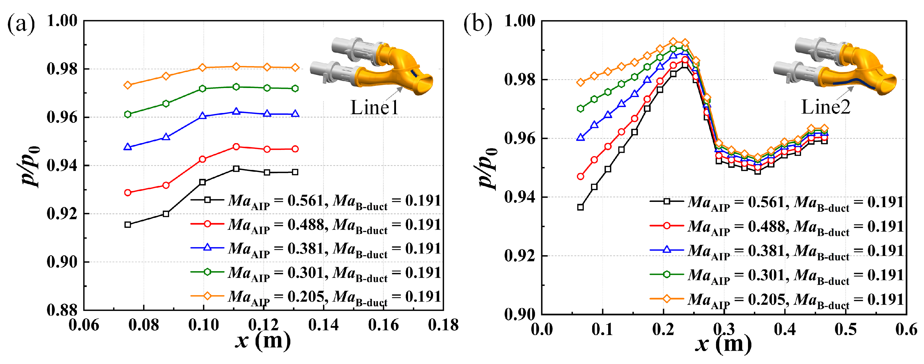
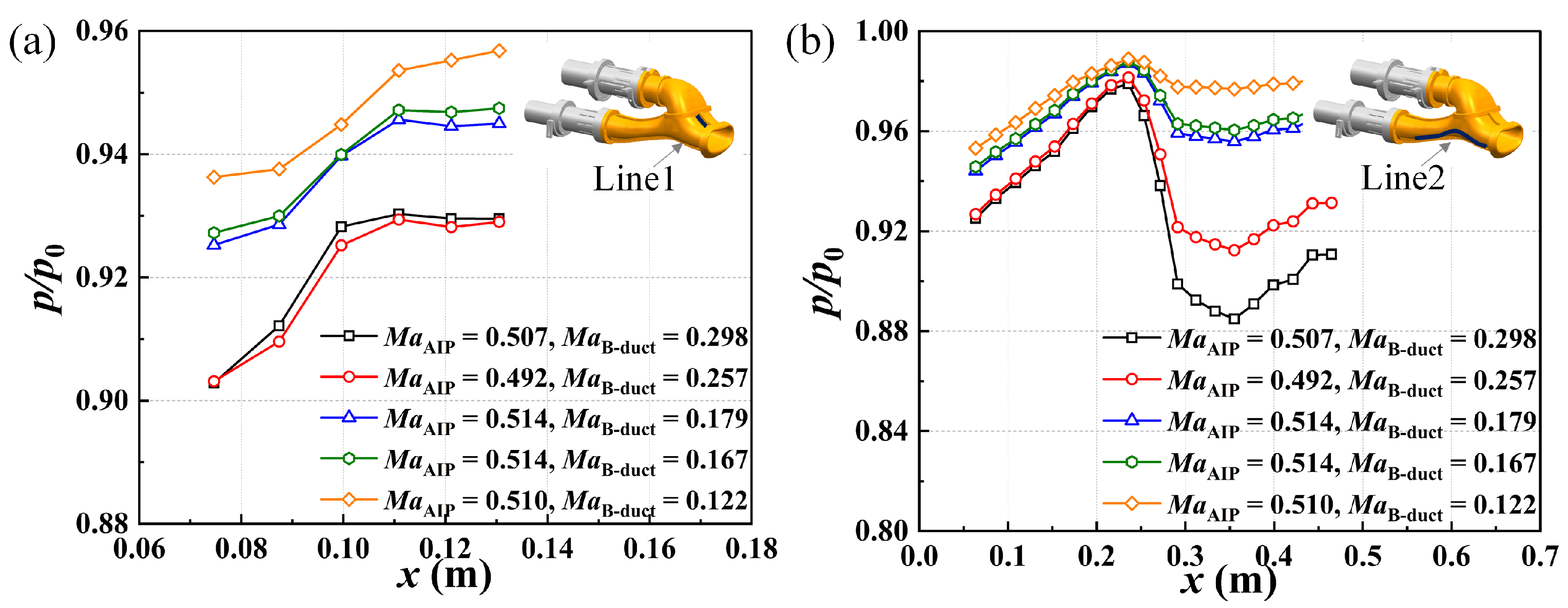
4.1. Aerodynamic Characteristics of the Inlet

By controlling the valves to adjust the suction pressure downstream of the core duct and bypass duct, the performance of the inlet under different M a AIP and different M a B - duct is obtained. Table 3 and Figure 5 show the total pressure recovery coefficient σ and total pressure distortion |DC60| of the AIP for different operating conditions, where the velocity of the freestream is 0 m/s. First, it can be found that σ and |DC60| decrease as M a AIP increases under ground suction conditions. The reason for the decrease in σ is that the static pressure level in the core duct decreases with the increase in engine operating parameters, which leads to an overall decrease in the quality of the outlet flow field, whereas the reason for the decrease in |DC60| is that the airflow in the inlet is mixed more quickly with the increase in engine operating parameters, which leads to a decrease in the uniformity of the airflow. Second, M a B - duct has a significant effect on the aerodynamic performance of the branched turboprop inlet. As M a B - duct increases, σ decreases, |DC60| increases, and the inlet aerodynamic performance decreases significantly. In addition, the friction loss in the inlet increases with M a AIP and M a B - duct increasing, which also contributes to the decrease in σ of the inlet.
Figure 6 shows the distribution of the static pressure along the inlet when M a B - duct = 0.191 and M a AIP is different, whereas the distribution of the static pressure along the inlet when M a AIP ≈ 0.5 and M a B - duct is different is shown in Figure 7. First, it can be seen from Figure 6 that as M a B - duct increases, the static pressure along Line1 and Line2 generally decreases. Similarly, it is also seen from Figure 7 that as M a B - duct increases, the static pressure along Line1 and Line2 decreases. In addition, it can be found from Figure 7 that the static pressure along Line1 when M a B - duct = 0.257 is smaller than that when M a B - duct = 0.298, which is due to the small difference of M a AIP . It also indicates that there is a coupling effect between the core duct and the bypass duct.

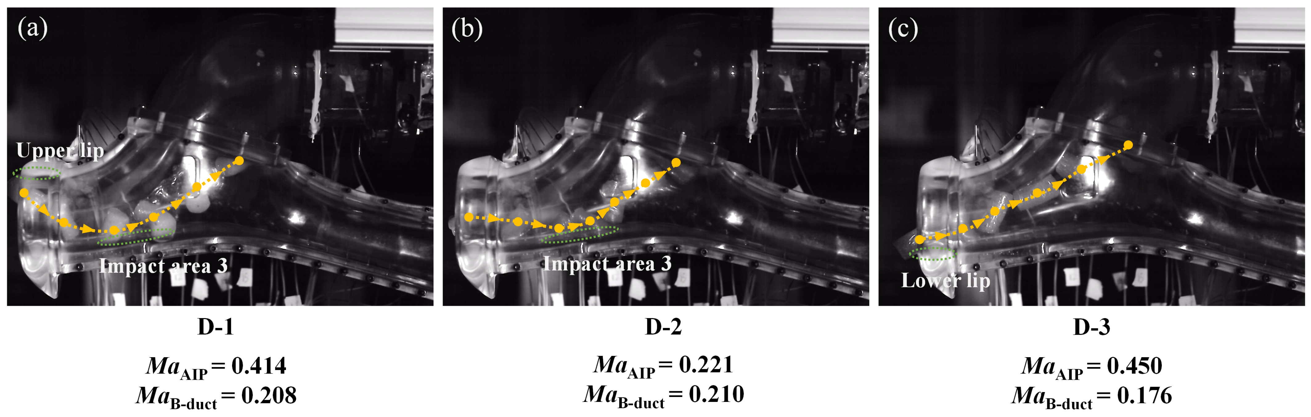
4.2. Exclusion Characteristics of the Inlet

By changing the suction pressure downstream of the core duct and bypass duct, the motion of bird dummies in the inlet under different M a AIP and different M a B - duct is obtained. Table 4 shows the motion and exclusion of the bird dummy in the inlet under ground suction conditions with different engine operating parameters. In Table 4, the repeatability tests were conducted for several operating conditions. The nominal M a AIP and the nominal M a B - duct for Cases 4, 5, and 6 are 0.35 and 0.2, respectively. The nominal M a AIP and the nominal M a B - duct for Cases 7 and 8 are 0.3 and 0.2, respectively. The nominal M a AIP and the nominal M a B - duct for Cases 9, 10, and 11 are 0.25 and 0.2, respectively. It can be found that the exclusions are all the same when the incident angle of the bird is similar. When the incident angle of the bird is more than 13°, it is easy for it to enter the core duct.
Furthermore, it is seen from Table 4 that there are three cases in which the bird dummy enters the core duct in all the tests. Moreover, there are four categories (A, B, C, and D) of impacting outcomes for the bird. A, B, and C are the situations in which the bird enters the bypass duct, and D is the situation in which the bird enters the core duct. The first category is that the bird impacted the bulge of the bypass duct, then impacted the lower surface of the diverter, and entered the bypass duct (A) in Cases 1, 4, 5, 7, 8, 9, 12, 13, 15, and 16, as indicated in Figure 8a. It is worth noting that Figure 8 shows the position of the bird dummy at intervals of 7.5 ms. The second category is that the bird impacted the upper lip, then impacted the bulge of the bypass duct, then impacted the lower surface of the diverter, and entered the bypass duct (B) in Case 2, as indicated in Figure 8b. The third category is that the bird impacted the lower surface of the diverter, and then entered the bypass duct (C) in Cases 6 and 10, as indicated in Figure 8c. The motion patterns entering the bypass duct of the three categories are summarized in Figure 9.
The fourth category is that the bird entered the core duct (D) in Cases 3, 11, and 14, which consists of three specific situations: (1) the bird entered the core duct without any contact with the wall in Case 3, as indicated in Figure 10a; (2) the bird impacted the upper lip, then impacted the lower wall of the inlet, and entered the core duct in Case 11, as indicated in Figure 10b; and (3) the bird impacted the lower lip, then entered the core duct in Case 14, as indicated in Figure 10c. Notably, Figure 10 shows the position of the bird dummy at intervals of 7.5 ms. The motion patterns entering the core duct of the three situations are summarized in Figure 11.
In addition, it can be found by comparing Figure 8 and Figure 10 that under the three situations of entering the bypass duct, the position where the bird impacts the wall of the inlet is relatively far away from the lower lip. However, under the three situations of entering the core duct, the bird always impacted the wall of the inlet near the lower lip, either in the first collision or the second collision. Therefore, for the birds that dive downward, the profile of the lower surface of the inlet has a greater impact on the exclusion performance of the inlet. In the future, the lower surface of the inlet can be optimized and designed by using the parametric design method in the literature [6].

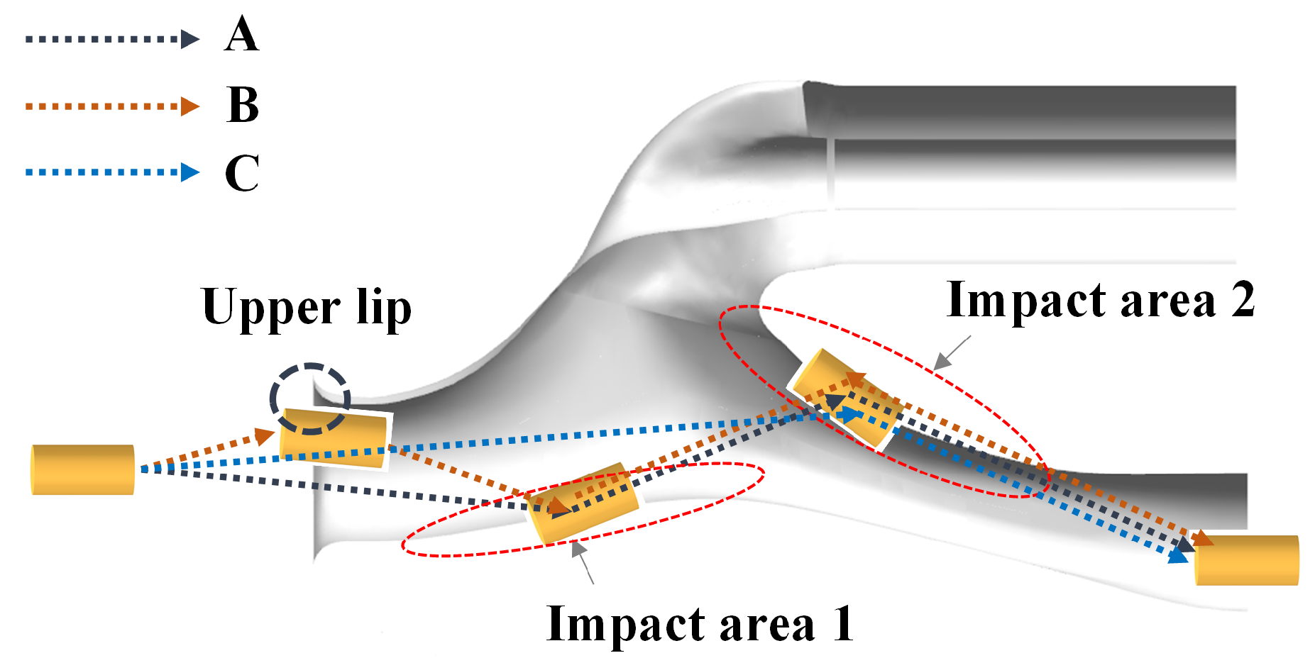
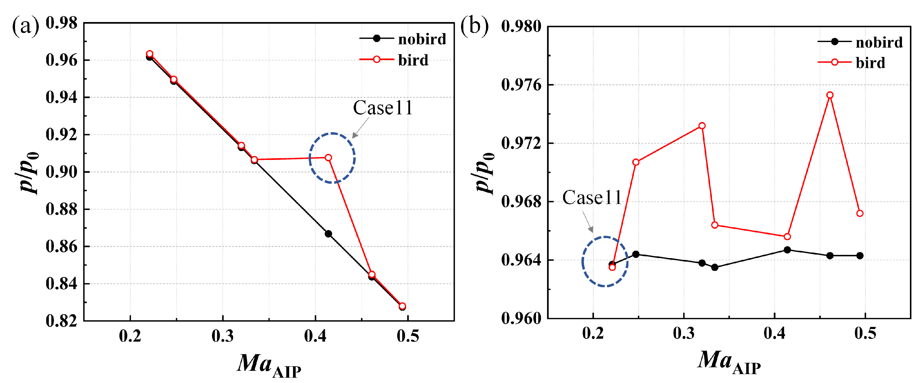
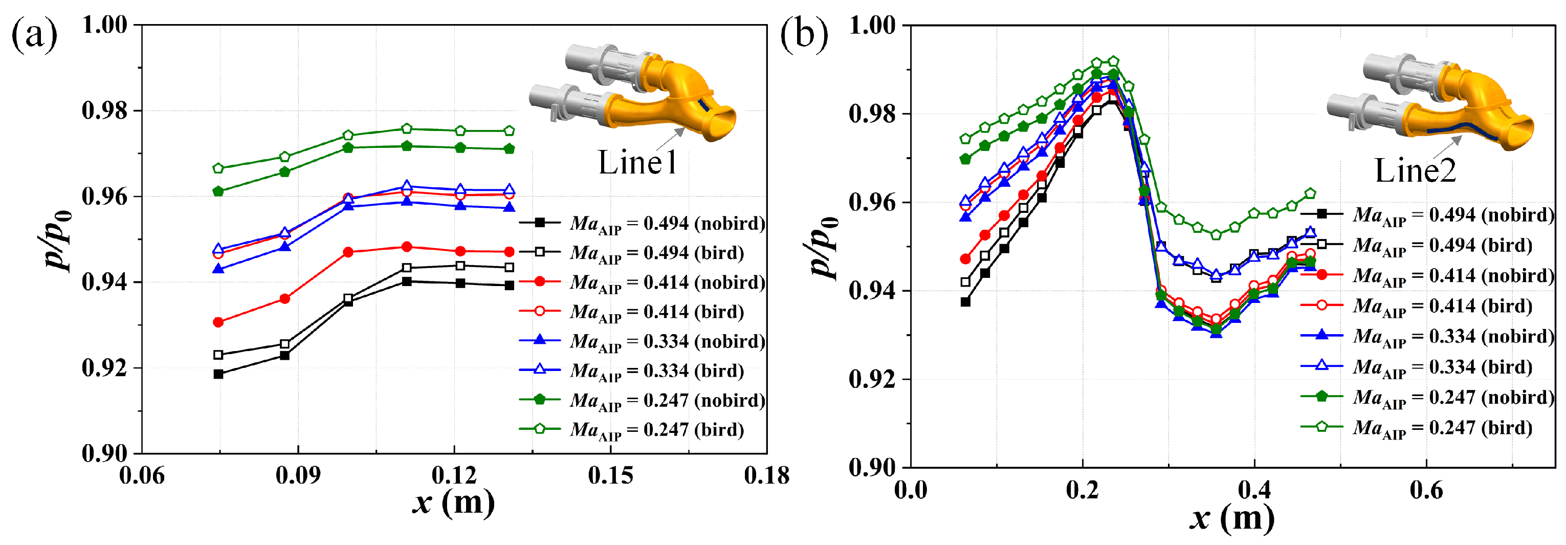
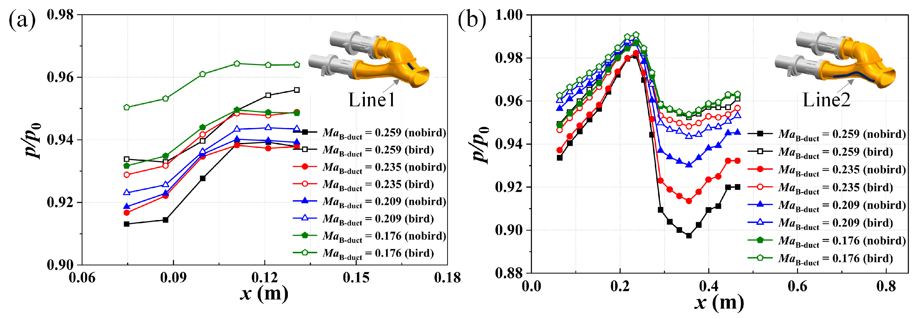
4.3. Aerodynamic Effects of the Bird on the Inlet

Table 5 provides the time-averaged results of the static pressure at the outlet with and without the bird dummy under ground suction conditions, whereas Figure 12 and Figure 13 compare the static pressure at the outlet with and without the bird dummy at different M a AIP and M a B - duct , respectively. It can be found that when the bird dummy enters the bypass duct, the static pressure of its outlet increases significantly, and the static pressure at the outlet of the core duct also increases slightly. The reason for this is that there is a blocking effect of the bird dummy on the airflow, and the flow rate in the bypass duct decreases significantly. Similarly, when the bird dummy enters the core duct, the static pressure at the outlet of the core duct increases significantly, and the static pressure at the outlet of the bypass duct increases slightly.
Figure 14 and Figure 15 compare the static pressure along the inlet with and without the bird dummy ( M a B - duct ≈ 0.21) in the inlet with different M a AIP , and the static pressure along the inlet with and without the gelatin bird ( M a AIP ≈ 0.45) in the inlet with different M a B - duct , respectively. The static pressure along the inlet with the presence of the bird dummy is a time-averaged result from the time of entry of the bird dummy into the inlet up to the exclusion process.
It can be observed from Figure 14 and Figure 15 that the static pressures on Line1 and Line2 increase during the motion of the bird dummy in the inlet, regardless of which duct the bird dummy enters. The reason for this is that when the bird enters the inlet, it blocks the flow in the inlet, which leads to a reduction in the flow velocity in the inlet. Furthermore, for the case where the bird enters the bypass duct, when the bird enters the inlet, the increase in pressure on Line1 is small, the increase in pressure on the first half of Line2 (x < 0.25) is small, and the increase in pressure on the second half of Line2 (x > 0.25) is large, which can indicate that the bird enters the bypass duct through the perspective of the aerodynamics as well. For the case of the bird entering the core duct, after the bird enters the inlet, the increase in pressure on Line1 is larger, the increase in pressure in the first half of Line2 (x < 0.2) is larger, and the increase in pressure in the second half of Line2 (x > 0.2) is smaller. Therefore, it can be concluded that when the bird moves into the inlet, the static pressure on the wall of the area where it passes through increases.
Overall, birds entering the core duct mainly have a significant effect on the static pressure at the outlet and the static pressure along the core duct, while having little effect on the bypass duct. Conversely, birds entering the bypass duct mainly have a significant effect on the static pressure at the outlet and the static pressure along the bypass duct, while having little effect on the core duct.

5. Conclusions

This paper presents an experimental study of the aerodynamic and bird exclusion characteristics of a branched turboprop inlet on a branched turboprop inlet–bird striking experiment system under ground suction conditions. Its ingestion outcomes were captured and monitored by a high-speed camera system, and the aerodynamic effects of the bird were monitored by a pressure measurement device. The conclusions are as follows:
(1) As M a AIP increases, σ and |DC60| gradually decrease when M a B - duct is certain under ground suction conditions. However, when M a AIP keeps constant, σ gradually decreases and |DC60| gradually increases as M a B - duct increases. Moreover, as both M a AIP and M a B - duct increase, the static pressure along the inlet decreases.
(2) The exclusion of birds is most significantly affected by the incident angle, with all birds excluded at incident angles less than 10°. The motion of the bird dummy entering the bypass duct within the inlet is described in three categories, “impacting the bulge of the bypass duct–impacting the lower surface of the diverter–entering the bypass duct”, “impacting the upper lip–impacting the bulge of the bypass duct–impacting the lower surface of the diverter–entering the bypass duct”, and “impacting the lower surface of the diverter–entering the bypass duct”.
(3) When a low speed bird at a large incident angle impacts on the wall of the inlet near the lower lip under ground suction conditions, the bird is easily sucked into the core duct. Conversely, it is more likely to be excluded by the bypass duct. The motion of the bird entering the core duct within the inlet can also be classified into three categories: “impacting the upper lip–impacting in front of the bulge of the bypass duct–entering the core duct”, “impacting in front of the bulge of the bypass duct–entering the core duct”, and “impacting the lower lip–entering the core duct”.
(4) The static pressure on the wall of the area where it passes through increases significantly as the bird is ingested into the inlet; birds entering the core duct mainly have a significant effect on the static pressure at the outlet and the static pressure along the core duct, while having little effect on the bypass duct. Conversely, birds entering the bypass duct mainly have a significant effect on the static pressure at the outlet and the static pressure along the bypass duct, while having little effect on the core duct.

Author Contributions

Conceptualization, G.Z. and Z.W.; methodology, G.Z. and Z.W.; software, G.Z.; validation, G.Z.; formal analysis, Z.W.; investigation, G.Z.; resources, H.T.; data curation, G.Z.; writing—original draft preparation, G.Z.; writing—review and editing, Z.W.; visualization, G.Z.; supervision, Z.W.; project administration, H.T.; funding acquisition, H.T. All authors have read and agreed to the published version of the manuscript.

Funding

This study was supported by the Civil Airplane Technology Development Program of China (No. MJ-2020-F-10).

Data Availability Statement

The data presented in this study are available on request from the corresponding author.

Conflicts of Interest

The authors declare that they have no conflicts of interest in this work.

Nomenclature

A 0 Inlet throat area
A 1 Core duct exit area
A 2 Bypass duct exit area
DC60Total pressure distortion index
kRatio of specific heat of air
L b Bird dummy length
L 1 Distance of entrance from the AIP
M b Bird dummy weight
M a AIP Mach number at the AIP
M a B - duct Mach number at the outlet of the bypass duct
p AIP Average static pressure at the AIP
p AIP * Average total pressure at the AIP
p B - duct Average static pressure at the outlet of the bypass duct
p B - duct * Average total pressure at the outlet of the bypass duct
p 0 Freestream static pressure
p 0 * Freestream total pressure
p min 60 * Minimum total pressure in any sector region with the azimuthal angle of 60°
q a v Average dynamic pressure at the AIP
R 1 Core duct outside radius
R 2 Bypass duct radius
r 1 Core duct inside radius
V bird Incident velocity of the bird
α bird Incident angle of the bird
σ Total pressure recovery coefficient
AIPAerodynamic interface plane
CFDComputational fluid dynamics
ESPElectronically scanned pressure
FOEForeign object exclusion
PSIPRESSURE SYSTEMS INTERNATIONAL INC.
6–DOFSix–degree–of–freedom

References

  1. Balli, O.; Hepbasli, A. Energetic and exergetic analyses of t56 turboprop engine. Energy Convers. Manag. 2013, 73, 106–120. [Google Scholar] [CrossRef]
  2. Aygun, H. Effects of air to fuel ratio on parameters of combustor used for gas turbine engines: Applications of turbojet, turbofan, turboprop and turboshaft. Energy 2024, 305, 132346. [Google Scholar] [CrossRef]
  3. Voskuijl, M.; Van Bogaert, J.; Rao, A.G. Analysis and design of hybrid electric regional turboprop aircraft. CEAS Aeronaut. J. 2018, 9, 15–25. [Google Scholar] [CrossRef]
  4. Saravanamuttoo, H. Modern turboprop engines. Prog. Aerosp. Sci. 1987, 24, 225–248. [Google Scholar] [CrossRef]
  5. Balli, O. Advanced exergy analyses of an aircraft turboprop engine (tpe). Energy 2017, 124, 599–612. [Google Scholar] [CrossRef]
  6. Zheng, G.; Tan, H.; Wu, Z.; Zhang, F.; Zhang, Y.; Luo, G. Aerodynamics and bird ingestion characteristics of a bulge-adjustable turboprop engine inlet. Aerosp. Sci. Technol. 2024, 144, 108777. [Google Scholar] [CrossRef]
  7. Meguid, S.A.; Mao, R.H.; Ng, T.Y. FE analysis of geometry effects of an artificial bird striking an aeroengine fan blade. Int. J. Impact Eng. 2008, 35, 487–498. [Google Scholar] [CrossRef]
  8. Zhou, G.; Zhou, H.; Wu, Z.; Tan, H.; Qin, W. Ice object exclusion characteristics of turboshaft engine inlet under helicopter/inlet integration conditions. Aerospace 2024, 12, 458. [Google Scholar] [CrossRef]
  9. Mi, B. A CFD–CSD coupling method for simulating the dynamic impact and expulsion of fragile foreign objects from the ‘inlet–bypass duct’junction of a turboprop aircraft. Eng. Appl. Comput. Fluid Mech. 2022, 16, 73–94. [Google Scholar]
  10. Wu, Z.; Shi, Z.; Sun, S.; Tan, H. Two-phase flow characteristics inside a serpentine inlet in heavy rain. Phys. Fluids 2025, 37. [Google Scholar] [CrossRef]
  11. Li, C.; Bin, G.; Li, J.; Yang, P.; Wang, W. Influence of inlet distortion on the wear of aero-compressor blades. Int. J. Mech. Sci. 2022, 120, 107551. [Google Scholar] [CrossRef]
  12. Mohamed, B.; Ahmed, F.; Galal, B. Effect of erodent particle initial velocity on the erosion of propeller blades for turboprop engines. In Proceedings of the 27th Joint Propulsion Conference, Sacramento, CA, USA, 24–26 June 1991. [Google Scholar]
  13. Mohamed, B.; Ahmed, F.; Galal, B. Numerical simulation of the aerodynamic behavior of propeller blades at subsonic conditions. In Proceedings of the 27th Joint Propulsion Conference, Sacramento, CA, USA, 24–26 June 1991. [Google Scholar]
  14. Zhou, H.; Wu, Z.; Tan, H.; Zheng, G.; Zhang, F.; Luo, G.; Chen, W. Numerical simulation on bird ingestion characteristics from engine inlet of turboprop aircraft. J. Aerosp. Power 2024, 39, 202300831. [Google Scholar]
  15. Zhang, D.; Fei, Q. Effect of bird geometry and impact orientation in bird striking on a rotary jet-engine fan analysis using SPH method. Aerosp. Sci. Technol. 2016, 54, 320–329. [Google Scholar] [CrossRef]
  16. Mao, R.H.; Meguid, S.A.; Ng, T.Y. Finite element modeling of a bird striking an engine fan blade. J. Aircr. 2007, 44, 583–596. [Google Scholar] [CrossRef]
  17. Zheng, G.; Wu, Z.; Tan, H.; Zhang, Y.; Wang, K. Design and examination of a turboprop inlet with scavenge duct. Chin. J. Aeronaut. 2023, 36, 32–42. [Google Scholar] [CrossRef]
  18. Barta, A.; Bennett, W.; Vittal, B.; Krishnan, M. Design and development of a compact bifurcated turboprop inlet. In Proceedings of the 27th Joint Propulsion Conference, Sacramento, CA, USA, 24–26 June 1991. [Google Scholar]
  19. Ruiz-Calavera, L.; Funes-Sebastian, D.; Perdones-Diaz, D. Powered model wind tunnel tests of a high-offset subsonic turboprop air intake. In Proceedings of the 46th AIAA/ASME/SAE/ASEE Joint Propulsion Conference & Exhibite, Nashville, TN, USA, 25–28 July 2010. [Google Scholar]
  20. Gula, P.; Ulma, D.; Zurek, K.; Zurawski, R. Challenges of turboprop engine installation on small aircraft. Aircr. Eng. Aerosp. Technol. 2019, 91, 938–948. [Google Scholar] [CrossRef]
  21. Zheng, G.; Wu, Z.; Tan, H.; Ren, J.; Zhang, Y.; Zhou, G. Aerodynamic study of a bifurcated turboprop engine inlet with a propeller for flow at ground suction conditions. Aerosp. Sci. Technol. 2024, 155, 109720. [Google Scholar] [CrossRef]
  22. Luo, G.; Xu, Z.; Shen, H.; Chen, W.; Zhang, H. Experimental study on the impact load of internally supported gelatin bird projectiles. Eng. Fail. Anal. 2021, 124, 105336. [Google Scholar] [CrossRef]
  23. Luo, G.; Mo, Y.; Wu, C.; Zhang, F.; Liu, L.; Chen, W. Experimental study of ice impact on aluminium/carbon fiber reinforced composite dual plate. Int. J. Crashworthiness 2022, 27, 510–521. [Google Scholar] [CrossRef]
  24. Luo, G.; Zhang, F.; Xu, Z.; Zhang, H.; Liu, L.; Chen, W. Internal reinforcement mechanisms for gelatin bird projectiles for artificial bird impact tests. Mech. Adv. Mater. Struct. 2023, 30, 3075–3085. [Google Scholar] [CrossRef]
  25. Zhang, F.; Luo, G.; Zhang, H.; Cong, P.; Liu, L.; Chen, W. Experimental and numerical analysis study on the low and medium speed bird strike. Eng. Fail. Anal. 2024, 156, 107766. [Google Scholar] [CrossRef]
  26. Zhou, R.; Liang, B.; Yue, Z.; Yang, H.; Zou, C.; Zhang, F.; Chen, S. High fidelity simulations of bird impact damages of a 5 MW wind turbine composite blade using SPH and damage models. Thin-Walled Struct. 2025, 208, 112835. [Google Scholar] [CrossRef]
  27. Papadakis, M.; Yeong, H.; Suares, I.; Jacob, J. Experimental and computational investigation of ice shedding from aircraft surfaces. In Proceedings of the 44th AIAA Aerospace Sciences Meeting and Exhibit, Reno, NV, USA, 9–12 January 2006. [Google Scholar]
  28. Papadakis, M.; Yeong, H.; Suares, I. Simulation of ice shedding from a business jet aircraft. In Proceedings of the 45th AIAA Aerospace Sciences Meeting and Exhibit, Reno, NV, USA, 8–11 January 2007. [Google Scholar]
  29. Papadakis, M.; Yeong, H.; Shimoi, K.; Wong, S. Ice shedding experiments with simulated ice shapes. In Proceedings of the 1st AIAA Atmospheric and Space Environments Conference, San Antonio, TX, USA, 22–25 June 2009. [Google Scholar]
  30. Mi, B.; Zhan, H. Numerical simulation on rigid foreign object exclusion in the turboprop engine intake system with a bypass duct. IEEE Access 2019, 7, 61920–61933. [Google Scholar] [CrossRef]
  31. Wang, L.; Zhang, Y.; Mi, B.; Yang, M. Numerical simulation on excluding foreign objects from engine inlet of turboprop aircraft. Adv. Aeronaut. Sci. Eng. 2020, 11, 264–271. [Google Scholar]
  32. Park, C.Y.; Jang, B.W.; Kim, J.H.; Kim, C.G.; Jun, S.M. Bird strike event monitoring in a composite UAV wing using high speed optical fiber sensing system. Compos. Sci. Technol. 2012, 72, 498–505. [Google Scholar] [CrossRef]
  33. Chen, X.; Liu, J.; Jiang, C.; Zhao, Z.; Zhang, H.; Zhang, C.; Li, Y. Evaluation of a substitute bird for engine fan blade impact tests considering the bird-slicing state. Eng. Fail. Anal. 2025, 167, 109056. [Google Scholar] [CrossRef]
  34. Lavoie, M.; Gakwaya, A.; Ensan, M.N.; Zimcik, D.; Nandlall, D. Bird’s substitute tests results and evaluation of available numerical methods. Int. J. Impact Eng. 2009, 36, 10–11. [Google Scholar] [CrossRef]
Figure 1. Test model.
Aerospace 12 00640 g001
Figure 2. Experimental system: (a) branched turboprop inlet–bird striking experiment setup; (b) launcher structure; (c) pressure measurement device; (d) high-speed camera system.
Aerospace 12 00640 g002
Figure 3. Bird dummy model.
Aerospace 12 00640 g003
Figure 4. Process of the bird dummy preparation.
Aerospace 12 00640 g004
Figure 5. Aerodynamic performance of the inlet at different M a AIP and M a B - duct : (a) σ ; (b) |DC60|.
Aerospace 12 00640 g005
Figure 6. Static pressure along the inlet at different M a AIP : (a) Line1; (b) Line2.
Aerospace 12 00640 g006
Figure 7. Static pressure along the inlet at different M a B - duct : (a) Line1; (b) Line2.
Aerospace 12 00640 g007
Figure 8. Three categories of impacting outcomes for the bird dummy entering the bypass duct: (a) A; (b) B; (c) C.
Aerospace 12 00640 g008
Figure 9. Illustration of the motion of the bird entering the bypass duct in the inlet.
Aerospace 12 00640 g009
Figure 10. Three categories of impacting outcomes for the bird dummy entering the core duct: (a) D-1; (b) D-2; (c) D-3.
Aerospace 12 00640 g010
Figure 11. Illustration of the motion of the bird entering the core duct in the inlet.
Aerospace 12 00640 g011
Figure 12. Comparison of static pressure at the outlet with and without the bird dummy at different M a AIP : (a) outlet of the core duct; (b) outlet of the bypass duct.
Aerospace 12 00640 g012
Figure 13. Comparison of static pressure at the outlet with and without the bird dummy at different M a B - duct : (a) outlet of the core duct; (b) outlet of the bypass duct.
Aerospace 12 00640 g013
Figure 14. Comparison of static pressure with and without the bird dummy along the inlet at different M a AIP . (a) Line1; (b) Line2.
Aerospace 12 00640 g014
Figure 15. Comparison of static pressure with and without the bird dummy along the inlet at different M a B - duct . (a) Line1; (b) Line2.
Aerospace 12 00640 g015
Table 1. Geometry parameters of the test model.
ParameterUnitsValue
Core duct outside radius,  R 1 mm48.3
Core duct inside radius,  r 1 mm19
Bypass duct radius,  R 2 mm43
Distance of entrance from AIP,  L 1 mm352.8
Inlet throat area,  A 0 mm213,000
Core duct exit area,  A 1 mm26195
Bypass duct exit area,  A 2 mm25809
Table 2. Geometry parameters of the bird dummy.
ParameterUnitsValue
Bird dummy length, L b m0.048
Bird dummy weight, M b kg0.021
Table 3. AIP performance of the test results.
Run Ma AIP Ma B - duct σ |DC60|
10.5140.1670.98830.0563
20.4880.1670.98900.0551
30.3810.1670.99180.0615
40.3010.1670.99370.0911
50.2050.1670.99600.1526
60.5140.1790.98800.0496
70.4850.1790.98890.0524
80.3820.1790.99120.0744
90.3000.1790.99330.1062
100.2060.1790.99520.1577
110.5610.1910.98620.0561
120.4740.1910.98810.0602
130.3680.1910.99130.0854
140.2870.1910.99330.1154
150.2080.1910.99490.1658
160.5480.2570.98350.0696
170.4920.2570.98490.0827
180.3770.2570.98860.1170
190.3040.2570.99060.1425
200.2030.2570.99290.2081
210.5070.2980.98310.0969
220.4860.2980.98350.1036
230.3770.2980.98700.1354
240.2970.2980.98930.1761
250.2020.2980.99140.2165
260.4410.3310.98320.1316
270.3810.3310.98530.1498
280.2850.3310.98860.1939
290.5100.1220.98970.0659
300.5330.1820.98710.0559
Table 4. The motion and exclusion characteristics of bird dummies in the inlet under ground suction conditions with different engine operating parameters.
Case V bird (m/s) α bird Ma AIP Ma B - duct OutcomeExcluded?
13.81−9.87°0.4940.208AYes
26.54−1.43°0.4610.209BYes
35.271.26°0.4140.208DNo
43.82−3.28°0.3550.215AYes
58.48−2.95°0.3340.211AYes
65.34−1.17°0.3330.200CYes
74.740.3200.210AYes
86.37−3.83°0.2830.205AYes
96.73−3.01°0.2470.208AYes
101.670.2210.202CYes
114.77−13.83°0.2210.210DNo
125.77−1.08°0.3520.173AYes
135.44−9.94°0.3530.263AYes
144.32−16.84°0.4500.176DNo
153.81−10.01°0.4620.235AYes
163.76−2.49°0.4520.259AYes
Note that in the outcome column, A represents “the bird dummy first impacted the bulge of the bypass duct, then impacted the lower surface of the diverter and entered the bypass duct”, B “the bird dummy first impacted the upper lip, then impacted the bulge of the bypass duct, and lastly impacted the lower surface of the diverter and entered the bypass duct”, C “the bird dummy impacted the lower surface of the diverter and entered the bypass duct”, D “the bird dummy entered the core duct”.
Table 5. Comparison of static pressure at the outlet under ground suction conditions with and without the bird dummy.
Case Ma AIP Ma B - duct p AIP / p 0 p B - duct / p 0 Is There a Bird?
10.4940.2080.82750.9643No
0.82800.9672Yes
20.4610.2090.84370.9643No
0.84500.9753Yes
30.4140.2080.86680.9647No
0.90770.9656Yes
40.3550.2150.89590.9622No
0.89610.9644Yes
50.3340.2110.90610.9635No
0.90660.9664Yes
60.3330.2000.90680.9673No
0.90670.9746Yes
70.3200.2100.91320.9638No
0.91420.9732Yes
80.2830.2050.93110.9654No
0.93180.9718Yes
90.2470.2080.94870.9644No
0.94970.9707Yes
100.2210.2020.96190.9665No
0.96290.9770Yes
110.2210.2100.96160.9637No
0.96340.9635Yes
120.3520.1730.89760.9758No
0.89860.9804Yes
130.3530.2630.89680.9465No
0.89970.9742Yes
140.4500.1760.84930.9750No
0.90280.9753Yes
150.4620.2350.84320.9555No
0.84510.9692Yes
160.4520.2590.84830.9477No
0.85190.9718Yes
Disclaimer/Publisher’s Note: The statements, opinions and data contained in all publications are solely those of the individual author(s) and contributor(s) and not of MDPI and/or the editor(s). MDPI and/or the editor(s) disclaim responsibility for any injury to people or property resulting from any ideas, methods, instructions or products referred to in the content.

