Abstract
Flight mechanics/dynamics models are essential for analyzing aircraft flight performance, where aerodynamic data play a critical role. This paper establishes a missile flight dynamics model and investigates the influence of aerodynamic modeling errors based on wind tunnel test data. Common aerodynamic modeling methods are compared, the effects of longitudinal coefficient deviations on the linearized missile model are analyzed using a deviation test approach, and the results are validated through simulations. The results show that interpolation-based aerodynamic modeling may lead to overfitting; segmented or denser Mach number testing is recommended to improve accuracy. Although aerodynamic error models based on derivatives and coefficients are applicable only within limited flight envelopes, they offer faster simulation and convenient uncertainty introduction. The missile’s longitudinal eigenvalue distribution is affected only by , , and . The frequency domain differences between lift and pitch control surface effects determine the system’s non-minimum phase behavior. Furthermore, aerodynamic uncertainties may increase overshoot risk in a closed-loop control system, highlighting the need for robust control design.
1. Introduction
The flight dynamics model serves as the primary subject for evaluating and improving aircraft flight performance, and it forms the foundation for the design and analysis of flight control laws [1,2,3,4,5,6,7]. The accurate modeling of dynamic behavior is of particular importance in this context. The aerodynamic characteristics of an aircraft represent the most critical input data for dynamic modeling and largely determine its fidelity. These characteristics are typically obtained through the following three main approaches: wind tunnel testing, numerical simulation, and flight testing. Among these, flight testing offers limited flexibility and is commonly employed for aerodynamic model validation [1,2,3,6,8,9]. Numerical simulation is widely applied in aerodynamic research [10,11,12], but suffers from limited accuracy in simulating flows around complex aerodynamic configurations. For aircraft aerodynamic modeling, wind tunnel testing remains the most reliable and widely adopted method. However, measurement errors are inevitable, and different aerodynamic modeling techniques based on test data can lead to significant discrepancies in the resulting models.
Current research on aerodynamic uncertainties primarily focuses on areas such as aerodynamic shape design and structural strength validation [13], with relatively limited attention given to their impact on flight quality and control performance. Although aerodynamic modeling under complex unsteady conditions—such as high angles of attack and aerodynamic hysteresis—has received considerable attention [14,15,16,17,18,19], studies on high-fidelity aerodynamic modeling and the influence of aerodynamic parameters on the characteristics of the flight dynamics model remain insufficient.
The uncertainties associated with accurate aerodynamic modeling mainly stem from two sources. First, wind tunnel testing inherently has limitations in fully and accurately replicating real flight conditions. Instrumentation limitations—including calibration errors of the wind tunnel, sensors, force balances, and characteristic size measurements—inevitably introduce uncertainties into the test results. Furthermore, wind tunnel wall interference and sting support interference can disrupt the flow field and compromise model integrity [20,21,22]. Additionally, employing different test configurations may yield substantially divergent data; for instance, NASA’s Common Research Model (CRM) standard configuration exhibits significant variations in model moments and drag distribution across different wind tunnels (employing different balances and supports) [20]. Moreover, the limitations inherent in scaled models, such as insufficient test Reynolds numbers and difficulties in simulating power effects, introduce further deviations into the experimental results. Extensive research has been conducted in this area, yielding promising results. Second, when constructing aerodynamic models based on wind tunnel test databases, interpolation methods or aerodynamic derivative coefficient methods are commonly used to ensure continuity as the experimental data consist of discrete points across multiple independent variables (e.g., aircraft configuration, Mach number, angle of attack, sideslip angle, Reynolds number, and control surface deflections) [8,23]. Interpolation methods may suffer from reduced accuracy when raw aerodynamic data are sparsely distributed or when aerodynamic characteristics exhibit sharp variations in certain flight regimes. In contrast, aerodynamic derivative coefficient models are well-suited for most engineering applications as they can be directly coupled to small-disturbance linearized equations. However, their accuracy and applicability diminish in nonlinear flight conditions, such as those involving large attitude angles or significant control surface deflections [24,25,26].
In the study of aerodynamic model errors, researchers typically employ either theoretical derivation based on the modeling process or the numerical simulation of the entire system. For instance, several studies have conducted parameter sensitivity analyses on flight dynamics systems to evaluate control system designs [27,28,29], provide guidance for parameter identification [30], or support the optimization of control strategies [13]. In numerical validation tests, stochastic robustness methods—such as Monte Carlo simulations [31,32,33]—are frequently used in control law verification to assess the effects of uncertainties in system parameters. For instance, Reference [32] demonstrates the application of a Monte Carlo analysis to evaluate the impact of uncertainties in dynamic parameters on the flight modes of the small unmanned aerial vehicle Gemini V2. Based on this analysis, the study further refined the UAV’s navigation logic. Separately, Reference [33] focuses on Mars entry, descent, and landing (EDL) missions. By benchmarking against a six-degree-of-freedom linear covariance (6-DoF LinCov) analysis, this work validates the applicability and utility of the Monte Carlo method for the verification and analysis of dynamic systems. However, most existing studies analyze deviations across all input parameters of the dynamics model or the entire system, focusing primarily on overall system performance rather than isolating the specific influence of aerodynamic data. Therefore, it is essential to investigate how aerodynamic model errors affect flight dynamics characteristics. Such insights can inform improvements in flight dynamics modeling, control law design, and target enhancements in wind tunnel testing and data processing methodologies.
To address these issues, this study investigates the key aspects of aerodynamic modeling for a typical missile configuration. It analyzes discrepancies arising from different modeling approaches and evaluates the impact of longitudinal aerodynamic model errors on missile dynamics through systematic parameter deviation studies. Simulations of both open-loop and closed-loop systems under various aerodynamic error scenarios were conducted. Based on the results, recommendations are provided for improving wind tunnel testing procedures and aerodynamic modeling practices.
2. Modeling and Methodology
This study focuses on a typical missile configuration (Figure 1), comprising a fuselage, wings, and tail fins arranged in an “X” configuration. The missile features a body length of approximately 1.5 m and a diameter of about 0.2 m. The selected layout is relatively simple, yet shares comparable flight dynamic characteristics and control law design principles with many high-speed missile variants, thereby providing broad representativeness. Flight control is primarily achieved through combined deflections of the four tail fins (rudders), as follows:
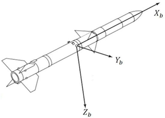
Figure 1.
Sketch view of a missile.
- Pitch control (via elevators, ): Deflection of 4 rudder trailing edges upward or downward.
- Yaw control (via rudder, ): Deflection of 4 rudder trailing edges left or right.
- Roll control (via ailerons, ): Deflection of 4 rudder trailing edges in the circumferential direction clockwise or counterclockwise.
2.1. Flight Dynamics Modeling
A flight dynamics model of the missile was developed using MATLAB Simulink R2023b (Figure 2). The inputs were the deflection angles of three tail fins (, , and ). The outputs included motion states such as position, velocity, acceleration, overload, attitude angles, angular rates, and angular accelerations. Within the model depicted in Figure 2, the following can be seen:
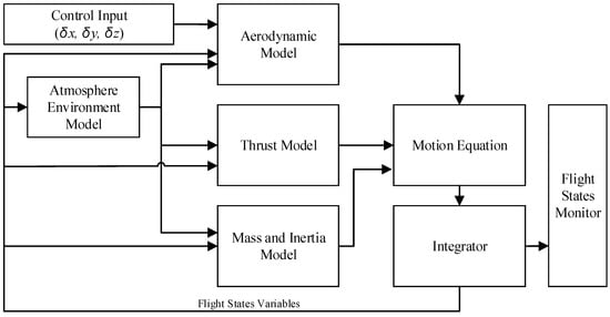
Figure 2.
Flight dynamics model of a missile.
- Atmospheric Environment Model: This provides essential parameters (speed of sound, air density, viscosity, and gravitational acceleration) as a function of flight altitude. These parameters serve as inputs to the aerodynamic, thrust, and mass/inertia models.
- Aerodynamic Model: This computes the resultant aerodynamic forces and moments based on the current flight state and control surface deflections.
- Thrust Model: This specifies the magnitude and direction of the propulsion force during the simulation.
- Mass and Inertia Model: This dynamically computes the missile’s weight (due to fuel consumption), center of gravity, and moments of inertia, accounting for variations over time and environmental conditions.
- Equation of Motion and an Integrator: These propagate the missile’s flight state (position, velocity, attitude, and angular rates) by integrating the forces, moments, and mass/inertia properties.
For the dynamic analysis and control system design, the complex model was linearized. Trim points were identified through force equilibrium analyses and linearized small-disturbance equations were derived near these points. The linear state-space model is expressed as follows:
For longitudinal motion, the state vector includes the angle-of-attack perturbation and the pitch rate, whereas the input represents the elevator deflection. The sensor outputs include the normal overload and pitch rate. Matrices , , , and characterize the linearized dynamics.
For roll motion, the state vector includes the angle of roll and the roll rate, whereas represents the aileron deflection. The sensor outputs include the roll angle and roll rate.
2.2. Aerodynamic Modeling
The aerodynamic model is the core of a flight dynamics model and is one of the main sources of errors in a flight simulation model. In this study, aerodynamic data were obtained primarily through wind tunnel tests. The aerodynamic model can be divided into static and dynamic parts. The static aerodynamic input was the discrete point data of different test conditions (Mach number, angle of attack, sideslip angle, and rudder angle combination). To ensure the data remained continuous in modeling, the following two common methods were considered.
2.2.1. Aerodynamic Database Interpolation
Based on wind tunnel test data, multidimensional arrays of 6-component aerodynamic coefficients () with different test conditions were constructed, respectively, as follows:
A continuous static aerodynamic model was obtained through data interpolation, as follows:
Among the interpolation methods, this study compared the modeling effects of the following four methods: linear interpolation, cubic spline curve interpolation (spline) [34], Hermite interpolation (Makima), and machine-learning-based Kriging interpolation (also known as Gaussian process regression (GPR)) [35].
2.2.2. Derivative Coefficient Model
The aerodynamic database interpolation method has high interpolation dimensions and many discrete data points. The aerodynamic coefficient is often summarized as a linear or conic form of the key guiding coefficient in the aerodynamic description of an aircraft. For example, the typical longitudinal aerodynamic characteristic parameters are , , , , , , etc. A continuous aerodynamic model can be constructed by interpolating aerodynamic parameters with discrete points under flight conditions. The major lift, drag, and moment coefficients are expressed as follows:
It should be emphasized that the model described above is valid only within flight regimes where the primary aerodynamic forces and moments (excluding drag) exhibit linear variations, such as within an angle-of-attack range of approximately ±5°. Significant model deviations might occur under high angle-of-attack conditions characterized by nonlinear aerodynamics.
For the axisymmetric missile configuration studied in this work, the lateral-directional flight mechanics characteristics exhibit fundamental similarity to the longitudinal dynamics. To streamline the research focus, the side force () and yawing moment () characteristics were excluded from the detailed investigation and, consequently, are omitted from Equation (4). The dynamic derivative of the missile longitudinal pitching motion was simplified as and superimposed with the static aerodynamic moment to obtain the pitching moment of the final motion.
2.3. Error Modeling
In addition to the aerodynamic force/moment coefficient measurement error obtained from the wind tunnel test, the generalized aerodynamic data error should include atmospheric environment errors such as density, sound velocity, flight velocity, the dimensional and atmospheric disturbance errors caused by the reference length and reference area, and other measurement errors. This study focuses on the aerodynamic coefficient results of the wind tunnel test given in the model design; therefore, the influence of other errors is not considered for the time being.
To verify the robustness of the control system, a stochastic robust analysis (SRA) is often used to analyze the errors caused by changes in the system parameters. In terms of aerodynamic errors, the static aerodynamic coefficient is often tested with a ±20% error band, whereas the pitch dynamic derivative is often biased with a ±50% error band. The error model is represented by the following:
In wind tunnel tests, the accuracy of the balance test is generally within ±0.4%, and the accuracy level of seven repeated force tests is also very high [36]. The error band given based on Equations (5) and (6) is wide enough to surpass the test error level, and sufficiently safe for the robustness test of the control system to cover the influence of aerodynamic error.
The missile configuration exhibits perfect bilateral symmetry in its longitudinal plane while maintaining rigorous axisymmetry about the central axis; thus, in the case of no rudder bias input, , , and should be 0. The deflection of the above parameters is equivalent to the deflection of the efficiency of , , and .
Given the large number of parameters requiring investigation, the Monte Carlo estimation method is commonly employed for stochastic robustness testing. This approach introduces random variations into the model parameters to assess their statistical impact on system behavior. The missile dynamics model can be divided into the following three directional components: pitch (longitudinal), yaw (lateral), and roll. For an axisymmetric missile configuration, the longitudinal and lateral dynamics are similar, while the roll channel is typically independent. In this study, only the longitudinal and roll dynamics are considered. Accordingly, the number of research parameters is reduced to 10, as defined in Equations (5) and (6). Biased testing was conducted on 7 static and 3 dynamic parameter combinations, based on the methodology outlined in Model (6). For each parameter, the following three test cases were considered: maximum deviation, minimum deviation, and no deviation. The total number of simulations is iterations.
3. Results and Discussion
Based on the wind tunnel test data of the missile, the modeling error and its influence on the dynamic characteristics of the missile were studied. The main analysis results are as follows.
3.1. Aerodynamic Model Comparison
First, different aerodynamic data interpolation methods were used to model the aerodynamic database generated under different test conditions. Figure 3 shows typical longitudinal aerodynamic characteristic curves obtained using different interpolation methods. The fitting results obtained by the four interpolation methods are basically the same when only the attitude angle and rudder angle are changed. Although the drag coefficient manifests gradual variations in both the subsonic and supersonic regions, it experiences rapid divergence accompanied by steep gradient transitions in the transonic region as the Mach number increases. This nonlinear parametric behavior directly induces overfitting in data-driven interpolation approaches, particularly evident in the cubic spline and Kriging interpolation methods. Therefore, to ensure the accuracy of flight mechanics simulation results, it is advisable to densify the Mach number of the benchmark longitudinal test data during the construction of the aircraft aerodynamic database or to adopt the sub-Mach number fitting method to mitigate model errors arising from interpolation.
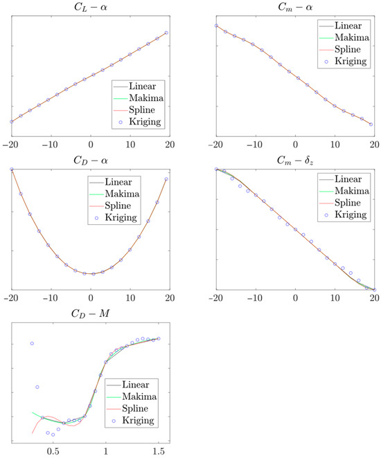
Figure 3.
Comparison of aerodynamic models of different interpolation methods.
From the perspective of model run time, the Kriging interpolation model puts the relevant parameters after fitting into the storage in advance, so the data prediction takes the least time overall (Table 1), which is more suitable for situations with high simulation speed requirements. However, in modeling, it may take several hours to pre-train and fit the database with large test data samples, and the fitted model parameters occupy a large storage space (in this case, up to 10 GB). The advantages and disadvantages of several interpolation methods are summarized in Table 2.

Table 1.
Comparison of model running time (5 × 10⁴ times; seconds).

Table 2.
Comparative analysis of data interpolation methods for database construction.
The model of Equation (4) can divide a single aerodynamic force/moment coefficient into two or three derivatives and bias coefficients. These derivatives are determined through linear regression within the aerodynamically linear regime (e.g., the low angle-of-attack region shown in Figure 3). This decomposition approach significantly reduces the dimensionality of the aerodynamic database, thereby dramatically accelerating the fitting speed of other interpolations, except linear interpolation is greatly improved (Table 1).
However, in terms of model fidelity, the aerodynamic derivative model exhibits notable limitations in meeting accuracy requirements across the entire flight envelope. This is primarily due to its reliance on linear or quadratic curve-fitting techniques, which may not adequately capture nonlinear aerodynamic behaviors. As shown in Figure 4, the aerodynamic predictions obtained using the derivative model show certain discrepancies when compared with the test results. Nevertheless, in most operational scenarios, the dynamic system operates within the linear region of aerodynamic forces, where the derivative model remains sufficiently accurate and applicable. Moreover, the error model defined by Equations (5) and (6), formulated in the same structure as the derivative model, offers a more consistent and rational approach. This formulation facilitates the superposition of aerodynamic errors in simulations and is particularly beneficial for robustness analyses of the control system as well as the evaluation of individual error sources. A comparative summary of the two modeling approaches is provided in Table 3.
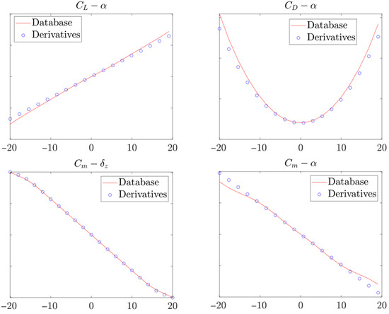
Figure 4.
Comparison of model precision using derivative model and aerodynamic database interpolation model with the linear method.

Table 3.
Comparative analysis of two aerodynamic modeling approaches.
3.2. Influence of Aerodynamic Errors
The missile dynamics simulation model shown in Figure 2 was linearized at representative trim points, and the deviation test model described by Equations (5) and (6) was superimposed to construct a state-space model (Equation (1)). The eigenvalue distribution of the system is presented in Figure 5. It can be observed that both the original and perturbed missile dynamics models all have eigenvalues located in the left half-plane, indicating that the system remained stable before and after the deviation tests. Among the seven longitudinal aerodynamic error parameters, only three—, , and —showed a noticeable influence on the distribution of characteristic roots. The blue arrows in the figure indicate the direction of eigenvalue movement caused by positive perturbations in these derivatives. The lengths of the arrows correspond with the magnitude of eigenvalue displacement induced by parameter variations, as defined in Equations (5) and (6). System stability is enhanced by increasing the values of these three derivatives. In particular, and are independent of each other, with primarily affecting the natural angular frequency and mainly influencing the damping ratio . In contrast, variations in the static stability derivative affect both and . The stability of the system is improved by increasing the three derivatives, among which the derivatives of and are independent and determined the natural angular frequency and damping ratio of the system, respectively, whereas the deviation of the static stability derivative interferes with both.
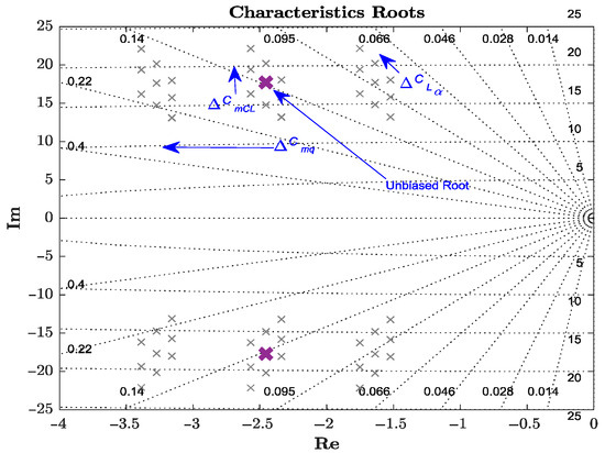
Figure 5.
Influence of aerodynamics offset on missile longitudinal dynamic characteristic roots.
The above three key aerodynamic derivatives also had a significant impact on the frequency domain characteristics of the model. As shown in Figure 6, the parameter perturbation (representing the pitch control surface efficiency error) induces proportional changes in the magnitude of the pitch rate across the entire control input frequency spectrum. However, its effect on the normal load factor is primarily confined to the mid- to low-frequency range (). In contrast, the perturbation (associated with variations in lift control surface efficiency) significantly affects the normal load factor response, but only in the high-frequency domain ().
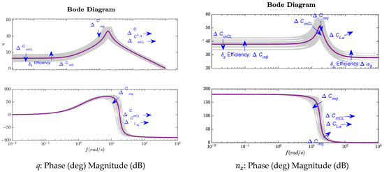
Figure 6.
Influence of aerodynamic derivative deviation on missile longitudinal dynamic logarithmic frequency characteristic.
In conventional missile control architectures, the roll channel typically operates independently with negligible dynamic cross-coupling to the longitudinal and directional channels. The magnitudes of and are small in comparison to and . Therefore, the influence of aerodynamic derivative deviations on the roll channel is primarily concentrated on two key derivatives, and . Figure 7 shows the eigenvalues of the rolling channel motion modes. The spiral mode can be categorized into the following two types: the spiral mode and the convergent mode. The spiral mode, characterized by a root close to the origin, exhibits critical stability behavior similar to the phugoid mode and remains largely unaffected by aerodynamic derivative deviations. In contrast, the convergent mode is influenced solely by the derivative , and its stability margin is directly proportional to the value of .
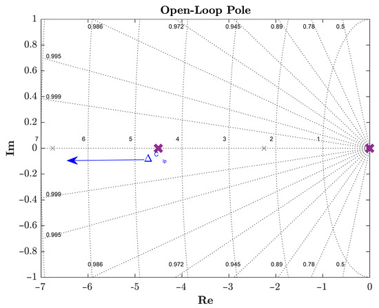
Figure 7.
Influence of aerodynamic model error on missile roll dynamic characteristic roots.
In terms of dynamic maneuverability, it can be observed from Figure 8 that the primary aerodynamic derivatives affecting the rolling channel characteristics of the missile are and ; other derivatives have a negligible influence on the frequency response characteristics. The deviation in roll control effectiveness, , affects the amplitude response across both high- and low-frequency ranges, but it does not influence the phase angle characteristics of the control input . In contrast, the damping derivative primarily affects the amplitude response at low frequencies while having a significant impact on the phase angle characteristics in the mid-frequency range.
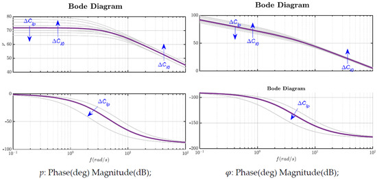
Figure 8.
Influence of aerodynamic derivatives on missile roll dynamic logarithmic frequency characteristics.
Based on the above analysis, Table 4 summarizes the influence patterns of errors in the primary aerodynamic derivatives and coefficients on the key characteristics of the missile dynamics model.

Table 4.
The influence of major aerodynamic derivatives and coefficients on the missile dynamics.
The above analysis is based on the linearized missile dynamics model. To further validate the findings, simulations and analyses were also conducted using the nonlinear missile dynamics model developed in Section 2.1. At the beginning of the simulation (), an initial angle of attack is introduced to excite the system under zero control input. Once the system converges and stabilizes, a step input of is applied at . Figure 9 illustrates the longitudinal open-loop response of the nominal missile model (in purple) and the variation range induced by aerodynamic parameter deviations (in gray). The model exhibits strong inherent stability, with both zero-input responses and responses to control surface disturbances decaying to near zero within 1 s.
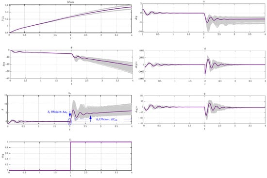
Figure 9.
Longitudinal open-loop response and error bands caused by aerodynamic parameter deviations.
The effects of the aerodynamic derivative deviations observed in the linear system eigenvalue analysis (Figure 5) are consistent with the time domain simulation results (Figure 9). Across various time domain performance metrics, the fundamental modal characteristics of the system remain largely unchanged. Deviation tests do not alter the overall stability of the system or the primary steady-state convergence values.
In the pitch control surface step input response, simulations that incorporate control surface effectiveness errors may result in significant response peaks. Therefore, particular attention should be paid to the accuracy of control surface effectiveness data obtained from wind tunnel tests as well as to the robustness of the control system design with respect to such errors. Notably, in the normal overload response to a step input of the control surface, an instantaneous reverse overload () occurs, and this peak is solely related to the deviation . This observation aligns with the pattern shown in Figure 6, where the lift control effectiveness () of affects only at high frequencies. After the control surface step input, the pitch control effectiveness of becomes the dominant factor influencing the output. Hence, errors in lift control effectiveness significantly impact the non-minimum phase characteristics of the missile.
Similarly, in the step input response of the pitch rudder, simulations with superimposed rudder surface efficiency errors may also lead to large response peaks. It is, therefore, essential to ensure the accuracy of rudder efficiency data in wind tunnel testing and to design a control system that is robust to such uncertainties. As observed in the normal overload response to the rudder step input, an instantaneous reverse overload () appears, and the magnitude of this peak is exclusively associated with the deviation in . This behavior is consistent with the findings in Figure 6, which indicate that the influence of the lift effectiveness () on is confined to the high-frequency range. Following the rudder step input, the pitch rudder effectiveness of becomes the primary factor affecting the output. Therefore, inaccuracies in lift control effectiveness can significantly alter the missile’s non-minimum phase behavior.
Regarding the drag coefficients, the two parameters and exhibit minimal influence on the short-period dynamics of the missile. However, they are highly relevant to the simulation of flight speed, particularly during high-speed flight. As shown in Figure 9, the missile exhibits a Mach number error exceeding 0.1 within the first 4 s after launch. Consequently, for accurate trajectory and range simulations or when evaluating missile flight performance through numerical modeling, it is crucial to maintain a high level of fidelity in the drag model.
Under the influence of roll damping, the angular velocity rapidly decays to zero when an initial roll rate is introduced, while the missile’s roll attitude angle remains neutral and unchanged (Figure 10). When a step input is applied to the roll control surface, the roll angular velocity remains stable. Therefore, the input serves as the roll angular velocity command and is proportional to .
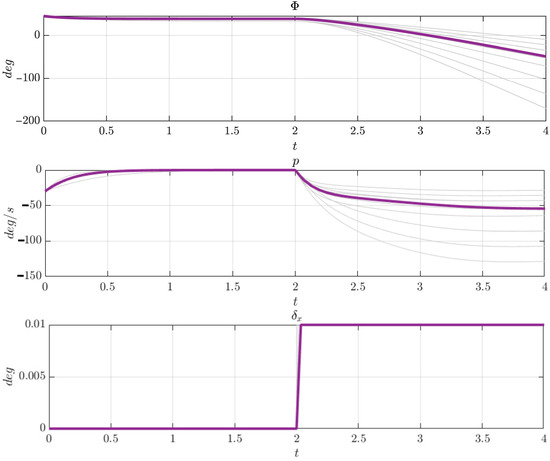
Figure 10.
Open-loop roll response of the missile and the associated error bands induced by aerodynamic parameter deviations.
For the design of controllers based on the small-perturbation linearized model of the missile, a three-loop control structure is adopted for the longitudinal channel (Figure 11), which is composed of the rate loop, synthetic stability loop, and accelerometer feedback loop with feedback gains , , and for each loop, respectively; is the control command gain. A PID controller is implemented for the roll channel (Figure 12), where is proportional gain and and are the integrator and derivative coefficients, respectively.

Figure 11.
Normal direction overload controller scheme [37].

Figure 12.
PID controller of rolling angle.
The control laws are defined by Equations (7) and (8). Building on the findings in Table 4 regarding the influence of key aerodynamic parameters on missile dynamics, controller parameter tuning prioritizes robustness against variations in the three dominant longitudinal stability derivatives. This approach yields optimized controller gains that ensure stable performance across operational uncertainties.
An aerodynamic derivative deviation test was conducted using the aforementioned method, and simulation results for the normal overload output under elevator and aileron step inputs were obtained, as shown in Figure 13. The settling time of the closed-loop system remains largely unaffected by these deviations. However, variations in roll control surface effectiveness, specifically , can significantly influence the system’s response time. Errors in the aerodynamic derivatives , , , and the dynamic damping derivative may lead to increased fluctuations in the normal overload output. These findings highlight the importance of careful missile structural design and robust control law development to mitigate the effects of such uncertainties.
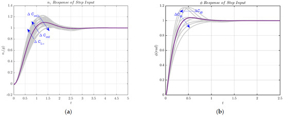
Figure 13.
Closed-loop response and error bands caused by aerodynamic deviations. (a) Longitudinal direction; (b) rolling direction.
4. Conclusions
This study establishes a quantitative causality chain linking wind tunnel measurement errors in mission-critical aerodynamic parameters to missile open/closed-loop flight dynamics and control stability. This breakthrough enables precision-targeted enhancements in aerodynamic testing protocols and modeling methodologies, thereby improving controller synthesis robustness and fulfilling the stringent requirements of next-generation missile systems. These advancements are substantiated by the following three key findings:
- (1)
- Validation is Imperative for Aerodynamic Database Modeling: Although interpolation-based aerodynamic databases enable efficient simulation and facilitate the incorporation of force/moment uncertainties, they carry a significant risk of overfitting and exhibit limited applicability beyond a narrow flight envelope. Rigorous validation of these models is, therefore, essential.
- (2)
- Critical Aerodynamic Derivatives Govern Longitudinal Dynamics: The longitudinal short-period dynamics of the missile are governed by the following three distinct aerodynamic derivatives: (static stability), (pitch damping), and (aerodynamic center shift). Each dominates different aspects of the dynamic response. Furthermore, lift and pitch control surfaces exert distinct frequency-band influences on normal overload. Crucially, the effectiveness of the lift control surface is the primary driver of the missile’s longitudinal non-minimum phase behavior.
- (3)
- Modeling Errors Pose Control System Risks: Inaccuracies within aerodynamic coefficient models can induce potential overshoot in the control system response. This finding underscores the critical importance of both robust controller design and high-fidelity aerodynamic modeling to ensure stable and predictable missile flight performance.
Author Contributions
Conceptualization, Q.L.; Data Curation, J.Z.; Formal Analysis, Q.L.; Funding Acquisition, J.Z.; Investigation, Q.L.; Methodology, Q.L.; Software, Q.L.; Supervision, J.Z.; Validation, Q.L.; Visualization, Q.L.; Writing—Original Draft, Q.L.; Writing—Review and Editing, X.Y. and J.Z. All authors have read and agreed to the published version of the manuscript.
Funding
This research was funded by National Natural Science Foundation of China grant number 62073185.
Data Availability Statement
The datasets presented in this article are not readily available because due to commercial limitations.
Conflicts of Interest
The authors declare no conflict of interest.
Glossary
The following nomenclatures are used in this manuscript:
| Angle of attack, deg | |
| Zero-lift angle of attack, deg | |
| State matrix (system dynamics) | |
| Sideslip angle, deg | |
| Input matrix (control input effect) | |
| Output matrix (state-to-output mapping) | |
| Coefficient related to any aerodynamic coefficient | |
| Lift curve slope (derivative of lift coefficient with respect to angle ), 1/deg | |
| Drag coefficient | |
| Zero-lift drag coefficient | |
| Zero-lift drag coefficient proportional to the square of lift coefficient | |
| Lift coefficient | |
| Roll moment coefficient | |
| Zero side force roll moment coefficient | |
| Angle-of-attack-induced roll moment coefficient | |
| Sideslip-induced roll moment coefficient | |
| Roll damping derivative (dimensionless roll rate) | |
| Zero-lift moment coefficient | |
| Moment coefficient related to lift coefficient | |
| Zero-lift moment coefficient | |
| Pitch damping derivative (dimensionless pitch rate) | |
| Yawing moment coefficient | |
| Angle-of-attack-induced yawing moment coefficient | |
| Sideslip-induced yawing moment coefficient | |
| Side force coefficient | |
| Yawing moment coefficient | |
| Direct feedthrough matrix (input-to-output coupling) | |
| Accelerometer feedback loop gain | |
| Synthetic stability feedback loop gain | |
| Pitching rate feedback loop gain | |
| Control command gain | |
| Proportional controller gain | |
| Integrator controller coefficient | |
| Derivative controller coefficient | |
| Normal load factor (longitudinal) | |
| , | Roll rate and pitch rate, rad/s |
| , | Dimensionless roll rate and pitch rate |
| Input vector (control signal) | |
| State vector (system’s internal states) | |
| Time derivative of | |
| output vector (measured or observed outputs) | |
| Control surface deflection angles (e.g., aileron, elevator, and rudder) | |
| Damping ratio | |
| Roll angle, rad | |
| Natural frequency, rad/s | |
| Damped natural frequency, rad/s | |
| The following abbreviations are used in this manuscript | |
| PID | Proportional–integral–derivative controller |
| DOF | Degree of freedom |
| GPR | Gaussian process regression |
References
- Tai, S.; Wang, L.; Wang, Y.; Bu, C.; Yue, T. Flight Dynamics Modeling and Aerodynamic Parameter Identification of Four-Degree-of-Freedom Virtual Flight Test. AIAA J. 2023, 61, 2652–2665. [Google Scholar] [CrossRef]
- Chen, K.; Gu, H.; Li, P.; Fan, Z.; Wei, X. A longitudinal flight dynamics modeling method based on NARX neural network. Flight Dyn. 2023, 41, 37–43+51. [Google Scholar] [CrossRef]
- Gresham, J.L.; Simmons, B.M.; Hopwood, J.W.; Woolsey, C.A. Spin Aerodynamic Modeling for a Fixed-Wing Aircraft Using Flight Data. J. Aircr. 2024, 61, 128–139. [Google Scholar] [CrossRef]
- Li, H.; Chen, X.; Zhang, J.; Wang, L. Study on aircraft attitude dynamics under random excitation. Acta Aeronaut. Astronaut. Sin. 2022, 43, 225232. [Google Scholar] [CrossRef]
- Niu, C.; Yan, X.; Chen, B. Control-oriented modeling of a high-aspect-ratio flying wing with coupled flight dynamics. Chin. J. Aeronaut. 2023, 36, 409–422. [Google Scholar] [CrossRef]
- Li, H.; Chen, X.; Zhang, J.; Wang, B.; Peng, J.; Wang, L. Identification of a Stochastic Dynamic Model for Aircraft Flight Attitude Based on Measured Data. Int. J. Aerosp. Eng. 2023, 2023, 1–12. [Google Scholar] [CrossRef]
- Yechout, T.R.; Morris, S.L.; Bossert, D.E.; Hallgren, W.F.; Hall, J.K. Introduction to Aircraft Flight Mechanics; AIAA: Reston, VA, USA, 2014. [Google Scholar]
- Da Ronch, A.; Ghoreyshi, M.; Badcock, K.J. On the generation of flight dynamics aerodynamic tables by computational fluid dynamics. Prog. Aerosp. Sci. 2011, 47, 597–620. [Google Scholar] [CrossRef]
- Tai, S.; Wang, L.X.; Wang, Y.L.; Lu, S.G.; Bu, C.; Yue, T. Identification of Lateral-Directional Aerodynamic Parameters for Aircraft Based on a Wind Tunnel Virtual Flight Test. Aerospace 2023, 10, 350. [Google Scholar] [CrossRef]
- Şumnu, A.; Güzelbey, I.H. CFD Simulations and External Shape Optimization of Missile with Wing and Tailfin Configuration to Improve Aerodynamic Performance. J. Appl. Fluid Mech. 2021, 14, 1795–1807. [Google Scholar] [CrossRef]
- Deng, E.; Liu, X.-Y.; Ouyang, D.-H.; Yue, H.; Ni, Y.-Q. 3D ultrasonic anemometer array reveals jet flow structures at the entrance of high-speed railway tunnel. J. Wind Eng. Ind. Aerodyn. 2025, 257, 106004. [Google Scholar] [CrossRef]
- Han, S.; Xiang, N.; Huang, F.; Xu, A.; Zhang, J. On reducing high-speed train slipstream using vortex generators. Phys. Fluids 2025, 37, 055115. [Google Scholar] [CrossRef]
- Diepolder, J.; Saboo, S.; Akkinapalli, V.S.; Raab, S.; Zhang, J.; Bhardwaj, P.; Krenmayr, M.; Grüter, B.; Holzapfel, F. Flight Control Law Testing Using Optimal Control and Postoptimal Sensitivity Analysis; Springer International Publishing: Cham, Switzerland, 2018; pp. 25–45. [Google Scholar]
- Hamid, M.F.A.; Filippone, A. Aerodynamic modelling of flapping insect: A review. Proc. Inst. Mech. Eng. Part G J. Aerosp. Eng. 2023, 237, 1477–1492. [Google Scholar] [CrossRef]
- Semaan, R.; Oswald, P.; Maceda, G.C.Y.; Noack, B.R. Aerodynamic optimization of a generic light truck under unsteady conditions using gradient-enriched machine learning control. Exp. Fluids 2023, 64, 59. [Google Scholar] [CrossRef]
- Kou, J.; Zhang, W. Data-driven modeling for unsteady aerodynamics and aeroelasticity. Prog. Aerosp. Sci. 2021, 125, 100725. [Google Scholar] [CrossRef]
- Mi, B.; Cheng, S.; Zhan, H.; Yu, J.; Wang, Y. Development on Unsteady Aerodynamic Modeling Technology at High Angles of Attack. Arch. Comput. Methods Eng. 2024, 31, 4305–4357. [Google Scholar] [CrossRef]
- Chen, G.; Tang, Z.; Wang, W.; Xu, M. A novel aerodynamic modeling method for an axisymmetric missile with tiny units. Adv. Mech. Eng. 2019, 11, 62–68. [Google Scholar] [CrossRef]
- Hu, S.; Zhu, J. Aerodynamic Modeling for Hypersonic Flight Vehicles with Account of Scramjet Effects. In Proceedings of the 2017 IEEE International Conference on Systems, Man, and Cybernetics (SMC), Banff, AB, Canada, 5–8 October 2017; pp. 1657–1662. [Google Scholar]
- Rivers, M.B. NASA Common Research Model: A History and Future Plans. In Proceedings of the 2019 AIAA Science and Technology Forum and Exposition (SciTech), San Diego, CA, USA, 7–11 January 2019; p. 36. [Google Scholar] [CrossRef]
- Bertram, A.; Hoffmann, N.; Goertz, S.; Gebbink, R.; Janssen, S.R. An Alternative Wind Tunnel Data Correction Based on CFD and Experimental Data in the Transonic Flow Regime. In Proceedings of the AIAA Aviation 2021 Forum, VIRTUAL EVENT, 2–6 August 2021; p. 2982. [Google Scholar]
- Mavriplis, N.; Ting, K.-Y.; Soltani, R.M.; Nelson, C.P.; Livne, E.; Aiaa. Supersonic Configurations at Low Speeds (SCALOS): CFD Aided Wind Tunnel Data Corrections. In Proceedings of the AIAA Science and Technology (SciTech) Forum, National Harbor, MD, USA, 23–27 January 2023. [Google Scholar]
- Tang, C.; Gee, K.; Lawrence, S. Generation of Aerodynamic Data using a Design of Experiment and Data Fusion Approach. In Proceedings of the 43rd AIAA Aerospace Sciences Meeting and Exhibit, Reno, NV, USA, 10–13 January 2005. [Google Scholar]
- Yao, W.; Marques, S. Nonlinear Aerodynamic and Aeroelastic Model Reduction Using a Discrete Empirical Interpolation Method. AIAA J. 2017, 55, 624–637. [Google Scholar] [CrossRef]
- Liu, H.; Gao, X.; Chen, Z.; Yang, F. Efficient reduced-order aerodynamic modeling in low-Reynolds-number incompressible flows. Aerosp. Sci. Technol. 2021, 119, 107199. [Google Scholar] [CrossRef]
- Saetta, E.; Renato, T.; Iaccarino, G. Machine Learning to Predict Aerodynamic Stall. Int. J. Comput. Fluid Dyn. 2022, 36, 641–654. [Google Scholar] [CrossRef]
- Bellemare, M.G.; Candido, S.; Castro, P.S.; Gong, J.; Machado, M.C.; Moitra, S.; Ponda, S.S.; Wang, Z. Autonomous navigation of stratospheric balloons using reinforcement learning. Nature 2020, 588, 77–82. [Google Scholar] [CrossRef]
- Rysdyk, R.; Calise, A.J. Robust nonlinear adaptive flight control for consistent handling qualities. IEEE Trans. Control Syst. Technol. 2005, 13, 896–910. [Google Scholar] [CrossRef]
- Weiser, C.; Ossmann, D.; Looye, G. Design and flight test of a linear parameter varying flight controller. CEAS Aeronaut. J. 2020, 11, 955–969. [Google Scholar] [CrossRef]
- Thurgood, J.W.; Hunsaker, D.F. Sensitivity and Estimation of Flying-Wing Aerodynamic, Propulsion, and Inertial Parameters Using Simulation. In Proceedings of the AIAA Scitech 2021 Forum, VIRTUAL EVENT, 11–15,19–21 January 2021. [Google Scholar]
- Wang, X.; Shang, Y.; Du, J.; Jia, W.; Shi, J.; Lu, Y. An Aircraft Control Allocation Robustness Evaluation Method Based on Monte Carlo. J. Detect. Control 2022, 44, 98–103+110. Available online: http://www.tcykz.com/#/digest?ArticleID=1876 (accessed on 6 May 2025).
- Carlson, M.; Carl, S.; Rosa, S.W.; Hunt, W.; Niessen, B.; Yakawu, M.; Whitlock, C. Nonlinear Guidance and Optimal Control Design of Gemini V2 Small UAS with Robustness Analysis. In Proceedings of the AIAA SCITECH 2024 Forum, Orlando, FL, USA, 8–12 January 2024; p. 2397. [Google Scholar]
- Williams, J.W.; Brandenburg, W.E.; Woffinden, D.C.; Putnam, Z.R.; Aiaa. Validation of Linear Covariance Techniques for Mars Entry, Descent, and Landing Guidance and Navigation Performance Analysis. In Proceedings of the AIAA Science and Technology Forum and Exposition (AIAA SciTech Forum), San Diego, CA, USA, 3–7 January 2022. [Google Scholar]
- Xu, X.; Zhang, W.; Zhan, H. Multivariate Splines-Based Asymmetric Aerodynamic Modeling of Morphing Aircraft. J. Northwest. Polytech. Univ. 2018, 36, 211–219. [Google Scholar] [CrossRef][Green Version]
- Peng, X.; Kou, J.; Zhang, W. Multi-fidelity nonlinear unsteady aerodynamic modeling and uncertainty estimation based on Hierarchical Kriging. Appl. Math. Model. 2023, 122, 1–21. [Google Scholar] [CrossRef]
- Li, Q.; Liu, D.; Xu, X.; Chen, D. Experimental study of aerodynamic characterictics of CHN-T1 standard model in 2.4 m transonic wind tunnel. Acta Aerodyn. Sin. 2019, 37, 337–344. [Google Scholar] [CrossRef]
- Abd-elatif, M.A.; Qian, L.-j.; Bo, Y.-m. Optimization of three-loop missile autopilot gain under crossover frequency constraint. Def. Technol. 2016, 12, 32–38. [Google Scholar] [CrossRef]
Disclaimer/Publisher’s Note: The statements, opinions and data contained in all publications are solely those of the individual author(s) and contributor(s) and not of MDPI and/or the editor(s). MDPI and/or the editor(s) disclaim responsibility for any injury to people or property resulting from any ideas, methods, instructions or products referred to in the content. |
© 2025 by the authors. Licensee MDPI, Basel, Switzerland. This article is an open access article distributed under the terms and conditions of the Creative Commons Attribution (CC BY) license (https://creativecommons.org/licenses/by/4.0/).