Article

Independence Requirement Analysis for Common-Mode Analysis of Aircraft System Safety Based on AADL

1
College of Aerospace Engineering, Nanjing University of Aeronautics and Astronautics, Nanjing 210016, China
2
Aircraft Architecture Integration Division, Shanghai Aircraft Design & Research Institute, Shanghai 201210, China
3
College of Civil Aviation, Nanjing University of Aeronautics and Astronautics, Nanjing 211106, China
*
Authors to whom correspondence should be addressed.
Aerospace 2025, 12(7), 603; https://doi.org/10.3390/aerospace12070603
Submission received: 19 March 2025 / Revised: 5 June 2025 / Accepted: 27 June 2025 / Published: 1 July 2025
(This article belongs to the Section Aeronautics)

Abstract

Common-mode analysis (CMA) is a qualitative analytical method used to support the evaluation of independence in the system safety assessment of civil aircraft. In traditional CMA, independence requirements are usually identified by evaluating the combination of events using the fault tree AND-gates. This approach is cumbersome and highly dependent on the skills and experiences of system safety engineers. An Architecture Analysis and Design Language (AADL)-based methodology is proposed to derive independence requirements for CMA. Error propagation data in AADL is extracted to develop a fault propagation model. Subsequently, potential factors contributing to common-mode failures (CMFs) are identified using the fault propagation model. A Primary Flight Computer (PFC) of an aircraft is used as a case study to illustrate the effectiveness of our proposed method.

1. Introduction

In the development of aircraft systems, independence between functions, systems, or items is required to satisfy the safety requirements. Common-mode failures (CMFs) affecting multiple redundant elements of a system may reduce the system’s ability to meet the independence requirement [1]. As redundant architectures are widely applied in the design of civil aircraft systems to enhance safety, the risks caused by CMFs are gaining growing prominence in the system safety assessment of civil aircraft [2]. CMFs refer to the simultaneous failure of two or more components or channels in an identical manner, leading to the same failure outcome and mode [3]. Such CMFs compromise redundancy and effectively result in a single point of failure [4]. Therefore, aircraft system safety assessments should prioritize CMFs that may lead to catastrophic consequences and conduct common-mode analysis (CMA) [5].
Common-mode analysis (CMA) is a qualitative analytical method used to ensure that development independence is maintained, or the risk associated with the dependence is acceptable. In traditional CMA, fault tree analysis (FTA)-based techniques, such as the “AND” gate and minimum cut set methods, are commonly utilized to derive independence requirements [1,6]. However, these methods exhibit several limitations, including cumbersome modeling processes, inconsistencies in system models, and reliance on engineers’ expertise. Furthermore, modifications to the architectural design necessitate corresponding updates to the fault tree [7]. Additionally, the analysis of independence requirements must be concurrently updated. This approach fails to facilitate automation and iterative updates of the analysis.
Model-Based Safety Analysis (MBSA) has emerged as a major research focus in the field of aircraft system safety engineering [8,9]. It represents a fundamental shift from document-centric to model-driven approaches in safety-critical systems engineering. Early foundational work established the automated generation of safety artifacts like fault trees directly from system models, addressing consistency gaps between design and safety verification [10,11,12,13]. In MBSA, the widely used tools include SIMULINK and SCADE, which are the typical tools for formal system modeling [14]. Employed modeling languages encompass AltaRica [15,16], Architecture Analysis and Design Language (AADL) [17,18,19,20,21,22], SysML [23], and so on.
AADL is an embedded systems language that encapsulates the principles of MBSA. It provides a comprehensive set of standards for describing hardware and software system architectures and their corresponding functional interfaces. Nevertheless, AADL inherently lacks the capability for safety analysis. Consequently, AADL models must be transformed into existing safety analysis frameworks, such as fault trees [24], time state machines [25], and Petri nets [26]. Thereafter, established analysis and verification techniques applicable to these models can be employed.
The rest of this paper is organized as follows. Section 2 introduces the method of aircraft system modeling based on the AADL. In Section 3, a common-mode independence requirement identification method is proposed based on the fault propagation model. In Section 4, a Primary Flight Computer (PFC) of an aircraft is used as a case study to show the effectiveness of our method. In Section 5, concluding remarks are presented.

2. AADL Modeling Method for Typical Aircraft Systems

Aircraft systems typically comprise numerous subsystems and components. Therefore, it is imperative to identify component types and organize them into distinct packages. AADL primarily consists of component types and component implementations, organized into separate packages [27]. To facilitate comprehensive system architecture modeling, AADL provides property declarations for various component types and implementations. The modeling of an aircraft system encompasses both nominal and extended system models [28].

2.1. Construction of System Nominal Model

To organize components, it is essential first to identify component types and then create packages to group similar components. AADL supports three modeling types—software, execution platform, and system components [29]. As illustrated in Table 1, the nominal model of the system is obtained by selecting appropriate AADL elements for each component and establishing their interconnections.

2.2. Construction of System Extended Model

The AADL error annex defines the declaration rules and specific semantics for constructing the error model. It facilitates the specification of error expression methods within architectural models and supports the assessment of aircraft system properties, including safety and reliability. It primarily comprises three components: error type, error behavior, and error propagation [30].
The error library [31] forms the foundation of the aircraft system error model, which consists of error types and behaviors. The failure effects of system components are declared in the error library, as determined by the interface output statuses of the components.
An error propagation model is established by specifying the influence of both external and internal failure states. To construct a comprehensive error model, details such as the error source, error sink, error path, and error transition, among other parameters, are incorporated [32]. The system’s error propagation model encompasses the incorporation of the error library and error behavior, the declaration of error propagation properties, and the modeling of internal states. The error characteristics used in the error annex include the following:
  • Error propagation indicates the conditions under which a component emits an error;
  • Error event represents the event that occurs in the component;
  • Error transition defines how the state machine moves from one state to another, including the initial state, transition conditions, and termination state;
  • Error source indicates that an error propagates out of the component;
  • Error path describes how an error that originates outside a component, passes through the component;
  • Error sink indicates that an error that enters a component, is handled inside the component;
  • Error state defines the specific error states of the state-machine error-behavior models.
Since AADL inherently lacks safety analysis capabilities, the model must be transformed into an existing safety analysis framework. Moreover, essential information can be extracted for subsequent analysis of aircraft systems.

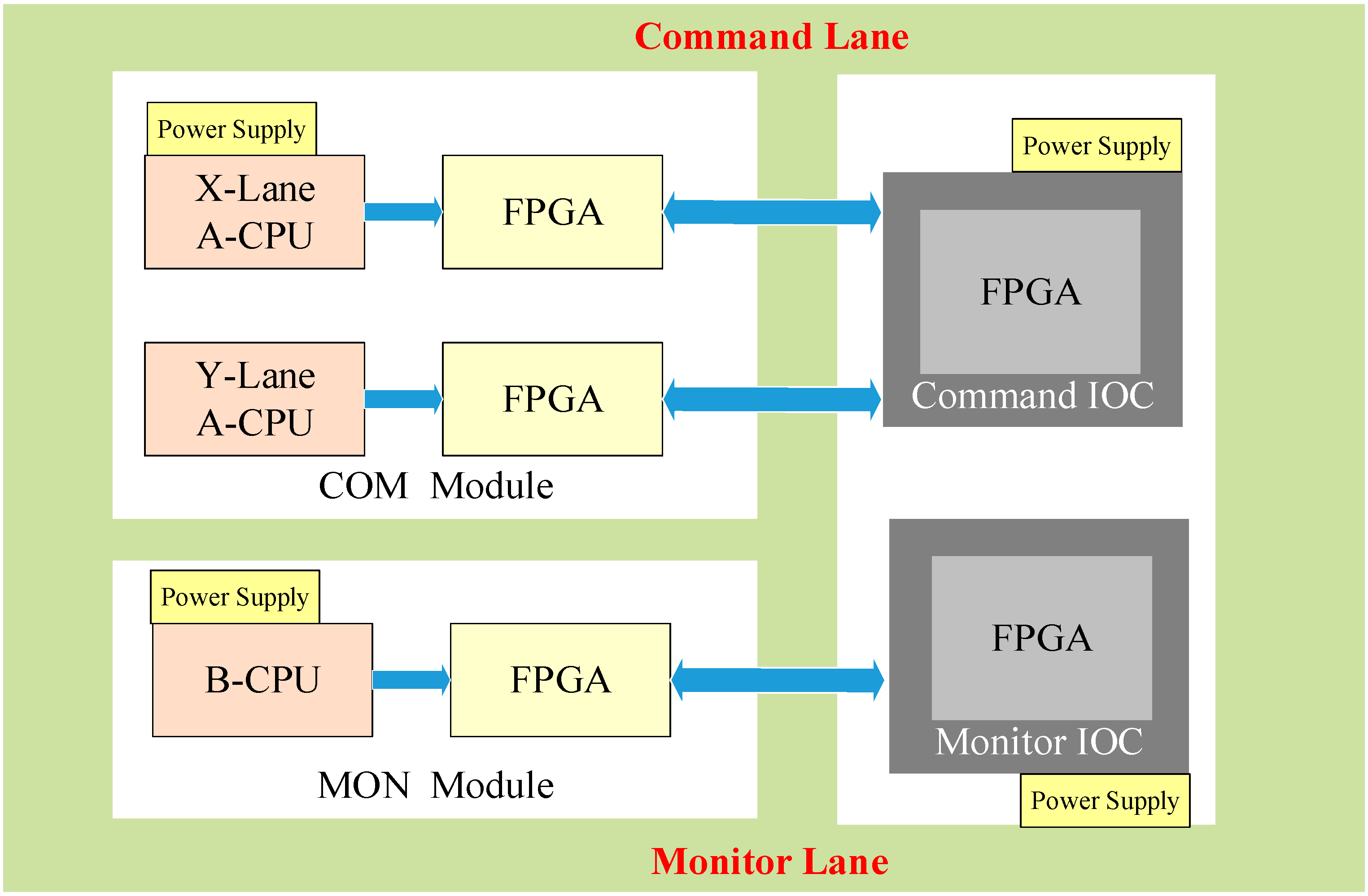
2.3. AADL Modeling: A Case Study of the Primary Flight Computer

In this section, a Primary Flight Computer (PFC) of an aircraft is selected as a study case to show the application of our AADL modeling method.

2.3.1. Description of the PFC

The PFC is a typical component that employs the redundant design in the flight control system. It receives control signals from the cockpit as input signals. PFC compromises three independent circuit boards: the command module, the monitor module, and the IO input/output module, as shown in Figure 1. Two lanes are present in the COM module, designated as the X-lane and Y-lane. Each lane is equipped with an identical type of CPU. Following processing by the CPU, the signals are transmitted to their respective FPGA for secondary processing. Simultaneously, a comparator is incorporated to compare the output signals from the X-lane and Y-lane, thereby preventing random failures In the MON module, a similar CPU is used to monitor the signals in the COM module. In the IOC module, the command IOC lane is mainly responsible for receiving external input signals, performing data processing, and sending the processed signals to the COM module CPU. The monitor IOC lane is mainly responsible for forwarding the processed signals to the MON module.

2.3.2. Nominal Model of the PFC

The nominal model of the PFC can be built by using the components given in Table 1. To provide a more detailed description of the internal structure, the “subsystem” components are chosen to model the command module (COM), the monitor module (MON), and the IO input/output module (IOC). By integrating the COM, MON, and IOC, the nominal model of the entire PFC is obtained, as illustrated in Figure 2.
Meanwhile, we can generate the code file of the PFC nominal model using an AADL tool such as Open Source AADL Tool Environment (OSATE).

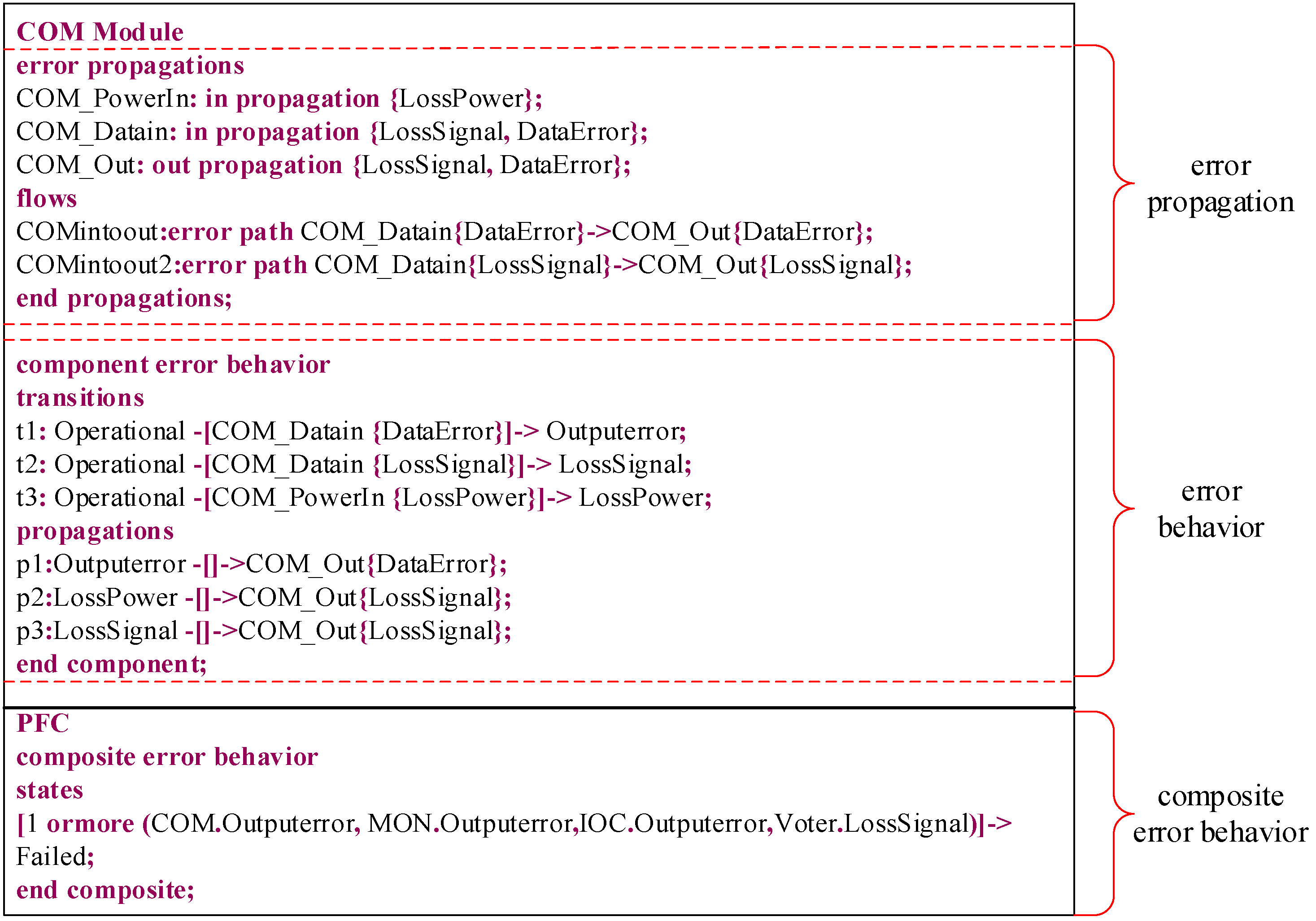
2.3.3. Extended Model of the PFC

In the extended model, the error annex library and the error model must be defined. Three error types, which are {LossPower}, {LossSignal}, and {DataError}, are defined in the extended model of the PFC. These errors propagate to other components through ports, thereby affecting other components. Error behavior is established for each component in the error annex library, including declarations of error events, states, and transitions. This process represents the state transitions of the components when an error event occurs.
The error model of PFC consists of three parts: component error propagation, component error behavior, and composite error behavior, as shown in Figure 3. Error propagation defines how an error propagates from or into a component. Component error behavior represents the state transitions and how the state propagates error. Composite error behavior analyzes the collective impact of multiple components on overall system behavior.
In Figure 3, the composite error behavior includes a Voter component (analogous to PFC.Comparator), which checks outputs from redundant lanes. If discrepancies exceed thresholds, the Voter triggers a DataError state. This component was omitted in earlier diagrams for simplicity but is integral to the error model.
By adding the code of the PFC error model to the code file of the PFC nominal model, we can build the extended model.

3. Identification of Independence Requirements Using Fault Propagation

The traditional approach to deriving common-mode independence requirements based on fault tree analysis is cumbersome, labor-intensive, and heavily dependent on analysts’ expertise. Consequently, a common-mode analysis method is proposed based on a fault propagation model.

3.1. Common-Mode Analysis Process

According to ARP4761A [5], the causes of CMF include engineering factors, usage factors, and environmental factors, which constitute the source of the common-mode checklist. The process of common-mode analysis is as follows [33].
Step 1: A general common-mode checklist is initially established, as shown in Table 2. Many elements should be considered, including concept and design, manufacturing, operation, environment, etc. [34].
Step 2: Redundant design characteristics are typically represented using the “AND” gate (including the voting gates) [35]. In CMA, events related to independence requirements can be determined by identifying each “AND” gate input event or minimum cut set in the fault tree.
Step 3: The independence requirements are analyzed based on the common-mode checklist. If they are not affected by common-mode failures, relevant architectural design and supporting documents need to be submitted; if affected, it is necessary to reduce or eliminate the common-mode sources by altering the architecture design or improving product manufacturing quality.

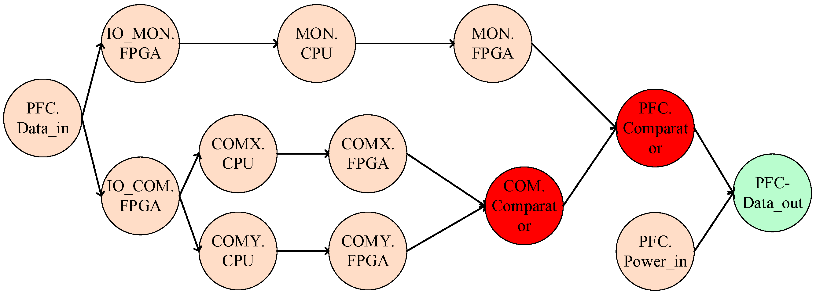
3.2. Fault Propagation Model Construction Based on the AADL Model

Based on the architectural and error annex information provided by the AADL model, a fault propagation model of the system can be established. Components susceptible to CMF can be identified by the fault propagation model. The following is a step-by-step procedure to build the fault propagation model.
Step 1: Component types are first identified. In the AADL model, faults propagate within or between components. By retrieving keywords such as “device”, “process”, and “system” that represent component types, all components and their interface information in the model can be determined and saved in a component array.
Step 2: Fault propagation information is declared in the Error Model Annex to describe how faults propagate within or between components. A matrix P is constructed to store this information. P is a zero matrix, where the dimension is the number of components. P can be shown below.
P = 0 p 12 p 1 n p 21 0 p 2 n p n 1 p n 2 0 ,
where the value of p i j is taken as 1 or 0. When p i j = 1 , it means fault propagates from component i to j .
Step 3: The state transition logic within composite error behaviors is then determined. In matrix P, if there are multiple elements “1” in a column, it indicates that a fault has propagated from multiple components to one component. CMF usually exists in redundant architectures represented by “and” logic. If the keyword “and” exists in the composite error behavior, it can be determined that the composite error behavior may cause CMF and is marked in the matrix P.
The fault propagation model is updated as the AADL model changes. It can ensure the consistency between two models.

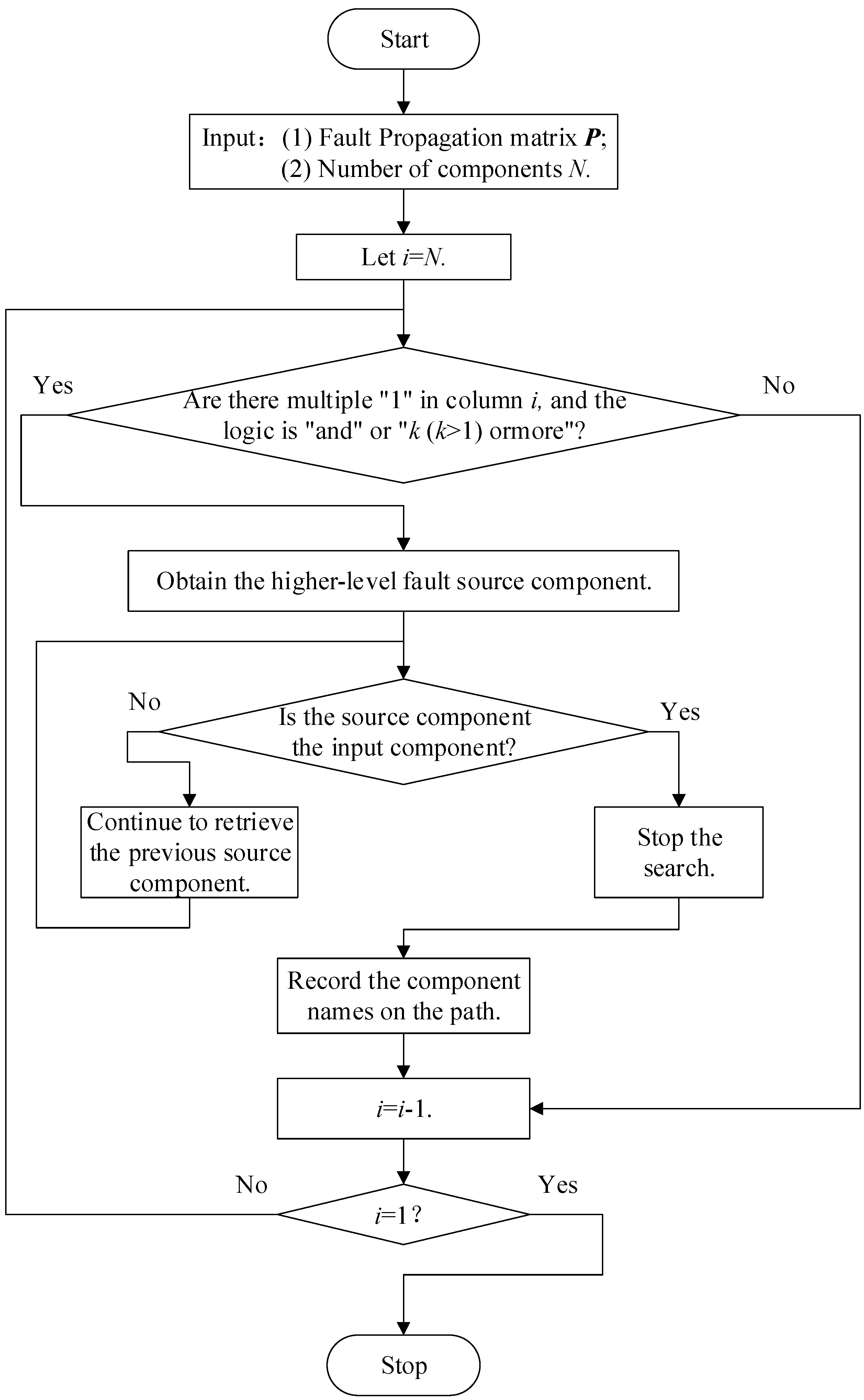
3.3. Common-Mode Independence Requirements Identification

In this section, the fault propagation paths are analyzed to identify components susceptible to CMF based on the fault propagation model. The method to obtain the fault propagation path is shown in Figure 4.
Step 1: CMA is performed based on the common-mode checklist. For ease of analysis, labels are assigned to components according to the checklist. In this step, we should consider the common-mode types and sources in the checklist to add the corresponding labels.
Step 2: In the fault propagation matrix P, the search begins from the last column, where the output component or interface is located. If there are multiple “1” values in the column and their composite error behavior logical is “and”, we record the component number of the column i .
Step 3: For each “AND” or “k (k > 1) ormore” logic component, its forward fault propagation path is determined. For example, the value of p j 1 i and p j 2 i in the column i is “1”. It means that only when fault propagates from component j 1 and j 2 , component i will continue to propagate the fault. Then we should retrieve the elements p k 1 j 1 and p k 2 j 2 in column j 1 and j 2 , where k 1 and k 2 are is the components that propagate faults from the previous level. We should repeat this process until the component is the initial input component. Then we record the component names corresponding to the matrix elements on these two propagation paths. The pseudo-code of Error propagation path determination is given in Algorithm 1.
Algorithm 1 The algorithm of Error propagation path determination
Extract Error propagation path: Extract_CP( )
INPUT: the error propagation model
OUTPUT: component path
1
  Extract_CP (error propagation model)
2
  component_paths = {}
3
  num_components = len(error_propagation_model)
4
  FOR i in range(num_components)
5
        IF sum(error_propagation_model[i]) > 1
6
              FOR j1 in range(num_components) and j2 in range(num_components)
7
                 IF error_propagation_model[i][j1] == 1 and error_propagation_model[i][j2] == 1
8
                    IF j1! = 0 and j2! = 0
9
                         path_ j1 = trace_fault_path(error_propagation_model, j1)
10
                       path_ j2 = trace_fault_path(error_propagation_model, j2)
11
                       component_paths[i] = {‘path_ j1’: path_ j1, ‘path_ j2’: path_ j2}
12
                      END IF
13
                    END IF
14
                 END FOR
15
     END IF
16
END FOR
17
END Extract_CP
Furthermore, each “AND” or “k (k > 1) ormore” logic component is identified by analyzing composite error behaviors in the AADL error annex. For example, if a component’s error behavior transitions depend on the simultaneous occurrence of errors from two upstream components (e.g., COMX.CPU and COMY.CPU), the composite behavior is tagged with an AND operator. This is programmatically detected using keyword searches (e.g., and in AADL error transitions) during model parsing.
Step 4: After determining the fault propagation path, possible CMF component combinations are identified. According to the two sets of components obtained in step 3, we should compare the elements in one set with those in the other set. If the components are the same type or have the same label, it is determined as a possible combination of CMF components and recorded. Then we return to step 3 until all “and” logical components are traversed.
Based on the identified component combinations, CMF risks are assessed using the common-mode checklist. If the components are affected by CMF, independence requirements should be proposed.

3.4. Independence Requirement Identification: A Case Study of the PFC

In this section, we also take the above-mentioned PFC as an example to show how to identify the common-mode independence requirements.

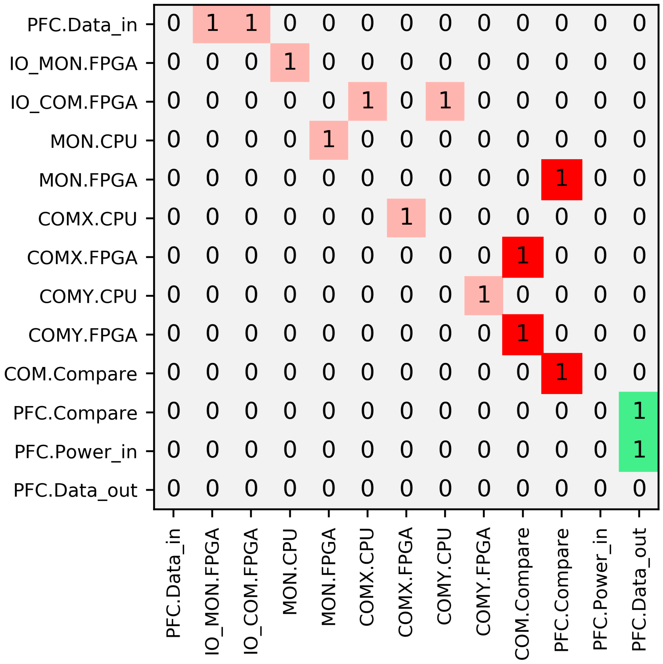
3.4.1. Fault Propagation Model of the PFC

There are 13 components or interfaces in PFC according to the AADL model. Figure 5 constructs a 13 × 13 fault propagation matrix P.
In fault propagation matrix P, the red cell indicates that the fault propagates by “and” logic. The green cell indicates that the fault propagates by “or” logic. According to Figure 5, there are multiple components propagating faults to components 10 (COM.Compare) and 11 (PFC.Compare) by “and” logic. So we need to analyze their forward fault propagation paths.

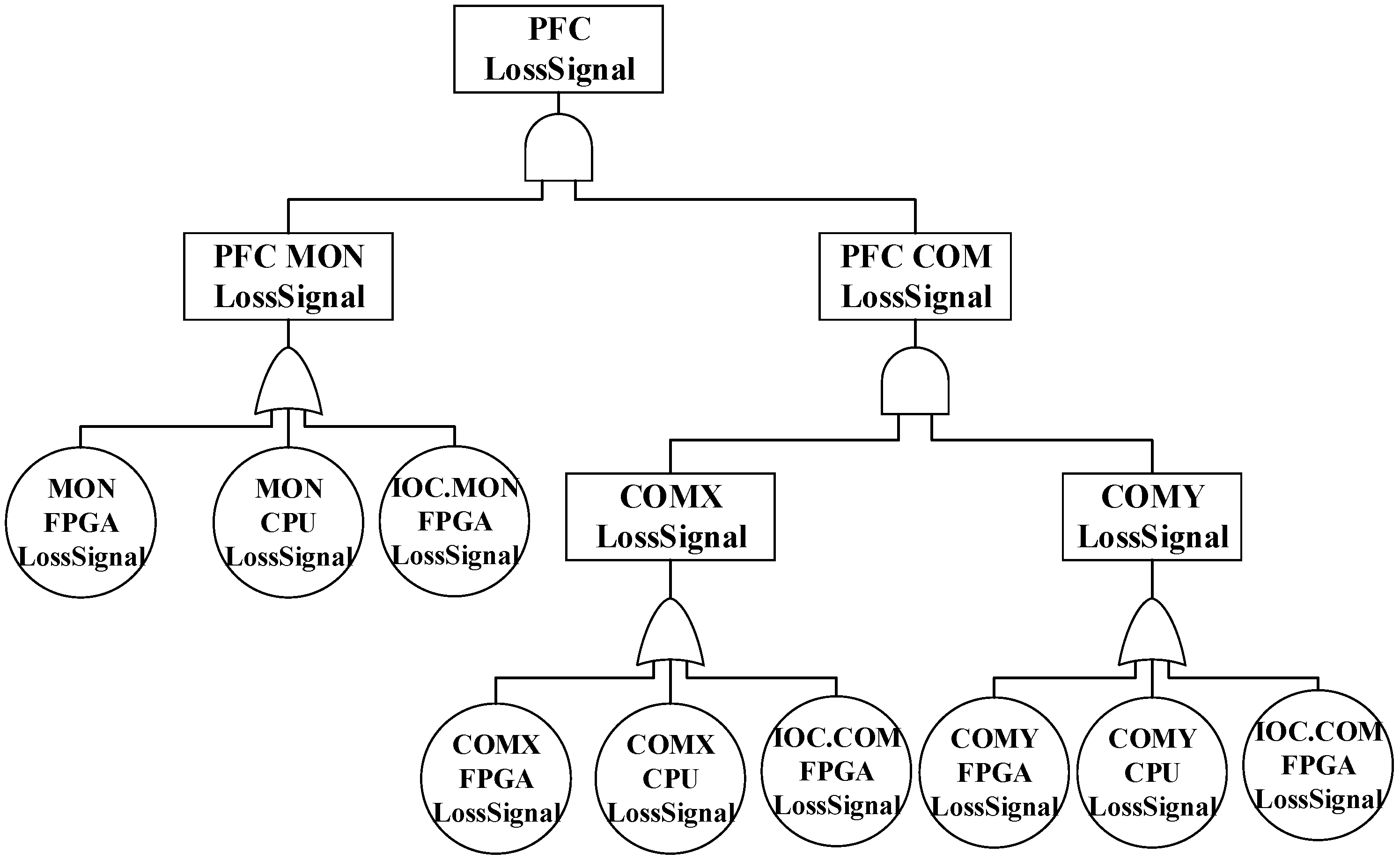
3.4.2. Common-Mode Independence Requirements Identification of the PFC

For more convenience analysis, we should add labels to the components according to the common-mode checklist. The labels added in PFC are shown in Table 3. For example, component “IO_COM.FPGA” has four labels. “IOC_Power” indicates that the FPGA is powered by the IOC module. “IOC” indicates that the FPGA is deployed and works in the IOC module. “FPGA” indicates that it is produced by FGPA manufacturers.
According to the fault propagation matrix, we analyze the “and” logic in it and obtain the fault propagation paths, as shown in Figure 6. There are three paths and two “and” logics in this fault propagation process. In fault propagation path, the red node indicates that the fault propagates by “and” logic. The green node indicates that the fault propagates by “or” logic.
The CMF components and independence requirements obtained from the comprehensive analysis of the PFC are shown in Table 4.

4. Discussion and Comparison Analysis

4.1. Common-Mode Independence Requirements Analysis

The common-mode independence requirements are analyzed by considering redundant components and functions.
For instance, in ID 1, {COMX.CPU} and {COMY.CPU} represent the processors used in the X and Y channels of the COM module, respectively. Simultaneous propagation of the {LossSignal} error by both processors may result in PFC signal loss. According to the common-mode checklist, these two CPUs are susceptible to CMF due to the same type of operating environment. Therefore, independence between these CPUs must be ensured. The requirement stating that “CPU in COM X-lane and Y-lane should be independent” is proposed.
In addition to redundant components, attention must also be given to the components of different types that perform the same function. In ID 6, {COMX.CPU} and {COMY.FPGA} represent the X-channel CPU and Y-channel FPGA in the COM module, respectively. Although differing in component type, both execute the function of processing PFC signals. According to the common-mode checklist, both components are located inside the COM module. Their power supply, data transmission, and working environment are susceptible to common-mode factors. Thus, the independence requirement stating that “CPU in X lane and FPGA in Y lane should be independent” is established.
Some component combinations may not necessarily result in CMF due to design architecture. In the 8th component combination, {COMX.FPGA} and {IOCMON.FPGA}, respectively, represent the FPGA of the X channel in the COM module and the MON in the IOC module. These two FPGAs perform different functions and have no connection interaction relationship. According to the common-mode checklist, their power supply, data transmission, and working environment are independent. So there is no need to propose independence requirements.

4.2. Comparison with FTA-Based Method

Reference [24] proposed a transformation rule from the AADL model to the fault tree model. The AADL modeling tool OSATE includes functionality for transforming AADL models into fault trees.
Traditional common-mode analysis is generally based on FTA [36]. It includes the analysis of the “AND” gate and minimum cut set of the fault tree.
The analysis of the “AND” gate requires analysts to observe the “AND” gates in the fault tree. The input events under each “AND” gate must be analyzed based on the common-mode checklist. However, the “AND” gate appears in different levels within the fault tree. This analysis method depends on the analyst’s understanding of the system and engineering experience. In complex fault trees, omissions are likely to occur.
The minimum cut set exhaustively lists all possible combinations that could result in the occurrence of the top event. The independence of the events within the minimum cut set must be analyzed. However, in complex redundant systems, a substantial number of minimum cut sets exist. The analysis workload is significant. And the events in the minimum cut set are basic events. The independence between intermediate-level events is not taken into account.
Taking “PFC LossSignal” as the top event, we can obtain the fault tree based on AADL, as shown in Figure 7.
In this fault tree, there are two “AND” gates. The input events of these gates should be independent. For example, the “AND” gate {PFC COMLossSignal} has two input events, {COMX LossSignal} and {COMY LossSignal}. It indicates that the X-lane and Y-lane in the COM module should be independent. For a more detailed analysis, the basic events under these two intermediate events should also be considered.
The analysis results of FTA are listed in Table 5. Comparing the FTA method and the method we proposed, the analysis results are the same. Our method avoids the cumbersome modeling process of fault trees and can be updated as the architecture changes.
Compared to Lanzani et al.’s work [17], our method avoids manual tagging of commonalities by leveraging AADL’s inherent error propagation semantics, reducing subjectivity. Furthermore, our toolchain supports iterative updates, whereas their approach requires re-tagging after design changes.

5. Conclusions

This study carries out CMA and identifies the common-mode independence requirements based on the AADL model. The main contributions of this study are as follows:
  • AADL is used to establish nominal and extended models of redundant systems. CMA is conducted based on these models, ensuring consistency between the aircraft analysis and the design models.
  • A fault propagation model is established based on the AADL model. It can identify factors that may cause aircraft system CMF and propose independence requirements. The analysis results can be dynamically updated in response to architecture modification.
  • The effectiveness of the proposed method is verified by comparing the CMA method based on the fault propagation model with the traditional FTA method. The proposed method can avoid the cumbersome process of constructing fault trees in traditional CMA.
This study presents the following key innovations:
  • AADL-based automation for independence requirements: We introduce a novel, automated method to derive common-mode independence requirements directly from AADL models. By constructing a fault propagation model and analyzing its logic (e.g., “AND” gates), the method systematically identifies potential CMF component combinations, significantly reducing manual effort and subjectivity compared to traditional FTA-based CMA.
  • Ensured consistency and dynamic update capability: The approach maintains consistency between the AADL design model and safety analysis (fault propagation model, requirements). Crucially, both the model and derived requirements can be dynamically updated as the architecture evolves, enabling efficient iterative design and assessment.
The limitations of our work include reliance on AADL’s error annex for fault modeling, which may not capture all physical interactions. Future work will integrate SysML for multi-physics analysis and extend the method to probabilistic CMF scenarios.

Author Contributions

Conceptualization, Z.L.; Methodology, Z.L.; Software, Y.Z.; Validation, H.R. and F.Q.; Formal analysis, H.R.; Data curation, H.R. and Y.Z.; Writing—original draft, F.Q. and Z.L.; Writing—review & editing, F.Q.; Visualization, Y.Z.; Supervision, X.W.; Project administration, X.W.; Funding acquisition, X.W. All authors have read and agreed to the published version of the manuscript.

Funding

This work was supported by the Fundamental Research Funds for the Central Universities of China under Grant NG2023003, and the National Key Research and Development Program of China under Grant 2023YFB4302403.

Data Availability Statement

The original contributions presented in the study are included in the article, further inquiries can be directed to the corresponding authors.

Conflicts of Interest

The authors declare no conflict of interest.

Abbreviations

The following abbreviations are used in this manuscript:
CMFCommon-mode failures
CMACommon-mode analysis
FTAFault tree analysis
MBSAModel-based safety analysis
AADLArchitecture analysis and design language
PFCPrimary flight computer
CPUCentral processing unit
FPGAField programmable gate array
OSATEOpen source AADL tool environment
IOCInput and Output Controller
COMCommand Module
MONMonitor Module

References

  1. ARP4761A; Guidelines for Conducting the Safety Assessment Process on Civil Aircraft, Systems, and Equipment. SAE International: Warrendale, PA, USA, 2023.
  2. Peng, C.; Sun, Y.C.; Guo, Y.Y. Assessment of safety risk in airline operations based on constant-sum game. Proc. Inst. Mech. Eng. Part G J. Aerosp. Eng. 2024, 238, 157–168. [Google Scholar] [CrossRef]
  3. Huang, M.Y.; Jie, Y.W.; Song, Z.T. Common mode airworthiness requirements and certification considerations for fly-by-wire. Civ. Aircr. Des. Res. 2023, 2, 1–7. [Google Scholar]
  4. Hana, M.; Dominique, B.; Etienne, B. A benchmark of incremental model transformation tools based on an industrial case study with AADL. Softw. Syst. Model. 2022, 22, 175–201. [Google Scholar]
  5. Zhang, X.S.; Leng, K.; Luo, S.M.; Zeng, Q.H. Research on the safety analysis of multi-purpose civil engine. Qual. Reliab. 2023, 5, 35–40. [Google Scholar]
  6. ARP4754A; Guidelines for Development of Civil Aircraft and Systems. SAE International: Warrendale, PA, USA, 2010.
  7. Gao, S.; Wang, J.T.; Zhang, J. Reliability analysis of a redundant series system with common cause failures and delayed vacation. Reliab. Eng. Syst. Saf. 2023, 239, 109467. [Google Scholar] [CrossRef]
  8. Sun, M.; Gautham, S.; Ge, Q. Defining and characterizing model-based safety assessment: A review. Saf. Sci. 2024, 172, 106425. [Google Scholar] [CrossRef]
  9. Chen, L.; Jiao, J.; Zhao, T.D. Review for model-based safety analysis of complex safety-critical system. Syst. Eng. Electron. 2017, 39, 1287–1291. [Google Scholar]
  10. Rauzy, A. Mode automata and their compilation into fault trees. Reliab. Eng. Syst. Saf. 2002, 78, 1–12. [Google Scholar] [CrossRef]
  11. Joshi, A.; Miller, S.P.; Whalen, M.; Heimdahl, M.P.E. A proposal for model-based safety analysis. In Proceedings of the 24th Digital Avionics Systems Conference, Washington, DC, USA, 30 October–3 November 2005; Volume 2, p. 13. [Google Scholar]
  12. Akerlund, O.; Bieber, P.; Boede, E.; Bozzano, M.; Bretschneider, M.; Castel, C.; Cavallo, A.; Cifaldi, M.; Gauthier, J.; Griffault, A.; et al. ISAAC, a framework for integrated safety analysis of functional, geometrical and human aspects. In Proceedings of the Embedded Real Time Software and Systems Conference, Toulouse, France, 25–27 January 2006. [Google Scholar]
  13. Lanzani, L.; Uliano, L.; Scattolini, R. Integration of commonalities in the paradigm of model-based safety analysis in aerospace. In Proceedings of the 17th International Conference on Probabilistic Safety Assessment and Management and Asian Symposium on Risk Assessment and Management, Kyoto, Japan, 7–11 October 2024. [Google Scholar]
  14. Magdalena, P.; Wojciech, S. Assessment of the Potential of Electric Propulsion for General Aviation Using Model-Based System Engineering (MBSE) Methodology. Aerospace. 2022, 9, 74. [Google Scholar]
  15. Qi, J.; Hu, J.; Gu, Q.F. Class flattening method for Altarica 3.0 model. Comput. Sci. 2021, 48, 51–59. [Google Scholar]
  16. Arnold, A.; Point, G.; Griffault, A.; Rauzy, A. The AltaRica formalism for describing concurrent systems. Fundam. Inform. 1999, 40, 109–124. [Google Scholar] [CrossRef]
  17. Feiler, P.; Gluch, D.; Hudak, J. The Architecture Analysis & Design Language (AADL): An Introduction; Carnegie Mellon University, Software Engineering Institute’s Digital Library, Software Engineering Institute: Pittsburgh, PA, USA, 2006. [Google Scholar]
  18. AS5506/1; SAE Architecture Analysis and Design Language (AADL) Annex Volume 1: Annex E: Error Model Annex. SAE International Technical Standard: Warrendale, PA, USA, 2006.
  19. Jiang, Z.Y.; Zhao, T.D.; Wang, S.H. New Model-Based Analysis Method with Multiple Constraints for Integrated Modular Avionics Dynamic Reconfiguration Process. Processes 2020, 8, 574. [Google Scholar] [CrossRef]
  20. Ling, S.X.; Yang, Z.B.; Guo, P.; Zhou, Y. An approach for IMA software code generation on domestic airborne operating system. Aeronaut. Comput. Tech. 2024, 54, 84–88. [Google Scholar]
  21. Hou, Z.G.; Xiong, M.L.; Wang, H.W. Civil aviation safety risk intelligent early warning model based on text mining and multi-model fusion. Proc. Inst. Mech. Eng. Part G J. Aerosp. Eng. 2023, 237, 2402–2427. [Google Scholar] [CrossRef]
  22. Pop, P.; Zarrin, B.; Barzegaran, M. The FORA fog computing platform for industrial IoT. Inf. Syst. 2021, 98, 101727. [Google Scholar] [CrossRef]
  23. Sannes, P.S.; Apvrille, L.; Vingerhoeds, R. Checking SysML models against safety and security properties. J. Aerosp. Inf. Syst. 2021, 18, 906–918. [Google Scholar]
  24. Li, D.M.; Li, J.; Lin, H.F. Reliability Analysis method of Embedded System AADL Model Based on Fault Tree Analysis. Comput. Sci. 2017, 44, 182–188. [Google Scholar]
  25. Maruf, A.M.; Azim, A. Requirements-preserving design automation for multiprocessor embedded system applications. J. Ambient Intell. Humaniz. Comput. 2020, 12, 821–833. [Google Scholar] [CrossRef]
  26. Liu, L.; Lei, L.; Zhao, W. A Safety Evaluation Method of IMA Dynamic Reconfiguration Process Based on CPN. J. Phys. Conf. Ser. 2020, 1646, 012053. [Google Scholar] [CrossRef]
  27. Belt, J.; Hatcliff, J.; Shackleton, J. Model-driven development for the seL4 microkernel using the HAMR framework. J. Syst. Archit. 2023, 134, 102789. [Google Scholar] [CrossRef]
  28. Li, Z.; Cao, Z.N.; Fang, F.J. A Modeling and Verification Method of Cyber-Physical Systems Based on AADL and Process Algebra. Int. J. Softw. Eng. Knowl. Eng. 2024, 34, 49–89. [Google Scholar] [CrossRef]
  29. Hamdane, M.E.; Harous, S.; Kerkouche, E. Improving consistency of AADL models: A composition approach. Syst. Eng. 2023, 26, 257–270. [Google Scholar] [CrossRef]
  30. Lu, Y.; Qin, S.D.; Guo, P. Hardware-software Integrated Reliability Modeling and Analysis Using AADL. J. Softw. 2022, 33, 2995–3014. [Google Scholar]
  31. Yang, H.Y.; Sun, Y.C. A combination method for integrated modular avionics safety analysis. Aircr. Eng. Aerosp. Technol. 2023, 95, 345–357. [Google Scholar] [CrossRef]
  32. Zhang, R.; Geng, L.; Liu, W. Research on static fault tree analysis method for inerting system safety based on random number generation. Aircr. Eng. Aerosp. Technol. 2023, 95, 649–657. [Google Scholar] [CrossRef]
  33. Liu, W.; Guo, Q.; Wang, M. Research on Airborne Electronic Equipment Common Mode Analysis Method. Aeronaut. Comput. Tech. 2022, 52, 126–129. [Google Scholar]
  34. Luo, J.G. Quantitative safety analysis of train control system considering common cause failure. Control Inf. Technol. 2024, 1, 116–120. [Google Scholar]
  35. Luo, J.W.; Ge, J.Z.; Chen, K.P. Review of reliability assessment methods for complex systems. Electron. Prod. Reliab. Environ. Test. 2024, 41, 122–130. [Google Scholar]
  36. Tao, J.; Ye, Y.; Jiang, Z.Q.; Tang, B.; Liu, Q. Research on reliability model of power synchronous network based on Beidou system. Electron. Des. Eng. 2024, 32, 150–154. [Google Scholar]
Figure 1. PFC internal structure.
Aerospace 12 00603 g001
Figure 2. AADL nominal model of the PFC.
Aerospace 12 00603 g002
Figure 3. The code of the PFC error model.
Aerospace 12 00603 g003
Figure 4. Fault propagation path retrieval process.
Aerospace 12 00603 g004
Figure 5. Fault propagation matrix.
Aerospace 12 00603 g005
Figure 6. Fault propagation path.
Aerospace 12 00603 g006
Figure 7. PFC {LossSignal} fault tree.
Aerospace 12 00603 g007
Table 1. AADL component meaning.
CategoryComponentDetailed Explanations
SoftwareDataDifferent types of data
ThreadSchedulable units for parallel execution
ProcessVirtual processor for scheduling and executing threads
HardwareProcessorScheduling and executing threads
MemoryStore code and data
BusConnect processors, memory, and devices
DeviceComponents such as sensors and actuators that represent external interfaces
SystemAbstractRepresent any other component
SystemIntegrate software, hardware, and other components
Table 2. Common-mode checklist.
Common-Mode TypesCommon-Mode Sub-TypesCommon-Mode Sources
Concept and DesignDesign ArchitectureElectrical power, hydraulic, ventilation, etc.
Technology, Materials, EquipmentSize, hardware, software, material, etc.
ManufacturingManufacturerCommon manufacturer, procedure, etc.
OperationStaff, proceduresCommon staff, same procedure
EnvironmentElectrical and radiationElectromagnetic, radiation, etc.
Mechanical and thermalTemperature, grit, vibration, etc.
Table 3. Component labels.
Component
Name
Design ArchitectureTechnology, Materials, EquipmentManufacturer
IO_COM.
FPGA
IOC_PowerIOCFPGA manufacturer
IO_MON.
FPGA
IOC_PowerIOCFPGA manufacturer
COMX.
CPU
COM_PowerCOMCPU_A manufacturer
COMX.
FPGA
COM_PowerCOMFPGA manufacturer
COMY.
CPU
COM_PowerCOMCPU_A manufacturer
COMY.
FPGA
COM_PowerCOMFPGA manufacturer
COM.
Comparator
COM_PowerCOMComparator manufacturer
MON.
CPU
MON_PowerMONCPU_B manufacturer
MON.
FPGA
MON_PowerMONFPGA manufacturer
PFC.
Comparator
PFC_PowerPFCComparator manufacturer
Table 4. Common-mode failure component and independence requirement.
CodeComponent PairIndependence Requirement Description
1COMX.
CPU
COMY.
CPU
CPU in COM X-lane and Y-lane should be independent
2COMX.
CPU
MON.
CPU
CPU in COM and MON module should be independent
3COMX.
FPGA
COMY.
FPGA
FPGA in COM X-lane and Y-lane should be independent
4COMX.
FPGA
MON.
FPGA
FPGA in COM and MON module should be independent
5IO_COM.
FPGA
IO_MON.
FPGA
FPGA in IOC module COM and MON should be independent
6COMX.
CPU
COMY.
FPGA
CPU in X lane and FPGA in Y lane should be independent
7COMY.
CPU
COMX.
FPGA
CPU in Y lane and FPGA in X lane should be independent
8COMX.
FPGA
IO_MON.
FPGA
CPU in COM and IOC module should be independent
9COMY.
FPGA
IO_MON.
FPGA
N/A
10MON.
FPGA
IO_MON.
FPGA
N/A
Table 5. Common-mode independence requirement (FTA).
IDIndependence Requirement
1CPU in COM X-lane and Y-lane should be independent
2CPU in COM and MON module should be independent
3FPGA in COM X-lane and Y-lane should be independent
4CPU in COM and IOC module should be independent
5FPGA in COM and MON module should be independent
6FPGA in IOC module COM and MON should be independent
7CPU in X lane and FPGA in Y lane should be independent
8CPU in Y lane and FPGA in X lane should be independent
Disclaimer/Publisher’s Note: The statements, opinions and data contained in all publications are solely those of the individual author(s) and contributor(s) and not of MDPI and/or the editor(s). MDPI and/or the editor(s) disclaim responsibility for any injury to people or property resulting from any ideas, methods, instructions or products referred to in the content.

