Article

Manufacturing Process of Stealth Unmanned Aerial Vehicle Exhaust Nozzles Based on Carbon Fiber-Reinforced Silicon Carbide Matrix Composites

1
3rd R&D Institute (METC), Agency for Defense Development, P.O. Box 35, Daejeon 34186, Republic of Korea
2
2nd R&D Institute, Agency for Defense Development, P.O. Box 35, Daejeon 34186, Republic of Korea
3
1st R&D Institute, Agency for Defense Development, P.O. Box 35, Daejeon 34186, Republic of Korea
*
Author to whom correspondence should be addressed.
Aerospace 2025, 12(7), 600; https://doi.org/10.3390/aerospace12070600
Submission received: 1 June 2025 / Revised: 25 June 2025 / Accepted: 29 June 2025 / Published: 1 July 2025
(This article belongs to the Section Aeronautics)

Abstract

This study presents the development of a manufacturing process for a double-serpentine (DS) exhaust nozzle for unmanned aerial vehicles (UAVs) based on carbon fiber-reinforced silicon carbide matrix composites (C/SiCs). The DS nozzle is designed to reduce infrared emissions from hot exhaust plumes, a critical factor in enhancing stealth performance during UAV operations. The proposed nozzle structure was fabricated using a multilayer configuration consisting of an inner C/SiC layer for thermal and oxidation resistance, a silica–phenolic insulation layer to suppress heat transfer, and an outer carbon fiber-reinforced polymer matrix composite (CFRPMC) for mechanical reinforcement. The C/SiC layer was produced by liquid silicon infiltration, preceded by pyrolysis and densification of a phenolic-based CFRPMC preform. The final nozzle was assembled through precision machining and bonding of segmented components, followed by lamination of the insulation and outer layers. Mechanical and thermal property tests confirmed the structural integrity and performance under high-temperature conditions. Additionally, oxidation and ablation tests demonstrated the excellent durability of the developed C/SiC. The results indicate that the developed process is suitable for producing large-scale, complex-shaped, high-temperature composite structures for stealth UAV applications.

1. Introduction

Recent conflicts have witnessed a sharp rise in the deployment of unmanned aerial vehicles (UAVs), to the extent that modern warfare is often characterized as “drone warfare.” In the early stages of combat, UAVs provided a decisive advantage owing to their large numbers and operational flexibility. However, as engagements prolonged and air-defense systems were established around strategic targets, UAV attrition rates increased considerably, resulting in substantial losses of military capability. To mitigate these losses, technologically advanced nations are now developing stealth-capable UAVs and fighter aircraft, with a strong emphasis on enhancing survivability through the integration of low-observable technologies [1,2,3,4,5].
Conventionally, metal- and alloy-based materials have been used for UAV engine exhaust nozzles because of their ease of fabrication and well-established mechanical stability. However, as demands for extended flight durations grow and air defense systems evolve, there is an increasing need for materials that are lighter, more heat-resistant, and less detectable. This shift has led to extensive research into advanced composites capable of withstanding extreme environments [6,7,8,9]. In aerospace and defense applications, structural materials must endure temperatures ranging from several hundred to several thousand degrees Celsius, requirements considerably exceeding those of civilian applications. Conventional polymer matrix composites (PMCs) fail under such conditions owing to their limited thermal stability. Carbon fiber-reinforced carbon matrix composites (C/Cs) have therefore been widely used in missile and guided-weapon nozzles due to their excellent wear resistance and structural stability at temperatures up to 3000 °C in inert environments [10]. However, C/Cs oxidize rapidly in atmospheric conditions above 450 °C, leading to severe property degradation [11]. Consequently, they are unsuitable for long-duration applications in oxidizing environments, such as reusable UAV engine nozzles. Although ceramic or nitride coatings can enhance oxidation resistance, mismatches in thermal expansion coefficients between the coating and C/C substrate often induce cracking, limiting their usefulness.
Ceramic matrix composites, particularly silicon carbide fiber-reinforced silicon carbide matrix composites (SiC/SiCs), have emerged as promising candidates for high-temperature applications [12,13] because of their superior oxidation resistance and thermal-shock stability at temperatures up to 1000 °C. However, their extremely high cost and export restrictions—as they are classified as strategic materials—hinder widespread adoption [14]. As an alternative, carbon fiber-reinforced silicon carbide matrix composites (C/SiCs) offer improved oxidation resistance over C/Cs while maintaining more favorable cost-effectiveness and mechanical performance compared to SiC/SiCs [15,16,17,18]. The intrinsic properties of silicon carbide, including high oxidation resistance, thermal stability, and creep resistance, enable C/SiCs to protect carbon fibers from oxidation and preserve structural integrity in high-temperature oxidative environments. Nevertheless, challenges such as lower oxidation resistance relative to SiC/SiCs, reduced maximum service temperature compared to C/Cs, and weakened interfacial bonding due to thermal-expansion mismatches between carbon and silicon carbide remain. Figure 1 shows the estimated service duration of representative high-temperature composite materials as a function of temperature, providing a comparative overview of their thermal-endurance characteristics.
Composite-based exhaust nozzles for low-observable UAVs must withstand extreme conditions of high temperatures and high-pressure exhaust gases. While the intrinsic heat and ablation resistance of the base material are essential, minimizing the infrared (IR) signature generated by engine exhaust is equally critical for survivability against IR-tracking systems. Metallic materials, owing to their high thermal conductivity and density, are less effective for IR suppression and lightweight design. Therefore, recent trends in military aviation favor composite materials for exhaust nozzles [21,25]. Composites can be engineered into multilayer architectures that integrate different functionalities within a single component. For instance, the inner layer can be optimized for high-temperature resistance using C/SiCs, while the outer layer can be optimized for mechanical reinforcement and thermal insulation using lightweight CFRPMCs. A thermally insulating middle layer can be inserted to inhibit heat transfer to the outer structure, thereby maintaining a lower external surface temperature and reducing IR emissions. Additionally, optimizing material configuration and nozzle geometry plays a crucial role in minimizing the IR signature by lowering the maximum temperature of the aft-deck and external surface.
This study primarily develops a double-serpentine (DS), high-temperature-resistant composite nozzle designed to suppress and shield IR signatures generated by UAV propulsion exhaust plumes. The intended operational environment involves prolonged missions, with exhaust temperatures reaching up to 550 °C. Given the high-speed, high-pressure flow under low-oxygen conditions and the absence of ultra-high-temperature exposures exceeding 1000 °C, a C/SiC-based DS nozzle is selected for its superior oxidation resistance compared with C/Cs and its cost advantage over SiC/SiCs. The nozzle is fabricated using liquid silicon infiltration (LSI), where molten silicon infiltrates a pyrolyzed porous C/C preform and reacts with the carbon matrix to form an in situ SiC matrix [18,26].
However, due to the intrinsic brittleness of the SiC matrix, thermal deformation and cracking frequently occur during processing, necessitating careful control of the thermal history and optimization of each manufacturing step. These challenges become more critical when scaling up to large, complex-geometry DS nozzles, in contrast to small-scale nozzles or divert and attitude control systems used in missiles. Therefore, developing a robust, geometry-adaptive process is essential to maintaining structural integrity during high-temperature treatment. The developed nozzle features a large-scale structure exceeding 1.6 m in length and employs a multilayer design. The innermost layer, directly exposed to high-temperature, high-pressure exhaust gases, consists of C/SiC for enhanced erosion and oxidation resistance. The outermost layer comprises CFRPMC to reinforce the mechanical strength of the large nozzle structure. A silica fiber-based thermal insulation composite is positioned in the middle layer to minimize heat conduction, thereby preserving structural stability while contributing to overall IR emission reduction.

2. Development of the Manufacturing Process for High-Temperature, Low-Observable Composite Engine Exhaust Nozzles for UAVs

Although the fabrication steps used in this study are based on established industrial processes—such as autoclave molding, polymer infiltration and pyrolysis, and LSI—the uniqueness of this study lies in the process adaptations and optimizations developed to enable the manufacturing of a large, geometrically complex, multilayered DS nozzle. This section outlines the fabrication strategy, which includes segmentation based on internal flow profiles, optimized placement of preforms, and precise control of the thermal history to prevent deformation and cracking during high-temperature processes. These elements are crucial for large-scale ceramic matrix composites and represent original contributions beyond conventional fabrication methods.

2.1. Fabrication of the PMC Preform

To produce C/SiCs via the LSI method, it is essential to first fabricate a PMC preform prior to the densification stage. In this study, the preform was made from CFRPMCs prepared by laminating prepregs composed of phenolic resin-impregnated carbon fiber fabrics. The laminate was then cured in an autoclave to achieve the desired geometry and initial mechanical integrity.

2.1.1. Materials

Prepregs were used as the intermediate material for CFRPMC fabrication. Two types of carbon fibers were considered: polyacrylonitrile (PAN)-based and rayon-based. Rayon-based fibers exhibit superior thermal shrinkage stability and have conventionally been used in missile and rocket nozzle applications. Meanwhile, PAN-based fibers are favored for their high mechanical strength, cost-effectiveness, and reliable supply. However, rayon-based fibers proved more susceptible to reaction with molten silicon during the LSI process, leading to fiber degradation and reduced mechanical performance; they also exhibited poorer matrix impregnation. Consequently, PAN-based carbon fiber (H2550, Hyosung Advanced Materials Co., Ltd., Jeonju, Republic of Korea), a grade similar to the Toray T-700, was selected for the final fabrication. The fundamental properties of H2550 are summarized in Table 1, based on data from the official technical data sheet provided by the manufacturer.
The polymer matrix of the prepreg was based on phenolic resin, chosen to maximize residual carbon yield after pyrolysis for effective reaction with silicon during LSI. Phenolic resins combine excellent mechanical strength, dimensional stability, processability, and chemical resistance, and they retain rigidity at elevated temperatures. Above 300 °C, phenolic resin decomposes to form coke-like carbon residue, which both protects the carbon fibers during LSI and supplies carbon for in situ SiC formation [27,28]. The prepreg used was based on SC-1008 phenolic resin; its key physical properties are listed in Table 2.

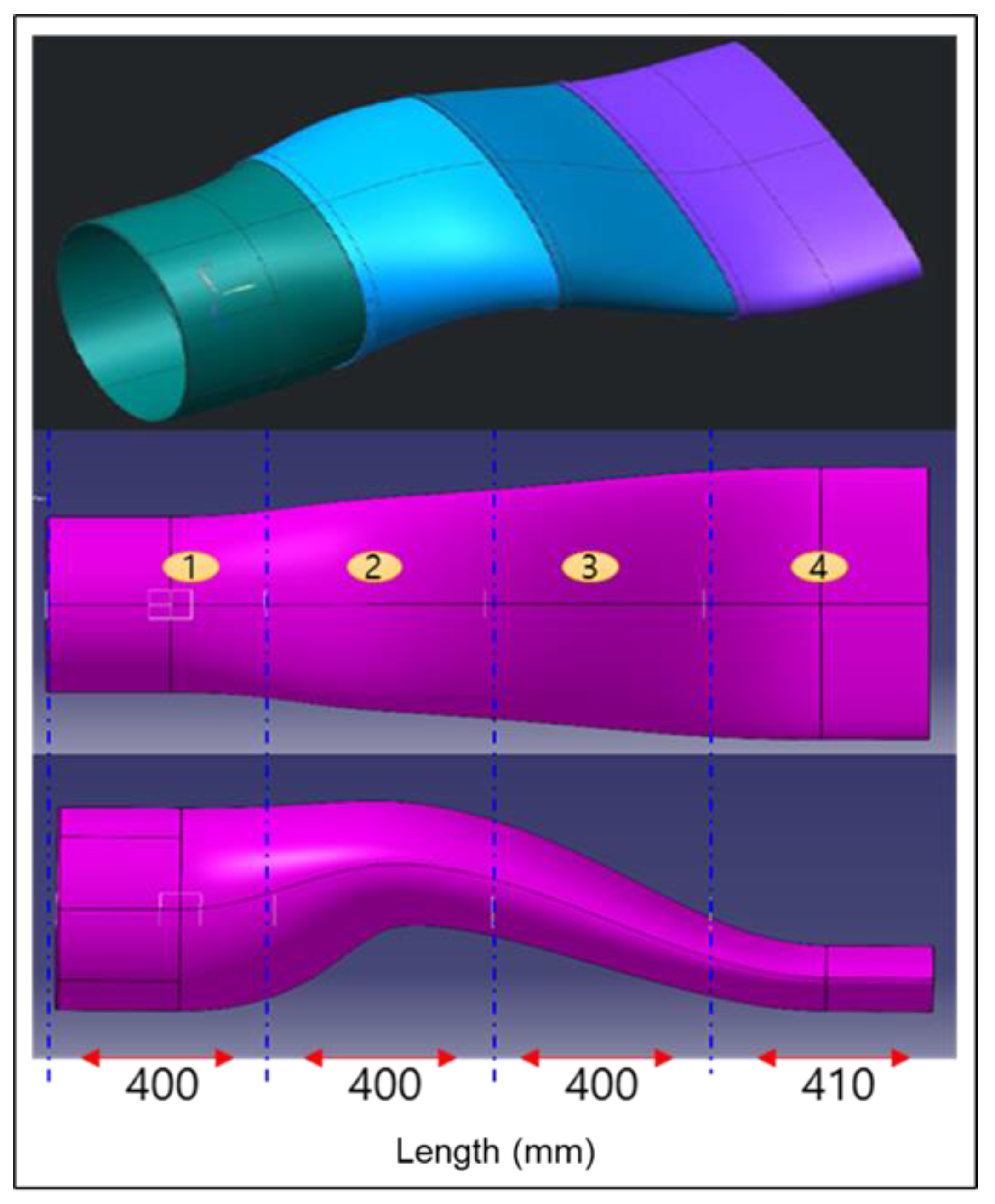
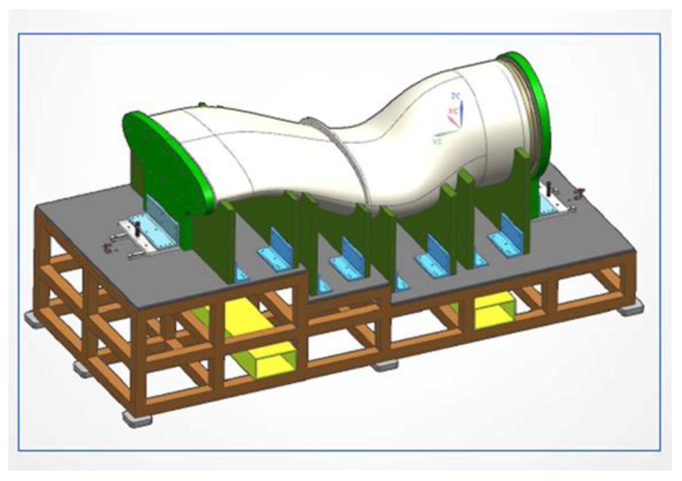
2.1.2. Preform Design According to Nozzle Geometry

Figure 2, Figure 3 and Figure 4 show the conceptual design, external geometry, and precise dimensional configuration of the exhaust nozzle for a low-observable UAV engine. Because the UAV platform and exhaust system geometry were fixed to meet thrust requirements, airframe integration, and IR-signature reduction, the CFRPMC preform needed to match the finalized design precisely. During pyrolysis and the subsequent LSI process, the preform undergoes dimensional changes due to thermal expansion and shrinkage. To prevent deformation and cracking from residual stresses during cooling, the inner diameter at the engine interface was designed to be approximately 2–3% larger than the final dimension [29]. At the elliptical aft end, where the nozzle mates with the aft-deck, the radius of curvature increased by 3–5% in regions of tight curvature, while areas of gentler curvature remained unchanged.
Given the size constraints in the LSI chamber, the nozzle was segmented into four parts. Segmentation locations were chosen based on computational fluid dynamics (CFD) simulations of internal temperature, pressure, and flow velocity distributions (Figure 5 and Figure 6). These results indicate that temperature, pressure, and flow velocity distributions within the nozzle vary considerably along its length. Therefore, a segmentation scheme was established based on geometric considerations and by avoiding regions subjected to extreme thermal and mechanical loads.
CFD simulations were conducted to design the exhaust nozzle and analyze the internal flow field. A stagnation inlet boundary condition was applied at the nozzle entrance, and no-slip wall conditions were imposed on the nozzle wall surfaces. For the downstream plume region, a pressure outlet boundary condition corresponding to the standard atmospheric pressure was used. The inlet included both bypass and core streams, with boundary conditions corresponding to the maximum take-off thrust of the turbofan engine considered in this study. The surrounding ambient region was also assigned a pressure boundary condition corresponding to the atmospheric pressure. Approximately two million mesh elements were used in the simulation, with refined meshing near the walls to ensure that the non-dimensional wall distance (y+) remained below 1.0, enabling accurate resolution of boundary layers.
Detailed segmentation is shown in Figure 7, with parts #1–#4 numbered in the exhaust-flow direction.

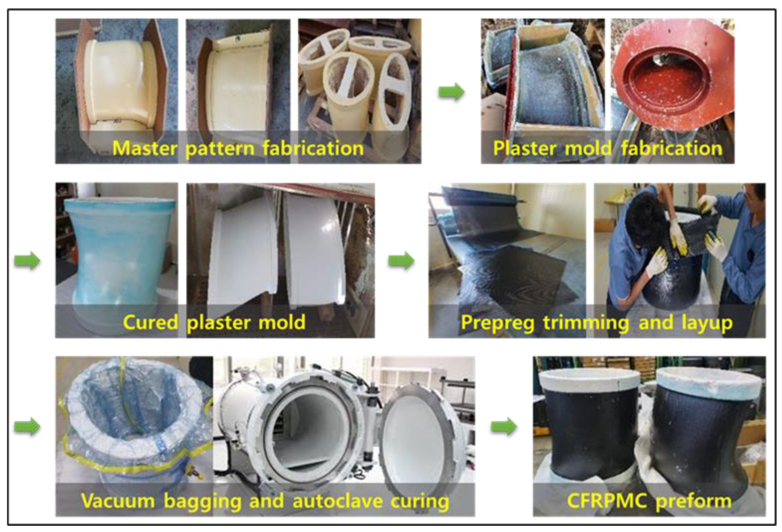
2.1.3. CFRPMC Preform Fabrication

In the initial trial, prepregs were laminated into nozzle shape using a removable metallic mold. After forming, the mold was stripped, and the preform was pyrolyzed; however, without structural support during high-temperature treatment, significant deformation occurred. To resolve this, a new mold was cast from plaster reinforced with chopped glass fiber strands; this mold withstood pyrolysis and was not removed. Carbon fiber/phenolic prepregs were then hand-laid to a thickness of approximately 4 mm on the mold’s surface.
The lay-up orientation varied according to segment geometry: for the simple cylindrical part #1, 0°/90° fabric orientation was used; for the curved parts #2 and #3, ±45° orientation enhanced flexibility; and for the flat, elliptical part #4, alternating 0°/90° and ±45° layers balanced strength and shrinkage. To facilitate gas escape during pyrolysis and improve silicon infiltration during LSI, a thin layer of carbon black powder was applied between each prepreg layer. The prepregs were cut into uniform patches and overlapped (rather than continuously wound) to reduce residual stress and control gas release. The use of a patch-type lay-up was both a practical necessity—due to the limited prepreg width of 1020 mm compared with the large nozzle geometry (1600 mm in length and 760 mm in aft deck diameter)—and a deliberate strategy to improve structural consistency. In complex curved shapes such as the DS nozzle, continuous winding tends to cause uneven thickness due to overlapping and non-overlapping regions, leading to anisotropic mechanical behavior. To mitigate this, the prepregs were layered in a segmented manner with minimal overlaps and consistent thickness across each layer. This patch-type lay-up approach ensured a uniform laminate thickness over the complex curved geometry and significantly reduced process-induced defects. The effectiveness of this strategy, particularly when combined with thermal history control, is discussed in detail in Section 2.2.
After lay-up, the laminate was vacuum-bagged and autoclave-cured to consolidate the preform and minimize voids. The autoclave curing parameters listed in Table 3 were directly adopted from the manufacturer’s recommended processing conditions for the commercial phenolic-based prepreg, which had been pre-optimized for full crosslinking and uniform consolidation. A wooden master pattern was first used to produce the plaster mold (Figure 8), and the overall fabrication workflow is shown in Figure 9.

2.2. Fabrication Process of the C/SiC

The C/SiC was fabricated using the LSI process. Given the DS geometry, part size, and the operational environment—including exposure to high-temperature, high-velocity exhaust gases under high pressure—the components were designed with ample safety margins to ensure long-term durability. Because of equipment constraints, the nozzle was fabricated in segmented parts that were bonded and assembled after composite processing.

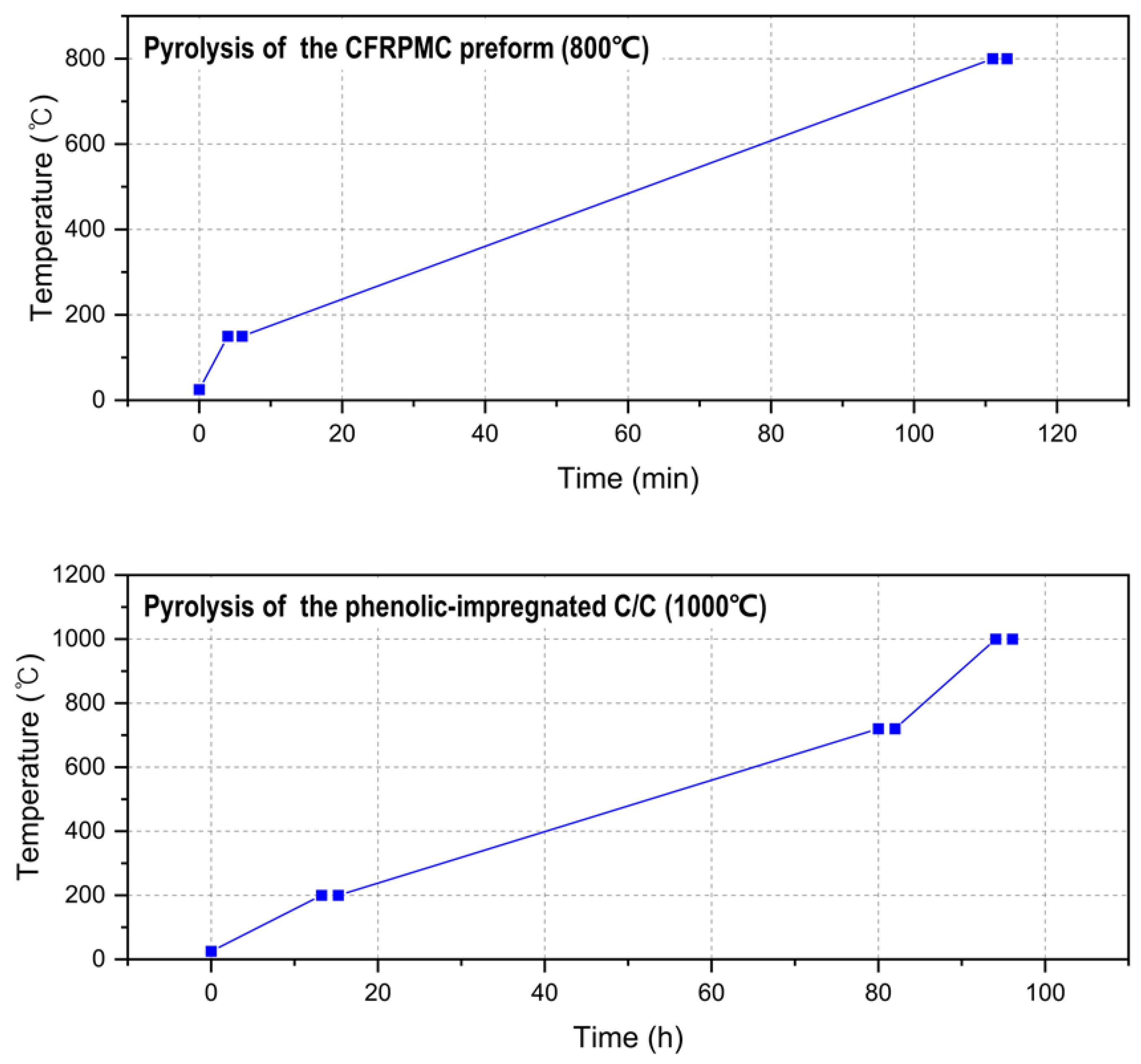
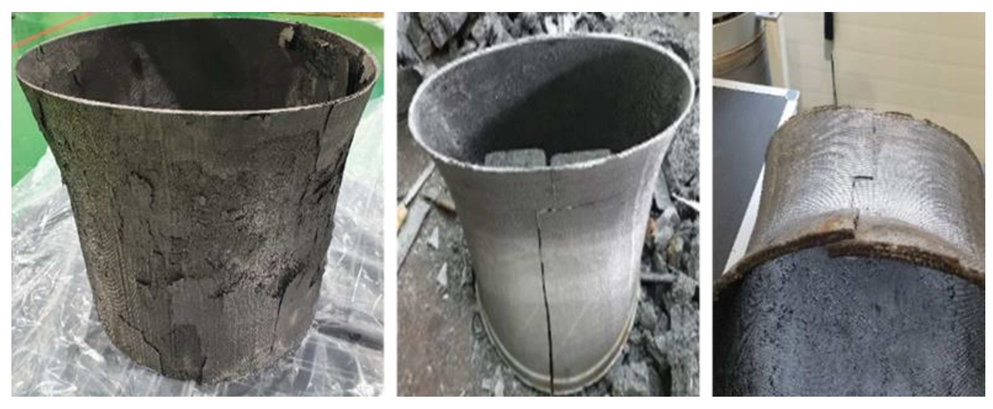
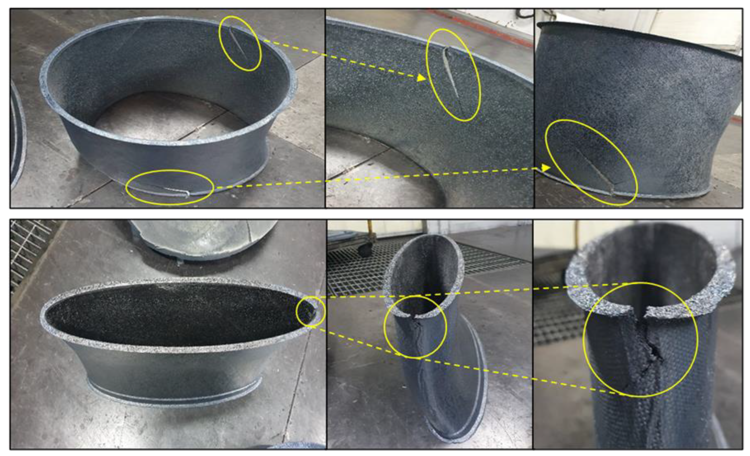
2.2.1. Pyrolysis of the CFRPMC Preform and Densification of the C/C

Although the CFRPMC preform provides useful mechanical strength, it must first be pyrolyzed to convert it into a porous C/C structure suitable for subsequent C/SiC production with enhanced thermal and oxidation resistance. Without pyrolysis, the preform lacks sufficient porosity for molten silicon to infiltrate during LSI. Additionally, residual carbon generated during pyrolysis protects the carbon fibers and serves as a reactant for the in situ formation of the SiC matrix [27]. However, pyrolysis also induces significant shrinkage and density reduction, necessitating a densification process involving multiple cycles of resin impregnation and re-pyrolysis to increase the carbon content.
In this study, to constrain the preform (initial density: 1.49–1.57 g/cm3) against distortion during high-temperature exposure, the CFRPMC lay-up was wrapped with carbon-fiber tows and then pyrolyzed in a nitrogen atmosphere at 800 °C. This pyrolysis decomposed the phenolic matrix, yielding a porous C/C structure with a reduced density of 1.29–1.42 g/cm3. The preform remained in its plaster mold during pyrolysis to prevent deformation; the mold itself disintegrated under high-temperature conditions.
Although the porous C/C could proceed directly to LSI, its low carbon content risks incomplete SiC conversion and excessive residual silicon, which degrade both oxidation resistance and high-temperature mechanical performance. To address this, a single densification cycle was employed: the C/C preform was vacuum-impregnated with phenolic resin and then subjected to a second pyrolysis. In contrast to conventional C/C processes that may require multiple cycles, a single impregnation–pyrolysis cycle here preserved sufficient porosity for effective silicon infiltration.
To minimize distortion during the second, higher-temperature pyrolysis, graphite fixtures were installed on the top and bottom surfaces of the low-density C/C preform. A central graphite column held these fixtures in place, and six peripheral vent holes accommodated carbon fiber tow passages and facilitated gas escape. The fixtures were machined to the final part dimensions, accounting for 2–5% of the design margins. Four slits at the outer fixture edges provided mechanical compliance, absorbing residual stresses and preventing preform damage.
The graphite-fixtured C/C preform was placed in an impregnation chamber and vacuum-infused with phenolic resin for 2 h. After impregnation, the preform was cured at 120 °C for 10 h. It then underwent a second pyrolysis at 1000 °C, completing the densification and raising the C/C density to approximately 1.45–1.46 g/cm3. The overall densification workflow and the temperature–time profiles for both pyrolysis steps are shown in Figure 10 and Figure 11, respectively.
As shown in Figure 11, the dwell time at 1000 °C is substantially longer than that at 800 °C. While thermal expansion and shrinkage during the first pyrolysis are manageable, the increased carbon content after densification makes the preform more susceptible to thermal stresses, risking interlaminar delamination or cracking under rapid heating. Initially, temperatures were increased by 100 °C every 5 h; however, this led to defects (Figure 12). To prevent damage, the heating rate was slowed, and extended isothermal holds were introduced at each ramp change, allowing the structure to stabilize. Specifically, 2 min holds used at 800 °C were replaced by 2 h dwells at each interval during the 1000 °C pyrolysis. Because delamination was most pronounced near 600 °C, the process employed an especially slow ramp between 200 °C and 720 °C to mitigate the thermal gradients. After reaching 1000 °C, natural cooling was achieved by turning off the furnace power.

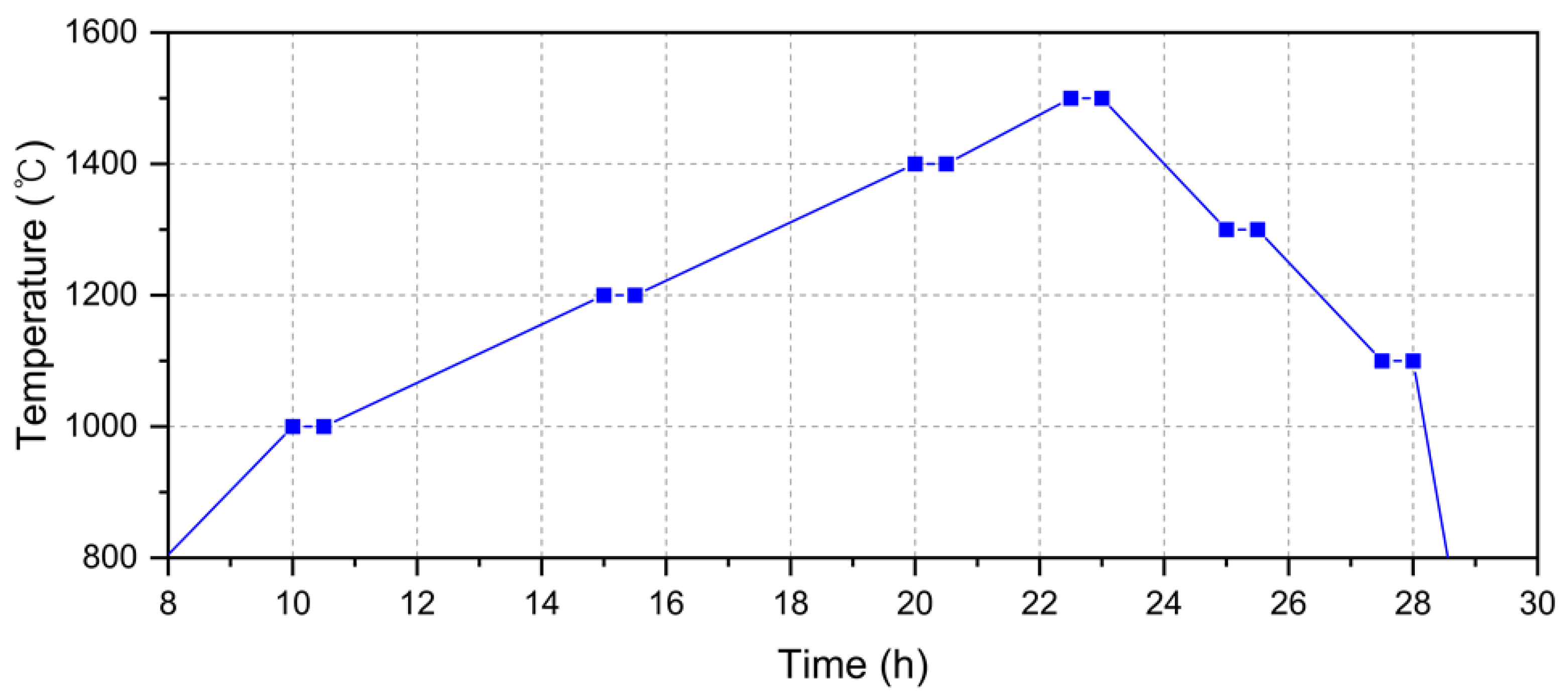
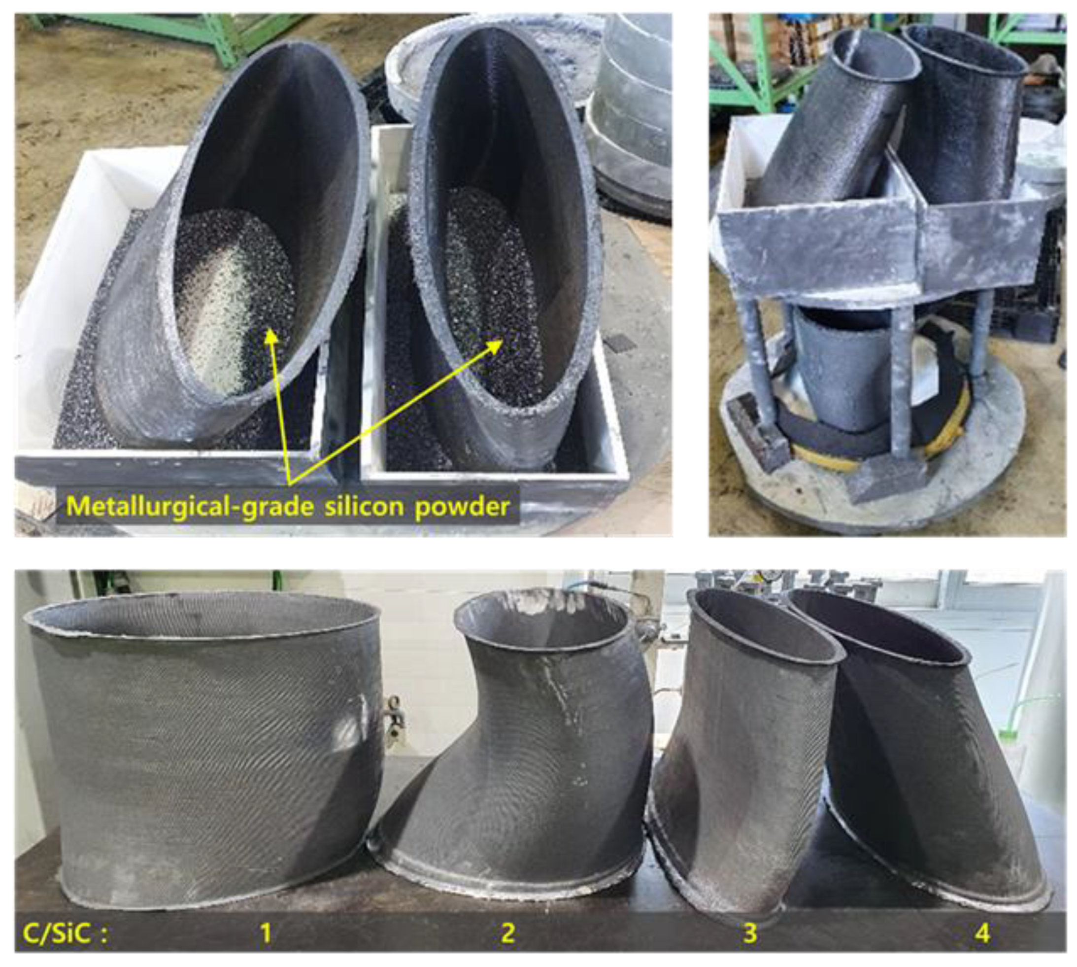
2.2.2. Heat Treatment of the Densified C/C Preform and the LSI Process

Because the LSI process operates at a temperature more than 500 °C higher than the preceding densification step, post-heat treatment of the densified C/C preform is essential to prevent thermal deformation and cracking during silicon infiltration. To enhance thermal stability and relieve residual stress, the preform was heat-treated at 1500 °C, close to the LSI temperature. The heating profile included 30 min isothermal holds at every 200 °C increment from 1000 °C to 1500 °C [30,31], resulting in a total heating duration of approximately 12.5 h.
During the 1500 °C treatment, cracks frequently appeared at the inlet and outlet sections, where the preform was tightly constrained by graphite fixtures. Shrinkage during cooling induced excessive stress at the contact interfaces (Figure 13). Omitting fixtures entirely led to unacceptable thermal deformation. Therefore, fixtures remained necessary, and shrinkage-induced failures were mitigated by preemptively oversizing the inlet and outlet inner diameters by 2–5% (as described in Section 2.2.1) and by implementing controlled cooling: the temperature was first reduced in stages down to 1000 °C, then cooled under a nitrogen atmosphere below 1000 °C.
To further enhance structural stability during thermal cycling, carbon fiber tows were wound around the outer surface of the preform. Vertical reinforcement was provided by threading fiber tows through pre-drilled holes in the top and bottom graphite fixtures, allowing the tows to span the full preform height and constrain vertical deformation. After heat treatment, the preform’s density remained essentially unchanged. The detailed temperature–time profile for the 1500 °C post-heat treatment is shown in Figure 14, and comparison photographs before and after the 1500 °C treatment are shown in Figure 15.
After heat treatment, all carbon fiber tows and graphite fixtures were removed to prevent unintended bonding during LSI. The preform was then placed in a crucible lined with metallic silicon powder and loaded into the LSI furnace. The temperature was raised to 1550 °C and held for 1 h to melt the silicon, which infiltrated the porous C/C via capillary action and reacted in situ to form an SiC matrix. Cooling was again staged—first to 900 °C and then under nitrogen—to avoid shrinkage-induced damage. The resulting C/SiC exhibited an average density of 1.72 g/cm3. The LSI temperature–time profile and segmented-nozzle photographs before and after infiltration are presented in Figure 16 and Figure 17, respectively.
Implementing the patch-type lay-up combined with optimized thermal and cooling history control significantly reduced the defect rate during pyrolysis and silicon infiltration from over 50% in continuous wound configurations to approximately 5% with patch-type lay-ups. This improvement can be attributed to the reduced residual stress concentrations and improved thermal strain distribution achieved by avoiding continuous hoop tension, excessive internal stresses, and circumferential compression in complex curved geometries during pyrolysis and LSI. The segmental lay-up inherently provides localized strain relief during heating and cooling, suppressing radial cracking. Furthermore, the proposed heating and cooling strategy, including controlled heating rate, soaking stages, and gradual cooling, minimized internal stresses and prevented delamination and cracking. These combined effects highlight the importance of both geometry-adaptive lay-up design and thermal management in ensuring the structural integrity of large-scale ceramic matrix composites.

2.3. Multilayer Exhaust Nozzle Fabrication

The C/SiC nozzle was finalized by machining and assembling the segmented C/SiC parts, followed by sequential lamination of a thermal-insulation layer and an outer reinforcement layer to complete the prototype. The fabrication procedure comprised precision machining, bonding and assembly of the segmented parts, application of thermal insulation, and outer CFRPMC reinforcement. The final nozzle structure is a three-layer laminate, including (1) an innermost C/SiC layer to withstand high-temperature, high-velocity exhaust gases and oxidation, (2) a middle silica fiber-reinforced phenolic composite layer serving as thermal insulation to suppress heat transfer to the outer surface, and (3) an outer phenolic-based CFRPMC layer providing structural reinforcement and surface protection.

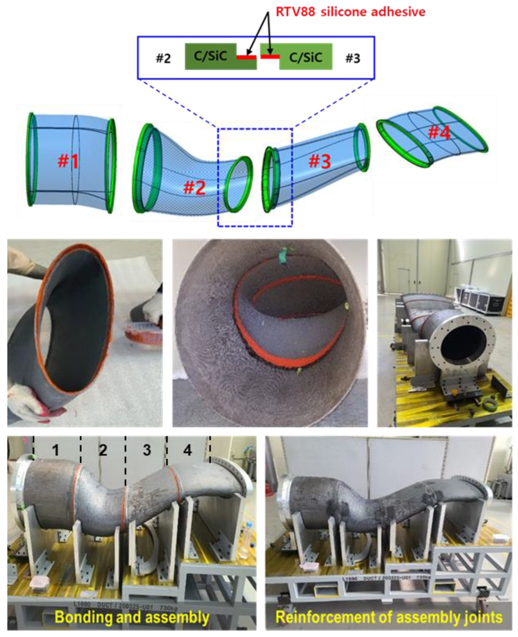
2.3.1. Assembly and Bonding of Segmented C/SiC Nozzle Parts

The completed exhaust nozzle measures 1.6 m in length and consists of four segmented C/SiC parts. To ensure accurate alignment, a dedicated assembly fixture was manufactured to tight dimensional tolerances; this fixture also permitted final dimensional inspection (Figure 18).
Despite thermal control measures to minimize deformation and cracking, repeated high-temperature processing introduced minor dimensional deviations within the allowable range. To ensure precise alignment of parts #1–#4, each C/SiC segment underwent precision machining. A trial assembly in the jig then identified and resolved any fit-up issues prior to the final bonding. The bonding, assembly, and multilayer lay-up process is shown in Figure 19.
Segment interfaces were machined with complementary male–female geometries to simplify assembly. The joints were bonded using a high-temperature silicone adhesive (RTV88, Momentive Performance Materials Inc., New York, NY, USA). To prevent misalignment or distortion during adhesive curing, carbon fiber/phenolic prepregs were wrapped locally around each joint. Both the adhesive and the prepregs were cured at room temperature for 24 h.

2.3.2. Thermal Insulation and Outer Reinforcement Layer Forming

To suppress radiant heat and protect the outer reinforcement layer from high temperatures, a silica fiber-reinforced phenolic insulation layer was applied. Prepregs, 0.7 mm thick, were laminated onto the assembled C/SiC nozzle until a total insulation thickness of 5 mm was achieved. The entire assembly was vacuum-bagged and cured at 150 °C for 2.5 h.
For mechanical reinforcement and outer-surface protection, phenolic-based CFRPMC prepregs (0.2 mm thick) were laminated atop the cured insulation layer to a total thickness of 5 mm. This outer layer was vacuum-bagged and cured at room temperature for 24 h.
To interface with the engine, rear aft-deck, and IR-signature evaluation fixtures, flanges were required at both ends and at the nozzle’s center. These flanges were fabricated from CFRPMCs using metal molds (as high-temperature molding was unnecessary). The prepregs were laminated in the mold and autoclave-cured at 150 °C under 276 kPa for 2 h. The flanges were bonded to the nozzle ends with an RTV88 adhesive and cured at room temperature for 24 h. Additional joint reinforcement was provided by wrapping carbon fiber/phenolic prepregs around the bonding regions and curing them again at room temperature for 24 h.
Because conventional molding could not accommodate the center-section geometry, the mid-nozzle flange was formed in situ by folding the prepreg layers into an inverted “T” (lip) shape and symmetrically laminating them on both sides of the joint. This assembly was also cured at room temperature for 24 h. Finally, bolt holes were machined into all flanges to allow mechanical fastening to the engine, aft-deck, and test fixtures. With these steps completed, a multilayer composite exhaust nozzle for a low-observable UAV was fully fabricated. The processes for insulation lamination, outer reinforcement lay-up, and flange bonding are shown in Figure 20 and Figure 21.

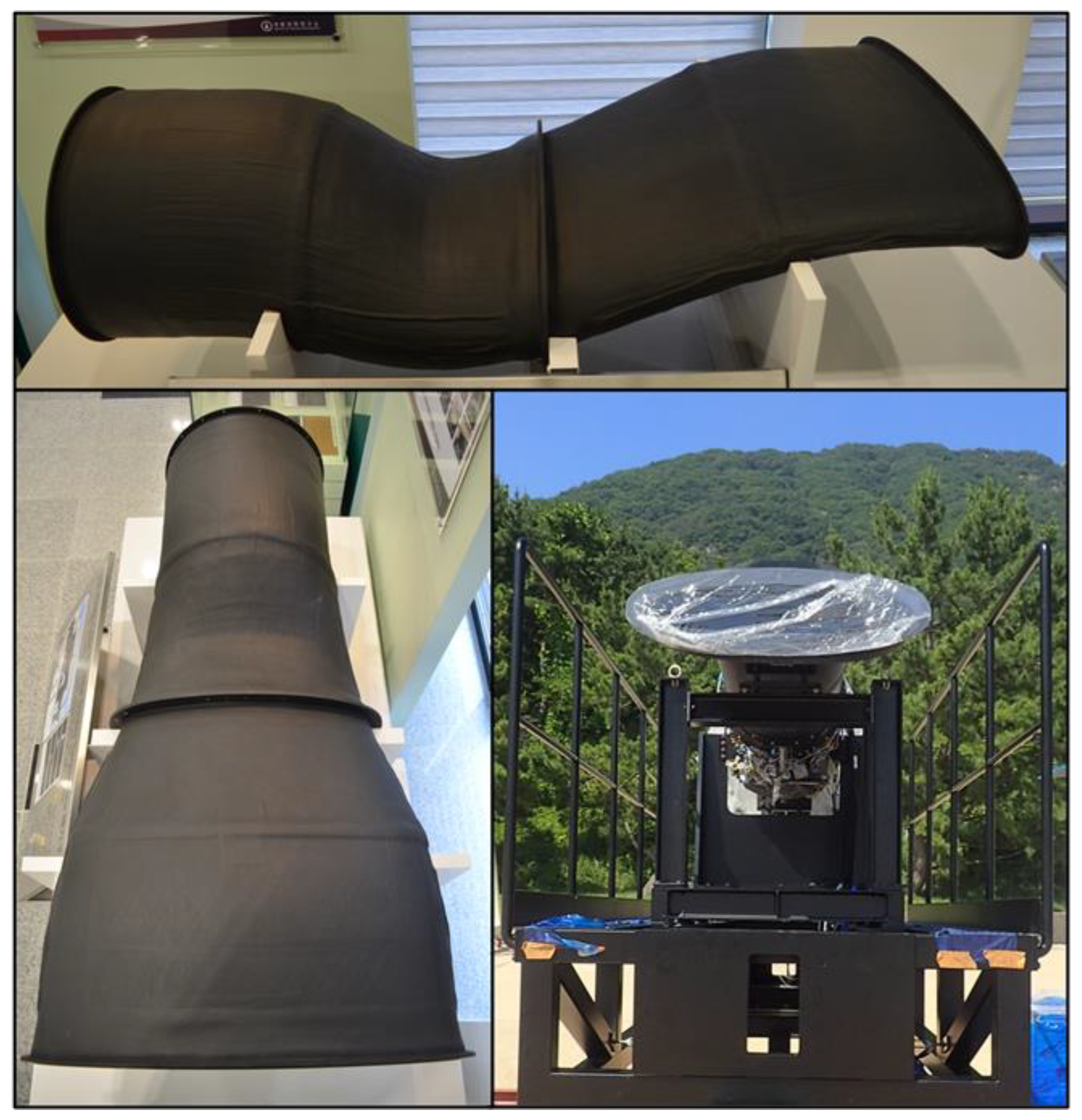
2.3.3. Integration with the UAV Turbofan Engine

Figure 22 shows photographs of the completed composite exhaust nozzle mounted on a turbofan engine (thrust: 6672 N, ~1500 lbf class) for IR-signature suppression evaluation. The assembled nozzle measures 1.64 m in overall length, with an aft-end width of 0.76 m. At under 55 kg, it achieves over a 40% weight reduction compared with conventional metallic nozzles. In addition to aerodynamic and geometric advantages, the DS composite design exhibits substantially lower surface thermal conductivity than metallic materials, enhancing IR-signature reduction and improving UAV mission survivability. Furthermore, the reduced mass is expected to significantly extend the platform’s operational range.

3. Test Results and Discussion

3.1. Physical and Mechanical Properties of C/SiCs

To evaluate the material properties of the C/SiCs, we measured the density, thermal conductivity, and the coefficient of thermal expansion (CTE) and conducted tensile and compressive tests. The density was determined using the apparent-density method, which accounts for the total volume, including internal porosity introduced during processing. Thermal conductivity and CTE measurements, as well as tensile and compressive tests, were conducted following Korean Industrial Standards (KS) L 1604 (Fine ceramics—Determination of thermal diffusivity, specific heat capacity, and thermal conductivity of monolithic ceramics by laser flash method), KS M International Organization for Standardization (ISO) 11359-2 (Thermomechanical analysis method—Part 2: Determination of coefficient of linear thermal expansion and glass transition temperature), the American Society for Testing and Materials (ASTM) D638, and ASTM D695, respectively. The tensile and compressive properties were measured using a universal testing machine (5882, Instron, Norwood, MA, USA). The crosshead speed was set to 1 mm/min for the tensile test and 1.27 mm/min for the compressive test. Prior to testing, the width and thickness of each specimen were measured using a Vernier caliper and input into the test software. Strain gauges were affixed to the specimens, which were then mounted in the appropriate grips for tensile tests or jigs for compression testing. Five specimens were tested under each condition, and the average strength value was calculated after excluding the maximum and minimum values. All procedures followed the corresponding ASTM standards to ensure repeatability and accuracy. The results are summarized in Table 4.
The simulation results shown in Figure 5 and Figure 6 indicate that the maximum internal pressure within the nozzle reaches approximately 150 kPa. Based on this value, both the measured tensile and compressive strengths of the C/SiC are considered structurally sufficient under the expected hoop and axial stresses. Furthermore, the addition of the CFRPMC outer reinforcement layer is estimated to increase the overall safety margin by three to five times.
The thermal conductivity of the C/SiC is higher than that of conventional CFRPMCs, but lower than that of metallic nozzle materials such as nickel-based superalloys [24]. While higher thermal conductivity aids in preventing localized overheating, it can undesirably transfer heat to the outer CFRPMC layer. This issue was addressed by incorporating an intermediate silica fiber-reinforced phenolic insulation layer. Moreover, the CTE of the C/SiC is more than an order of magnitude lower than that of typical metals, indicating excellent dimensional stability under high-temperature conditions [32]. Consequently, C/SiC is particularly well-suited for high-temperature engine-nozzle applications.
In summary, the C/SiC composite exhibits thermal and dimensional properties that make it a suitable candidate for exhaust-nozzle structures operating at elevated temperatures. Even at service temperatures of around 500 °C, the material maintains structural integrity with minimal thermal deformation. Additionally, owing to the high oxidation resistance of the SiC matrix and the oxygen-deficient nature of high-temperature exhaust gases, the composite is expected to perform reliably during prolonged operations. For further protection, a ceramic plasma-sprayed coating on the internal surface is planned to enhance oxidation and ablation resistance.

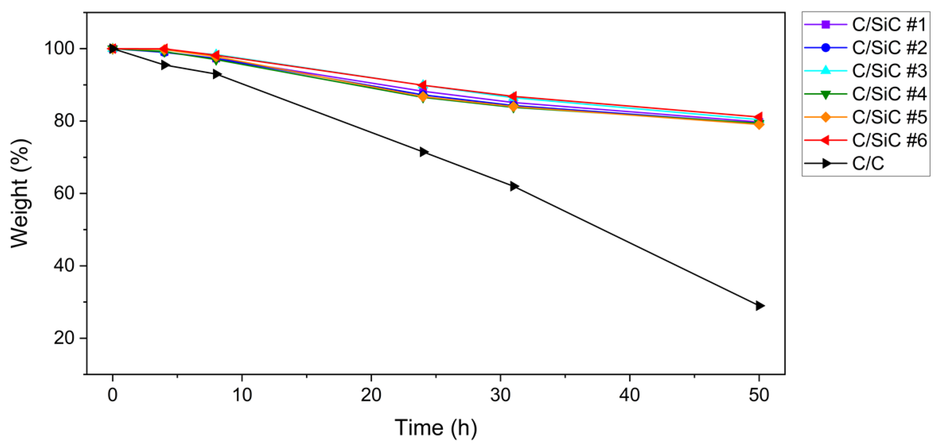
3.2. Oxidation and Ablation Resistance Tests

To assess high-temperature oxidation resistance, isothermal oxidation tests were conducted at 500 °C for 50 h in a high-temperature furnace. Specimens sectioned from defective nozzle parts that had undergone full LSI processing were weighed before and after exposure to determine mass loss. As shown in Figure 23, conventional C/C composites lost approximately 71% of their mass after 50 h under oxidizing conditions. In contrast, the C/SiC composite exhibited only approximately 20% weight loss under the same conditions, confirming the superior oxidation resistance of the SiC matrix compared to the pure carbon matrix.
Ablation resistance was evaluated using a custom-built oxy-kerosene torch system. The specimens were exposed to a flame that maintained their surface temperature at approximately 1000 °C for 20 min. Photographs of the torch test setup and the post-test specimen surface are shown in Figure 24. After testing, total mass loss was under 7%, demonstrating that the material endured the severe thermal load with minimal surface degradation. Although these conditions exceeded the intended service environment, the C/SiC maintained excellent ablation resistance.
Given these results, applying a ceramic coating via vacuum plasma spraying is expected to further enhance the composite’s long-term oxidation and ablation resistance in operational settings [33].

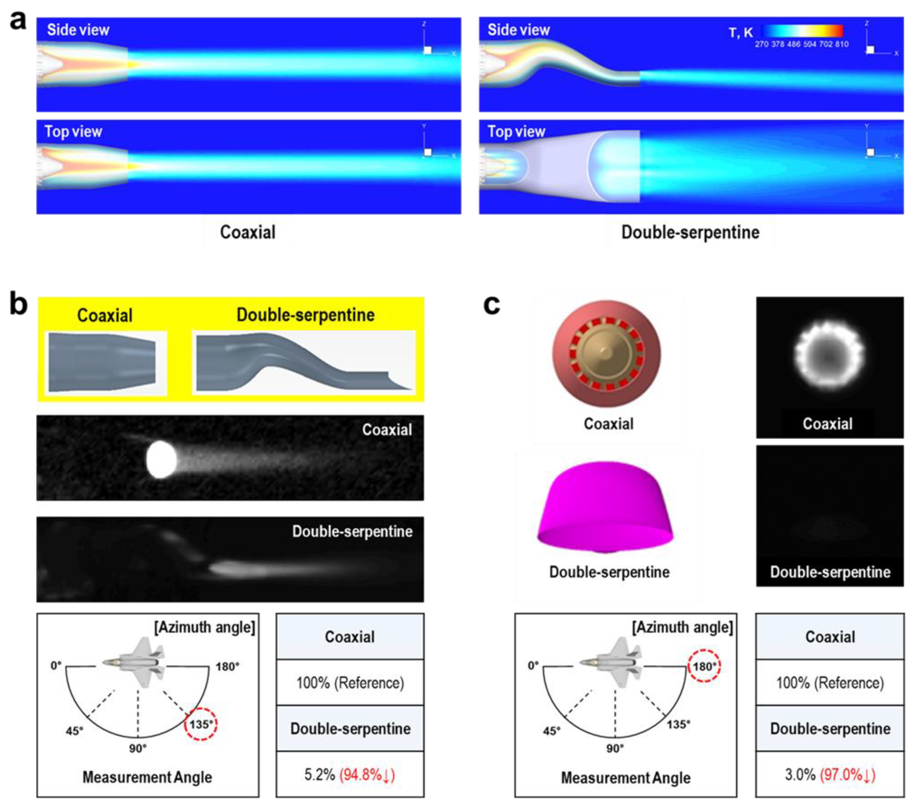
3.3. IR-Signature Measurement Test

To evaluate IR-signature reduction performance, we conducted comparative tests by mounting both the DS-type C/SiC nozzle and a conventional coaxial metallic nozzle, each with an identical metallic aft-deck, on the same turbofan engine. High-resolution IR spectrometers (Hyper-Cam, TELOPS Inc., Quebec, QC, Canada; MR170, ABB Measurement & Analytics, Zurich, Switzerland) and IR imaging cameras (T650SC, FLIR Systems Inc., Wilsonville, OR, USA) were used to quantify and visualize IR suppression. The results are presented in Figure 25.
Figure 25a shows simulated exhaust-plume profiles and temperature distributions from the side and top views, illustrating differences attributable to nozzle geometry. To simulate both internal and external flow fields, the compressible Navier–Stokes equations were solved. Inviscid fluxes were computed using Roe’s flux-difference splitting scheme, and flow variables were reconstructed using the linear least-squares method. Time integration was performed using an implicit scheme under steady-state conditions. The k-ω SST turbulence model was adopted to account for turbulence effects. The accuracy and reliability of the computational approach were validated by comparing the simulation results with experimental data from a baseline coaxial (non-stealth-type) nozzle configuration.
Figure 25b presents actual IR measurements taken at an azimuth of 135°, revealing that the coaxial metallic nozzle exhibited significantly higher IR intensity owing to the direct discharge of hot gases. By contrast, the DS-type C/SiC nozzle, incorporating IR-signature-reduction design features, achieved a 94.8% reduction in IR intensity relative to the metallic variant.
Furthermore, Figure 25c shows IR measurements from a rear view (azimuth 180°, elevation 0°), where the DS-type C/SiC nozzle achieved 97% IR suppression compared with the coaxial nozzle. This improvement arises from both geometric shielding by the DS configuration and the superior high-temperature resistance and insulation properties of the multilayer composite, which effectively block thermal radiation from the hot-section exhaust.

4. Conclusions

This study developed a manufacturing process for a DS-type C/SiC-based exhaust nozzle for UAVs. The objective was to establish a method capable of fabricating large, geometrically complex composite nozzles that withstand high-temperature, high-velocity exhaust flows while providing IR-signature reduction. To meet the mechanical, thermal, and stealth requirements, a three-layer structure was designed comprising an inner C/SiC layer, a middle silica fiber-reinforced phenolic insulation layer, and an outer CFRPMC layer.
The C/SiC preform was produced by stacking carbon fiber/phenolic prepregs on a gypsum mold and by autoclave curing. After pyrolysis and densification, it was converted to a C/C with a density of 1.46 g/cm3. The nozzle was then fabricated using LSI, wherein molten silicon infiltrated the porous C/C, reacting in situ to form an SiC matrix. Four segmented C/SiC components were produced, precisely machined, and bonded with a high-temperature-resistant silicone adhesive. A silica fiber/phenolic prepreg layer was applied for thermal insulation, followed by a carbon fiber/phenolic prepreg lay-up for mechanical reinforcement, completing the multilayer assembly.
Mechanical testing confirmed that the composite met all design targets, and high-temperature oxidation and ablation tests confirmed excellent durability and resistance. IR-signature measurements on a ground-based system showed that the DS-type C/SiC nozzle achieved substantially greater IR suppression than the baseline coaxial metallic nozzle.
In summary, a large, complex-geometry, multilayer composite exhaust nozzle was successfully fabricated using the LSI process. The developed manufacturing approach promises to advance the future production of high-temperature-resistant, large-scale, and geometrically intricate composite structures. Additionally, the IR-signature suppression technology and evaluation methodology established here are expected to support the design of low-observable stealth aerial platforms, enhancing stealth performance and maximizing platform survivability.

Author Contributions

Conceptualization, B.-J.K., M.Y.L. and C.W.B.; methodology, B.-J.K., J.W.K., M.Y.L. and J.K.P.; software, J.W.K. and C.W.B.; validation, B.-J.K. and J.W.K.; formal analysis, B.-J.K., J.W.K. and M.Y.L.; investigation, B.-J.K., J.W.K., M.Y.L. and N.C.C.; resources, M.Y.L. and C.W.B.; data curation, B.-J.K. and J.W.K.; writing—original draft preparation, B.-J.K.; writing—review and editing, B.-J.K.; visualization, B.-J.K., J.W.K. and M.Y.L.; supervision, B.-J.K.; project administration, M.Y.L.; funding acquisition, M.Y.L. All authors have read and agreed to the published version of the manuscript.

Funding

This work was supported by the Agency for Defense Development Grant, funded by the Korean Government (912822501).

Data Availability Statement

Data are unavailable due to military security concerns.

Conflicts of Interest

The authors declare that they have no known competing financial interests or personal relationships that could have appeared to influence the work reported in this paper.

Abbreviations

The following abbreviations are used in this manuscript:
DSDouble-serpentine
UAVUnmanned aerial vehicle
C/SiCCarbon fiber-reinforced silicon carbide matrix composite
PMCPolymer matrix composite
CFRPMCCarbon fiber-reinforced polymer matrix composite
C/CCarbon fiber-reinforced carbon matrix composite
SiC/SiCSilicon carbide fiber-reinforced silicon carbide matrix composite
LSILiquid silicon infiltration
PANPolyacrylonitrile
CTECoefficient of thermal expansion

References

  1. Li, M.; Chen, J.; Feng, X.; Qu, F.; Bai, J. An efficient adjoint method for the aero-stealth shape optimization design. Aerosp. Sci. Technol. 2021, 118, 107017. [Google Scholar] [CrossRef]
  2. Bo, L.; Wang, Q.; Hu, H. Multidisciplinary design optimization of axisymmetric exhaust systems: Integrating aerodynamic performance and infrared stealth capabilities. Inter. J. Therm. Sci. 2025, 208, 109462. [Google Scholar] [CrossRef]
  3. Lee, C.; Choi, S.M. Study on the Effects of Aft Deck Geometry on Plume Shield Ratio. Inter. J. Aeronaut. Space Sci. 2025, 26, 1–12. [Google Scholar] [CrossRef]
  4. Shi, J.; Zhou, L.; Xu, J.; Shi, J.; Wang, Z. Experimental Study on Infrared Radiation Characteristics and Matching Performance of Low-Observable Nozzles. J. Propuls. Power 2024, 40, 354–367. [Google Scholar] [CrossRef]
  5. Kim, S.J.; Kim, Y.R.; Kim, Y.; Kim, M.H.; Lee, M. 2D exhaust nozzle with multiple composite layers for IR signature suppression. Results Phys. 2020, 19, 103395. [Google Scholar] [CrossRef]
  6. Guo, B.-F.; Wang, Y.-J.; Cao, C.-F.; Qu, Z.-H.; Song, J.; Li, S.-N.; Gao, J.-F.; Song, P.; Zhang, G.-D.; Shi, Y.-Q.; et al. Large-Scale, Mechanically Robust, Solvent-Resistant, and Antioxidant MXene-Based Composites for Reliable Long-Term Infrared Stealth. Adv. Sci. 2024, 11, 2309392. [Google Scholar] [CrossRef]
  7. Zhao, J.; Yang, J.; Wang, Z.; Wang, Y.; Jin, X.; Li, P.; Liu, P.; Chen, K.; Yang, L.; Fan, X. Thermal shock resistance and failure mechanisms of high temperature resistant radar and infrared compatible stealth coatings. Surf. Coat. Technol. 2023, 465, 129613. [Google Scholar] [CrossRef]
  8. Wang, X.; Gao, X.; Zhang, Z.; Cheng, L.; Ma, H.; Yang, W. Advances in modifications and high-temperature applications of silicon carbide ceramic matrix composites in aerospace: A focused review. J. Eur. Ceram. Soc. 2021, 41, 4671–4688. [Google Scholar] [CrossRef]
  9. Sengupta, P.; Manna, I. Advanced High-Temperature Structural Materials for Aerospace and Power Sectors: A Critical Review. Trans. Indian Inst. Met. 2019, 72, 2043–2059. [Google Scholar] [CrossRef]
  10. Bencivengo, R.; Stoica, A.I.; Leonov, S.B.; Gulotty, R. Experimental Characterization of C–C Composite Destruction Under Impact of High Thermal Flux in Atmosphere and Hypersonic Airflow. Aerospace 2025, 12, 43. [Google Scholar] [CrossRef]
  11. Han, M.; Zhou, C.; Silberschmidt, V.V.; Bi, Q. Oxidation behaviour and residual mechanical properties of carbon/carbon composites. Carbon Lett. 2023, 33, 1241–1252. [Google Scholar] [CrossRef]
  12. Fu, Z.; Pang, A.; Luo, H.; Zhou, K.; Yang, H. Research progress of ceramic matrix composites for high temperature stealth technology based on multi-scale collaborative design. J. Mater. Res. Technol. 2022, 18, 2770–2783. [Google Scholar] [CrossRef]
  13. Guo, G.; Ye, F.; Cheng, L.; Li, Z.; Zhang, L. A novel porous carbon synthesized to serve in the preparation of highly dense and high-strength SiC/SiC by reactive melt infiltration. Compos. Part A Appl. Sci. Manuf. 2024, 176, 107839. [Google Scholar] [CrossRef]
  14. Yilmaz, S.; Theodore, M.; Ozcan, S. Silicon carbide fiber manufacturing: Cost and technology. Compos. Part B Eng. 2024, 269, 111101. [Google Scholar] [CrossRef]
  15. Zhang, Q.; Chen, T.; Kang, W.; Xing, X.; Wu, S.; Gou, Y. Synthesis of Polytitanocarbosilane and Preparation of Si–C–Ti–B Fibers. Processes 2023, 11, 1189. [Google Scholar] [CrossRef]
  16. Wang, J.; Lin, M.; Xu, Z.; Zhang, Y.; Shi, Z.; Qian, J.; Qiao, G.; Jin, Z. Microstructure and mechanical properties of C/C–SiC composites fabricated by a rapid processing method. J. Eur. Ceram. Soc. 2009, 29, 3091–3097. [Google Scholar] [CrossRef]
  17. Yao, X.Y.; Li, W.; Feng, G.H. Effect of C/C preform density on oxidation properties of C/C-SiC composites. IOP Conf. Ser. Mater. Sci. Eng. 2020, 733, 012012. [Google Scholar] [CrossRef]
  18. Liu, Z.; Wang, Y.; Xiong, X.; Ye, Z.; Long, Q.; Wang, J.; Li, T.; Liu, C. Microstructure and Ablation Behavior of C/C-SiC-(ZrxHf1−x)C Composites Prepared by Reactive Melt Infiltration Method. Materials 2023, 16, 2120. [Google Scholar] [CrossRef]
  19. Xu, C.; Yi, F.; Meng, S.; Huo, Y.; Han, X.; Yang, Q. Compressive experimental method and properties of C/C composites under ultra-high temperature environment. J. Eur. Ceram. Soc. 2022, 42, 4702–4711. [Google Scholar] [CrossRef]
  20. Gauthier, M.M. Carbon-Carbon Composites. Eng. Mater. Handb. Desk Ed. 1995, 48, 1094–1111. [Google Scholar] [CrossRef]
  21. Xiao, J.; Zhang, H.-Y.; Gong, S.-K.; Xu, H.-B.; Guo, H.-B. High-temperature oxidation resistance of Si-coated C/SiC composites. Rare Met. 2024, 43, 4566–4572. [Google Scholar] [CrossRef]
  22. DiCarlo, J.A.; Yun, H.M.; Morscher, G.N.; Bhatt, R.T. SiC/SiC Composites for 1200 °C and Above. In Handbook of Ceramic Composites; Bansal, N.P., Ed.; Springer: Boston, MA, USA, 2005; pp. 77–98. [Google Scholar]
  23. Liu, X.; Li, L. Design, Fabrication and Testing of Aeroengine Ceramic-Matrix Composite Components, 1st ed.; Springer: Singapore, 2024. [Google Scholar]
  24. Patel, M.; Saurabh, K.; Prasad, V.V.B.; Subrahmanyam, J. High temperature C/C–SiC composite by liquid silicon infiltration: A literature review. Bull. Mater. Sci. 2012, 35, 63–73. [Google Scholar] [CrossRef]
  25. Cheng, L.; Xu, Y.; Zhang, L.; Yin, X. Oxidation behavior of three dimensional C/SiC composites in air and combustion gas environments. Carbon 2000, 38, 2103–2108. [Google Scholar] [CrossRef]
  26. Cramer, C.L.; Yoon, B.; Lance, M.J.; Cakmak, E.; Campbell, Q.A.; Mitchell, D.J. Additive Manufacturing of C/C-SiC Ceramic Matrix Composites by Automated Fiber Placement of Continuous Fiber Tow in Polymer with Pyrolysis and Reactive Silicon Melt Infiltration. J. Compos. Sci. 2022, 6, 359. [Google Scholar] [CrossRef]
  27. Gallegos, I.; Varshney, V.; Kemppainen, J.; Odegard, G.M. Revealing nanoscale mechanisms of pyrolysis at phenolic resin/carbon fiber interface. J. Mater. Sci. 2025, 60, 5106–5124. [Google Scholar] [CrossRef]
  28. Souza, W.; Garcia, K.; Dollinger, C.; Pardini, L. Electrical Behavior of Carbon Fiber/Phenolic Composite during Pyrolysis. Mater. Res. 2015, 18, 1209–1216. [Google Scholar] [CrossRef]
  29. Seers, B.; Tomlinson, R.; Fairclough, P. Residual stress in fiber reinforced thermosetting composites: A review of measurement techniques. Polym. Compos. 2021, 42, 1631–1647. [Google Scholar] [CrossRef]
  30. Chen, X.; Cheng, G.; Zhang, J.; Guo, F.; Zhou, H.; Liao, C.; Wang, H.; Zhang, X.; Dong, S. Residual stress variation in SiCf/SiC composite during heat treatment and its effects on mechanical behavior. J. Adv. Ceram. 2020, 9, 567–575. [Google Scholar] [CrossRef]
  31. Knauf, M.W.; Przybyla, C.P.; Shade, P.A.; Park, J.-S.; Ritchey, A.J.; Trice, R.W.; Pipes, R.B. In situ characterization of residual stress evolution during heat treatment of SiC/SiC ceramic matrix composites using high-energy X-ray diffraction. J. Am. Ceram. Soc. 2021, 104, 1424–1435. [Google Scholar] [CrossRef]
  32. Kong, C.; Sun, Z.; Niu, X.; Song, Y. Analytical model of elastic modulus and coefficient of thermal expansion for 2.5D C/SiC composite. J. Wuhan Univ. Technol. Mater. Sci. Ed. 2013, 28, 494–499. [Google Scholar] [CrossRef]
  33. Ge, H.; Zhang, L.; Zhang, H.; Wang, F.; Gao, X.; Song, Y. Cyclic Ablation Properties of C/SiC-ZrC Composites. Aerospace 2024, 11, 432. [Google Scholar] [CrossRef]
Figure 1. Estimated service lifetimes of high-temperature composite materials as a function of temperature, comparing the operational stability of C/Cs, C/SiCs, and SiC/SiCs [19,20,21,22,23,24].
Aerospace 12 00600 g001
Figure 2. Conceptual schematic of the engine exhaust nozzle for a low-observable UAV.
Aerospace 12 00600 g002
Figure 3. Schematic of the DS exhaust nozzle geometry.
Aerospace 12 00600 g003
Figure 4. Schematic of the DS exhaust nozzle for UAVs, showing the overall geometry and key dimensional specifications.
Aerospace 12 00600 g004
Figure 5. Simulated distributions of temperature (top), pressure (middle), and flow velocity (bottom) inside the nozzle.
Aerospace 12 00600 g005
Figure 6. Mach number (top), temperature (middle), and pressure (bottom) profiles across the nozzle cross-section.
Aerospace 12 00600 g006
Figure 7. Segmentation scheme of the exhaust nozzle: parts #1–#4 in the flow direction.
Aerospace 12 00600 g007
Figure 8. Wooden master pattern used for plaster mold fabrication.
Aerospace 12 00600 g008
Figure 9. CFRPMC preform fabrication process using vacuum bagging and autoclave molding.
Aerospace 12 00600 g009
Figure 10. Pyrolysis and densification process for the CFRPMC preform and subsequent C/C.
Aerospace 12 00600 g010
Figure 11. Temperature–time profiles for (Top) the initial 800 °C pyrolysis of the CFRPMC preform and (Bottom) the 1000 °C densification pyrolysis of the phenolic-impregnated C/C.
Aerospace 12 00600 g011
Figure 12. Defects observed during 1000 °C pyrolysis: interlaminar delamination (left) and cracking ((center) and (right)).
Aerospace 12 00600 g012
Figure 13. Fractures observed at fixture contact regions during the 1500 °C post-heat treatment.
Aerospace 12 00600 g013
Figure 14. Temperature–time profile for the 1500 °C post-heat treatment of the densified C/C preform.
Aerospace 12 00600 g014
Figure 15. Photographs of the densified C/C preform before (left) and after (right) 1500 °C post-heat treatment.
Aerospace 12 00600 g015
Figure 16. Temperature–time profile of the LSI process at 1550 °C.
Aerospace 12 00600 g016
Figure 17. Photographs of the segmented exhaust nozzle before and after the LSI process.
Aerospace 12 00600 g017
Figure 18. Schematic of the dedicated assembly jig for the segmented exhaust nozzle.
Aerospace 12 00600 g018
Figure 19. Bonding, assembly, and joint reinforcement of the segmented C/SiC exhaust nozzle components.
Aerospace 12 00600 g019
Figure 20. Lamination of the silica fiber-reinforced phenolic insulation layer onto the C/SiC exhaust nozzle.
Aerospace 12 00600 g020
Figure 21. Bonding and reinforcement of front, rear, and center flanges using CFRPMCs.
Aerospace 12 00600 g021
Figure 22. Completed composite exhaust nozzle mounted on a turbofan engine for IR-signature suppression evaluation.
Aerospace 12 00600 g022
Figure 23. Comparison of oxidation resistance between C/C and C/SiC: weight loss after 50 h at 500 °C in an oxidizing atmosphere.
Aerospace 12 00600 g023
Figure 24. Oxy-kerosene torch test setup and surface condition of the C/SiC specimen after ablation testing.
Aerospace 12 00600 g024
Figure 25. IR-signature comparison between coaxial metallic and DS-type C/SiC nozzles: (a) simulated plume shape and temperature distribution; (b) IR measurement at azimuth 135°, showing a 94.8% reduction with the DS nozzle; (c) rear view (azimuth 180°, elevation 0°), showing 97% IR suppression.
Aerospace 12 00600 g025
Table 1. Properties of the selected carbon fiber.
Tensile Strength
(GPa)
Tensile Modulus
(GPa)
Elongation
(%)
Density
(g/cm3)
Filament Diameter
(μm)
5.52502.21.87.0
Table 2. Prepreg (plain weave carbon fiber fabric/phenolic resin) test report.
Areal Density
(g/m2)
Prepreg Thickness
(mm)
Prepreg Width
(mm)
Resin Content
(%)
Resin Solids Content
(%)
209 ± 130.23 ± 0.21020 ± 1535 ± 560 ± 3
Table 3. Autoclave processing parameters.
Curing Temperature (°C)Cooling Temperature
(°C)
Pressure
(kPa)
Heating Rate
(°C/min)
Curing Time
(h)
150 ± 565276 ± 351.52
Table 4. Physical and mechanical properties of C/SiCs.
Tensile
Strength
(MPa)
Compressive Strength
(MPa)
Thermal Conductivity
(W/(m·K))
Density
(g/cm3)
Coefficient of
Thermal Expansion
(K−1)
25 °C300 °C
108.67 ± 4.04242.33 ± 24.687.067.981.721.088 × 10−6
Disclaimer/Publisher’s Note: The statements, opinions and data contained in all publications are solely those of the individual author(s) and contributor(s) and not of MDPI and/or the editor(s). MDPI and/or the editor(s) disclaim responsibility for any injury to people or property resulting from any ideas, methods, instructions or products referred to in the content.

