Article

Analytical Shaping of a Rocket Nose as a Stage of Preliminary Aerodynamic Modification

by
Adrian Szklarski
1,* and
Robert Głębocki
2
1
Division of Automation and Aeronautical Systems, Faculty of Power and Aeronautical Engineering, Warsaw University of Technology, 00-665 Warsaw, Poland
2
Division of Mechanics, Faculty of Power and Aeronautical Engineering, Warsaw University of Technology, 00-665 Warsaw, Poland
*
Author to whom correspondence should be addressed.
Aerospace 2025, 12(7), 594; https://doi.org/10.3390/aerospace12070594
Submission received: 15 May 2025 / Revised: 19 June 2025 / Accepted: 26 June 2025 / Published: 30 June 2025
(This article belongs to the Section Aeronautics)

Abstract

The article discusses the problem of a preliminary analytical method for modifying the shape of a rocket’s nose. The purpose of this method is to determine the shape that minimizes aerodynamic drag, in the context of modifying a ballistic missile to incorporate guidance systems. The traditional design process relies on numerical methods such as CFD (Computational Fluid Dynamics) or machine learning techniques; however, the method presented here can serve as a first iteration to support the design. Advanced simulation tools are often expensive and difficult to access for smaller companies, while open-source software can sometimes be unreliable, difficult to use, and incompatible with professional solutions. This can pose a challenge for businesses planning to collaborate in the future with large corporations that rely on advanced engineering tools. The proposed solution, as previously mentioned, provides a starting point for the entire design process. The approach has been shown to be sufficient from the design work. The entire process was validated during test range trials, during which rockets were launched, and the flight measurement results accurately reflected the aerodynamic properties of the missiles. In the next stages of the project, numerical methods including CFD simulations are planned to verify the analytical results and enable further aerodynamic modification of the design.

1. Introduction

On today’s battlefields, unguided rockets are still the most common type of missile munitions, due to their low production and operating costs compared to the value of the targets they are intended to destroy. Although they provide a wide area of fire, their disadvantage is a significant discrepancy in the point of impact, which can lead not only to failure to reach the target, but also to accidental damage to civilian objects. As a result, the military is placing increasingly high demands on weapons technology, especially in the context of guided missile development. These criteria include not only the versatility of the weapon, but also its ability to perform complex tasks, precise targeting, and high hit effectiveness.
An example of the evolving requirements in this field are development plans for precision-guided munitions, which indicate dynamic progress of this technology in the armed forces of leading countries worldwide. The available literature presents various approaches to the problem of missile guidance, including widely used navigation methods described, among others, in works [1,2,3,4]. In Poland, there is also a growing number of research and development projects focused on control systems for axisymmetric flying objects [5,6,7,8]. A rocket, as a functionally complex object, requires consideration of many factors and system principles that together create the mechanism for controlling its motion along the flight trajectory. Confirmation of the intense development in this field can be found in numerous publications [9,10,11,12,13], which present various approaches to control systems and innovative methods for guiding guided missiles. Moreover, current scientific and technological achievements enable the implementation of new solutions, such as impact point prediction and advanced analytical tools, including the Monte Carlo method [14].
Both aerodynamics and flight mechanics play a key role in the design process of guided missiles, starting from the conceptual stage through to numerical simulations. This article presents a methodology for the analytical design of the rocket’s front section, which serves as a test platform for guided missiles. The transformation of a ballistic missile into a guided missile required a modification of its front section, which involved providing additional space inside the rocket for the control system. Therefore, this work focuses on analyzing the shape of the rocket’s nose to minimize aerodynamic drag. Analytical methods were used for the preliminary selection of geometric parameters, which can be understood as a stage of preliminary modification. In the further part of the article, the term “modification” refers specifically to this stage of the preliminary project phase. In subsequent stages, the use of formal numerical methods and modification algorithms is planned to further improve the design.
Modern rocket design often requires the use of advanced engineering software, which can be costly and difficult to access, especially for young companies operating in the rocket technology sector. Under such conditions, it is important to have methods that enable quick and efficient preliminary development of designs without the need to invest in expensive tools. The simplified analytical method presented in this work is based on basic technical parameters, summarized in Table 1, and aerodynamic relationships, allowing reliable results to be obtained early in the design process. This method has been validated through practical test range trials, which confirmed its effectiveness. It provides a solid foundation for further design work and integration with more advanced numerical techniques and simulations planned for subsequent stages of the research.
This article does not include a formal mathematical model, which may raise questions among rocket engineers. Such models are necessary for a comprehensive analysis of flight dynamics; however, this work focuses on practical design aspects and aerodynamic analysis of the rocket’s front section, enabling the identification of key factors affecting its efficiency. The omission of a formal model stems from the focus on practical design solutions. While mathematical equations could allow a more precise analysis of the forces acting on the rocket, including them would require a significant theoretical expansion beyond the scope of this paper. Despite the lack of a formal model, the article presents analytical aerodynamic calculations of the rocket’s nose section, providing valuable information for designers. The authors emphasize the practical relevance of the results and plan to extend their research to include detailed mathematical models in the future.
As mentioned earlier, modifying the aerodynamic shape of the rocket is a key element in improving its performance while meeting tactical specifications [15]. Many authors of various studies consider traditional methods based on manual analysis to be difficult and time-consuming. This is indeed a valid statement; however, this paper presents just such a traditional method. Traditional methods obviously have their limitations in terms of performance, so it is recommended to validate them with other available methods, such as machine learning as presented in [15], genetic models as described in [16], or classical CFD models based on basic aerodynamics as discussed in [17]. It is also important to bear in mind that the analysis of the aerodynamic shape of the nose section of a rocket involves many design and scientific aspects, which must also relate to other technical factors such as aerodynamic performance related to heat transfer [18]. While all these factors are important during the analysis, the focus of this paper is on simplifying the topic as much as possible. The method presented above has, of course, been properly verified at later stages of the project using CFD (Ansys, Canonsburg, PA, USA) and Digital DATCOM software, and the correctness of the analysis has been confirmed by field test results. The paper, therefore, proposes a practical, simplified approach to the aerodynamic design of the rocket’s front end without the use of expensive software. Thus, it provides a starting point for further work on guidance systems and rocket flight modeling.

2. Mathematical Model to Minimize the Drag Coefficient of the Rocket Front and Its Internal Volume

The analysis focused on developing a new shape for the front of the rocket, which is shown in Figure 1. The target design also includes control surfaces, although this part is not the subject of this article. The stabilizer system and the caliber of the rocket remain unchanged and provide a reference point for upgrading the rocket.
The current shape of the rocket provides maximum internal volume while maintaining moments of inertia about the lateral axes. Further changes to the rocket’s geometry are aimed at improving its aerodynamic properties, which are key to increasing flight efficiency and range. It is important to emphasize that proper shaping of the front part of the rocket not only reduces drag, but also affects flight stability and trajectory precision. The optimal shape of the front section allows for better pressure distribution, which in turn improves flight stability and trajectory accuracy.
The missile can be divided into three basic geometric shapes, each of which plays a specific role in ensuring optimal aerodynamic and structural properties of the missile. This division is important for further design work aimed at achieving the best possible balance between internal space, aerodynamic stability, and minimizing drag.
  • Aerodynamic forebody shape—this part has an increasing section y x   for x [ 0 ,   d 2 ] ;
  • The cylindrical part of the rocket with a length of l b o d y ;
  • Although the rear section of rockets is usually shaped as a truncated cone to reduce base drag, this particular missile lacks such a configuration.

2.1. The Minimization of the Aerodynamic Drag of a Missile

The minimization of the drag force on an aerodynamic missile is related to determining the shape that provides the best possible balance between drag resistance and the optimal internal volume for the components the missile will carry. The following mathematical models have been taken from the literature [6].
In this regard, the total drag acting on such a surface can be described by the following mathematical model:
P X = 2 π q 0 l _ n o s e y ( x ) y ˙ 4 1 + y ˙ 2 d x
The above formula describes the relationship between drag resistance and the shape of the missile’s nose, and its minimization helps to find the best possible shape that reduces aerodynamic drag. The key role here is played by the function y ( x ) , which represents the shape of the nose and affects how the air interacts with the missile.
The individual components in the formula are as follows:
  • P X : This is the drag resistance per unit length;
  • q : This is the dynamic air pressure, expressed as q = 1 2 ρ v 2 , where ρ is the air density, and v is the missile’s velocity;
  • y ( x ) : This is a function that describes the shape of the missile’s nose profile as a function of its coordinate x , which is the distance along the missile’s axis;
  • y ˙ : This is the derivative of the function y ( x ) , i.e., the slope of the nose profile at point x ;
  • 0 l _ n o s e d x :   Integration along the length of the missile’s nose (from x = 0   to x = L , where L is the length of the missile’s nose).
As a result, the formula expresses the drag per unit length along the missile, which is a function of the nose shape. It consists of several components— y ( x ) y ˙ 4 1 + y ˙ 2 d x —and this expression refers to a specific nose shape. It can be interpreted as a measure of how the shape changes depending on the slope of the profile y ˙ . The term 1 + y ˙ 2   appears because it accounts for the curvature of the nose and how the drag changes depending on how sharply the nose profile changes. The integral 0 l _ n o s e ( ) d x   means that the total drag is calculated by summing (integrating) the contributing drag elements along the entire length of the missile’s nose.
By changing the function y ( x ) , you can obtain different nose profiles for the missile. The goal is to find a shape y x that minimizes the total drag. Changing the shape will affect the value of the integral, and consequently, the drag force. You can treat this as a problem where the goal is to find the most efficient missile nose shape that reduces drag while maintaining other required properties, such as an appropriate volume for transporting payloads.
Continuing with the acceptance of boundary conditions:
x 0 = 0 ,     y 0 = 0 ,     x 1 = L n ,     y 1 = 0.5 d
and introducing relative coordinates:
α = x L n ,         β = 2 y d
The solution can be obtained in a dimensionless form. In this way, for the front part of the rocket defined in this manner, by appropriately assuming the reference surface, the drag coefficient for the front drag is determined [6].
c X = 8 d 2 0 L n y x y ˙ 4 d x
The aerodynamic drag coefficient c x , serving as the objective function, depends on the geometric parameters of the missile’s nose, including the length L n and the shape-defining exponent. Parameters such as the diameter and flight velocity are treated as constant, while L n   and the shape-defining exponent are selected in such a way as to minimize c x . This study performed minimization through an analytical examination of the drag function behavior, without employing formal numerical modification techniques. This approach made it possible to obtain a satisfactory solution that meets the design requirements.
The issue presented here concerns the flight of missiles traveling at subsonic speeds. A similar analysis is carried out for supersonic and hypersonic speeds. In these cases, it is necessary to assume different pressure coefficients, which, for supersonic velocities, are derived from the linearized theory of supersonic jet cone drag, and for hypersonic velocities from the change in particle reflection current. For linearized theories, the above formulae are as follows:
P X M > 1 = 2 π q M 2 1 0 l _ n o s e y ( x ) y ˙ 2 d x
P X h i p = 4 π q 0 l n o s e y x y ˙ 3 1 + y ˙ 2 d x
Given the above boundary conditions, pressure coefficients can be determined:
c X M > 1 = 16 d 2 M 2 1 0 L n y x y ˙ 2 d x
c X _ H i p = 16 d 2 0 L n y x y ˙ 3 d x
Equation (1) is related to the calculation of drag force along the x-axis based on the profile of the nose of the missile, where y x is a function describing the shape of the nose, y ˙   is its derivative (the slope of the profile), and q is the dynamic pressure. Thus, the expression suggests the effect of the profile geometry on aerodynamic drag, considering the forces as a function of shape.
Equation (4) shows the calculation of the aerodynamic drag coefficient c X depending on the shape of the missile nose profile, taking into account its derivative, but without the element ( 1 + y ˙ 2 ) that appears in the first equation. This is a simplified version considering only the drag force without considering geometry, with a more complex function in the denominator.
The expression (7) is used when the missile velocity exceeds the speed of sound (i.e., M > 1), where changes in aerodynamic flow characteristics associated with exceeding the speed of sound are also taken into account. It is therefore a more advanced version for supersonic conditions.
Thus, Equations (1) and (8) are used to calculate different aspects of aerodynamics depending on the geometry of the nose of the rocket. The first equation takes into account a more complex relationship, while the second does not. This means that the two formulae are mutually compatible, but differ in their approach to modeling aerodynamics, which may be due to different assumptions in the calculations. Equation (7) is the version for supersonic speed, which differs from the previous two formulae in that it takes into account the supersonic phenomenon (there is a factor associated with M, or Mach number). This approach is consistent with calculations for supersonic flow, where aerodynamic forces may differ from those for subsonic flow (where the formulae from the first and second equations are applied). Thus, each equation addresses different aspects of missile aerodynamics calculations. The first and second equations are more appropriate for the subsonic case, where the shape of the nose is crucial, while the third equation applies to the supersonic case, taking into account other physical mechanisms (e.g., pressure changes, temperature, flow structure).
Solving these equations for the given functions leads to curves representing the aerodynamic flow contour of the rocket and the drag coefficients. To correctly determine the drag, aerodynamic friction must also be taken into account. This estimation was carried out using a simplified model that assumes a constant fuselage volume, regardless of changes in the length of the rocket’s nose. The above cases of rocket design for a given flight speed can be determined by one general expression:
F [ y ˙ y x ] = y ˙ N y x
In this context, F[ẏ, y(x)] denotes a functional used in the aerodynamic shape modification process. It maps the shape function y(x) and its derivative ẏ to a scalar value representing aerodynamic drag. The exponent N varies depending on the flight regime (e.g., subsonic, supersonic, or hypersonic), as presented in the literature [6].
The functions, depending on the case in question, vary in exponent, but for the missile in question, which, according to Table 1, travels at supersonic speed, the exponent is N = 2 (Formula (9)). This technique was applied to a representative case corresponding to supersonic flight conditions. The method was used for a single research point, specifically for supersonic speed.
Additionally, it should be noted that Equations (5)–(7) initially describe aerodynamic characteristics based solely on the geometric parameters of the missile’s nose, such as the length L n and the shape exponent n . However, since aerodynamic forces are strongly influenced by the flight regime, it is necessary to consider the role of the Mach number M in these formulations. Therefore, to enhance the predictive capabilities of the model for different velocity regimes, the equations may be extended with Mach-dependent corrections. This inclusion allows evaluation of pressure coefficients and drag forces under both subsonic and supersonic conditions using empirical or analytical relations from compressible flow theory. Such an approach ensures a more complete aerodynamic characterization of the missile across a wide range of operating speeds.
Based on the positive results obtained from the tests, conclusions were drawn, suggesting that the above analysis also provides correct results for other speeds when using appropriate values of n = 3 and n = 4, according to the literature [6].
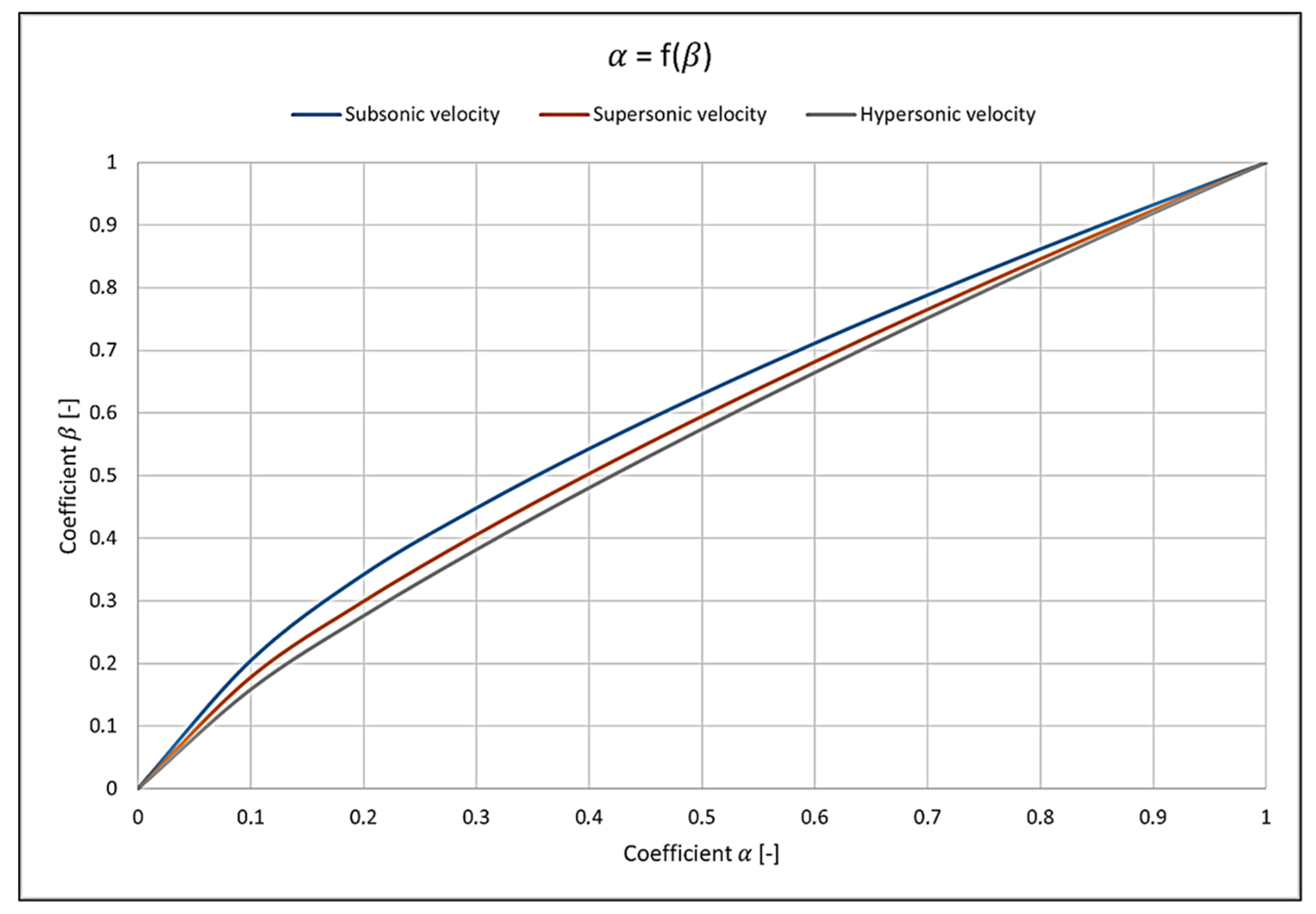
The flight speeds of rocket missiles have a key impact on their aerodynamic design, particularly on the shape of the rocket’s nose, which must be tailored to the conditions encountered during flight. A graphical illustration of these shapes, taking into account different speeds, is shown in Figure 2. Analysis of rockets traveling at supersonic velocity and hypersonic velocity has been carried out, but the results are not discussed in detail in this article. Special attention has been paid to the rocket in question, which moves at supersonic velocity.
Rockets traveling at subsonic speeds usually have a smoother aerodynamic profile, which minimizes drag and ensures stable flight. In contrast, rockets traveling at hypersonic speeds require more advanced shapes that take into account the extreme temperatures and high drag generated by such high speeds. For a rocket traveling at supersonic speeds, the shape of the nose is shown in the “Supersonic Speed” diagram. Supersonic speeds, defined as those exceeding Mach = 1 but falling between Mach = 1 and Mach = 5, require geometries designed to minimize drag while maintaining flight stability.
In order to implement such a shape in a design, it is necessary to determine its mathematical equation from the obtained graph. This equation allows the shape to be accurately reproduced in CAD software [SolidWorks 2018], which is crucial in the structural design process. With the help of CAD tools, the designed profile can be accurately reproduced, taking into account all aerodynamic parameters, allowing further testing and modification of the design. This approach ensures that the final shape of the rocket will be fully adapted to the expected flight speeds and conditions.
In summary, the flight speeds of rocket systems have a significant impact on their design, particularly on the shape of the rocket’s nose. The use of appropriate aerodynamic design methods is essential to ensure the flight stability and effectiveness of the rocket, especially at supersonic and hypersonic speeds.

2.2. Determination of the Internal Volume of the Designed Missile

The total internal volume of a missile’s hull consists of two main components: the forward section and the cylindrical section. Depending on mission requirements and design specifications, both missiles and rockets can be freely modified in this respect. Internal volume is crucial because of the technical components that are carried by the vehicle. These components primarily include the engine, payload (e.g., satellite in the case of space rockets, warhead in the case of military missiles), navigation systems, and control systems.
In the case of the rocket under study, the goal is to obtain additional internal volume to accommodate the execution control system in the missile. To achieve this, the rocket was lengthened by 200 mm from its basic dimension, with the main goal being to determine the optimal shape that would minimize structural drag, as mentioned earlier, while providing sufficient volume for the rocket’s control equipment. As a result, the volume of the rocket was modified accordingly, as shown in the following analysis. The mathematical formulae from (10) to (14) shown below were used in the calculations. Formulae (10) and (11) represent the total volume and surface area of the streamlined nose section [6]:
V Σ = V n + V C
F Σ = F n + F C
Because y ˙ 2 1 , the area (12) and volume (13) of the rocket’s front part can be determined from the following mathematical relations:
F n = π d 2 L n n + 1 2 n + 1 ,         F C = π d 2 L n
V n = π 4 d 3 L n n + 1 3 n + 1 ,         V C = π 4 d 3 L n
Assuming a constant volume, Equation (14) expresses the relationship between hull elongation and the front part of the rocket.
V = π 4 d 3 n + 1 3 n + 1 L n + L C L n
Equation (14) expresses the relationship between the hull elongation ratio and the geometric parameters of the rocket’s front section. This highlights how the elongation of the missile’s body influences the shape of the nose, which is critical for aerodynamic performance.
That is, in an attempt to minimize the cylindrical cross section, the forward flow line adopts the shape that results in the lowest aerodynamic drag. However, given the frictional resistance, this is not necessarily the optimal solution.
Considering frictional resistance requires maintaining an appropriate balance between the lengths of the cylindrical and forward sections.
The total drag coefficient, incorporating friction, is expressed as the sum of the aerodynamic and frictional drag coefficients, as shown in Formulae (15) and (16):
c x = c X M > 1 + c x t
c x t = 4 c t ( n + 1 2 n + 1 L n + 2 L c )
This means that, ultimately, for the value of the drag coefficient, the elongation that corresponds to the smallest drag value is sought.

3. Shaping the Outline of the Missile Face for the Guided Version

The missile in its current form is an unguided rocket. One of the main advantages of this type of munition is its relatively low cost, due to its simple design. Moreover, the firepower of the missile system is an effective combat tool, characterized by a long range of fire. On the other hand, an unguided missile can accidentally destroy battlefield elements that are not intended targets, such as civilian buildings.
The main goal in designing guided missiles is to eliminate the risk of collateral damage and ensure the effective use of ammunition. Hitting a target with a guided missile that offers greater accuracy should be more cost-effective than firing multiple unguided missiles at the same target, especially when dealing with moving targets.
The starting point for modifying the missile is the unguided missile, shown in Figure 1, along with its technical specifications: d = 0.1   [ m ] and l n o s e = 0.71 + 0.2 = 0.91   [ m ] .

3.1. Determination of the Shape of the New Aerodynamic Contour for the Guided Missile

Based on the above analysis, calculations of the shape of the front were carried out, resulting in the outcome shown in Figure 3:
  • Point A: At this point, it is necessary to bring the two elements seamlessly together. One of the simplest solutions is to introduce a curve tangent to both contours.
  • Point B: At this point, the streamline curve breaks down quite a bit. However, this is “not a problem” for the rocket, as it is possible to introduce a spherical outline tangent to the aerodynamic streamline at this point. Alternatively, in most cases of military rockets, various devices are used, such as a supersonic cone, fuse, camera, etc. In summary, this location is not a problem in the analysis of the forward streamline curve.
  • Zone I: The front zone of the rocket (conical part).
  • Zone II: The zone proper that is the subject of the following analysis.
  • Zone III: The body of the rocket.
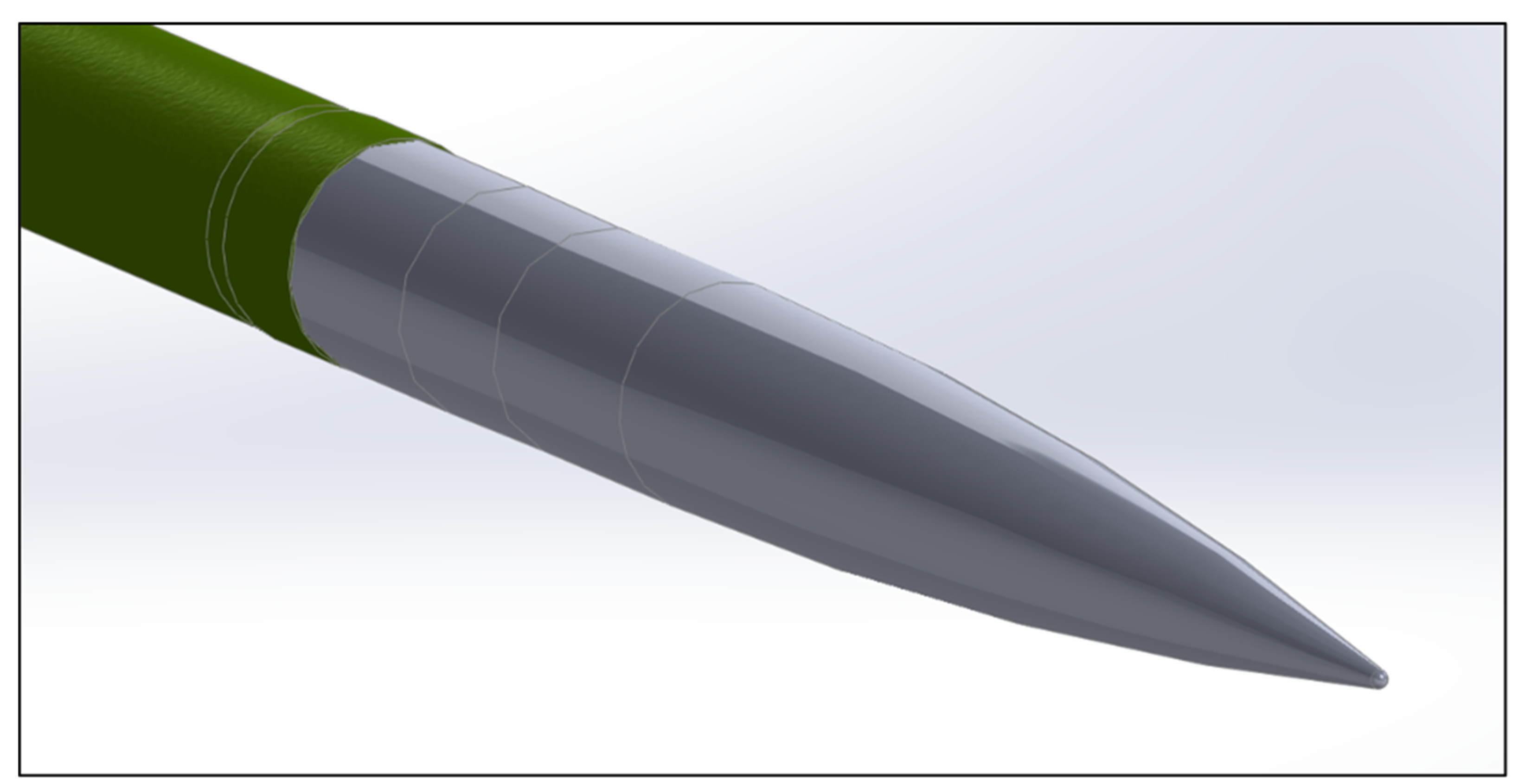
Finally, the above curve was implemented in the new version shown in Figure 4.

3.2. Determination of the Volume of the New Aerodynamic Contour in the Design Space for the Control System

The volume, as shown in Figure 5, of the rocket was determined by the space design for the control system actuators and related equipment. Therefore, the analysis was carried out only for the front part of the fuselage, excluding its nose section, i.e., Zone I, Figure 3. It should be noted that the telemetry antenna is mounted in Zone I; therefore, this component was not included in the analysis.
In the end, the following results were obtained: F n = 598,885   m m 2 and V n = 534,244   m m 3 .
The calculations enabled the determination of the new shape for the missile’s outer nose component. The developed outline was implemented into the design of the guided missile. Range tests confirmed that the new shape provides adequate space for the control system and improves aerodynamic parameters. Its accuracy was validated through comparison with test data, confirming its suitability for initial aerodynamic assessments.

4. Missile Aerodynamics Analysis

The innovative aspect of this work lies in applying analytical techniques in the early stage of aerodynamic design, which is rarely practiced in research projects. Earlier studies in this area have primarily relied on Computational Fluid Dynamics (CFD) to model aerodynamic properties. Carried out according to accepted standards and methods. In contrast, this project improved the front-end flow through a direct analytical approach from the outset. The fundamental aim of the project was to improve the aerodynamics of the rocket through changes to its physical structure, resulting in improved flight performance, increased structural efficiency, and increased internal volume. This process included, among other things, an analysis of the shape of the front of the rocket and its effect on distribution.
By applying innovative design solutions, it was possible to achieve tangible benefits in the form of reduced aerodynamic drag, which is key to increasing the rocket’s performance. The work also included an analysis of the impact on the stability and maneuverability of the rocket, which was important for its subsequent practical application. Prior to field testing, the above analyses were verified using semi-empirical methods using Digital DATCOM software Figure 6, as part of an ongoing project.
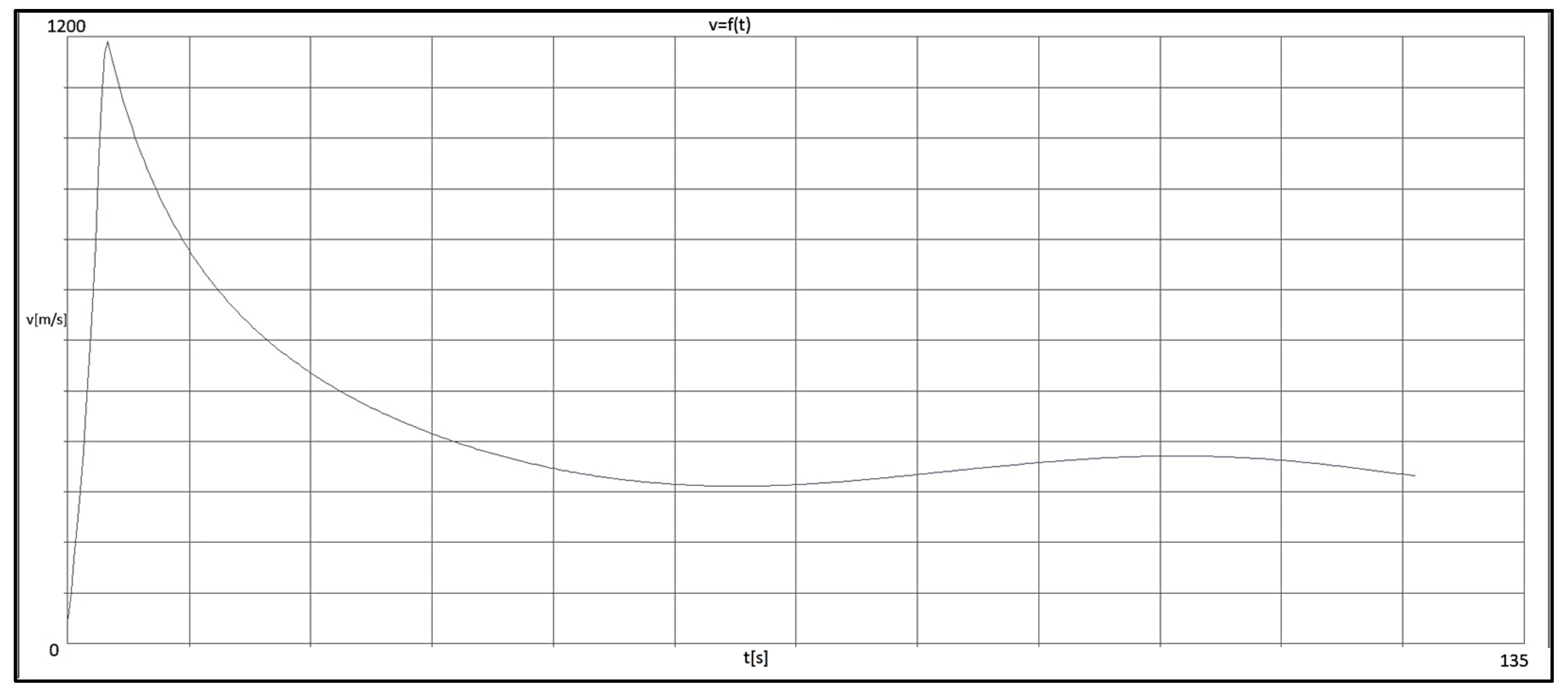
Figure 7 presents the velocity diagram of a rocket featuring a new aerodynamic flow designed through analytical methods.
The basic version was not tested, as its results were already established. A comparison between the semi-empirical results (Figure 7), the graph in Figure 8, and field test data confirmed consistency among the findings. These results confirm the effectiveness of the analytical method.
The rocket tests were conducted under atmospheric conditions characteristic of late afternoon, taking into account typical meteorological variations for this period.
  • Meteorological parameters:
  • Air temperature: 21.2 °C;
  • Atmospheric pressure: 1026 hPa;
  • Relative humidity: 65%;
  • Wind speed: 2.6 m/s (5 knots);
  • Wind direction: northeast (NE).
  • Initial rocket parameters:itial rocket parameters:
  • Rocket temperature: 20 °C;
  • Initial velocity: 300 m/s (according to engine specifications);
  • Launch angle: 55°.
  • Instrumentation and measurement methods:
Doppler Radar: Tracking the rocket’s flight path with a velocity measurement resolution of ±1 m/s; estimated velocity measurement uncertainty ±1.5%. Onboard Telemetry: Recording the rocket’s orientation with a sampling frequency of 100 Hz; angular measurement error below ±1.2°.
  • Data analysis:
Processing and analysis of the collected data employed Python 3.7, MATLAB R2018b, and Simulink tools, facilitating detailed modeling of flight dynamics, result analysis, and verification of the aerodynamic nose shape design.

5. Description of the Results

One of the central design modifications involved reshaping the rocket’s front section to enhance aerodynamic efficiency. The curve shown in Figure 3 was implemented into the new airflow line, providing sufficient internal spaciousness in the rocket’s structure, Figure 5 while improving its flight performance. This adjustment not only contributed to better in-flight stability, but also translated into improved targeting precision and reduced drag.
Modification of the shape of the missile’s nose section improved its speed and range, and reduced fuel consumption. During tests conducted on the training ground, the missile’s flight parameters were measured using a Doppler system. After analysis in Python 3.7 and processing the collected data, the results confirmed the positive effect of the modification on the missile’s flight parameters, such as speed, stability, and range.
The comparison of the missile’s speed in the previous version and the version with the new shape, presented in Figure 8, showed an increase in speed by approximately 5%. In Figure 8, the area of speed increase as a function of time from point A is simultaneously highlighted in gray. This increase in speed directly translates into an increase in the missile’s range, which significantly improves its operational effectiveness, especially in scenarios requiring precision strikes over long distances. The results allow the missile to be used in a variety of combat situations, making it more versatile, capable of performing a variety of tasks. Modifications to the missile’s front shape enhanced its flight stability and increased resistance to interference by reducing aerodynamic drag. The effect of this work improved its accuracy. Finally, the results of the analysis and field tests formed the basis for the decision to replace the nose section with a new one in the upgraded rocket. Thus, the replacements improved the aerodynamic properties of the missile and improved its flight performance. The modification process concerns not only the nose part of the rocket, but also other parts, so the rocket can be used for various combat missions.
Based on the positive results, the new modified shape will be implemented in future guided missile versions. This solution is an important step in the further development of Polish defense industry technologies.
The velocity–time graph of the rocket (Figure 8) shows an approximate 3–5% increase in maximum speed compared to the baseline version with the classic nose shape—the new maximum speed reaches about 1185 m/s, while the original was around 1145 m/s. This increase results from the modified aerodynamic shape that reduces the rocket’s frontal drag. The most significant speed difference occurs within the first 4 s of flight during the engine burn phase, after which the guided rocket maintains a higher velocity for a longer period, leading to an increased range.
Although detailed velocity data for other rocket variants are not presented here, this is due to the focus of testing on a single representative case that allowed for an effective evaluation of the impact of the modified nose shape on overall flight performance. Therefore, while additional data could provide supplementary insight, they were not necessary to validate the main conclusions. Consistent results from analytical, semi-empirical (DATCOM), and field tests confirm the reliability of these observations. During the last 20 s of the approximately 130 s flight, the rocket is under control and performs maneuvers. The observed increase in speed and range is realistic and justified, as only the nose geometry was modified, a reduction in the aerodynamic drag coefficient was confirmed, and the results were verified using multiple methods, including Doppler radar measurements. The higher initial velocity directly translates into improved combat effectiveness without negatively affecting the rocket’s stability and controllability.

6. Conclusions

The analysis of the optimal rocket nose shape was conducted to verify the initial design and identify potential improvements. Aerodynamic parameters were modified across four test sets (two pre-modification and two post-modification) to evaluate the rocket’s performance before and after the changes. For this project, most of the input data were already established, as it involved upgrading an existing rocket. Although this upgrade was less complex than designing a rocket from scratch, it still required a detailed analysis of the aerodynamic parameters to achieve maximum efficiency under the new operational conditions. Designing a new rocket from the ground up is more complex, as it requires determining key parameters such as the rocket diameter, planned nose length, flight speed, and other critical factors, as shown in Table 1. These values are crucial for the next stages of the design process because they directly influence the rocket’s aerodynamics and stability during flight.
The tests showed that after modification, the rocket’s range increased by approximately 3–5%. The post-modification rocket achieved a range of 44.3 km and 44.5 km at a launch angle of 55°. In comparison, the pre-modification rocket had a maximum range of 42 km, as shown in Table 2. The modification of the nose geometry was a significant factor in improving flight performance, particularly with respect to new operational requirements. Additionally, this change required shortening the rear section of the rocket, which affected the mass distribution and moments of inertia, but did not negatively impact the rocket’s stability during flight.
The 55° launch angle was selected as optimal for testing, as it provides the best compromise between range and flight stability. In general, for ballistic missiles, the maximum range is typically achieved at a launch angle of around 45°. However, in the case of guided missiles, which require greater precision and control over stability, a 55° launch angle ensures higher initial velocity while maintaining stability in flight. This angle was chosen to examine the performance of the rocket under realistic operational conditions, ensuring that the aerodynamic design modifications would perform effectively under a range of flight dynamics. The maximum value of 55° was included in Table 1, as it represents the highest tested angle and was crucial for obtaining a full understanding of the rocket’s flight characteristics across different trajectories.
Differences between the rockets (Missile 1 vs. Missile 2) may arise from natural variations in construction or measurement deviations. Changes in the nose geometry can also affect the mass distribution and moments of inertia, which in turn may alter ballistic parameters such as stability and flight trajectory. It is important to consider this to avoid misunderstandings when interpreting the results.
The modification of the rocket’s nose shape, which aimed to minimize the aerodynamic drag coefficient, directly influenced the mass distribution and moments of inertia. These changes affected key flight characteristics such as range and accuracy. While lengthening the nose section could potentially increase drag, the modified shape minimized this effect, leading to a reduction in drag and an increase in internal space for components such as the guidance systems. Proper management of the mass and inertia parameters further improved the rocket’s aerodynamic properties, as confirmed by both experimental tests and numerical simulations. Due to publication constraints, detailed drag coefficient values are not presented; however, minimizing this coefficient was a key objective of the modification. These results provide a solid foundation for further development, including the potential application of advanced numerical methods such as CFD simulations in subsequent project phases.

Author Contributions

Conceptualization, A.S. and R.G.; methodology, A.S.; software, A.S.; validation, A.S. and R.G.; investigation, A.S. and R.G. data curation, A.S.; writing—original draft preparation, A.S.; writing—review and editing, A.S. and R.G.; visualization, A.S.; supervision, R.G. All authors have read and agreed to the published version of the manuscript.

Funding

This research received no external funding.

Data Availability Statement

Data are contained within the article.

Conflicts of Interest

The authors declare no conflicts of interest.

References

  1. Budiyono, A.; Rachman, H. Proportional guidance and CDM control synthesis for a short-range homing surface–to–air missile. J. Aerosp. Eng. 2012, 25. [Google Scholar] [CrossRef]
  2. Hong, D.; Kim, M. Sungsu Park Study on reinforcement learning-based missile guidance law. Appl. Sci. 2020, 10, 6567. [Google Scholar] [CrossRef]
  3. Li, K.; Yang, S.; Zhao, L. Three-loop autopilot of spinning missiles. J. Aerosp. Eng. 2013, 228, 1195–1201. [Google Scholar] [CrossRef]
  4. Makowski, M.; Sienicki, K.; Motyl, K. Visualization of flight rocket missile in the environment Matlab/Simulink with the use of the Flightgear. Mechanik 2015, 7, 487–496. [Google Scholar] [CrossRef]
  5. Bużantowicz, W.; Pietrasieński, J. Dual-control missile guidance: A simulation study. J. Theor. Appl. Mech. 2018, 56, 727–739. [Google Scholar] [CrossRef]
  6. Dębecki, A.; Dubiel, S.; Konstrukcja Rakiet, C., III. Podstawy Projektowania Charakterystyki Aerodynamiczne i Optymalne Programy Lotu Rakiet; WAT: Warszawa, Poland, 1988. [Google Scholar]
  7. Szklarski, A.; Głębocki, R.; Jacewicz, M. Impact point prediction guidance parametric study for 155 mm rocket assisted artillery missile with lateral thrusters. Arch. Mech. Eng. 2020, 67, 31–56. [Google Scholar] [CrossRef]
  8. Zygmunt, B.; Motyl, K. Symulacja komputerowa balistyki 122 mm pocisku rakietowego ze zmodernizowanym zespołem napędowym. Probl. Mechatroniki Uzbroj. Lot. Inżyniera Bezpieczeństwa 2016, 7, 53–72. [Google Scholar] [CrossRef]
  9. Li, K.; Yang, S.; Zhao, L. Stability of spinning missiles with an acceleration autopilot. J. Guid. Control. Dyn. 2012, 35, 774–786. [Google Scholar] [CrossRef]
  10. Hu, S.; Wang, J.; Wang, Y.; Tian, S. Stability limits for the velocity orientation autopilot of rolling missiles. IEEE Access 2021, 9, 9504563. [Google Scholar] [CrossRef]
  11. Sreeja, S.; Hablani, H.B. Precision Munition Guidance and Moving Target Position Estimation. In Proceedings of the AIAA SciTech, AIAA Guidance, Navigation and Control Conference, Kissimmee, FL, USA, 5–9 January 2015. [Google Scholar]
  12. Xu, Y.; Wang, Z.; Gao, B. Six-degree-of-freedom digital simulation for missile guidance and control. Math. Probl. Eng. 2015, 2015, 829473. [Google Scholar] [CrossRef]
  13. Li, Z.; Dong, Q.; Zhang, X.; Zhang, H.; Zhang, F. Field-to-View Constrained Integrated Guidance and Control for Hypersonic Homing Intercepting Supersonic Maneuvering Targets. Aerospace 2022, 9, 640. [Google Scholar] [CrossRef]
  14. Trzun, Z.; Vrdoljak, M. Monte Carlo simulation of missile trajectories dispersion due to imperfectly manufactured warhead. In Proceedings of the 31st DAAAM International Symposium on Intelligent Manufacturing and Automation, Mostar, Bosnia and Herzegovina, 21–24 October 2020. [Google Scholar] [CrossRef]
  15. Wu, P.; Yuan, W.; Ji, L.; Zhou, L.; Zhou, Z.; Feng, W.; Guo, Y. Missile aerodynamic shape optimization design using deep neural networks. Aerosp. Sci. Technol. 2022, 126, 107640. [Google Scholar] [CrossRef]
  16. Şumnu, A.; Güzelbey, İ.H.; Öğücü, O. Aerodynamic Shape Optimization of a Missile Using a Multiobjective Genetic Algorithm. Int. J. Aerosp. Eng. 2020, 2020, 1528435. [Google Scholar] [CrossRef]
  17. Li, Y.; Yi, L.; Ao, Y.; Ma, L.; Wang, Y. Simulation analysis the aerodynamic characteristics of variable sweep wing missile. J. Phys. Conf. Ser. ICAACE 2020, 1570, 012073. [Google Scholar] [CrossRef]
  18. Kumar, R.; Mishra, P.R. Analysis of different shape of missile nose configuration. Int. J. Adv. Res. Innov. Ideas Educ. IJARIIE 2024, 10, 438–447. [Google Scholar]
Figure 1. Division of the missile into geometric sections.
Aerospace 12 00594 g001
Figure 2. Frontal shape of rockets for different speeds shown in dimensionless coefficients α and β .
Aerospace 12 00594 g002
Figure 3. Shape of a guided missile front after transition from dimensionless to denominated values.
Aerospace 12 00594 g003
Figure 4. Part of the front streamlining of the missile developed from the above analysis.
Aerospace 12 00594 g004
Figure 5. A schematic representation of the front part of the missile, which was used for the analysis of the volume and surface area of the shell.
Aerospace 12 00594 g005
Figure 6. Rocket model adopted for semi-empirical simulations.
Aerospace 12 00594 g006
Figure 7. Graph of rocket velocity v = f(t).
Aerospace 12 00594 g007
Figure 8. Comparison of the flight speed of a ballistic Missile 1 with a new version of a guided Missile 1.
Aerospace 12 00594 g008
Table 1. Data on the missile obtained from the literature. The value ranges presented in the Table (e.g., 70 ÷ 120, 10 ÷ 55) have been deliberately given as numerical intervals, since parameters such as flight time, launch angle, or range depend on specific mission conditions—particularly on the distance to the target and the selected flight trajectory.
Missile Flight Characteristics ValuesPhysical Units
Flight time to target t l 70 ÷ 120 s
Length of the missile L 2671 m m
Caliber Φ 0.1 m
Angle of throw α p 10 ÷ 55 °
Launch mass of the missile m 62.6 k g
Initial velocity v p o c z 290 m / s
Maximum flight speed v m a x 1375 m / s
Coordinate of the position of the center of mass at the time of launch x 0 p 1679 m m
Coordinate after fuel burnout x 1 p 1656 m m
Range x 28 ÷ 42 k m
Table 2. Comparison of missile range and velocity before and after nose shape modification.
Test SetLaunch Angle (°)Range (km)Max. Velocity (m/s)
Missile 1 (pre-modification) 55 ° 41.9 1145
Missile 1 (post-modification) 55 ° 44.5 1185
Missile 2 (pre-modification) 55 ° 41.4 1135
Missile 2 (post-modification) 55 ° 44.3 1190
Disclaimer/Publisher’s Note: The statements, opinions and data contained in all publications are solely those of the individual author(s) and contributor(s) and not of MDPI and/or the editor(s). MDPI and/or the editor(s) disclaim responsibility for any injury to people or property resulting from any ideas, methods, instructions or products referred to in the content.