Abstract
The autonomous landing of unmanned aerial vehicles (UAVs) on moving platforms has potential applications across various domains. However, robust landing remains challenging because the detection reliability of UAVs decreases when the UAV is close to a moving platform. To address this issue, this paper proposes a novel landing strategy that ensures a high detection rate. First, a robust detectable region was established by considering the sensing range and maneuverability limitations of the UAV. Second, a vector field was designed to guide the UAV to the moving platform while remaining in a robust detectable region. Next, safe and accurate landings were achieved by considering the current velocity and vector field. The landing strategy was validated through outdoor flight experiments. A quadrotor equipped with a gimbal-mounted camera was used, and a fractal marker was attached to the moving platform for detection and tracking. When the moving platform moved at a speed of 2–4.3 m/s, the UAV successfully landed on the platform with a distance error of 0.4 m. Because of the robust detectable region and vector field, the detection was conducted with a high success rate (94.9%).
1. Introduction
Advancements in autonomous techniques for unmanned aerial vehicles (UAVs) have extended their application to various fields, such as search and rescue, military, agriculture, surveillance, inspection, and transportation [1,2]. Particularly, the integration of UAVs with computer vision has led to remarkable developments in UAV autonomy [3,4]. For example, vision-based autonomous landing enhances the potential for cooperation between UAVs and other vehicles. However, autonomous landing on moving platforms remains challenging due to various factors such as environmental disturbances, model uncertainties, and detection failures [5,6].
Several issues hinder reliable landing on moving platforms, including a limited sensor field-of-view (FoV), perspective distortion, gimbal angle constraints, perception delay, wind-induced disturbances, and the unpredictable motion of moving platforms. These issues become more severe when the UAV altitude decreases during landing. All issues except disturbances are directly related to detection failures. To mitigate such failures, previous studies used fish-eye lenses [7] and gimbal-mounted cameras [8,9]. Although fish-eye lenses offer a wide FoV, significant image distortion caused by the lenses lowers the localization accuracy. Gimbal cameras can stabilize images during agile maneuvers and continuously track dynamic platforms. The tracking motion of the gimbal effectively reduces the likelihood of the moving platform exiting the FoV of the camera.
Another research area associated with vision-based landing is occlusion-robust fiducial markers for platform detection. Although widely used fiducial markers, such as ArUco3 [10] and AprilTag3 [11], can be easily implemented, they may fail in detecting the markers when occlusion occurs. To address this problem, fractal-structured markers have been developed because they can maintain robust detection even in partially occluded scenarios [12].
Perception delay is unavoidable in vision-based autonomous landings owing to the sequential processes of image capture, data transmission, and computational processing [13]. Furthermore, it is difficult to accurately and quickly estimate unpredictable platform dynamics. Under these conditions, robust perception or control approaches alone may prove insufficient in landing applications, and a decision-making layer is necessary to select a robust landing strategy. Within a decision-making framework for adaptive landing, temporarily ascending to regain visibility during platform acceleration is more effective at preventing detection failures than continuing the descent.
Trajectory optimization and model predictive control are widely used for landing control. Because these approaches are beneficial when considering constraints, they have been adopted to incorporate limitations associated with visual detection into optimal controls [14,15,16]. However, because of the limited computational resources of quadrotor platforms, solving nonlinear optimization problems with nonlinear constraints in real time is extremely challenging, particularly at low altitudes, where considerable computational latency and replanning caused by disturbances can cause landing failure.
To overcome these limitations, this paper proposes a novel landing strategy that accounts for detectability while minimizing the computational burden. First, detectability, defined as the ability to visually track the landing platform when the UAV approaches, is guaranteed. Factors influencing detectability include system constraints such as the FoV of the camera, gimbal angle range, and perspective effects, and external factors such as occlusion, perception delay, and unknown motion. To realize robust landing, it is essential to maintain high detectability at high and low altitudes. Hence, a robust detectable region (RDR) was defined, within which reliable visual tracking is guaranteed. Subsequently, a vector field was designed to guide the quadrotor toward the landing platform. Because vector fields are computationally lightweight, they can be executed using a real-time onboard landing controller. Furthermore, vector fields naturally inherit robustness to disturbances through closed-loop behavior [17]. In this study, a quadrotor was used as the UAV, and a gimbal camera was employed to enlarge the RDR. A fractal marker was attached to the moving platform for visual localization.
The main contributions of this study are as follows:
- RDR: This new region was determined to ensure consistent detectability for moving platforms by considering the sensor and quadrotor constraints.
- Vector field for landing: This vector field ensures that the quadrotor remains with the RDR and successfully lands on the platform while considering the mobility constraints of the quadrotor.
- Real-world validation: The proposed landing strategy was empirically verified through extensive outdoor experiments involving dynamically moving platforms.
The rest of this paper is organized as follows: Section 2 describes the derivation of the RDR. Section 3 presents the design of the vector field, its stability analysis, and the admissible set from the perspective of quadrotor acceleration. Section 4 presents the experimental results obtained from a real-world flight test. Section 5 discusses the results obtained using the proposed landing approach, and Section 6 presents the conclusions drawn from this study.
2. Robust Detectable Region
2.1. Reference Frames and Relative Position Representation
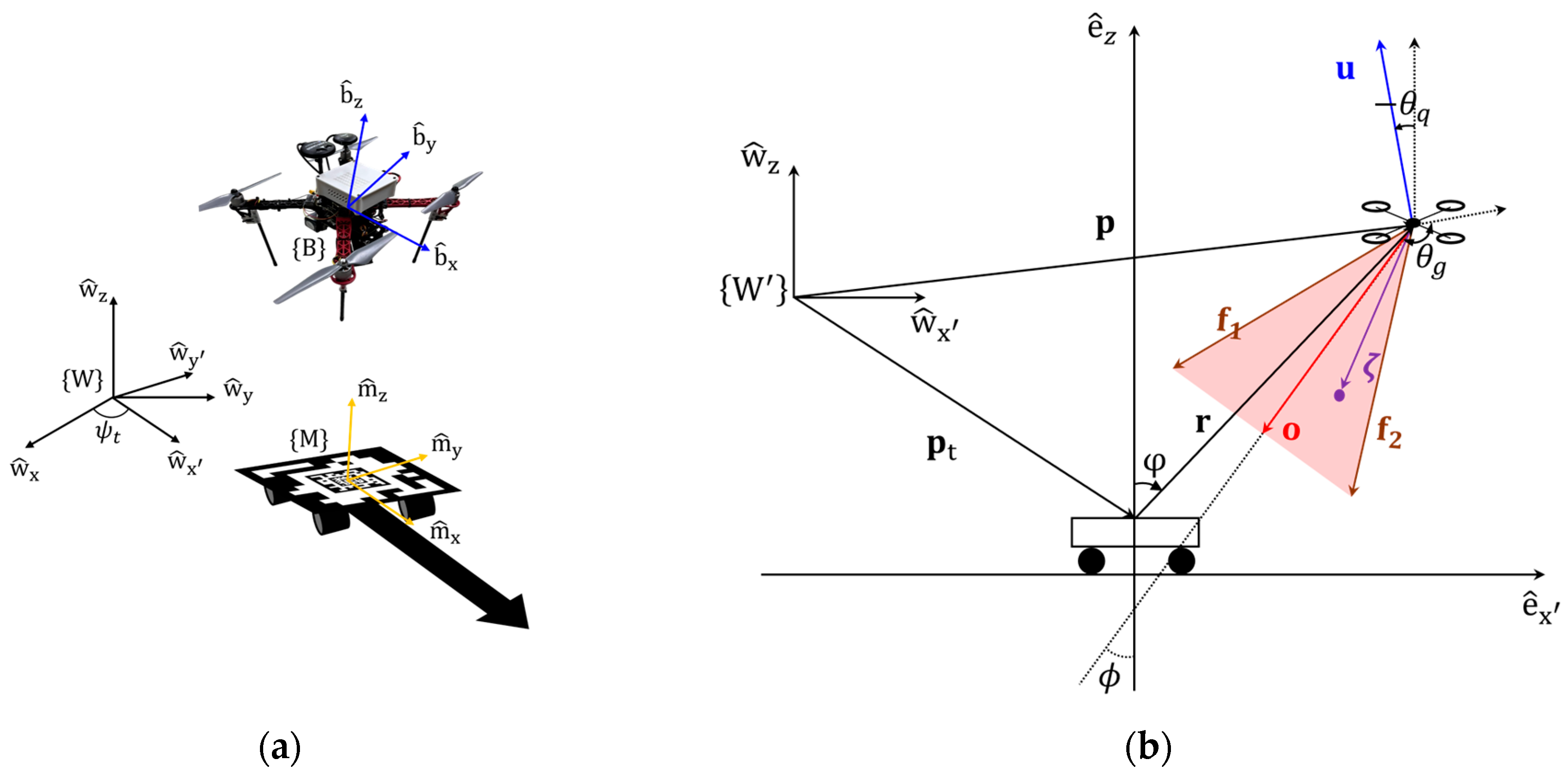
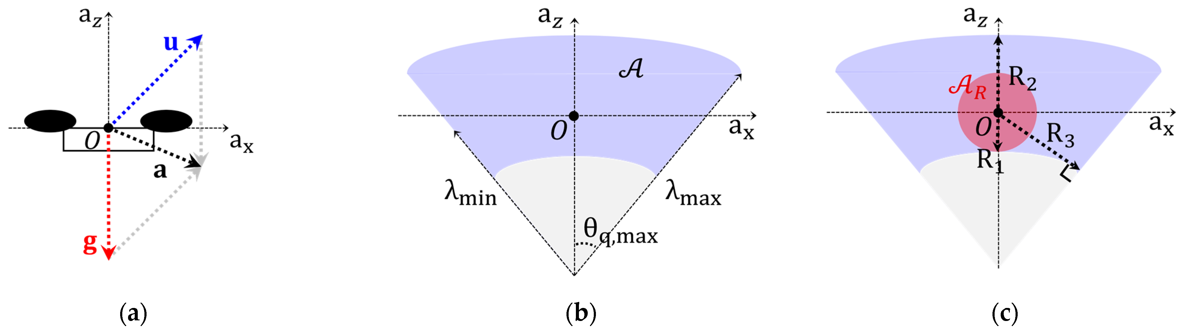
To describe the RDR, the world frame, body frame of the quadrotor, and marker frame of the moving platform are denoted as and , respectively, as shown in Figure 1a. The x, y, and z axes of the frame are denoted as and , respectively. The axes of the other frames are denoted similarly, as shown in Figure 1a. The angle between and is denoted by and is referred to as the reference heading angle.

Figure 1.
(a) Overview of frames; (b) simplified scenario in longitudinal-vertical plane.
For simplicity, it is assumed that the frames of the camera and gimbal coincide with the frame of the quadrotor body, a condition that can generally be established using the Kalibr toolbox to calibrate the inertial measurement unit (IMU) and camera [18].
If the heading directions of the quadrotor and moving platform are aligned, the positions can be described as shown in Figure 1b. The positions of the quadrotor and fiducial marker are denoted as and , respectively. Their relative positions can be represented as . The position of the quadrotor can also be considered with a polar coordinate as follows: . The thrust force vector is obtained as , where is the pitch angle of the quadrotor, and is the thrust magnitude. The tilt angle of the gimbal is denoted as .
The camera FoV can be considered as an isosceles triangle in two-dimensional space [19,20]. Consider a vector starting from the quadrotor and pointing to a point in the FoV of the camera. The vector can be represented as , where vectors and are defined as and , respectively, as shown in Figure 1b. and satisfy relationships , , and , where is the maximum detection range. If the vector spans opposite direction of the relative position vector , then moving platform exists within the FoV of the camera. The unit vector of an optical axis can be obtained as .
2.2. Visible Region and Marker Detectable Region
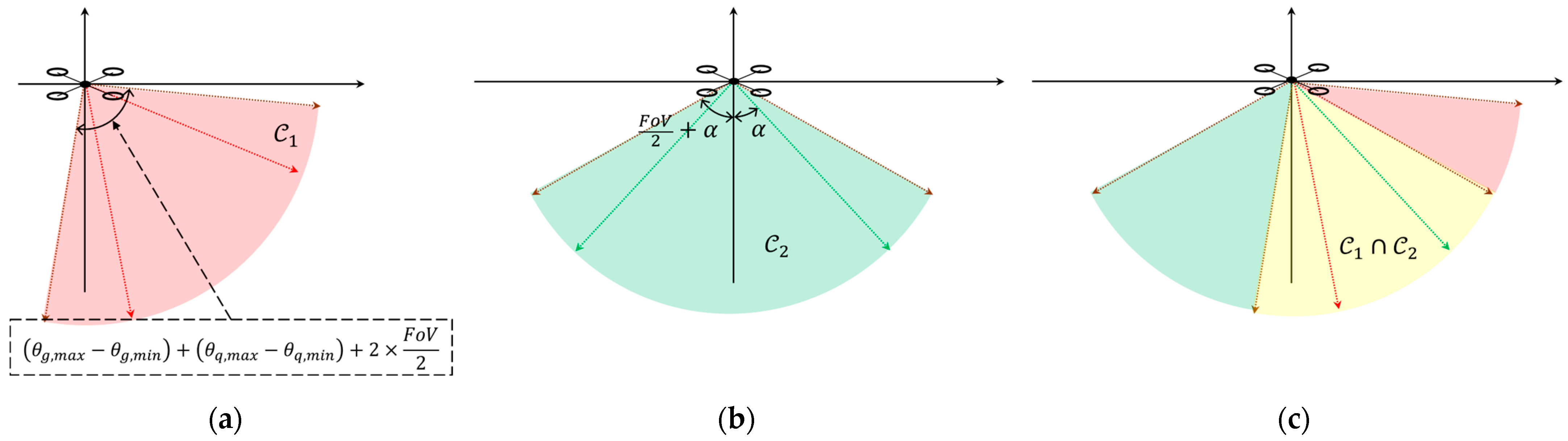
Because the pitch angle of the quadrotor is controlled to compensate for external disturbances such as wind, the detection quality can vary depending on the external disturbance. Thus, a conservative visible region was introduced. If the platform exists in region , it remains in the FoV of the quadrotor camera as long as the pitch angle of the quadrotor is within the predefined range. However, depending on the perspective distortion and the detection algorithm, detection can fail. Thus, a more conservative detectable region is needed to consider the detection performance of the detection algorithm. Since the detection quality of the fiducial marker varies depending on the orientation of the fiducial marker, it can be represented in the fiducial marker frame. Then, the region needs to be represented in the (quadrotor) body frame to merge it with the region . Because and are independent of each other, they can be separately defined and then be combined to find .
Regions and are defined to consider the kinematic constraints of the quadrotor and gimbal, as follows:
- : the visible region, which is the intersection of the union of all FoVs when the gimbal moves in its angle limit and the union of all FoVs when the quadrotor tilts in its pitch angle. These regions are illustrated in Figure 2a.
 Figure 2. (a) Visible region; (b) detectable region; (c) intersection of regions.
 - : the marker detectable region, where the marker can be detected with high probability. Here, is the angle between the optical axis and normal vector of the fiducial marker; is the angle at which the detection performances of the fiducial marker start to decrease steeply; and denotes the signum function. These regions are shown in Figure 2b.
The FoV, gimbal angle range mechanical constraints, and pitch range of the quadrotor tilt angle constraints were considered to determine . These constraints should be considered owing to quadrotor dynamics. The quadrotor must be tilted forward to accelerate in the forward direction. This tilting motion prevents the quadrotor from detecting the moving platform. Therefore, by considering the pitch constraints of the quadrotor, the platform can be detected even during agile maneuvers.
Here, the should be considered because the detectability of fiducial markers is primarily influenced by the angle between the optical axis and the normal vector of the fiducial marker [21,22,23]. Previous studies have shown that the detection accuracy and rate remains high if the marker exists within region through simulation [21] and real-world validations [22,23].
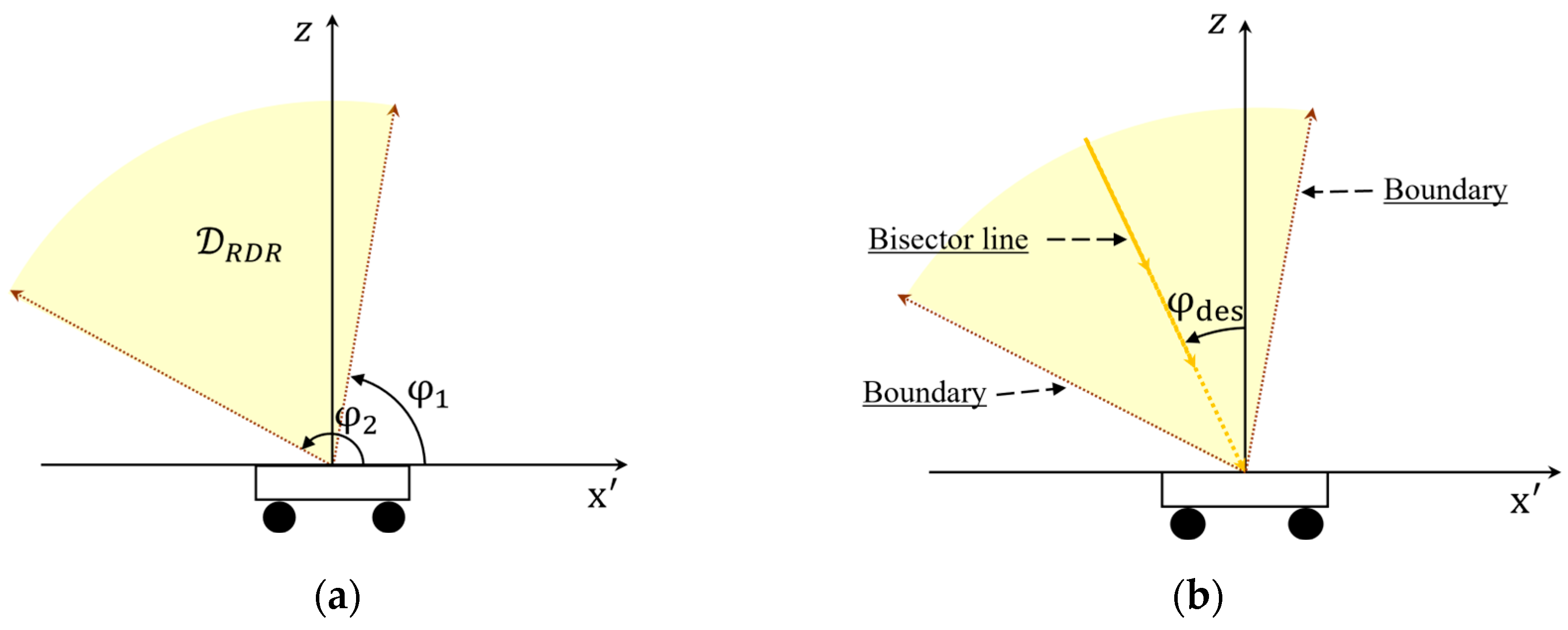
The moving platform can be detected by the quadrotor while it exists within the intersection shown in Figure 2c. This intersection can also be represented from the platform perspective, as shown in Figure 3a. This transformed region is defined as the RDR, as follows:
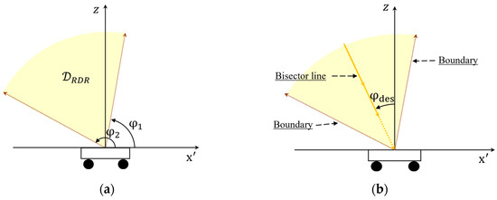
Figure 3.
(a) Platform referenced robust detectable region (RDR); (b) reference bisector line and boundaries of RDR.
If the quadrotor remains in the RDR, it can detect a moving platform. Thus, robust and autonomous landing can be realized by guiding the quadrotor to the landing point while remaining within the RDR. Specifically, a vector field was designed to guide the quadrotor along the bisector line, as shown in Figure 3b. The relationship between the and coordinates is modeled as follows:
The RDR can also be represented with polar coordinates as follows:
where , and . As long as the quadrotor exists in , the quadrotor system is robust in the perspective of visual tracking.
3. Region-Based Vector Field for Quadrotor Landing Guidance
This section presents the vector field designed to guide a quadrotor to land on a moving platform. A stability analysis and a reduced admissible set are also presented to demonstrate that the proposed vector field satisfies the conditions of the RDR.
3.1. Vector Field Design
The quadrotor position relative to the moving platform can be represented in polar coordinates as , where , and is the angle of the bisector line, as shown in Figure 3b. A new vector field for landing was developed as follows:
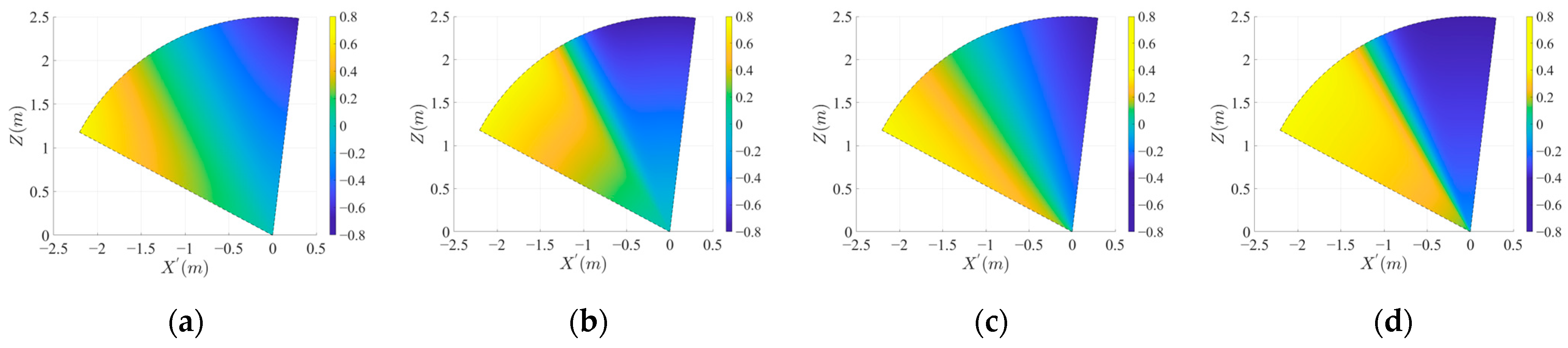
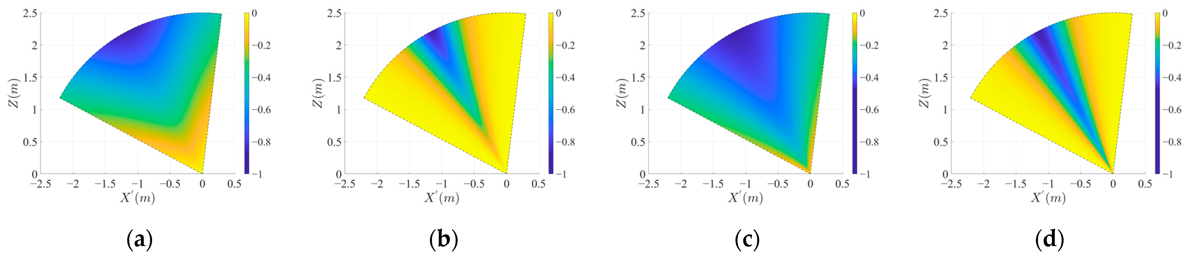
where and are the vector field parameters. The vector field is shown in Figure 4a. When the quadrotor approaches the boundary of the RDR, it may move out of the RDR owing to practical issues such as perception or response delays. A quadrotor can descend despite being far from the bisector line. In both cases, landing failures may occur. Therefore, the vector field is divided into two side regions and a central region, as shown in Figure 4b. Particularly, the vector field guides the quadrotor toward the central region when it is located in the side region. When the quadrotor entered the central region, it was guided to move in a radial direction for landing. Thus, the tangential velocity toward the bisector line was high in the side regions and low in the central region. The radial velocity was high in the central region and low in the side regions. The central and side regions can be divided by the tangential critical angle and radial critical angle . Once the critical angles are determined, parameters and can be obtained by solving and .
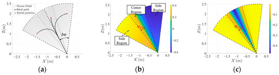
Figure 4.
(a) Proposed vector field and trajectories of three initial positions; (b) tangential velocity map of vector field; (c) radial velocity map of vector field. The dashed lines represent the boundary between the center and side regions.
The term in Equation (4) suppresses rapid quadrotor motion when it approaches the moving platform and encourages faster movement at longer distances to enhance tracking performance.
The vector field can be modified effectively by adjusting the tangential and radial critical angles. As shown in Figure 5a–d, decreasing allows the quadrotor to converge toward the bisector line before reaching the landing point. Because the bisector line provides the highest robustness within the RDR, decreasing enhances the overall robustness. Excessively small values induce oscillations near the bisector line. The makes the convergence order of the vector field obvious by suppressing the radial velocity in the unsafe region. As shown in Figure 6a–d, the range of angles at which the quadrotor descends becomes clear as decreases.
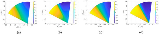
Figure 5.
Vector field map of tangential component: (a–d) represents map when , , and , respectively.
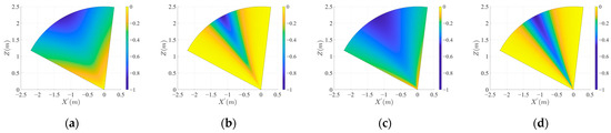
Figure 6.
Vector field map of radial component: (a–d) represents map when , , and , respectively.
Notably, a vector field lacking term exhibit certain limitations. First, prolonged hovering at low altitudes is undesirable because the RDR is significantly smaller near the landing surface. Second, when the quadrotor approaches the moving platform, the vector magnitude becomes extremely small, resulting in excessively slow landing. To address these limitations, a fractional power function was incorporated into the vector field design. As the parameter in Equation (4) increases, the tangential and radial velocities at low altitudes increase, as shown in Figure 5c,d and Figure 6c,d. This means that the ability to attract the bisector line and maintain radial velocity is enhanced at low altitudes.
3.2. Convergence Analysis and Reduced Admissible Set
To ensure that the quadrotor can stably land on the moving platform, it must be shown that a quadrotor operating within the RDR under the guidance of the vector field described by Equation (4) converges to the landing point at . To establish this convergence, the following lemmas are first demonstrated:
Lemma 1.
A quadrotor operating in the RDR and guided by the vector field expressed by Equation (4) will converge to the equilibrium point .
Proof of Lemma 1.
Let be a continuously differentiable Lyapunov candidate function defined as follows:
where . Because the equilibrium point for the system presented in Equation (4) is , is positive definite and bounded. The time derivative of can be obtained as follows:
Because this is negative definite, the system is asymptotically stable at the equilibrium point of RDR. □
To realize this vector-field guidance, the quadrotor must follow the vector field defined by Equation (4). This can be accomplished using the acceleration control law [24], expressed as follows:
where is a positive gain.
Lemma 2.
The acceleration control law defined by Equation (7) ensures that asymptotically converges to the vector field expressed by Equation (4).
Proof of Lemma 2.
Let be a continuously differentiable error Lyapunov candidate function defined as follows:
where is the difference between the quadrotor velocity and the desired velocity provided in the vector field. is positive definite and bounded. The time derivative of can be obtained as follows:
By substituting Equation (7) into Equation (9), the time derivate of can be calculated as follows:
Because this is negative semi-definite, the tracking error is asymptotically stable at the origin of the RDR. □
According to Lemma 1, the quadrotor converges to the landing point when it moves along the vector field. Additionally, according to Lemma 2, it can follow the vector field asymptotically. Therefore, the quadrotor operating within the RDR and controlled according to the proposed vector field will converge asymptotically to the landing point .
The achievable accelerations of the quadrotor are limited by the physical constraints and can be characterized by the following admissible set:
where is the actual control acceleration vector; is the gravity vector; and is the total acceleration, which is zero when the quadrotor hovers. Again, and represent the thrust and pitch angle of the quadrotor. Figure 7a shows the relationships between , , and . The admissible set is shown in the blue region in Figure 7b.
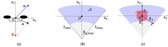
Figure 7.
(a) The blue dotted line represents the actual control acceleration vector generated by the rotor thrust, the red dotted line indicates the gravity vector , and the black dotted line indicates the total acceleration vector . The quadrotor moves with the acceleration of ; (b) admissible set ; (c) reduced admissible set when .
Then, a reduced admissible set can be defined as follows:
The radii , , and are three distances from the origin to the boundaries, as shown in Figure 7c. The system is robust with respect to the dynamic limitations of the quadrotor, provided that the quadrotor acceleration remains within the reduced admissible set. In this case, the reduced admissible set, highlighted in red, corresponds to condition .
To control the quadrotor while considering its thrust and pitch angle constraints, the acceleration command expressed by Equation (7) should belong to a reduced-admissible set. Because the reduced admissible set is created as a circle centered at the origin in the acceleration space, as shown in Figure 7c, the upper bound of the acceleration command should be less than . The upper bound of can be derived as follows:
If the relative velocity of the quadrotor to the moving platform is assumed to be , the bound of the vector field magnitude can be calculated as follows:
where , and is the maximum radius from the landing point. Subsequently, the time derivative of the vector field can be obtained as follows:
where is the Frobenius norm of the Jacobian matrix. Theoretically, tends to infinity at if . However, owing to the landing gear, the value of is not zero, even when the quadrotor lands. Therefore, has a positive lower bound (that is, ). Then, is bounded in this radial range, and thereby can be bounded. Then, the upper bound of can be determined as follows:
If , the acceleration command always belongs to the reduced admissible set. Therefore, if , the acceleration command satisfies the pitch and thrust constraints. Again, is the upper bound of the relative velocity, and . The value of can be obtained as follows:
4. Experimental Results
Several real-world experiments were conducted to validate the performance of the proposed landing strategy. The supplementary video can be found at: https://www.youtube.com/watch?v=uzD8aMVH_I4 (accessed on 30 May 2025). A Robot Operating System (ROS) package used in this study is available at: https://github.com/bwh1270/vector_field_landing (accessed on 30 May 2025).
4.1. Experimental Setup
4.1.1. Hardware Specifications
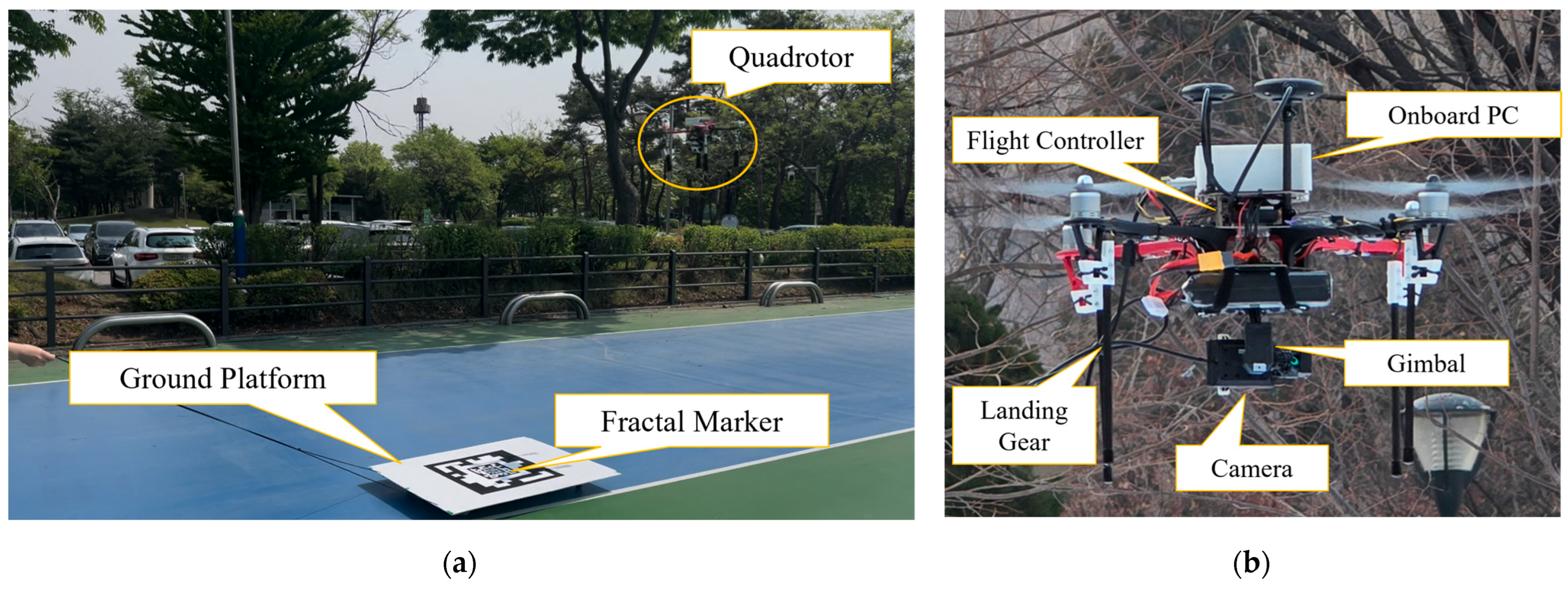
A customized quadrotor and moving platform were developed to validate the proposed landing strategy in the real world. The moving platform comprised a wheeled base, A0-sized white foam board, and cm2 fractal marker, as shown in Figure 8a. A 5-layer fractal marker configuration (5L6) was used because this configuration is robust against occlusions and suitable to autonomous landing tasks [25]. As shown in Figure 8b, the quadrotor was built using a DJI F450 frame, equipped with a Holybro Pixhawk4 flight controller running the PX4-Autopilot firmware [26]. The landing gear of the quadrotor was constructed from lightweight carbon fiber tubes and equipped with a noise-damping interlayer pad to absorb impact forces during landing. For accurate quadrotor positioning, both the M9N GPS and KASS GNSS modules were integrated. High-level functionalities were executed using ROS on an NVIDIA Jetson Xavier NX board. A Tarot T4-3D gimbal was used to control the orientation of the camera. Visual tracking of the moving platform is performed using the Arducam Global Shutter USB camera (B0332), which captures monochromatic images at a resolution of 800 600. The Tarot gimbal can operate in its full range since the Arducam camera (69 g) is lighter than the GoPro HERO3, which is the recommended camera for the gimbal. The overall weight of the quadrotor system was 2.01 kg. The gimbal angle range, camera FoV, and pitch range of the quadrotor are presented in Table 1.
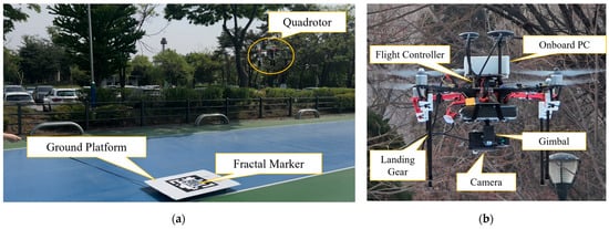
Figure 8.
(a) Quadrotor and moving platform; (b) quadrotor hardware.

Table 1.
System constraints.
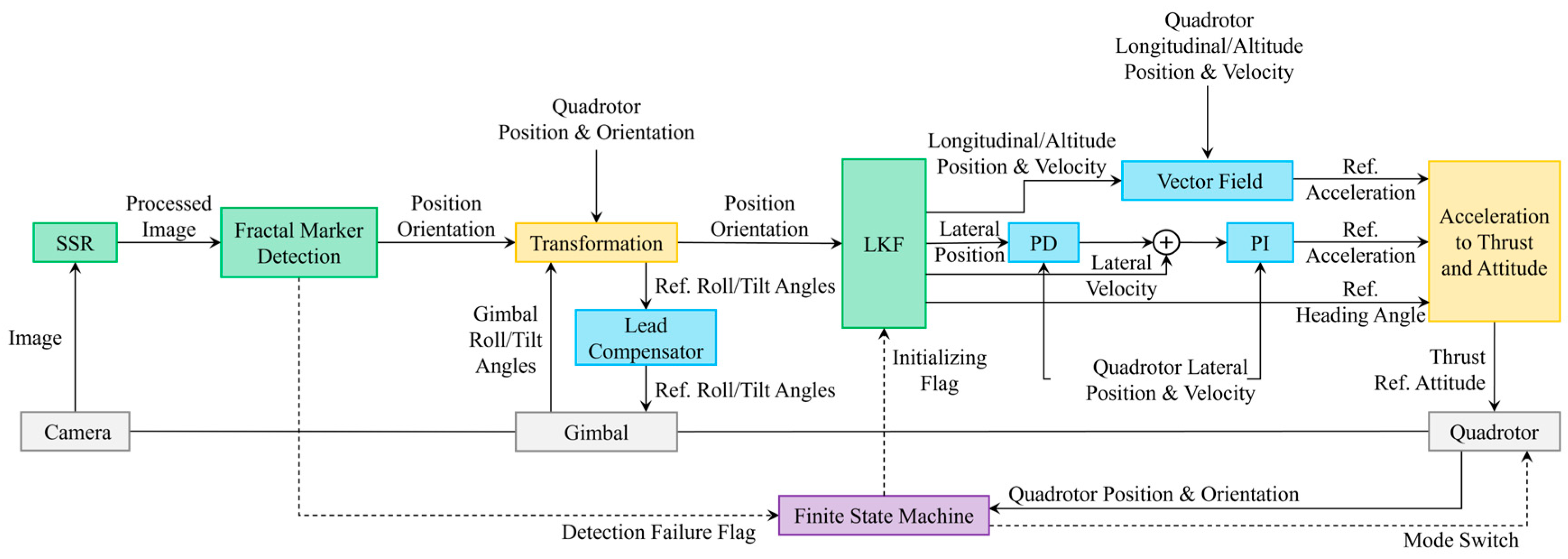
4.1.2. System Architecture
An overview of the system architecture is presented in Figure 9. The fractal marker detection module requires the longest computation time. The maximum loop rate that the onboard system can sustain was approximately 40 Hz. Because the vector field is computationally efficient, the full landing algorithm could be used at a 40 Hz loop rate without additional delay.
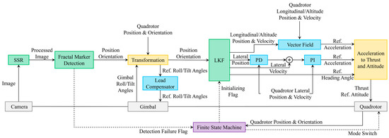
Figure 9.
Block diagram of quadrotor system.
Images were captured at approximately 40 Hz, and a single-scale retinex (SSR) was applied for illumination correction. This preprocessing effectively mitigates the detection failures caused by the shadow of the quadrotor at low altitudes. The preprocessed image is transmitted to the next module, along with a timestamp indicating the image capture time. This time stamp was used to synchronize various signals, including the gimbal angle, quadrotor pose, and fractal marker detection results. The perception delay was approximately 0.07 s.
By considering the gimbal angles and quadrotor attitude, the relative positions of the fractal marker and quadrotor can be represented by the world frame. The gimbal angle was controlled using a lead compensator to track the marker on the moving platform.
The velocity of the moving platform was estimated using a linear Kalman filter (LKF) based on a constant velocity model. The estimated velocity was decomposed into longitudinal and lateral components, which were fed into the vector field generator and lateral controller, respectively. Then, the reference acceleration command and heading angle of the ground platform were used to compute the thrust and desired attitude commands for the quadrotor. The mission stages, ranging from search to final landing, were coordinated using a finite-state machine to achieve full autonomy.
The position estimation error of the fractal marker is very small (less than 10 cm), and the yaw measurement of the gimbal is inaccurate. Thus, the estimation error about the platform position can be large when the gimbal rotates about its yaw axis. However, since the platform moves along a straight path in the experiments and LKF compensates for the sensor measurement errors, the effects of position estimation errors on the landing were not considerable.
4.2. Vector Field Parameters
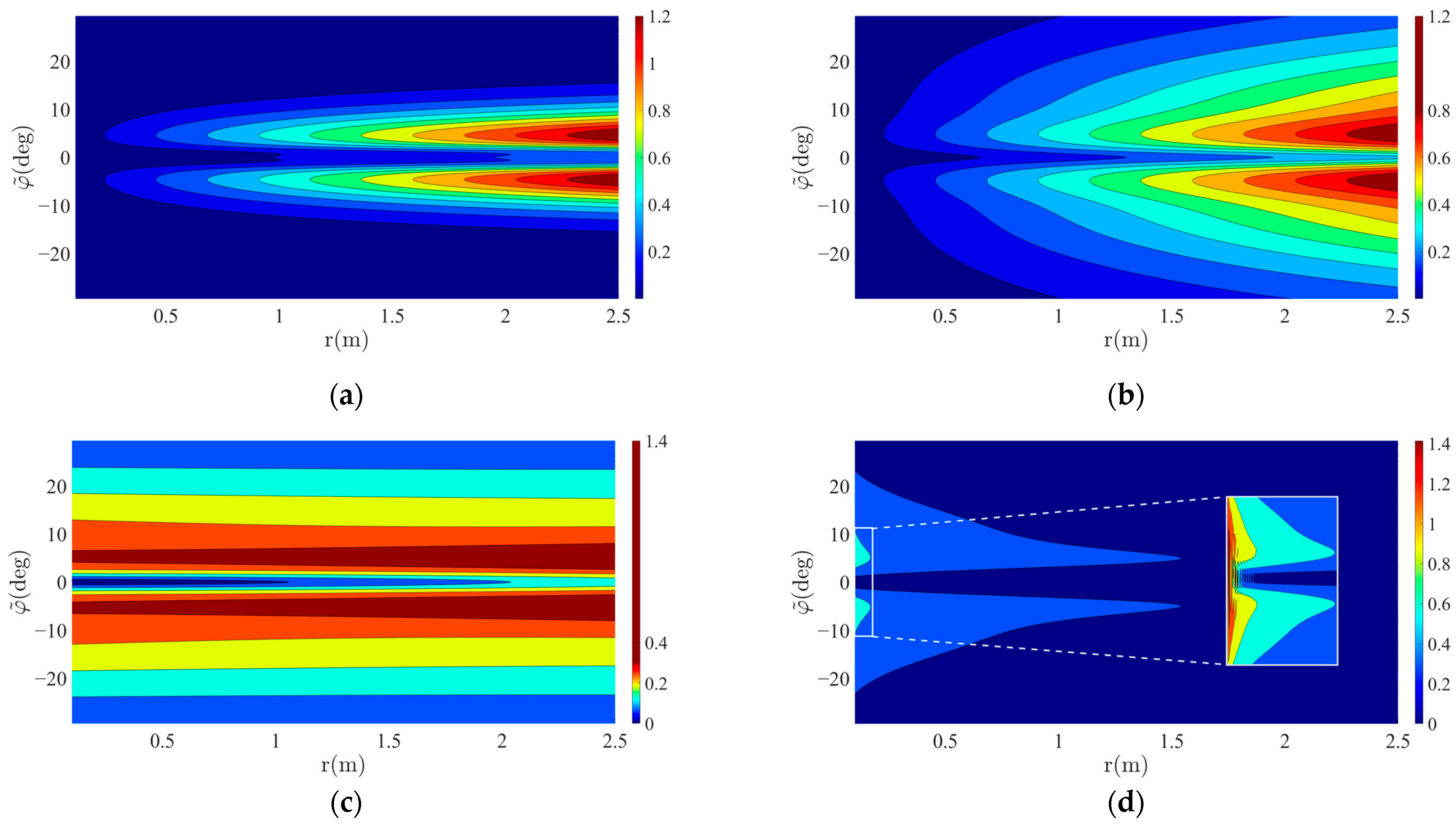
The vector field was determined by the design parameters and gain parameters . As mentioned in Section 3.1, can be obtained from the tangential critical angle that discerns the center and side region of the vector field. If this angle is too large, the quadrotor is excited at the RDR boundary in the presence of a considerable delay. If is extremely small, then it can oscillate near the bisector line. As the critical angle decreases, the quadrotor is more likely to remain in the RDR, which is particularly important at low altitudes. This study empirically determined the critical angle by reducing it until the quadrotor did not oscillate at low altitudes.
The value of can be calculated from the radial critical angle , which determines where the radial velocity begins to increase exponentially. If the critical angle is determined to be the same as the critical angle used in , the center and side regions can be clearly distinguished. However, a rapid acceleration change occurs, as shown in Figure 10a. Consequently, a large oscillation can occur owing to the sudden acceleration change (jerk). Therefore, in this study, the critical angle was set to be larger than that used for . Figure 10b shows a smooth acceleration profile, with a noticeable reduction in peak acceleration.
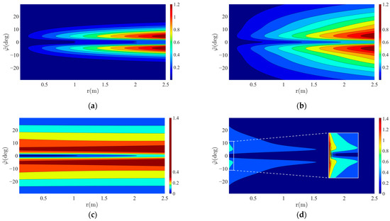
Figure 10.
Acceleration contour of vector field: (a) when , that is, the critical angle used in is equal to the critical angle used in ; (b) when , that is, the critical angle used in is larger than the critical angle used in ; (c) when ; (d) when .
While a larger value of n improves landing speed, it adversely affects the smoothness of acceleration transitions. Nonetheless, a large n is advantageous, as a smaller n leads to slow speed at low altitudes, increasing the risk of the quadrotor exiting the RDR. However, when n is very large, the acceleration variation at low altitudes increases, as shown in Figure 10c,d. Significant changes in acceleration were observed at extremely low altitudes. This suggests that a very large value of n also makes landing challenging. Hence, the value of n was set to 2 in this study.
The gain parameters were empirically determined to ensure that the acceleration command remained within the reduced admissible set and that the velocity magnitude did not exceed the vector field bound expressed by Equation (14). The parameters of the vector field are listed in Table 2.
Table 2.
Vector field parameters.
4.3. Simulation Results
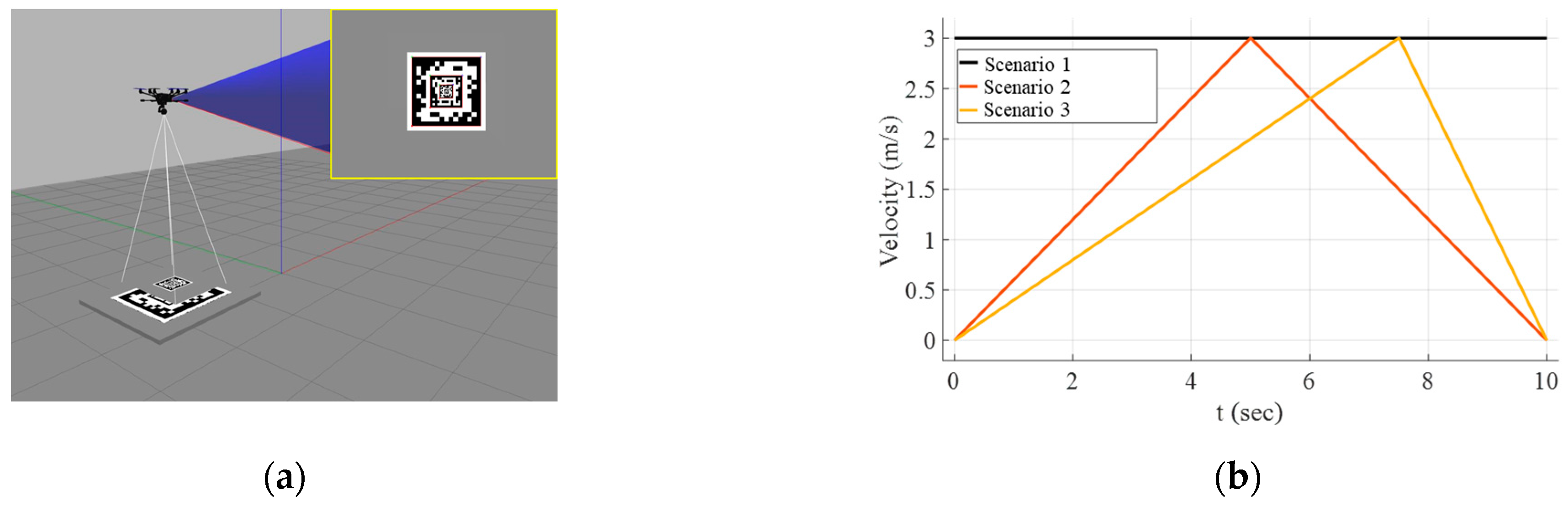
To verify the proposed method, its landing performance was compared with a baseline method in Gazebo simulation, as shown in Figure 11a. The forward motion of the baseline method was controlled by feedforward control [27]. The desired value of the descending velocity was set to 0.2 m/s in the baseline method. Then, the descending velocity is controlled using a PID controller to track the desired speed.
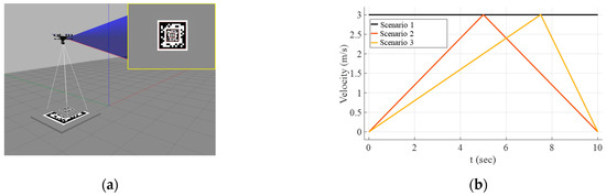
Figure 11.
Simulation environments: (a) gazebo simulator; (b) velocity profiles of the ground platform.
The drone model used in the simulation is the Typhoon h480 used in [26]. The camera resolution is chosen at 800 600 resolution. The tilt angle of the gimbal ranges from −90 to 45. The landing performances were compared in three different scenarios, as shown in Figure 11b. Results were obtained both without sensor delay and with a 0.02-s delay.
The proposed method showed a higher landing success rate than the baseline, as provided in Table 3. In scenario 1, which is the easiest scenario, landings were successful in all trials for both the baseline and proposed methods. Whereas the proposed method can also land the quadrotor successfully in scenario 2, detection failures frequently took place in the baseline method. Moreover, landing failed in every trial when the perception delay was added. Finally, in scenario 3, the baseline method is never able to land with or without the perception delay. The detection failures were observed when the ground platform rapidly decelerated. Meanwhile, the proposed method can land in scenario 3 because it considered the physical constraints of the system. These results indicate that the proposed method enables robust landing even when sudden changes occur in the platform motion.
Table 3.
Comparison of the landing performance.
4.4. Outdoor Experimental Results
To validate the performance of the proposed vector field-based landing strategy, several real-world experiments were conducted with the platform moving at zero, low, and high speeds.
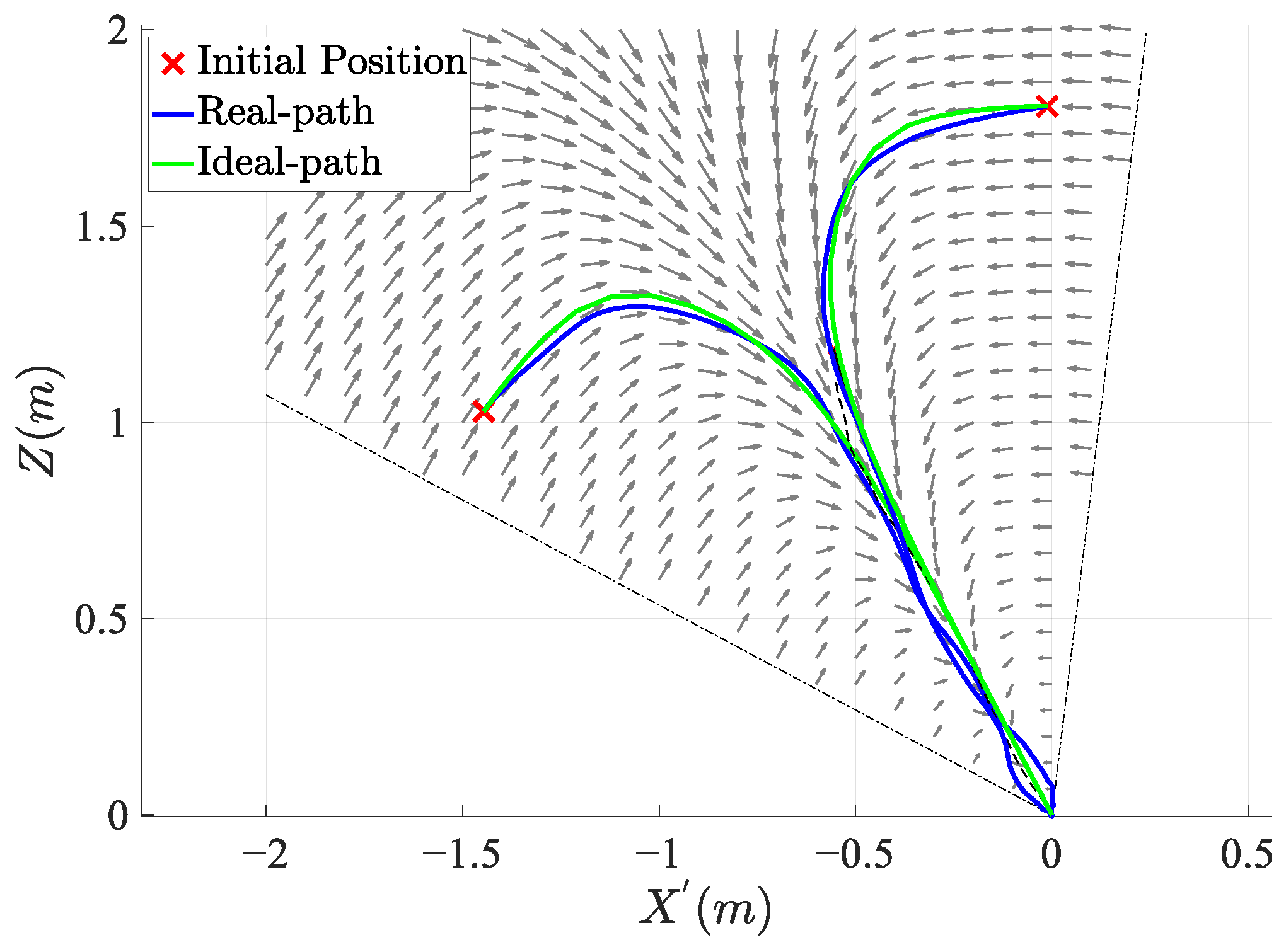
Figure 12 shows the trajectories of the quadrotor for three different initial positions when landing on a stationary platform. The ideal paths that moved perfectly along the vector field were compared with the trajectories observed in the actual flights. These results reveal that the quadrotor reliably converges to the landing point regardless of its initial position.
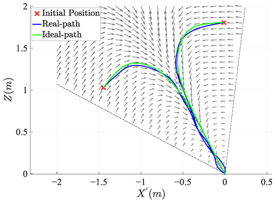
Figure 12.
Comparison between ideal and actual trajectories from three initial conditions in the static platform scenario. The arrows represent velocity vectors created by the vector field.
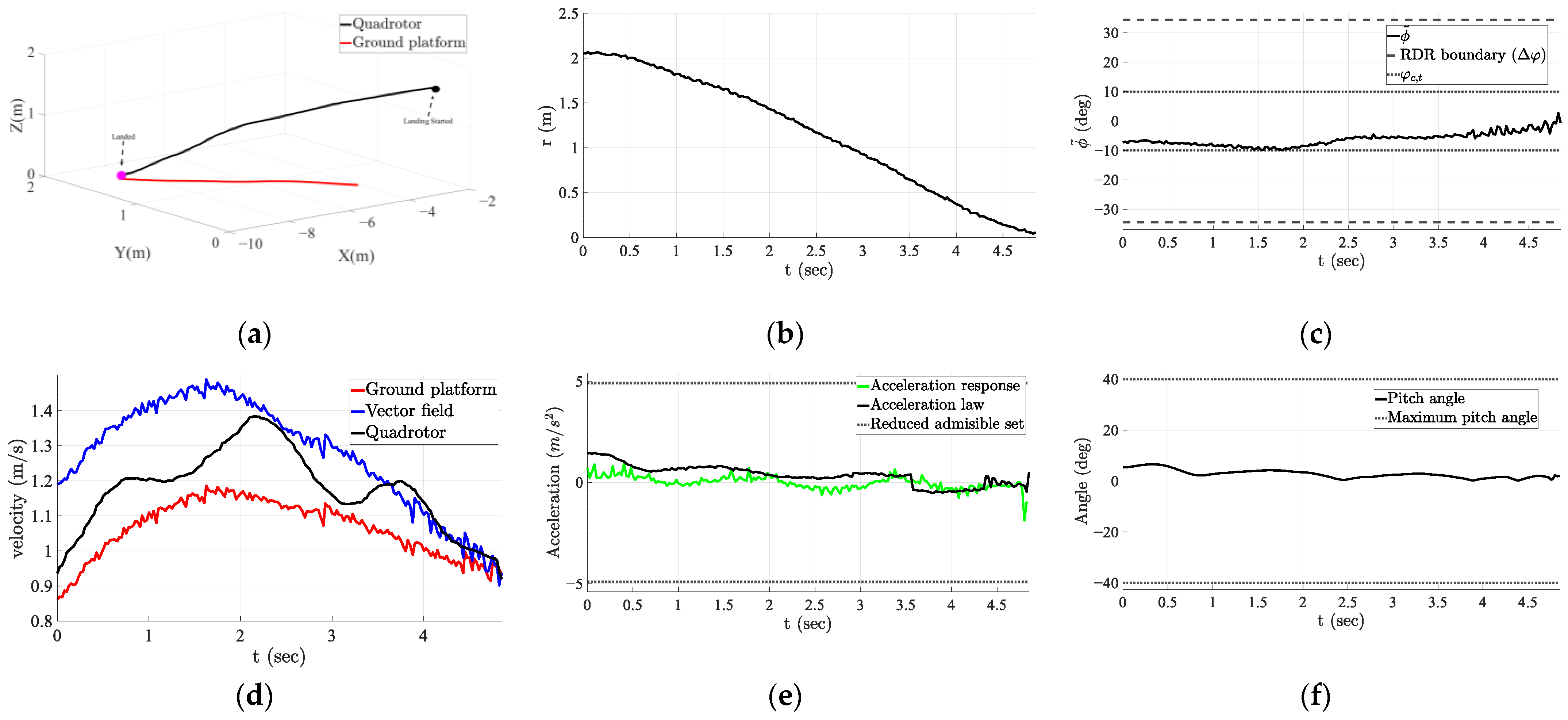
The landing results obtained when the platform moved at low velocity are presented in Figure 13. The distance to the platform and the angle to the bisector line steadily decreased, as shown in Figure 13b,c. A lag in the longitudinal velocity response was observed at the beginning, as shown in Figure 13d. Consequently, the angle to the bisector line increased during this interval. At the same interval, the acceleration of the ground platform was observed. After acceleration, the quadrotor was successfully aligned with the bisector line and converged at the landing point. Figure 13e shows that the acceleration command remained within the reduced admissible set, verifying Equation (16). The actual acceleration closely tracks the command with a delay of less than 0.5 s. Consequently, the pitch angle remained within the maximum pitch range of the quadrotor, as shown in Figure 13f.
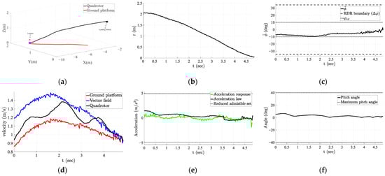
Figure 13.
Landing results obtained with low-speed platform: (a) 3D landing trajectory; (b) distance from quadrotor to platform; (c) angle to bisector line; (d) proceeding velocities; (e) acceleration law and response; (f) pitch angle profile.
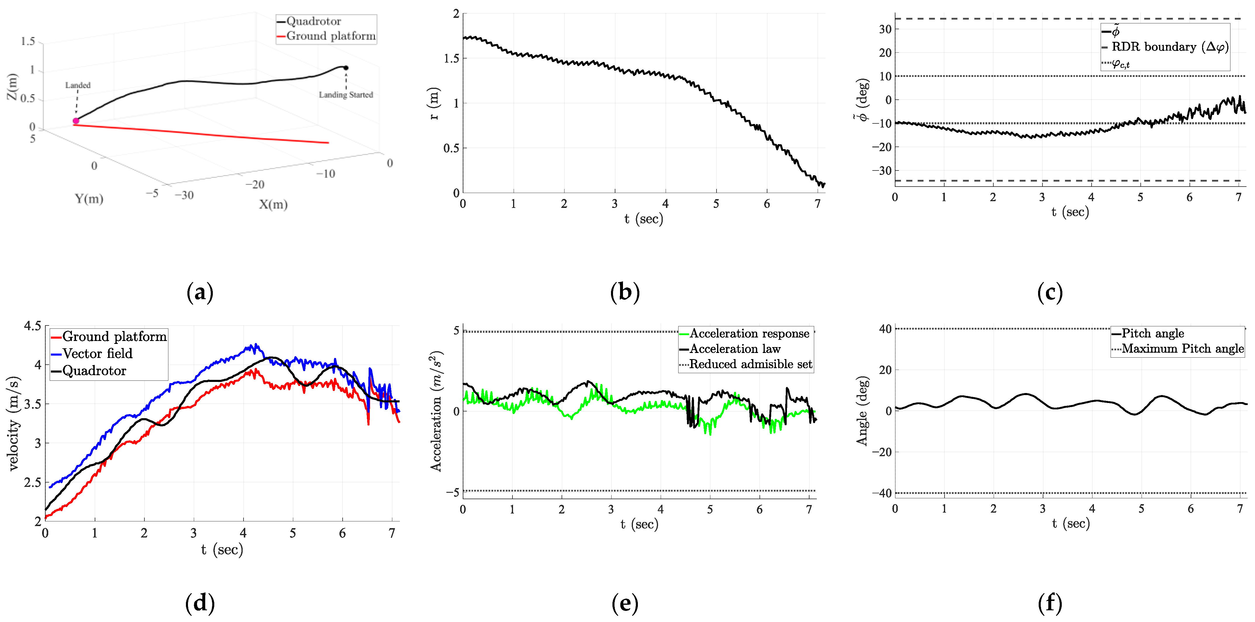
When the platform moved at high speeds, more complicated dynamics were observed, as shown in Figure 14. Initially, the ground platform moved with high accelerations. Consequently, the quadrotor was driven away from the center region of the RDR. Then, the quadrotor was controlled to move from the side region to the center region and reduced its descent velocity by the vector field. Due to this motion, detection failure can be prevented. As a result, the quadrotor stayed at the boundary between the center and side regions until the ground platform acceleration decreased. Once the platform velocity stabilized, the quadrotor rapidly descended toward the landing point while aligning itself with the bisector line. Even in this scenario, the generated acceleration command remained within the reduced admissible set. Therefore, the pitch angle constraints were not violated, as shown in Figure 14e,f. Additionally, the quadrotor acceleration cannot track the acceleration command due to the delay, as shown in Figure 13e and Figure 14e. Moreover, the error in the acceleration was increased with the platform speed.

Figure 14.
Landing results obtained with high-speed platform: (a) 3D landing trajectory; (b) distance from quadrotor to the platform; (c) angle to bisector line; (d) proceeding velocities; (e) acceleration law and response; (f) pitch angle profile.
Figure 13b and Figure 14b show that the descent speed at low altitudes was maintained as mentioned in Section 3.1. The proposed acceleration command enabled the quadrotor to follow the vector field with small errors, as shown in Figure 13d and Figure 14d. The control system showed its robustness in the perspective of RDR and acceleration. First, the quadrotor constantly existed in the RDR during the tracking flight, as shown in Figure 13c and Figure 14c. Second, the acceleration command remains in the reduced admissible set, as shown in Figure 13e and Figure 14e. These results indicate that the developed controller can maintain robustness, at least when the ground platform speed is below 4.3 m/s.
The quantitative performances are summarized in Table 4. Five trials were conducted for each platform speed. The landing distance error was calculated using the Euclidean distance between the final position of the quadrotor and the center of the fractal marker. The detection success rate indicates how the platform can be detected during each trial. This performance metric was measured to quantitatively verify the effects of RDR on detectability. It is defined as the ratio of the number of frames where the marker was successfully detected to the total number of frames acquired during the trial. Note that the platform was moved along a straight path. The detection success rate was high in all scenarios, validating the effects of the RDR. The detection success rate decreased slightly as platform speed increased. The detection success rate was reduced primarily by the illuminations caused by the shadow of the quadrotor, even though the image preprocessing method of SSR was applied. As a result, some detection failures occurred even for stationary platforms.
Table 4.
Detection and landing performances with different platform speeds.
In all trials, the 450-size quadrotor successfully landed on the platform with a small distance error (less than 0.4 m), which was clearly caused by the platform speed. The mean value of the error decreased by approximately 1.7 to 4.1 times as the platform velocity increased.
These results confirm that remaining within the RDR is important for a successful landing. Moreover, the proposed vector field-based landing strategy provides a robust landing capability at different platform speeds.
5. Discussion
This study mathematically proved the convergence of the quadrotor to the landing point in the RDR. Thus, the initial conditions were also sampled in the RDR. The parameters of the vector field can be adjusted according to the motions of the ground platform. When the ground platform moves with an irregular velocity change, the rotational vector field gain should be larger to maintain the quadrotor within the central region. In addition, as the platform velocity increases, the gains of the vector field γ should be increased to enhance tracking performance.
Outdoor experiments were conducted up to the maximum speed at which the ground platform can be steered along a straight path. It is expected that successful landing can be achieved on a platform with higher speeds by increasing the gain γ until the sensor noise is significantly amplified by the large gain value. The distance error at landing would increase considering the error trends provided in Table 4.
A key observation is that setting the vector field parameter to a large value introduces noticeable oscillations. Although a larger enables faster descending motion at lower altitudes, it also leads to abrupt acceleration changes. Therefore, must be carefully tuned to balance landing speed and jerk smoothness.
The outdoor experiments were conducted in a windy outdoor environment where trees were even shaking. Due to the wind disturbance, the quadrotor velocity was slowly fluctuating over time, as shown in Figure 13d and Figure 14d. The proposed vector field-based landing theoretically guarantees convergence of the quadrotor to the landing point. One can argue that the landing may fail in real-world experiments if external disturbances, noise, and delays are significant. It is obvious that these factors increase the tracking control error. However, if the disturbing factors are not strong enough to push the quadrotor outside the RDR, successful landing is still possible due to sustained detection.
The quadrotor successfully landed on the moving platform without detection failure in outdoor flight tests, even when the platform moved with relatively large acceleration. In some challenging cases, the quadrotor failed to follow the ideal vector field trajectory. The primary reason for this is the inaccurate and delayed estimation of platform velocity. This limitation was particularly evident in scenarios where the quadrotor approached the platform faster than the estimated platform speed, as presented in Table 4. In these cases, the quadrotor temporarily lost tracking of the ground platform and exited the RDR owing to unreliable velocity estimations at low altitudes.
The stability of the vector field can be maintained, provided the position and velocity of the platform are accurately estimated. Hence, improved velocity estimation is essential for landing on fast-moving platforms. Moreover, the relative height estimation between the quadrotor and the moving platform is affected by measurement noise and perception delay. For example, the quadrotor occasionally failed to detect a successful touchdown, even after the landing gear came into contact with the platform. This is attributed to imprecise height measurements near the final approach. To address this issue, a threshold-based termination condition was introduced: the quadrotor motors shut down when the relative height between the landing gear and the platform drops below 5 cm. This rule ensures the reliable recognition of landing completion despite sensing uncertainties.
6. Conclusions
This paper proposes a robust landing strategy for quadrotor-targeting moving ground platforms, addressing critical challenges related to detectability under physical limitations and disturbances. One of the main contributions of this study is the identification of the RDR, which ensures high detectability throughout the flight. A vector field-based control approach was developed to guide the quadrotor within this region without violating the requirements of the RDR.
The proposed strategy was implemented using a gimbal-mounted monocular camera and an occlusion-robust fractal marker. Real-world experiments revealed that the quadrotor consistently achieved high detection success rates and precise landings. Even when the platform moved with high acceleration, the system achieved consistent landings. When the distance between the quadrotor and the platform rapidly increases due to high acceleration of the platform, the quadrotor is guided to the central region and decreases its descending velocity. This control strategy prevents detection failures that may result from high platform acceleration. These results verify the theoretical foundation and practical robustness of the RDR and vector field approach.
Future work will primarily focus on improving the estimator for accurate moving platform velocity estimation and developing a compensator for perception and response delays. To this end, a vector field-based planning strategy and observer-based robust control approaches are considered.
Author Contributions
Conceptualization, W.B. and W.N.; methodology, W.B., S.H., H.J. and S.L. (Seokwon Lee); software, W.B. and S.Y.; validation, H.J., S.Y. and S.L. (Seokwon Lee); investigation, W.B., S.H., H.J., S.Y. and S.L. (Sungwon Lim); resources, S.L. (Seokwon Lee); data curation, W.B. and S.Y.; writing—original draft preparation, W.B. and W.N.; writing—review and editing, W.B., S.L. (Seokwon Lee) and W.N.; visualization, W.B. and S.L. (Sungwon Lim); supervision, W.N.; project administration, W.N.; funding acquisition, W.N. All authors have read and agreed to the published version of the manuscript.
Funding
This research was supported by the National Research Foundation of Korea (NRF) Grant funded by the Korea Government [Ministry of Science and ICT (MSIT)] under Grant 2023R1A2C1006655, RS-2025-02214162, and the Chung-Ang University Graduate Research Scholarship in 2023.
Data Availability Statement
The data presented in this study are available on request from the corresponding author. The data are not publicly available due to security and privacy concerns regarding sensitive flight location and operational information.
Conflicts of Interest
The authors declare no conflicts of interest.
References
- Elmokadem, T.; Savkin, A.V. Towards fully autonomous UAVs: A survey. Sensors 2021, 21, 6223. [Google Scholar] [CrossRef] [PubMed]
- Patrinopoulou, N.; Lappas, V.; Daramouskas, I.; Meimetis, D.; Kostopoulos, V. Autonomy in UAV Civilian Applications. In Autonomous Vehicles-Applications and Perspectives; IntechOpen: London, UK, 2023. [Google Scholar]
- Kanellakis, C.; Nikolakopoulos, G. Survey on computer vision for UAVs: Current developments and trends. J. Intell. Robot. Syst. 2017, 87, 141–168. [Google Scholar] [CrossRef]
- Al-Kaff, A.; Martin, D.; Garcia, F.; de la Escalera, A.; Armingol, J.M. Survey of computer vision algorithms and applications for unmanned aerial vehicles. Expert Syst. Appl. 2018, 92, 447–463. [Google Scholar] [CrossRef]
- Xin, L.; Tang, Z.; Gai, W.; Liu, H. Vision-based autonomous landing for the uav: A review. Aerospace 2022, 9, 634. [Google Scholar] [CrossRef]
- Bhargavapuri, M.; Shastry, A.K.; Sinha, H.; Sahoo, S.R.; Kothari, M. Vision-based autonomous tracking and landing of a fully-actuated rotorcraft. Control Eng. Pract. 2019, 89, 113–129. [Google Scholar] [CrossRef]
- Kim, J.; Jung, Y.; Lee, D.; Shim, D.H. Landing control on a mobile platform for multi-copters using an omnidirectional image sensor. J. Intell. Robot. Syst. 2016, 84, 529–541. [Google Scholar] [CrossRef]
- Borowczyk, A.; Nguyen, D.-T.; Nguyen, A.P.-V.; Nguyen, D.Q.; Saussié, D.; Le Ny, J. Autonomous landing of a quadcopter on a high-speed ground vehicle. J. Guid. Control Dyn. 2017, 40, 2378–2385. [Google Scholar] [CrossRef]
- Zhang, Y.; Wu, Z.; Wei, T. Aerodynamic Disturbance Estimation in Quadrotor Landing on Moving Platform via Noise Reduction Extended Disturbance Observer. IEEE Sens. J. 2024, 24, 37566–37574. [Google Scholar] [CrossRef]
- Romero-Ramirez, F.J.; Muñoz-Salinas, R.; Medina-Carnicer, R. Speeded up detection of squared fiducial markers. Image Vis. Comput. 2018, 76, 38–47. [Google Scholar] [CrossRef]
- Wang, J.; Olson, E. AprilTag 2: Efficient and robust fiducial detection. In Proceedings of the 2016 IEEE/RSJ International Conference on Intelligent Robots and Systems (IROS), Daejeon, Republic of Korea, 9–14 October 2016; pp. 4193–4198. [Google Scholar]
- Romero-Ramire, F.J.; Muñoz-Salinas, R.; Medina-Carnicer, R. Fractal markers: A new approach for long-range marker pose estimation under occlusion. IEEE Access 2019, 7, 169908–169919. [Google Scholar] [CrossRef]
- Guo, Z.; Yang, J.; Li, S.; Wang, Z. Robust Visual Landing Control of Quadrotor on a Moving Platform: A Sampled-Data Approach With Delayed Output and Disturbances. IEEE Trans. Control Syst. Technol. 2024, 32, 2283–2297. [Google Scholar] [CrossRef]
- Maniatopoulos, S.; Panagou, D.; Kyriakopoulos, K.J. Model predictive control for the navigation of a nonholonomic vehicle with field-of-view constraints. In Proceedings of the 2013 American Control Conference, Washington, DC, USA, 17–19 June 2013; pp. 3967–3972. [Google Scholar]
- Mohamed, I.S.; Allibert, G.; Martinet, P. Sampling-based MPC for constrained vision based control. In Proceedings of the 2021 IEEE/RSJ International Conference on Intelligent Robots and Systems (IROS), Prague, Czech Republic, 27 September–1 October 2021; pp. 3753–3758. [Google Scholar]
- Snobar, F.; Reinhard, J.; Huber, H.; Hoffmann, M.; Stelzig, M.; Vossiek, M.; Graichen, K. FoV-based model predictive object tracking for quadcopters. IFAC-PapersOnLine 2022, 55, 13–18. [Google Scholar] [CrossRef]
- Gonçalves, V.M.; McLaughlin, R.; Pereira, G.A. Precise landing of autonomous aerial vehicles using vector fields. IEEE Robot. Autom. Lett. 2020, 5, 4337–4344. [Google Scholar] [CrossRef]
- Zhang, X.; Fang, Y.; Zhang, X.; Jiang, J.; Chen, X. A novel geometric hierarchical approach for dynamic visual servoing of quadrotors. IEEE Trans. Ind. Electron. 2019, 67, 3840–3849. [Google Scholar] [CrossRef]
- Penin, B.; Giordano, P.R.; Chaumette, F. Vision-based reactive planning for aggressive target tracking while avoiding collisions and occlusions. IEEE Robot. Autom. Lett. 2018, 3, 3725–3732. [Google Scholar] [CrossRef]
- Wang, Q.; Gao, Y.; Ji, J.; Xu, C.; Gao, F. Visibility-aware trajectory optimization with application to aerial tracking. In Proceedings of the 2021 IEEE/RSJ International Conference on Intelligent Robots and Systems (IROS), Prague, Czech Republic, 27 September–1 October 2021; pp. 5249–5256. [Google Scholar]
- Kallwies, J.; Forkel, B.; Wuensche, H.-J. Determining and improving the localization accuracy of AprilTag detection. In Proceedings of the 2020 IEEE International Conference on Robotics and Automation (ICRA), Paris, France, 31 May–31 August 2020; pp. 8288–8294. [Google Scholar]
- Kalaitzakis, M.; Cain, B.; Carroll, S.; Ambrosi, A.; Whitehead, C.; Vitzilaios, N. Fiducial markers for pose estimation: Overview, applications and experimental comparison of the artag, apriltag, aruco and stag markers. J. Intell. Robot. Syst. 2021, 101, 71. [Google Scholar] [CrossRef]
- Jurado-Rodriguez, D.; Muñoz-Salinas, R.; Garrido-Jurado, S.; Medina-Carnicer, R. Planar fiducial markers: A comparative study. Virtual Real. 2023, 27, 1733–1749. [Google Scholar] [CrossRef]
- Lawrence, D.A.; Frew, E.W.; Pisano, W.J. Lyapunov vector fields for autonomous unmanned aircraft flight control. J. Guid. Control Dyn. 2008, 31, 1220–1229. [Google Scholar] [CrossRef]
- Anikin, D.; Ryabinov, A.; Saveliev, A.; Semenov, A. Autonomous landing algorithm for UAV on a mobile robotic platform with a fractal marker. In Proceedings of the International Conference on Interactive Collaborative Robotics, Baku, Azerbaijan, 25–29 October 2023; pp. 357–368. [Google Scholar]
- Meier, L.; Honegger, D.; Pollefeys, M. PX4: A node-based multithreaded open source robotics framework for deeply embedded platforms. In Proceedings of the 2015 IEEE International Conference on Robotics and Automation (ICRA), Seattle, WA, USA, 26–30 May 2015; pp. 6235–6240. [Google Scholar]
- Yi, J.; Lee, D.; Park, W.; Byun, W.; Huh, S.; Nam, W. Autonomous Control of UAV for Proximity Tracking of Ground Vehicles with AprilTag and Feedforward Control. In Proceedings of the 2023 International Conference on Unmanned Aircraft Systems (ICUAS), Warsaw, Poland, 6–9 June 2023; pp. 349–353. [Google Scholar]

Disclaimer/Publisher’s Note: The statements, opinions and data contained in all publications are solely those of the individual author(s) and contributor(s) and not of MDPI and/or the editor(s). MDPI and/or the editor(s) disclaim responsibility for any injury to people or property resulting from any ideas, methods, instructions or products referred to in the content. |
© 2025 by the authors. Licensee MDPI, Basel, Switzerland. This article is an open access article distributed under the terms and conditions of the Creative Commons Attribution (CC BY) license (https://creativecommons.org/licenses/by/4.0/).