Abstract
Targeting the nonlinear issues of the canard dual-spin aircraft, which relies on the high-speed rotation of the afterbody for flight stability and achieves trajectory correction by adjusting the roll angle of the low-speed rotating forebody to alter aerodynamics, the establishment of an accurate aerodynamic model is crucial for in-depth studies of its ballistic characteristics and design. For this, by taking the effects of canard–body interference, fore/aft body reversal, and other factors into account, an accurate model of the body aerodynamics applicable to large angles of attack is presented. This model theoretically elucidates the intricate relationship between the body aerodynamics and both the flight state and the aerodynamic parameters of the original aircraft. Subsequently, numerical simulations are conducted to analyze the body nonlinear aerodynamic characteristics and their impact on ballistics. The results reveal that all aerodynamic forces and moments acting on the aircraft body, particularly the Magnus force and moment, exhibit strong nonlinearities due to the coupling between the forebody roll angle and the amplitude and phase of the complex angle of attack. Moreover, the established model accurately captures the body aerodynamics and the influence of various disturbance factors, which can significantly alter the controlled angular motions and corrected ballistic calculations.
1. Introduction
With the rapid advancement of modern control technology, improving the shooting accuracy of aircraft has become a pivotal research direction within the aerospace field [1]. Against this background, to achieve precise modification of conventional rotation-stabilized aircraft, the canard dual-spin aircraft, a type of ballistic correction aircraft with a fore/aft body dual-spin structure, has emerged and received wide attention from relevant scholars and institutions due to its minor alterations to the original conventional rotation-stabilized aircraft, straightforward control, and cost-effectiveness [2,3]. This type of aircraft alters its aerodynamic characteristics by controlling the forebody roll angle during flight, thereby influencing the complex angle of attack and the complex velocity angle to achieve ballistic correction [4,5]. Hence, the establishment of an accurate aerodynamic model, realized by correlating the aircraft aerodynamic force and moment with the incoming flow conditions, flight attitude, and various other factors, is pivotal for the in-depth study of ballistic characteristics and the development of ballistic design.
Correctly understanding the composition of the aerodynamic forces and moments acting on the aircraft, as well as their dynamic characteristics influenced by various factors, is essential for establishing an accurate calculation model. In the current research, it is widely recognized that the aerodynamic force and moment of the canard dual-spin aircraft primarily consist of the body aerodynamic force and moment stemming from the axisymmetric part of the forebody and afterbody, the rudder control force and moment generated by a pair of steering canards, and the reversal moment exerted by a pair of despin canards [6,7,8,9,10,11]. Some scholars have explored the aircraft aerodynamic characteristics under different flight states using methodologies such as wind tunnel tests and CFD numerical simulations. Among them, Regan et al. [12] took the lead in completing a wind tunnel test of this type of aircraft and discussed the ballistic control effect of canards on the rotation-stabilized aircraft by measuring the magnitudes of its aerodynamic force and moment at different Mach numbers and angles of attack, providing a basis for the subsequent research. Xu [13] and Liu et al. [14] applied the slip grid technique to simulate the dual-spin motion of the fore/aft body and analyzed the differences in aerodynamic characteristics at different rotation speeds by calculating the variations of the main aerodynamic coefficients with Mach number and angle of attack. Feng et al. [15,16], drawing upon research methods on aerodynamic interactions between various parts of missiles [17,18], focused on analyzing the effect of canards on the afterbody asymmetric loads of this type of aircraft by identifying its aerodynamic coefficients and surrounding vortices. Qian et al. [19] conducted aerodynamic calculation analysis for a wide range of angles of attack while considering the precession motion and concluded that the nonlinear aerodynamic characteristics of this type of aircraft differ significantly from those of conventional rotation-stabilized aircraft.
On this basis, there has been a gradual surge in research relating to the aerodynamic modeling of the canard dual-spin aircraft in recent years. Ji et al. [20] fitted the normal force coefficient and the pitching moment coefficient of the entire aircraft as trigonometric functions of the forebody roll angle, respectively, and suggested that this relationship mainly changes with angle of attack. Zhang et al. [21] developed an aerodynamic calculation model utilizing the analytical method of the body–wing combination by introducing an interference factor determined solely by the ratio of the body diameter to the canard spread length and explored the influence of the canard deflection angle and the forebody roll angle on the lift-to-drag ratio of the entire aircraft. Cheng [22] and Feng et al. [23] built an engineering model for the rudder control force and moment with the canard–body interference based on the small perturbation assumption theory, which exhibits acceptable calculation accuracy at small angles of attack. Zhong et al. [24] characterized the disturbances experienced by the control canards as high-order functions of their respective effective deflection angles and then applied the multivariate Taylor expansion theory to propose a dynamic engineering calculation model for the rudder control force considering the effects of the headwind and tailwind region. The above work has mainly revolved around the linear aerodynamic force and moment of the canard dual-spin aircraft, with fewer investigations delving into its nonlinear aspects. Some of the existing studies have essentially analyzed the nonlinearities of the rudder control force and moment, as well as their modeling method, while neglecting the body nonlinear aerodynamic characteristics, i.e., assuming the body aerodynamic model of such aircraft to be the same as that of the original aircraft [22,23,24]. However, research has demonstrated that, when considering the effects of rudder control disturbance and forcing on ballistic performance, this type of aircraft exhibits relatively larger amplitudes of the complex angle of attack [5,25,26,27]. Not only is neglecting the nonlinear terms of the rudder control force and moment inappropriate, but also the body nonlinear aerodynamic characteristics generated by changes in flight state are even pronounced. Under these conditions, the previous aerodynamic models obtained based on linear assumptions cannot accurately calculate the higher-order nonlinear terms of body aerodynamic forces and moments generated with the increase in angle of attack, and they are theoretically unable to characterize the periodicity of the body aerodynamic characteristics caused by changes in the angle between the forebody longitudinal symmetry plane and the complex angle of attack plane. These limitations can significantly influence the angular motion and trajectory correction performance [28,29]. Therefore, further research on the body nonlinear aerodynamic force and moment characteristics and their engineering calculation model under large angles of attack is essential to provide theoretical and data support for the aerodynamic shape design and correction trajectory studies of such aircraft.
In this paper, the nonlinear terms of body aerodynamic force and moment are comprehensively considered, along with the influences of the canard–body interference and the fore/aft body reversal, and a Fourier series is employed to transform the periodic effects resulting from variations in the angle between the forebody longitudinal symmetry plane and the complex angle of attack plane. This approach enables the establishment of an accurate model of the body nonlinear aerodynamic force and moment for a wide range of angles of attack, revealing their intricate relationship with the original aircraft aerodynamic structure, the forebody roll angle, and the complex angle of attack. Furthermore, numerical simulations are conducted to analyze the aerodynamic characteristics of the aircraft body under diverse incoming flow conditions, validating the accuracy of the established model in calculating the aerodynamic forces and moments acting on the aircraft body, as well as capturing the strong nonlinear characteristics induced by various disturbance factors. Additionally, the impacts of the body nonlinear aerodynamic terms on controlled angular motions and corrected ballistic calculations are analyzed, aiming to establish a foundation for the in-depth study of the nonlinear angular ballistic theory and the design of the corrective control strategy for this type of aircraft.
2. Numerical Simulation Methodology and Validation
2.1. Problem Description
Focusing on a canard dual-spin aircraft depicted in Figure 1, where canards 2 and 4 arranged in the same direction are a pair of control canards, while canards 1 and 3 arranged in opposite directions on the forebody serve as a pair of despin canards, this paper analyzes, based on aerodynamic data, the change characteristics of its body aerodynamic force and moment under the influence of various factors at a wide range of angles of attack and validates the effectiveness of the established aerodynamic model. To facilitate the acquisition of the body aerodynamic force and moment under different Mach numbers, forebody roll angles, and complex angles of attack, this study employs the CFD method to numerically simulate the aerodynamics of this type of aircraft under various incoming flow conditions and flight states. The main physical parameters of the aircraft are shown in Table 1 (where m is the mass of the aircraft; d is the diameter of the aircraft; l is the length of the aircraft; L is the distance from the center of mass to head; p is the roll angle velocity of the afterbody; δd is the deflection angle of a pair of control canards; δf is the cant angle of a pair of despin canards).
Figure 1.
The configuration of canard dual-spin aircraft: (a) forebody; (b) whole aircraft.

Table 1.
Physical parameters of the aircraft.
Based on the flight characteristics and the correction principle of this type of aircraft, it typically enters the controlled flight phase after a certain period of time following launch and achieves ballistic correction by deflecting the forced motion of the complex angle of attack and the complex velocity angle [5]. During this time, the Mach number (Ma) ranges from 1.0 to 2.0. Therefore, this paper selects Ma = 1.5 as an example to study the primary nonlinear aerodynamics of the aircraft body, subsequently verifies that the established aerodynamic model is reasonable and effective, and analyzes its influence on the controlled angular motion and corrected ballistics. To facilitate the direction determination of the aerodynamic forces and moments acting on the aircraft body in any flight state, the non-rolling reference frame OxNyNzN, the aircraft reference frame OxByBzB, and the forebody reference frame OxFyFzF are introduced [29]. The transformation relationship between the forebody reference frame and the non-rolling reference frame is shown in Figure 2, where γF, characterizing the angle between the forebody longitudinal symmetry plane and the OxNyN plane, is the forebody roll angle, which is positive when the OyF axis is pointing to the right side of the OxNyN plane and negative when the opposite is true. Accordingly, the complex angle of attack, which is used to accurately describe the spatial orientation of the longitudinal axis with respect to the velocity vector, can be expressed as follows:
where Δ is the complex angle of attack; δ and υ are the amplitude and phase of Δ; δ1 = δ cos υ and δ2 = δ sin υ are the elevation angle of attack and the direction angle of attack; vNy and vNz are the components of the aircraft velocity vector on the OyN and OzN axes; v is the magnitude of the aircraft velocity; i is the imaginary unit.
Figure 2.
The transformation relationship between the forebody reference frame and the non-rolling reference frame.
2.2. Grid Discretization
For the dual-spin angular motion of the aircraft, this study divides the calculation domain, which is a cylindrical flow field where the upstream and downstream lengths are 5 and 10 times the aircraft length, respectively, and the radial distance is 25 times the aircraft diameter, into the forebody, afterbody, and external flow areas. Structured grids are generated for each area separately, and the data exchange between different areas is realized through interfaces. By refining the grid near the wall surface to ensure the accuracy of results, a fluid calculation grid with a maximum skewness of 0.5576 and a minimum orthogonality of 0.1369 is obtained, in which the mesh structure of the fore/aft body flow areas is depicted in Figure 3.
Figure 3.
The mesh structure of the fore/aft body flow areas: (a) forebody flow area; (b) afterbody flow area.
2.3. Numerical Simulation Methodology
To accurately obtain the aerodynamic forces and moments acting on the body of canard dual-spin aircraft under different flight conditions, the inlet and outlet boundaries of the external flow field are set as pressure far-field (Ma = 1.5) and pressure outlet conditions, respectively, and the aircraft surface is set as a no-slip wall condition. With a time step of 5 × 10⁻⁶ s, the SST k-ω turbulence model, the AUSM+ flux scheme, and the 2nd-order upwind discretization scheme are employed to conduct numerical simulations of the aerodynamic characteristics using a density-based transient solver approach.
2.4. Validation of Results Convergence
This section focuses on validating the results convergence with regard to grid element numbers and time steps. Under the condition of y+ ≤ 1, three sets of grids with the total grid element numbers (N) of 3.7 × 10⁶, 5.8 × 10⁶, and 8.4 × 10⁶ are designed. Subsequently, numerical simulations are conducted for cases of γF = 45 deg, δ = 4 deg, and υ = 0 deg with time steps (Δt) of 5 × 10⁻⁶ s and 1 × 10⁻⁶ s, respectively. The resulting component coefficients of the body aerodynamic force and moment in the non-rolling reference frame are obtained and are presented in Table 2 (where cNx, cNy, and cNz are the component coefficients of the body aerodynamic force on the OxN, OyN, and OzN axes; mNy and mNz are the component coefficients of the body aerodynamic moment on the OyN and OzN axes).
Table 2.
Verification of results convergence.
When comparing the results of each group in Table 2 with those obtained at N = 8.4 × 10⁶ and Δt = 1 × 10⁻⁶ s, it is evident that the maximum relative errors for the coefficients of the body aerodynamic force and moment at N = 5.8 × 10⁶ and Δt = 5 × 10⁻⁶ s are 2.61% and 2.49%, respectively, neither of which exceeds 3%. This indicates that the calculation results have already converged. Consequently, to optimize the utilization of computational resources while maintaining accuracy, this study chooses the condition for numerical simulation analysis.
2.5. Validation of Numerical Methods
The sliding mesh technique and numerical model employed in this study have been extensively applied in aerodynamic simulation of rotation-stabilized aircraft and proven effective in predicting the aerodynamic forces and moments of such aircraft [13,14,15,16,17,18,19,20,21,22,23,24]. To further validate the reliability for aerodynamic calculation of canard dual-spin aircraft, numerical simulations are conducted on the aircraft of Ref. [23], which features two pairs of fixed canards on the forebody and is structurally similar to the research subject of this paper. Given that the selected aircraft diameter is the same as that of the research object, setting the reference area to S = πd2/4 yields the variation curves of the total drag coefficient (cD) and lift coefficient (cL) with Mach number at δ = 0 deg and 4 deg, as shown in Figure 4. Comparing these results with the wind tunnel experimental data of Ref. [23], it is evident that they are in good agreement, with the maximum relative errors of cD and cL not exceeding 3.5% within the Mach number range of 1.5 to 2.5. These results validate that the numerical method adopted in this study is reliable and can be effectively used to calculate and analyze the aerodynamic characteristics of such aircraft at Ma = 1.5.
Figure 4.
Curves of total aerodynamic coefficients with Ma: (a) curves of cD with Ma; (b) curves of cL with Ma.
3. Nonlinear Aerodynamics Modeling
3.1. Model of Body Nonlinear Aerodynamics
By integrating the forebody axisymmetric section with the afterbody of the dual-spin aircraft as the aircraft body, its basic aerodynamics model is similar to that of the original aircraft. The body aerodynamic force primarily consists of the axial force Fx in the opposite direction of the longitudinal axis, the normal force Fy on the side perpendicular to the longitudinal axis and away from the velocity vector in the complex angle of attack plane, and the Magnus force Fz in the p × v direction. These forces are expressed as follows:
Neglecting the dynamic terms caused by the oscillation of longitudinal axis, the body aerodynamic moment mainly comprises the Magnus moment My on the side perpendicular to the longitudinal axis and away from the velocity vector in the complex angle of attack plane, and the static moment Mz in the v × ξ direction. These moments are expressed as follows:
where ρ is the air density; S = πd2/4 is the reference area; π is the ratio of the circumference to diameter; d is the diameter of the aircraft body; cx, cy, and cz are the axial, normal, and Magnus force coefficients of the aircraft body; my and mz are the Magnus and static moment coefficients of the aircraft body; α = arcsin δ is the angle of attack; ξ is the unit vector pointing to the OxN axis, which aligns with the p direction when the aircraft rotates rightward; p is the roll angle velocity vector; v is the velocity vector.
Regarding the specific forms of the aerodynamic coefficients in Equations (2) and (3), it was previously approximated that cx, cy, and cz are the same as those of the original aircraft, based on the linear assumption. These coefficients can be expressed as follows:
Meanwhile, considering that the aerodynamic moments acting on the aircraft body are caused by the body aerodynamic forces and the position differences between their action points and the aircraft center of mass, and assuming that Fx acts along the longitudinal axis while the points of action of Fy and Fz remain nearly unchanged, the expressions of my and mz are expressed as follows:
where cx0 is the value of the axial force coefficient for the original aircraft at δ = 0 deg; cy1 and cz1 are the 1st-order derivatives of the normal and Magnus force coefficients for the original aircraft with respect to δ; my1 = cz1 · lzx0/l and mz1 = cy1 · lyx0/l are the 1st-order derivatives of the Magnus and static moment coefficients for the original aircraft with respect to δ; lzx0 and lyx0 represent the distances from the aircraft center of mass to the action points of the Magnus and normal force for the original aircraft along the longitudinal axis, respectively.
However, according to the aerodynamic theory and the conducted aerodynamic simulation tests, it is known that, under the given incoming flow conditions, the body aerodynamics of this type of aircraft actually become more intricate compared to those of the original aircraft due to the coupling effects of the canard–body interference and the fore/aft body reversal. This complexity is mainly reflected in the aspects as follows:
- When γF and υ are maintained at constant values, the aerodynamic forces and moments acting on the aircraft body exhibit highly nonlinear characteristics as δ increases. This indicates that the high-order terms of cx, cy, cz, my, and mz with respect to δ need to be retained.
- With δ held constant, the aerodynamic forces and moments acting on the aircraft body undergo periodic variations as the angle β (β = γF − υ) between the forebody longitudinal symmetry plane and the complex angle of attack plane. However, it is inappropriate to simply fit these to the trigonometric functions of β.
- As γF, υ, and δ change, the variations of my and mz differ significantly from those of cz and cy, respectively, suggesting that the position of each aerodynamic force action point is also characterized by strong nonlinearity. Therefore, the influence of various disturbance factors on these positions should not be neglected.
If the coefficients of the aerodynamic forces and moments acting on the aircraft body are fitted using Equations (4) and (5), it is evident that significant model errors exist. These errors can impede the analysis of angular motion characteristics and the design of correction ballistics, ultimately leading to suboptimal performance of this type of aircraft in practical applications. Therefore, in this paper, by comprehensively considering the influence of various disturbance factors, the coefficients of the body aerodynamic forces are fitted as nth-order polynomials of δ, with each term corrected by fi,j(β) (i = 1, 2, 3; j = 0, 1, …, n), as detailed as follows:
Additionally, the positions of the body aerodynamic force action points are also fitted as nth-order polynomials of δ, with each term corrected by hi,j(β) (i = 1, 2, …, 4; j = 0, 1, …, n), as detailed as follows:
By combining Equations (6) and (7), the expressions of my and mz containing nth-order nonlinear terms can be obtained as follows:
where lxy and lxz are the distances from the aircraft center of mass to the action point of Fx along the OyB and OzB axes; lyx and lzx are the distances from the aircraft center of mass to the action points of Fy and Fz along the OxB axes; kxy = cx0/cy1; kxz = cx0/cz1.
In summary, by substituting Equations (6) and (8) into Equations (2) and (3), respectively, the accurate model of the body nonlinear aerodynamic force and moment can be established for arbitrary values of δ, υ, and γF. To facilitate the analysis of its impact on nonlinear ballistic characteristics, the component coefficients of the body aerodynamic force in the non-roll reference frame are derived as follows:
The component coefficients of the body aerodynamic moment in the non-roll reference frame are derived as follows:
where cNx, cNy, and cNz are the component coefficients of the body aerodynamic force along the OxN, OyN, and OzN axes; mNy and mNz are the component coefficients of the body aerodynamic moment along the OyN and OzN axes.
3.2. Solution of Unknown Parameters
Regarding the accurate model of the body nonlinear aerodynamic force and moment developed in Section 3.1, the method for solving the unknown parameters in Equation (6) is deduced first. It is known that when β is given, the component coefficients of the body aerodynamic force in the non-roll reference frame can be fitted as follows:
By comparing Equation (11) with Equation (9), the relationships can be derived as follows:
where ; ; .
Denoting the parameter matrix of Equation (12) as Ac, it can be expressed by elementary transformations as follows:
Given that |Ac| ≠ 0 always holds, Ac is a full-rank matrix with dimensions of (3n + 3) × (3n + 3). Consequently, Equation (12) has a unique solution, which can be formulated as follows:
Furthermore, the method for solving the unknown parameters in Equations (7) and (8) is deduced. For a given β, the component coefficients of the body aerodynamic moment along the OyN and OzN axes can be fitted as follows:
By comparing Equation (15) with Equation (10), the relationships can be derived as follows:
where ; ; .
Since Equation (16) comprises only 2n + 2 linear equations, it is insufficient to directly solve all hi,j through them. Considering the fact that this type of aircraft satisfies cy and cz ≪ cx at δ = 0 deg, and that as δ increases, Fy and Fz become increasingly larger quantities and gradually emerge as determining factors for Mz and My, it is reasonable to neglect the higher-order minor terms in Equation (16). By rearranging the equation, the simplified expression can be derived as follows:
where ; ; ; .
Denoting the parameter matrix of Equation (17) as Am, it can be expressed by elementary transformations as follows:
Given that |Am| ≠ 0 always holds, Am is a full-rank matrix with dimensions of (2n + 2) × (2n + 2). Consequently, Equation (17) has a unique solution, which can be formulated as follows:
Based on the aforementioned methods, given that β is a variable with a period of 2π, fi,j and hi,j can be regarded as the periodic functions of β within a specific flight duration. Consequently, by solving the results corresponding to multiple sets of β, the parameters under any forebody roll angle and complex angle of attack can be accurately transformed according to the desired accuracy of the body aerodynamic force and moment, as well as the nonlinearity of their periodic variations, using the K-order Fourier series as follows:
where ai,j,k, bi,j,k, ϕi,j,k, and φi,j,k are the kth-order Fourier coefficients, expressed as
3.3. Evaluation of Model Effects
In Section 3.1 and Section 3.2, an accurate model of the body nonlinear aerodynamic force and moment for the canard dual-spin aircraft is established, along with the solution method for the unknown parameters of this model. Compared to the original aerodynamics model, it offers the primary advantages as follows:
- By comprehensively considering the influences of factors such as δ, υ, and γF, it enables precise calculations of the body aerodynamic force and moment under any flight conditions based on a finite set of parameters. This provides a basis for developing the accurate nonlinear ballistic theories and analyzing the modified ballistics.
- It completely reflects the intricate relationship between the body aerodynamic force and moment and the flight state as well as incoming flow conditions. The depiction of the nonlinear and periodic characteristics is more realistic, facilitating the study of the nonlinear angular motion and the flight stability of this type of aircraft.
- Through the decoupling analysis of the aerodynamic moment, the relatively complicated mechanical nature of its nonlinearities is elucidated in comparison to the body aerodynamic force. Specifically, the body aerodynamic force action points exhibit strong nonlinear characteristics that differ from those of the body aerodynamic force.
- Once the nth-order polynomials of the body aerodynamic force and moment coefficient pairs δ corresponding to multiple sets of β are known, the parameters satisfying the accuracy requirements can be efficiently determined by solving two sets of homogeneous linear equations. This significantly reduces the preliminary work required.
4. Numerical Simulation Analysis
4.1. Analysis of Nonlinear Aerodynamic Characteristics
For the body nonlinear aerodynamic force and moment of the canard dual-spin aircraft, this section focuses on analyzing the characteristics of their variations with δ, υ, and γF during controlled flight, with the control azimuth of the forebody roll angle remaining unchanged by the action of the driving motor. To begin with, it is useful to take the example of υ = 0 deg, in which the complex angle of attack plane coincides with the OxNyN plane. Under the conditions of Ma = 1.5 and γF = 45 deg, simulations are carried out to calculate the aerodynamic force and moment of the aircraft body for δ values of 0 deg, 4 deg, 8 deg, and 15 deg, resulting in the curves of the various aerodynamic coefficients with δ as shown in Figure 5, where CFD denotes the numerical simulation results and Original model refers to the results obtained from the previous aerodynamic model based on the linear assumption in Refs. [4,5,6,7,8,9,10,11,25,26,27,28,30], as shown in Equations (4) and (5). As δ gradually increases, cx, cy, cz, my, and mz all exhibit strong nonlinearities; especially, the increasing or decreasing trend of cz undergoes significant changes, resulting in the higher-order nonlinear terms becoming the dominant factors influencing the body aerodynamic forces and moments of the aircraft. Consequently, the Original model, which retains only linear terms, fails to accurately describe this nonlinear characteristic, leading to substantial differences between the CFD and Original model results. Therefore, the higher-order terms of δ should not be neglected when establishing a body nonlinear aerodynamic model of this type of aircraft suitable for flight at large angles of attack.
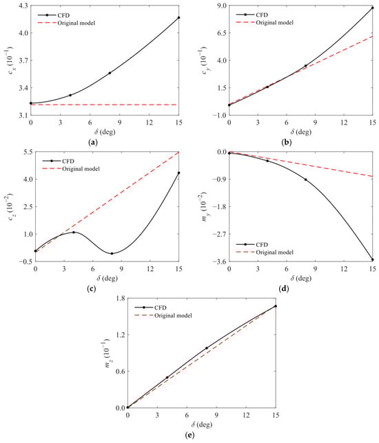
Figure 5.
Curves of aerodynamic coefficients with δ: (a) curves of cx with δ; (b) curves of cy with δ; (c) curves of cz with δ; (d) curves of my with δ; (e) curves of mz with δ.
To quantitatively assess the nonlinearity of the body aerodynamic force and moment with respect to δ, the aerodynamic coefficients are fitted as linear, 2nd-, and 3rd-order polynomials in δ. The coefficients of determination, representing the ratio of the regression sum of squares to the total departure sum of squares for cx, cy, cz, my, and mz, denoted as , , , , and , respectively, are presented in Table 3. When the fitting order is 2nd-order, , , , and have exceeded 99.00%, whereas is only 70.06% and further increases to 78.40% when the fitting order reaches 3rd. According to the closer the aerodynamic coefficient of determination is to 100%, the higher the degree of explanation of the independent variables to the dependent variable, and the better the model fits [31]; this indicates that the nonlinear characteristics of cz are more pronounced. Consequently, when establishing the body nonlinear aerodynamic model for the controlled flight of this type of aircraft, the order of cz to δ in Equations (6) and (8) should be retained at least up to the 3rd-order, while the remaining coefficients can be considered up to the 2nd-order. This further validates that the linear aerodynamic model in Refs. [4,5,6,7,8,9,10,11,25,26,27,28,30] is inadequate to accurately calculate the aerodynamic forces and moments of the aircraft body, which include higher-order nonlinear terms under large angle of attack conditions.
Table 3.
Coefficients of determination for different polynomial orders.
In addition, the influence of varying β, the angle formed between the longitudinal symmetry plane of the forebody and the complex angle of attack plane, on the body aerodynamic characteristics is analyzed. Using the specific case of υ = 0 deg as an example, simulations of the body aerodynamic force and moment are conducted at intervals of 45 deg for γF ranging from 0 deg to 360 deg, under the conditions of Ma = 1.5 and δ = 0 deg. The results reveal that cx = 0.32 remains constant and unchanged, while the variation curves of the other coefficients with γF are shown in Figure 6. It can be found that cy, cz, my, and mz are not constantly equal to 0 but exhibit periodic fluctuation, and the corresponding γF values for the extreme points may not be integer multiples of 90 deg, marking a significant departure from the previous conclusions obtained under the linear assumption.
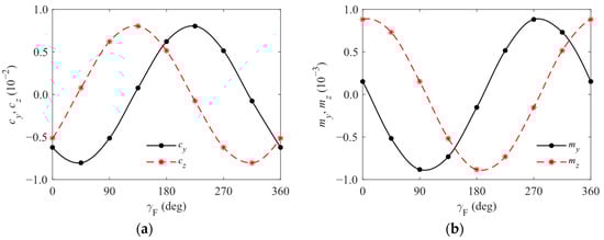
Figure 6.
Curves of aerodynamic coefficients with γF: (a) curves of cy and cz with γF; (b) curves of my and mz with γF.
For the case of δ ≠ 0 deg, by calculating the aerodynamic forces and moments acting on the aircraft body at δ values of 4 deg, 8 deg, and 15 deg, and treating each aerodynamic coefficient as fluctuating around its period mean, the coefficients of deviation representing the difference between the actual value and the period mean can be obtained for cx, cy, cz, my, and mz, denoted as , , , , and , respectively, and their variation curves with γF are shown in Figure 7. When combined with Figure 6, the observations are obtained as follows:
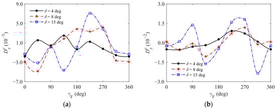
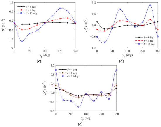
Figure 7.
Curves of coefficients of deviation with γF: (a) curves of with γF; (b) curves of with γF; (c) curves of with γF; (d) curves of with γF; (e) curves of with γF.
- As δ gradually increases, the nonlinear characteristics of aerodynamic forces and moments acting on the aircraft body become more complicated with changes in γF. This complexity manifests not only in the relatively large amplitude of fluctuations but also shifts in the positions of extreme points and even the emergence of multiple extrema within a single cycle. Consequently, to ensure the accuracy of the model, it is inappropriate to simply approximate cx, cy, cz, my, and mz as trigonometric functions of β.
- Under the specified incoming flow conditions, the fluctuation patterns of my and mz with γF vary compared to those of cz and cy, respectively. There are significant differences in trends at different δ values. Therefore, according to Equation (8), the positions of the body aerodynamic force application points for this type of aircraft also exhibit strong nonlinear characteristics that depend on both δ and β.
Furthermore, Table 4 presents the coefficients of variation, specifically , , , , and , which represent the ratio of the standard deviation to the period mean for cx, cy, cz, my, and mz, respectively. Under different δ conditions, remains around 1%, whereas and are able to approach 5%, and and even exceed 80% in some cases. According to the larger the absolute value of the coefficient of variation, the higher the degree of dispersion of the dependent variable. This indicates that and are anticipated to exert a substantial influence on cy and mz, and and are likely to dominate cz and my, respectively. Therefore, accurately describing the periodic characteristics of Fy, Fz, My, and Mz with respect to β is imperative. It further validates the assumptions outlined in Section 3.1 and also indicates that the aerodynamic models in Refs. [4,5,6,7,8,9,10,11,25,26,27,28,29,30] suffer from a large error due to the inability to theoretically describe the periodic characteristics caused by variations in the angle between the forebody longitudinal symmetry plane and the complex angle of attack plane, providing a fundamental basis for establishing an accurate model of the body nonlinear aerodynamic force and moment for this type of aircraft in this study.
Table 4.
Coefficients of variation for different δ.
4.2. Validation of Nonlinear Aerodynamic Model
4.2.1. Simplification and Parameter Solution
Based on the previous analysis and the numerical simulation results presented in Section 4.1, this section endeavors to validate the effectiveness of the established model for the body nonlinear aerodynamic force and moment. To simplify the model as much as possible while ensuring the accuracy, the 2nd-order nonlinear terms of cx and cy, along with the 3rd-order nonlinear terms of cz, are initially retained with respect to δ. Following this, the expressions of the body aerodynamic force coefficients can be derived from Equation (6) as follows:
Furthermore, by retaining the 2nd-order nonlinear terms of my and mz with respect to δ, the expressions of the body aerodynamic moment coefficients can be obtained from Equations (8) and (17) as follows:
where fi,j and hi,j can be determined by the method proposed in Section 3.2. As β equals γF when υ = 0 deg, the variation of fi,j and hi,j with β can be derived by selecting multiple sets of the body aerodynamic force and moment coefficients that correspond to different γF to fit as polynomials of δ, along with substituting them with the parameters of the original aircraft into Equations (14) and (19). Considering the relatively minor periodic variation of cx, it is reasonable to treat f1,j as constants. The remaining parameters are subsequently subjected to Fourier transformations to derive their 0th-, 1st-, and 2nd-order coefficients, as shown in Table 5 and Table 6.
Table 5.
The Fourier coefficients of fi,j.
Table 6.
The Fourier coefficients of hi,j.
Taking the Magnus force and moment, which exhibit strong nonlinearity, as an illustrative example, Figure 8 presents the calculated values at δ = 8 deg and 15 deg using the established model under the condition of Ma = 1.5 and υ = 0 deg. Notably, the solutions corresponding to the 0th- and 1st-order Fourier series have significantly larger errors compared to those of the 2nd-order Fourier series. The results indicate these points as follows:
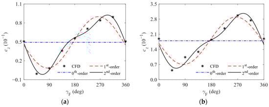
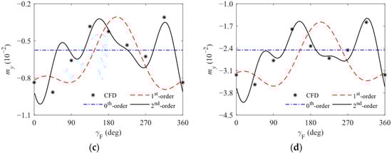
Figure 8.
Curves of cz and my with γF at different δ: (a) curves of cz at δ = 8 deg; (b) curves cz at δ = 15 deg; (c) curves of my at δ = 8 deg; (d) curves my at δ = 15 deg.
- When considering the 2nd- or 3rd-order nonlinear terms and utilizing the 2nd-order Fourier series for parameters transformation, the solutions obtained from the nonlinear aerodynamic model align closely with the CFD simulation results. Specifically, under the given Mach number, the accurate predictions of the body aerodynamic forces and moments at arbitrary complex angles of attack and forebody roll angles can be realized using the finite parameters, based on the aerodynamic parameters obtained from several experimental or simulation sets. This validates the reasonableness and feasibility of the model for the body aerodynamic force and moment established in this paper.
- Since the results corresponding to the 0th-order Fourier series are essentially obtained by using the model that retains the higher-order terms of δ based on the “Original model” but neglects the periodic characteristics of aerodynamic forces and moments, the models used in Refs. [4,5,6,7,8,9,10,11,25,26,27,28,29,30] are only applicable to cases where δ is relatively small or for calculating periodic average values under the uncontrolled flight with a freely rolling forebody. Theoretically, these models are unable to describe the fluctuating characteristics as shown in Figure 8, potentially resulting in maximum relative errors exceeding 100% for cz and my. In contrast, the model represented by Equations (21) and (22) can accurately capture the nonlinear aerodynamic forces and moments acting on the aircraft body under arbitrary δ, υ, and γF conditions. Therefore, the model established in this paper offers significant advantages for calculating the body nonlinear aerodynamic force and moment of this type of aircraft within a wider range of angles of attack.
4.2.2. Impact on Nonlinear Ballistics
To facilitate the accurate impact analysis of the body nonlinear aerodynamic force and moment on the ballistic characteristics of this type of aircraft, the aerodynamic combined parameter bz = ρScz/(2mδ) is initially introduced based on the angular motion theory detailed in Refs. [5,29]. Subsequently, the nonlinear complex angle of attack equation, incorporating the Magnus force term, can be established as follows:
where and are the 1st-order derivatives of δ1 and δ2 with respect to the arc length; and are the 2nd order derivatives of δ1 and δ2 with respect to the arc length; a11, a12, a21, a22, b11, b12, b21, and b22 are the elements of the coefficient matrix in the original equation; c1 and c2 are the coefficients of the non-homogeneous terms in the original equation; η = vNx/v, vNx is the component of the aircraft velocity vector along the OxN axis; P = Cp/(Av), C and A are the polar and equatorial moment of inertia of the aircraft, respectively.
By substituting Equations (21) and (22) into Equation (23) and assuming that the initial perturbation has converged, the ballistic simulations are conducted at the starting control point using the established mode. Figure 9 depicts the results of the complex perturbation angle of attack curves for γF values of 0 deg, 90 deg, 180 deg, and 270 deg. When considering the nonlinear terms of body aerodynamic forces and moments, and their variation characteristics with δ, υ, and γF, compared with the results obtained using the original aerodynamic model—a model that is essentially identical to those in Refs. [4,5,6,7,8,9,10,11,25,26,27,28,29,30]—the final equilibrium position of the complex perturbation angle of attack has little difference. However, notable disparities emerge in the convergence speed of the free angular motion, with the amplitude attenuation within a slow circular period being approximately 1.5 to 3 times than that of the original literature, and the specific values fluctuating with changes in the orientation of the forebody roll angle. Consequently, a pronounced asymmetric characteristic is exhibited in the three-circular angular motion during the initial controlled flight stage, resulting in a deviation of approximately 0.67 deg before the completion of the 1st cycle period, which is about 30% of the original equilibrium angle.
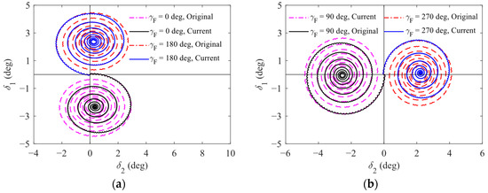
Figure 9.
Curves of complex perturbation angle of attack at different γF: (a) curves for γF = 0 deg and 180 deg; (b) curves for γF = 90 deg and 270 deg.
Furthermore, given that this type of aircraft typically employs the control strategy involving multiple adjustments to the control orientation of the forebody roll angle, it is imperative to examine the angular motion characteristics following multiple control actions applied at designated intervals. Therefore, Figure 10 further presents the curves of the complex perturbation angle of attack as γF sequentially changes with 0 deg, 90 deg, 180 deg, and 270 deg at intervals of 5 s or 10 s. Notably, the deviations between the results obtained by using the original aerodynamic model and the current aerodynamic model become more pronounced. Drawing upon the angular motion theory and the response relationship of the complex deflection angle to the complex perturbation angle of attack, as detailed in Refs. [28,29,30], it is evident that the nonlinear aerodynamic forces and moments acting on the aircraft body significantly alter the turning amplitude and phase of the average velocity deflection angle. When the switching frequency of γF is higher and leads to mutual interference among the actions of various control orientations, the significance of this effect becomes particularly prominent. Consequently, the controlled angular motion and the corrected ballistic prediction often deviate from the actual situations. This further validates the important influence on ballistic characteristics, indicating that the established model of the body nonlinear aerodynamic force and moment in this paper can provide important references for the in-depth study into the nonlinear ballistic theory of this type of aircraft.
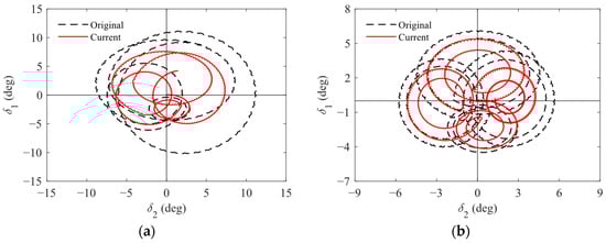
Figure 10.
Curves of complex perturbation angle of attack with multiple switching of γF: (a) curves for γF switching at 5 s intervals; (b) curves for γF switching at 10 s intervals.
5. Conclusions
This paper primarily focuses on establishing an accurate model of the body nonlinear aerodynamic force and moment for the canard dual-spin aircraft. It analyzes the body nonlinear aerodynamic characteristics exhibited by this type of aircraft during flights at large angles of attack and their subsequent impact on ballistic performances. The effectiveness of the proposed model is validated through numerical simulation methods. The key conclusions of the present investigation are summarized as follows.
By comprehensively considering the effects of various factors such as the canard–body interference and the fore/aft body reversal, the aerodynamic model completely reflects the intricate relationship between the body aerodynamic force and moment, and various flight conditions, including incoming flow characteristics. Compared with the linear aerodynamic models established in the previous literature and commonly used in ballistic numerical simulation, the proposed model is capable of accurately calculating the aerodynamic forces and moments for any given δ, υ, and γF, particularly excelling in capturing the nonlinear features at large angles of attack and the periodic characteristics caused by changes in the angle between the forebody longitudinal symmetry plane and the complex angle of attack plane.
The coupling effect of the forebody roll angle with the amplitude and phase of the complex angle of attack results in strong nonlinear characteristics in the body aerodynamic force and moment. As δ increases, it not only necessitates the retention of the higher-order terms associated with the aerodynamic forces and moments acting on the aircraft body but also exacerbates the periodic fluctuation characteristics arising from changes in the angle between the forebody longitudinal symmetric plane and the complex angle of attack plane, even leading to changes in the direction of Magnus force and moment. Consequently, it is inappropriate to simply approximate fit the coefficients of the body aerodynamic force and moment as trigonometric functions of β.
The action points of the aerodynamic forces of the aircraft body also exhibit strong nonlinear characteristics. Their combined effect with the body aerodynamic forces can significantly influence the aerodynamic moments. Consequently, the fluctuation trends of My and Mz with β change from those of Fz and Fy, and there are obvious differences in this characteristic under different δ conditions. Therefore, it is imperative to accurately describe their relationship with δ, υ, and γF in the modeling.
The nonlinear terms of the aerodynamic forces and moments acting on the aircraft body have significant influences on the complex perturbation angle of attack of this type of aircraft. These effects alter the turning amplitude and phase of the average velocity deflection angle during flight control, ultimately leading to a discrepancy between the predicted and actual corrected ballistics. Therefore, their effect on the ballistics should not be neglected in the modeling process. Through theoretical analysis and numerical simulations, it is validated that the established accurate nonlinear aerodynamic force and moment engineering model can significantly improve the angular motion and trajectory calculations compared with the previous aerodynamic model, which provides the theoretical basis and reference for the in-depth study of the nonlinear angle theory and ballistic correction strategies for this type of aircraft.
Although the body nonlinear aerodynamic characteristics observed in this paper are manifested in canard dual-spin aircraft, considering that their occurrence is due to the altered interference effect of canards on the flow around the aircraft body, it is clear that these phenomena are not unique to this type of aircraft. For example, in canard-guided aircraft, the canard–body interference effect exerts an influence on the flow around the aircraft body, and this influence differs at different deflection angles, leading to the body aerodynamic force and moment exhibiting strong nonlinear characteristics with an increase of δ as well as periodic variations under the coupled influence of pitch and yaw canards. Therefore, the conclusions obtained in this study further provide a valuable reference for research on other types of aircraft, including canard-guided aircraft.
Author Contributions
X.Z. and J.S. designed the research methodology and wrote the main manuscript. X.Z., H.R., and Z.W. carried out the numerical simulation calculation. All the authors reviewed the manuscript. All authors have read and agreed to the published version of the manuscript.
Funding
This research received no external funding.
Data Availability Statement
The data supporting the findings of this study are comprised solely of original data. Further inquiries can be directed to the corresponding author on reasonable request.
Conflicts of Interest
The authors declare no conflicts of interest.
References
- Pettersson, T.; Buretta, R.; Cook, D. Aerodynamics and Flight Stability for a Course Corrected Artillery Round. In Proceedings of the 23rd International Symposium on Ballistics, Tarragona, Spain, 16–20 April 2007; pp. 647–653. [Google Scholar]
- Xing, B.N.; Du, Z.H.; Du, C.X. Review on Two-Dimensional Trajectory Correction Projectile and Its Guidance and Control Technology. J. Natl. Univ. Def. Technol. 2021, 43, 53–68. [Google Scholar]
- Wang, Z.Y.; Shi, J.G.; Chang, S.J.; Li, Y.; Chen, Q.; Yi, W.J.; Wang, X.G. Review on Development of Technology of Trajectory Correction Projectile. J. Ballist. 2021, 33, 1–12. [Google Scholar]
- Costello, M.; Peterson, A. Linear Theory of a Dual-Spin Projectile in Atmospheric Flight. J. Guid. Control Dyn. 2000, 23, 789–797. [Google Scholar] [CrossRef]
- Zhao, X.X.; Shi, J.G.; Wang, Z.Y.; Zhang, N. Study on Angular Motion Characteristics and Control Stability with the Fixed Canard Dual-Spin Projectile. J. Harbin Inst. Technol. 2022, 54, 123–131. [Google Scholar]
- Theodoulis, S.; Gassmann, V.; Wernert, P.; Dritsas, L.; Kitsios, I.; Tzes, A. Guidance and Control Design for a Class of Spin-Stabilized Fin-Controlled Projectiles. J. Guid. Control Dyn. 2013, 36, 517–531. [Google Scholar] [CrossRef]
- James, M.M. Efficient Attitude Estimation for a Spin-Stabilized Projectile. J. Guid. Control Dyn. 2016, 39, 339–350. [Google Scholar]
- Ma, G.L.; Cai, H.M.; Chang, S.J. Analysis of Dynamic Stability of Fixed Canard Dual-Spin Projectile. Acta Armamentarii 2019, 40, 1987–1994. [Google Scholar]
- Norris, J.; Hameed, A.; Economou, J.; Parker, S. A Review of Dual-Spin Projectile Stability. Def. Technol. 2020, 16, 1–9. [Google Scholar] [CrossRef]
- Zhang, D.J.; Zhang, J.; Jiao, Z.G.; Ni, Q.J.; Guo, Q.P. Correction-Efficiency-Coefficient-Based Trajectory Optimization for Two-Dimensional Trajectory Correction Projectile. Aerospace 2022, 9, 149. [Google Scholar] [CrossRef]
- Krishna, A.B.; Kothari, M.; Abhishek, A. Guidance and Control of Spin-Stabilized Projectiles Based on Super Twisting Algorithm. J. Guid. Control Dyn. 2023, 46, 417–617. [Google Scholar] [CrossRef]
- Regan, F.J.; Smith, J. Aeroballistics of a Terminally Corrected Spinning Projectile (TCSP). J. Spacecr. Rocket. 1975, 12, 733–738. [Google Scholar]
- Xu, H.W.; Chen, S.S. Comparison of Aerodynamic Characteristics of Two-Dimension Trajectory Correction Projectile with Reverse-rotation and Non-rotation PGK. J. Ballist. 2018, 30, 32–37. [Google Scholar]
- Liu, X.D.; Wu, X.S.; Yin, J.T. Aerodynamic Characteristics of a Dual-Spin Projectile with Canards. Proc. Inst. Mech. Eng. Part G J. Aerosp. Eng. 2019, 233, 4541–4553. [Google Scholar] [CrossRef]
- Feng, B.; Yu, J.Y.; Ju, T.; Wang, X.M.; Wang, Y. Numerical Study of Asymmetrical Load on the Body of Dual-Spin Projectile. Acta Armamentarii. 2018, 39, 2118–2126. [Google Scholar]
- Feng, B.; Yu, J.Y.; Wang, X.M.; Wang, Y. Numerical Study on the Flow Around Dual-Spin Rocket Projectile Body. J. Ballist. 2021, 33, 21–27. [Google Scholar]
- Silton, S.I.; Fresconi, F. Effect of Canard Interactions on Aerodynamic Performance of a Fin-Stabilized Projectile. J. Spacecr. Rocket. 2015, 52, 1430–1442. [Google Scholar] [CrossRef]
- Zhang, J.W.; Lei, J.M.; Niu, J.P. Numerical Investigation of Aerodynamic Characteristics of Free-Spinning Tail Projectile with Canards Roll Control. Proc. Inst. Mech. Eng. Part G J. Aerosp. Eng. 2021, 235, 687–702. [Google Scholar] [CrossRef]
- Qian, L.; Chang, S.J.; Yang, W.L.; Wei, W. Simulation on Nonlinear and Unsteady Aerodynamic Characteristics of Fixed-Canard Correction Projectile. J. Ballist. 2020, 32, 31–37. [Google Scholar]
- Ji, X.L.; Wang, H.P.; Zeng, S.M.; Li, D.G. CFD Prediction of Longitudinal Aerodynamics for a Spinning Projectile with Fixed Canard. Trans. Beijing Inst. Technol. 2011, 31, 265–268. [Google Scholar]
- Zhang, D.J.; Zhang, J.; Jiao, Z.G.; Ni, Q.J. Research on Aerodynamic Characteristics of Correction Mechanism of Two-Dimensional Trajectory Correction Projectile. J. Ballist. 2021, 33, 34–39. [Google Scholar]
- Cheng, J.; Yu, J.Y.; Wang, X.M.; Yao, W.J. Engineering Modeling and Identification of Aerodynamics of Trajectory Correction Projectile with Decoupled Canards. Acta Armamentarii 2014, 35, 1542–1548. [Google Scholar]
- Feng, B.; Yu, J.Y.; Wang, Y.; Wang, X.M.; Ju, T. Improvement and Parameter Identification of Correction Force Model for Fixed-Canard Guidance Kit. Acta Armamentarii 2019, 40, 257–264. [Google Scholar]
- Zhong, Y.; Wang, L.M.; Li, Y.; Yang, Z.W. Calculation Model of Normal Force of Canard on Spin Stabilized Two-Dimensional Trajectory Correction Projectile. J. Ballist. 2019, 31, 48–54. [Google Scholar]
- Chang, S.J. Dynamic Response to Canard Control and Gravity for a Dual-Spin Projectile. J. Spacecr. Rocket. 2016, 53, 558–566. [Google Scholar] [CrossRef]
- Steven, T.; Spilios, T.; Sovanna, T.; Michael, P. Nonlinear Dynamic Inversion Flight Control Design for Guided Projectiles. J. Guid. Control Dyn. 2020, 43, 975–980. [Google Scholar]
- Fresconi, F.; Rogers, J. Flight Control of a Small-Diameter Spin Stabilized Projectile Using Imager Feedback. J. Guid. Control Dyn. 2015, 38, 181–191. [Google Scholar] [CrossRef]
- Zhao, X.X.; Shi, J.G.; Wang, Z.Y.; Zhang, N. Dynamic Stability and Influence Factors of the Whole Trajectory of Fixed Canard Dual-Spin Projectiles. Chin. J. Theor. Appl. Mech. 2022, 54, 1366–1376. [Google Scholar]
- Zhao, X.X.; Shi, J.G.; Wang, Z.Y.; Zhang, N. Nonlinear Angular Motion and Bifurcation Characteristics of Canard Dual-Spin Projectiles. Acta Armamentarii 2023, 44, 3067–3078. [Google Scholar]
- Li, H.Y.; Shen, Q.; Deng, Z.L. Analysis of Angular Motion and Swerving Response Characteristics of Dual-Spinning Two-Dimensional Correction Projectile With Canard Layout. Acta Armamentarii 2024, 45, 1866–1876. [Google Scholar]
- Chicco, D.; Warrens, M.J.; Jurman, G. The Coefficient of Determination R-Squared is more Informative than SMAPE, MAE, MAPE, MSE and RMSE in Regression Analysis Evaluation. PeerJ Comput. Sci. 2021, 7, e623. [Google Scholar] [CrossRef]
Disclaimer/Publisher’s Note: The statements, opinions and data contained in all publications are solely those of the individual author(s) and contributor(s) and not of MDPI and/or the editor(s). MDPI and/or the editor(s) disclaim responsibility for any injury to people or property resulting from any ideas, methods, instructions or products referred to in the content. |
© 2025 by the authors. Licensee MDPI, Basel, Switzerland. This article is an open access article distributed under the terms and conditions of the Creative Commons Attribution (CC BY) license (https://creativecommons.org/licenses/by/4.0/).