Article

On-Orbit Functional Verification of Combustion Science Experimental System in China Space Station

1
Institute of Engineering Thermophysics, Chinese Academy of Sciences, Beijing 100190, China
2
National Key Laboratory of Science and Technology on Advanced Light-Duty Gas-Turbine, Chinese Academy of Sciences, Beijing 100190, China
*
Author to whom correspondence should be addressed.
Aerospace 2025, 12(5), 448; https://doi.org/10.3390/aerospace12050448
Submission received: 15 April 2025 / Revised: 16 May 2025 / Accepted: 19 May 2025 / Published: 20 May 2025
(This article belongs to the Section Astronautics & Space Science)

Abstract

:
We demonstrated the development, implementation, and functional verification of the combustion science payload deployed on the China Space Station. The Combustion Science Experiment System (CSES) integrated seven subsystems and modular plugins to address the major challenges facing microgravity combustion research, including the lack of long-duration experimental platforms, spatial constraints, and safety risks. Through on-orbit testing, the core functions of the CSES under microgravity conditions were validated, including gas supply, ignition, combustion diagnostic, exhaust purification, and emission. The system achieved autonomous experiment execution by ground-injected commands. Data from on-orbit methane combustion experiments demonstrated that the CSES was capable of stably supplying oxygen and fuel gas at a preset flow rate, real-time combustion diagnosis, and provided high-resolution flame image. Effectively exhaust gas purification and emission control of the CSES have also been tested and verified. It provides a safe, reliable, and stable microgravity environment of long-duration research for the combustion science and the development of spacecraft fire safety technology.

1. Introduction

Combustion is a primary means for humans to obtain energy, power, and generate thrust [1,2,3,4]. Under normal gravity conditions, buoyancy-driven convection and gravitational settling complicate combustion phenomena, making in-depth understanding of combustion challenging [5,6,7]. Microgravity conditions provide new opportunities to understand the mechanisms of combustion [8,9], while the safe and efficient operation of crewed spacecraft [10,11,12] also pose new challenges for combustion research. Deepening our understanding of ground-based combustion [13,14] and enhancing insights into fire safety issues in crewed spacecraft [15,16] have consistently been two objectives driving microgravity combustion studies. There are two approaches to create a microgravity environment: one involves moving away from Earth’s surface, while the other uses free-fall principles on the ground. Consequently, facilities for obtaining microgravity conditions can be categorized into ground-based (e.g., drop tower [17], drop shaft [18], drop vehicle [19], parabolic aircraft [20], high-altitude balloon platform [21], and sounding rocket [22]) and space-based (e.g., space station [23], space shuttle [24], spacecraft [25], and artificial satellite [26]) facilities.
Microgravity experiments conducted on ground-based platforms have yielded significant research findings with the limited duration of microgravity (<10 s) [27]. While satellite orbital experiments allow for long-term observation of flame dynamics, they are constrained in experimental scalability due to fixed experimental conditions, limited measurement methods, and an inability to systematically conduct microgravity combustion studies [28]. Given that microgravity combustion experiments involve diverse sample types, long characteristic times, and high requirements for measurement and diagnostic techniques, conventional ground-based facilities often fail to provide sufficient experiment duration or space under simulated microgravity conditions to meet research needs [29]. In contrast, space stations can offer ample time for microgravity experiments and achieve higher levels of microgravity. They enable systematic microgravity combustion studies with the ability to replace samples, involve human participation, and employ advanced measurement and diagnostic techniques. Therefore, the current trend in microgravity combustion experiments is to utilize space stations as the primary platform for such research, while other microgravity experiment facilities serve as effective supplementary tools. Simultaneously, ground-based microgravity facilities are used to optimize experimental conditions for space station-based combustion studies.
In terms of space experiments, the United States, Europe, Japan, and other regions have conducted extensive studies on space combustion using the International Space Station (ISS) [30]. These studies were carried out through combustion experiment modules installed aboard the space station, with results holding significant importance for microgravity combustion research [31]. From the existing findings in microgravity combustion studies, advanced, reliable, and specifically tailored experimental technologies are essential for successfully completing space-based combustion experiments [28]. Currently, advancements in space combustion experimental techniques and equipment focus on achieving multifunctional and modular designs, reusable capabilities, and the incorporation of cutting-edge diagnostic technologies with efforts aimed at generating a rich and comprehensive dataset [32]. Although China’s microgravity combustion research began in the 1990s, with the 3.6 s drop tower facility at the Chinese Academy of Sciences’ Microgravity Laboratory enabling of short-duration microgravity experiments [33,34,35,36,37], China’s research in the space combustion field has been constrained by limited experimental opportunities and dependence on shared resources with other missions. With the establishment of the China Space Station (CSS), this situation has been improved [38,39,40,41,42,43,44,45,46,47]. The Combustion Science Experiment System (CSES) deployed in the CSS will provide an opportunity for in-depth exploration of microgravity combustion research. For this purpose, the design [48], manufacturing, and implementation of the CSES must consider the safety, universality, and efficient use of resources for multi-fuel testing, coupled with advanced diagnostic techniques [49,50,51] for fulfilling the experimental requirements.
In this paper, we demonstrate the composition of the CSES aboard the CSS, propose an adjustable on-orbit experimental procedure by command-injection, and realize a microgravity combustion for a closed, variable-oxygen environment. The functionality and performance of the CSES are studied for supporting long-duration combustion experiments under actual orbital conditions, including gas propellant supply, ignition control, combustion diagnostics, and exhaust gas treatment.

2. Combustion Science Experimental System

2.1. Composition of the CSES

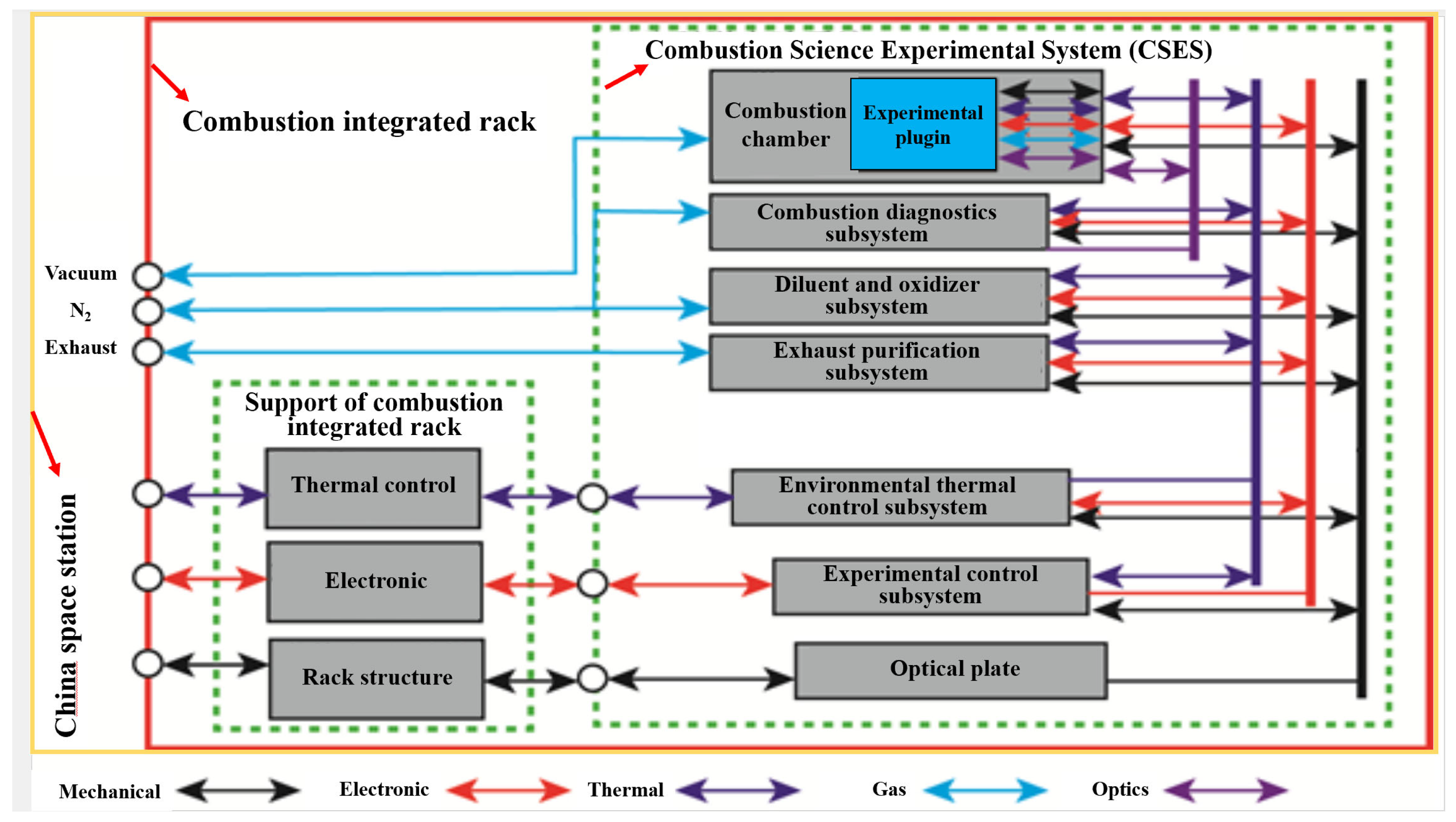
The CSES represents a multi-functional and scalable scientific platform, comprising an integrated set of subsystems, each designed to perform specific experimental functions. Figure 1 demonstrates the general layout of the CSES, consisting of seven subsystems and modular plugin. The physical structure model of the CSES and distribution positions of the main subsystems are illustrated in Figure 2. On-orbit combustion experiment is carried out in the closed chamber by installing the experimental plugin and connecting the mechanical, electrical, thermal, gas and optical interfaces. The interfaces of the seven subsystems and a plugin in the CSES are shown in Figure 3.
  • The optical plate serves as the structural backbone of the system. Integrated mechanically with the rack, it supports the installation of key components.
  • The combustion chamber provides a sealed and isolated environment for combustion experiments. As a central hub, it connects experimental plugins to the platform. Additionally, eight optical windows located at the center of the chamber enable observations.
  • The diluent and oxidizer subsystem is responsible for storing and managing high-pressure oxygen and inert gasses, as well as integrating nitrogen resources from the CSS. Based on the required atmosphere configuration, it delivers gas reactants into the chamber at specified flow rates with precision.
  • Modular experimental plugins are installed within the chamber to provide ignition, fuel supply, and signal acquisition functions for combustion experiments.
  • The combustion diagnostics subsystem employs non-contact measurement techniques to capture critical experimental data. It comprises eight optical devices, which are in one-to-one correspondence with the eight observation windows arranged circumferentially around the combustion chamber. Additionally, this subsystem supports the integration of additional diagnostic equipment through standardized interfaces.
  • The exhaust purification subsystem collects various combustion byproducts. These byproducts undergo compositional analysis and real-time recycling cleaning to ensure safe release.
  • The experimental control subsystem manages power distribution and data communication. Power at 100 V and 28 V is received and distributed to scientific instruments via a power conversion unit equipped with gigabit Ethernet and RS422 interfaces.
  • During the operation, an environmental thermal control subsystem ensures safe equipment operation through a combined air-cooling and water-cooling approach.

2.2. Operation Principle of the CSES

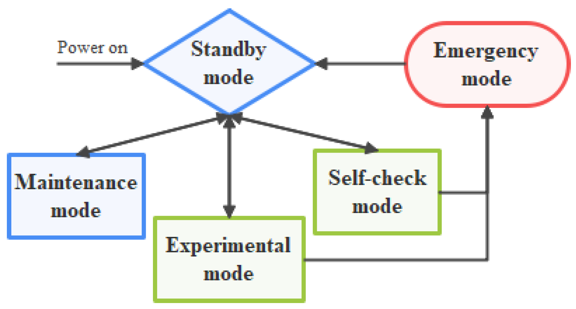
During the on-orbit operation, the CSES has five working modes: standby mode, self-check mode, experimental mode, emergency mode, and maintenance mode. The modes switching is illustrated in Figure 4. After startup or completing other modes, the system automatically defaults to standby mode. In standby state, the system collects environmental parameters, including combustion chamber temperature and pressure, exhaust pressure, cylinder pressure, and external combustion chamber temperature. When receiving a self-check command, the system enters self-check mode and performs checks on exhaust, intake, diagnostic subsystems, environmental control subsystems, and experimental plugin functionality. It also verifies communication statuses of system modules, including the combustion controller, plugin, power supply, and network storage units. Based on uploaded commands generated from combustion experiment plans, the system executes a series of preset events to acquire engineering data, scientific data, and combustion images. Importantly, engineering data are transmitted to the ground in real-time for analysis during experiments. After completing experiments, scientific data are downloaded for further detailed analysis. If faults are detected during self-testing or experiments, the system enters emergency mode. Fault levels are determined according to fault plans and addressed promptly. Correspondingly, ground personnel remotely intervene and troubleshoot based on status feedback, and fault location through telemetry of engineering data. Additionally, upon receiving a command to enter maintenance mode, software upgrades, maintenance, and repairs can be performed onboard during operations.

2.3. Procedure of Combustion Experiment in the CSES

The CSES utilizes the on-orbit spatial environmental conditions provided by the space station to support a variety of microgravity combustion research through the replacement of different plugins. Three plugins are categorized, including gaseous, liquid, and solid combustion modules. Each type is designed for specific fuel types and can be reused multiple times. The gas plugin along with the CSES were the first to be launched into the CSS, while the liquid and solid combustion plug-ins will be launched and replaced as needed based on subsequent experimental requirements. On-orbit period of gas plugin, six types of microgravity combustion scientific experiments are planned: (1) The mechanisms of steady, lifted, and blow-off of laminar partially premixed flames. (2) The formation characteristics of soot in laminar diffusion flames under microgravity. (3) Small-scale turbulence combustion under microgravity conditions. (4) The soot formation mechanisms of C1-C4 hydrocarbon fuels under microgravity. (5) The dynamic evolution laws of micro and nano particles under microgravity. (6) The flame synthesis mechanisms of semiconductor nanomaterials under microgravity. Based on the collection and statistics of gaseous fuel requirements, the primary gaseous fuels include hydrogen (H2), methane (CH4), and ethylene (C2H4). Additionally, other fuels can also be supported by replacing fuel cylinders, such as propene (C3H6), carbon monoxide (CO), and mixed gasses containing dimethyl ether (DME). Currently, microgravity combustion experiments focusing on CH4 as the research subject are being intensively conducted on orbit.
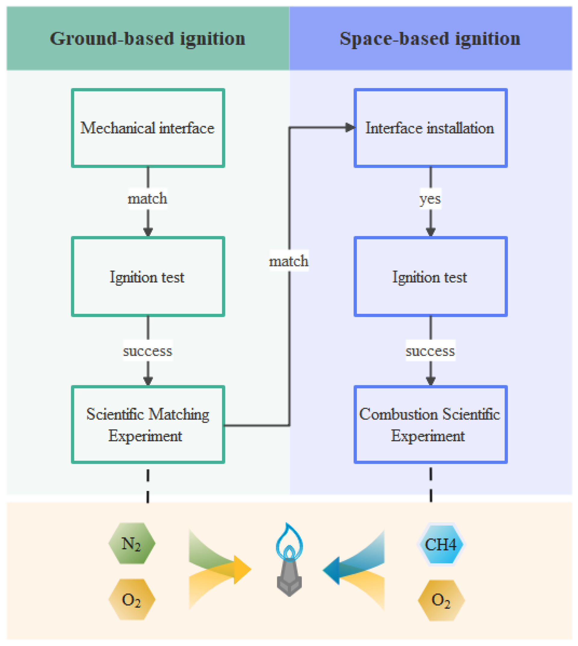
There are two sets of CSESs: one operational on orbit and the other located on the ground. All the on-orbit combustion projects that have undergone rigorous peer reviews are permitted to conduct combustion experiments in the CSES. The ignition test carried out initially serves as a crucial and essential step in guaranteeing the safe execution of the on-orbit combustion experiment as shown in Figure 5. The interface matching tests primarily focus on mechanical compatibility. The experimental modules of the combustion project undergo self-inspection to ensure compatibility with the corresponding interfaces of the gas experiment plugin. Successful installation of the modules during the test assembly confirms interface compatibility, which is critical for ensuring seamless integration of the experimental apparatus. Following successful interface matching, preliminary ignition tests are conducted on the ground-based ignition device using the ignition parameters provided by the combustion project to evaluate the thresholds for successful ignition. Successful ignition tests indicate that the combustion project has capable of conducting scientific matching experiments in the ground-based CSES. Subsequently, the ground-based CSES is activated, including the thermal control system, combustion science experiment platform, gas experiment plugin, and other foundational support equipment, and initialized to ensure operational readiness. According to the combustion environment, ignition, and diagnostic parameter settings, the experimental parameters are set up to conduct combustion experiments. After completing the experiment, scientific data are downloaded and transmitted, and exhaust gasses and scientific experimental data are analyzed. Through these tests, a comprehensive evaluation of the ignition parameters is conducted to determine their reliability in achieving ignition, which serves as the foundation for the on-orbit combustion science experiments.
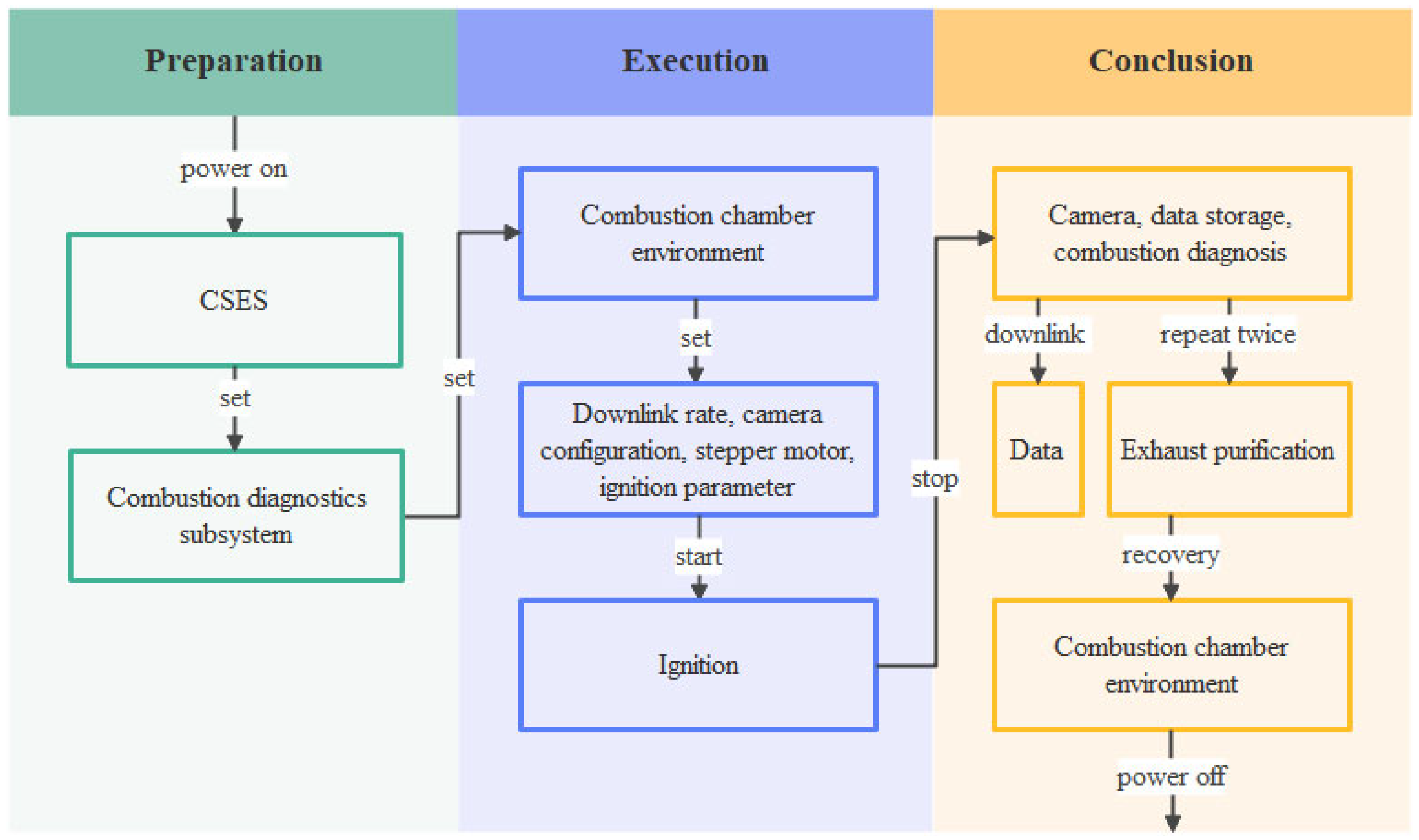
Under the typical working conditions of microgravity, pressure and temperature provided by the CSES in the CSS, the gas combustion of follows an extremely rigorous and interlinked operation process as shown in Figure 6. First, experimental preparation is conducted, which includes powering on the CSES. Subsequently, nitrogen gas inflow self-inspection tests are performed to ensure normal nitrogen gas supply, and the combustion chamber environmental parameters and downlink rates are configured in turn. Then, pre-experiment preparations are completed, such as camera configuration and fuel line air purging, followed by enabling step motor application data and operating parameters. Particularly, ignition parameters are configured. After the experiment concludes, the wide-angle camera power is turned off sequentially, camera data collection is terminated and experimental data are stored, combustion diagnostic equipment power is disconnected, application data are downlinked. Following diaphragm pump circulation filtration is initiated, electrochemical equipment power is disconnected, and two negative pressure relief operations to 0.01 atm (1 kPa) are conducted. The combustion chamber is then restored to 1 atm (100 kPa). Finally, the system is powered off, completing the entire experimental process.

3. Technical Indicator of the CSES

The design of the CSES strictly adhered to the relevant standards and requirements to ensure its functionality, performance, and reliability meet various combustion experimental needs. Table 1 presents the basic design requirements of the system and the corresponding indicators for their implementation and realization. It was equipped with high-reliability materials and mature manufacturing processes to ensure product quality meets design requirements. All key components undergone rigorous quality inspections and performance tests, conforming to relevant quality standards. The system design emphasized long-term stability and durability to satisfy the demanding environment of on-orbit experiments.

3.1. Physical Structure

The system’s external dimensions have been designed to comply with the spatial constraints of the experimental module. Specifically, the dimension of the CSES was 944 mm × 752 mm × 1100 mm, ensuring reasonable installation and operation space within the experimental module. The design focused on compactness and efficient space utilization while facilitating operator access and maintenance. The installation requirements for the CSES were clearly defined, which must be fixed at designated positions within the experimental module to prevent displacement caused by vibrations or shocks during operation. Standard threaded connections were used for installation interfaces to enable quick installation and disassembly. Additionally, reliable connections were established with the experimental module’s power supply, gas supply, and information interfaces to ensure smooth progress of experiments.

3.2. Information Interface

The system employed standardized design for its information interfaces, ensuring seamless integration with the experimental module’s data management and transmission systems. Various sequenced commands were supported by programmable command interface for rapid response and execution, including experiment initiation, termination, and parameter adjustment. Experimental parameters and control commands can be transmitted to the system through data injection interface, with transmission rate and format optimized to minimize latency and error rates. Engineering parameters such as combustion chamber pressure, temperature, and gas flow rate are collected in real-time and transmitted through telemetry interface to ensure the accuracy and integrity of the transmitted data. Additionally, experimental data are stored, processed, and transmitted through the data management and transmission interfaces. As a result, reliable, real-time data transfer can be achieved, providing support for the operation of the experiment and system.

3.3. Power Supply

The system’s total power consumption had been optimized to ensure it operated within the power supply range of the experimental module. Under typical operation, the peak power consumption was 170 W, complying with the experimental module’s power distribution requirements. Inevitably, the system generated heat during operation, making thermal control design critical. Two independent cooling water circuits using ethylene glycol-based aqueous solutions are adopted to maintain the surface temperature of the modules below 45 °C. Temperature monitoring modules accurately measure the temperature changes within the system. Temperature control modules employ heat dissipation solutions, including radiators, fans, and heat pipes. Once the temperature approaches the set threshold, they promptly activate the corresponding heat dissipation devices to prevent overheating. By continuously adjusting the heat dissipation in real time, to ensure the normal performance and service life of the modules, thus safeguarding the stable operation of the system.

3.4. Combustion Diagnostics

Through the integration of eight optical devices illustrated in Figure 2, four combustion measurement units have been constructed: a high frame rate/high resolution (HFR/HR) color imaging unit (devices 1, 4, 6), a continuous collimated light imaging unit (devices 2, 6), an OH/CH weak-light detection imaging unit (devices 3, 8) and a continuous laser particle image velocimetry (PIV) unit (devices 5, 7). Table 2 lists the key technical indicators of the optical devices. Optical devices 1, 4, and 6 (HFR/HR camera) are used for measuring flame temperature fields, flame morphology, and soot concentration through multi-viewpoints. Comprising the optical device 2 (collimated light) and device 6 (HFR/HR camera), this unit can measure flame structure using the schlieren method and support other measurement techniques. Device 6 has two operational states: one for the continuous collimated light measurement unit (equipped with a knife-edge mechanism for schlieren) and another for the HFR/HR color imaging unit (without the knife-edge mechanism). The switch between states is achieved by replacing the device configuration. Devices 3 and 8 (intensified charge coupled device camera, ICCD) equipped with narrowband filters are used for detecting intermediate specific chemical species such as OH/CH during combustion. The unit’s functionality for analyzing combustion intermediate species can be expanded by replacing optical devices during on-orbit operations. Device 5 (semiconductor continuous laser) and device 7 (HFR/HR camera) are united to form a PIV unit, measuring the two-dimensional velocity field within the combustion chamber window (50 mm × 50 mm). In this way, it will provide a comprehensive non-contact diagnostic measurement capability.

3.5. Safety and Reliability

During the design and testing of the CSES, the system has strictly met its performance indicators in terms of lifespan, safety, reliability, maintainability, testability, and environmental adaptability. With the support of maintenance, the operational lifespan of the CSES in the CSS shall not be less than 10 years. Rigorous and multiple strategies such as overpressure protection, overcurrent protection, and temperature protection were adopted to ensure the safety of personnel and equipment. The system’s reliability was designed to 0.915, validated through strict design verification and reliability testing to ensure stable performance in complex environments. It adopted a modular design of maintenance interfaces and tools with quick disassembly and replacement of faulty components, which reduced maintenance time and costs. Furthermore, the system has undergone mechanical and thermal environmental tests to verify its stability and reliability under complex conditions with capable of adapting to the diverse requirements of on-orbit experiments. Mechanical tests simulated vibrations, shocks, and other loads that may be encountered during on-orbit operation, ensuring normal system performance under extreme conditions. Thermal environment tests validated the system’s performance under high and low temperatures, ensuring stability and reliability across different temperature ranges.

3.6. Ergonomics

In the aerospace field, ergonomics focuses on the rationality of crew operations and health protection in manned spacecraft. Due to the microgravity environment in the CSS, crew operations related to the CSES such as installation, maintenance, and repair are limited. Therefore, the ergonomic aspects of the CSES require careful consideration to adapt to real-space operational scenarios. The on-orbit operations of the CSES primarily include the following types: (1) removal of structural reinforcement facilities and unlocking of cargo packages; (2) general operations such as unlocking and opening the combustion chamber door; (3) replacement of the ORU. The involved operational space, operational force, operational error prevention, and operational feedback all meet the ergonomic requirements of the space system in the CSS. The operational procedures have been streamlined, and an operation guide has been developed, with crews trained according to the guide. In addition, interface safety features and intuitive markings have passed the ergonomic evaluation, such as anti-floating measures for screw disassembly, exposed thread protections, rounded edges on pipeline corners, non-slip handle designs, quick-disconnect alignment guides, and error-prevention indicators. Color coding and graphical symbols are employed to assist crews in rapidly identifying and operating equipment, reducing the risk of misoperation, and improving mission execution efficiency.
Given the system’s ability to coordinate crew participation in operations on-orbit, it has emphasis on noise control and contact temperature indicators in terms of medical health. The primary noise sources of the system were the membrane pump in the exhaust purification subsystem and the axial flow fan in the environmental thermal control subsystem. By implementing comprehensive measures such as selecting low-noise equipment and components, optimizing equipment layout, and improving pipeline design, the system successfully maintained noise levels below 60 dB during 30 min of maximum operational conditions. Additionally, the temperature at the contact point of the accessible part of the bare skin should not be higher than 45 °C and not lower than 10 °C to prevent burns or frostbite to personnel during experiments. In special cases, the minimum temperature should not be lower than 4 °C. The surface temperature of key components is strictly maintained within a safe range not exceeding 24 °C, and the system is equipped with temperature monitoring and alarm functions to ensure the safety and comfort of crew.

3.7. Capabilities Comparison

Combustion installations in ISS have been functioned in the space. The main technical parameters comparison between the CSES in the CSS and similar facilities in ISS is presented in Table 3. The CSES is comparable to those of ISS in terms of combustion experiment conditions and optical diagnosis of plugins. Moreover, the CSES has made innovations and improvements in certain aspects of camera property, light source configuration, and integration of other functions. These advancements not only narrow the technological gap with ISS in space combustion science experiment but also enhance suitability for cutting-edge microgravity combustion research.
To address challenges such as sustainability, space risks, and safety, the CSES was considered the unique requirement of combustion experiments into its design phase, with redundant designs applied to both hardware and software systems. Key pressure-bearing components—including the combustion chamber, gas cylinders, and pipelines—were engineered to withstand three times the working pressure, while maintaining a helium mass spectrometer leak rate of ≤10−6 Pa·m3/s at 1.5 times the operational pressure. Multiple sensor modules were arranged in the combustion chamber to monitor environmental parameters (e.g., pressure, oxygen concentration, fuel concentration, and temperature) at different positions. The software system preset threshold values for these parameters, enabling full-cycle and real-time monitoring of parameter changes during on-orbit experiments. Upon exceeding the thresholds, the CSES automatically initiated an emergency mode. Through measures such as emergency exhaust of waste gas and emergency power-off, the equipment would be in a safe state.
Furthermore, core equipment (e.g., mass flow meters and combustion diagnostics) were designed with modular replaceable components. If on-orbit performance degradation rendered the equipment unable to meet scientific requirements, it could be replaced via cargo spacecraft, ensuring that the CSES remains in a working condition. Through modular functional adjustments (such as adding new experimental modules), the CSES dynamically adapts to the evolving requirements of long-duration mission requirements. With redundancy, maintainability, and environmental adaptability, the modular system of the CSES provides an efficient technological solution for its long-term stable on-orbit operation, mission expansion, and safety protection, potentially delivering a service life exceeding 10 years.

4. Primary Functions Verification of the CSES

The CSES is required to establish experimental combustion conditions and enable the on-orbit installation and operation of various combustion experiments. It should be capable of supporting the entire process of on-orbit combustion experiments, including on-orbit operations, ground–space collaboration, and acquisition of experimental results. For the gas combustion experiment, the system’s ability to supply oxidizers and other gasses was tested using methane (CH4) as the primary fuel, as well as its capability to provide a closed and isolated experimental environment. The system’s capacity to filter and analyze combustion-generated exhaust gasses and its ability to perform exhaust emission through exhaust and vacuum ports were also evaluated. Furthermore, the system’s functionality to automatically conduct experiments through electronics and to monitor the status of the system was assessed.

4.1. Gas Supply and Configuration

At the initial stage of the environmental atmosphere configuration of the combustion chamber in the CSES, a critical preliminary test focused on the validation of oxidizer (O2) and nitrogen (N2) inflow functionality. To precisely control the gas inflow quantities, the system utilized advanced mass flow controllers. These controllers were equipped with high-precision flow monitoring and regulation capabilities, and their feedback parameters accurately reflected the real-time changes in O2 and N2 inflow quantities presented in Figure 7a. It demonstrated that the flow rate curves of O2 and N2 exhibit extremely smooth over time under the set flow conditions. This clearly indicates that through effective regulation by the mass flow controllers, the system is capable of stably and efficiently controlling the flows of O2 and N2, continuously supplying the required gasses for precise configuration of subsequent experimental environments. This ensures the accuracy and stability of the construction of the experimental environmental atmospheres.
As the experiment progresses to the on-orbit ignition, fuel selection and supply became critical factors. CH4 was chosen as the fuel, with O2 participating in the combustion process to simulate specific combustion conditions. Throughout the experimental process, the system implemented strict and precise monitoring and control of O2 and CH4 flow rates for suppling. The real-time flow rate is presented in Figure 7b. It showed that the flow rate of CH4 was dynamically adjusted in strict accordance with the pre-established experimental requirements. Whether the in phases of flow rate increase, stabilize, or decrease, the system demonstrated extremely high response precision and stability. It conclusively proved that the system had successfully incorporated CH4 as fuel into the combustion system and was capable of efficiently and precisely regulating CH4 and O2 flow rates based on experimental requirements. This lays a solid foundation for in-depth exploration of combustion characteristics and related scientific issues.

4.2. Fuel Gas Ignition and Combustion

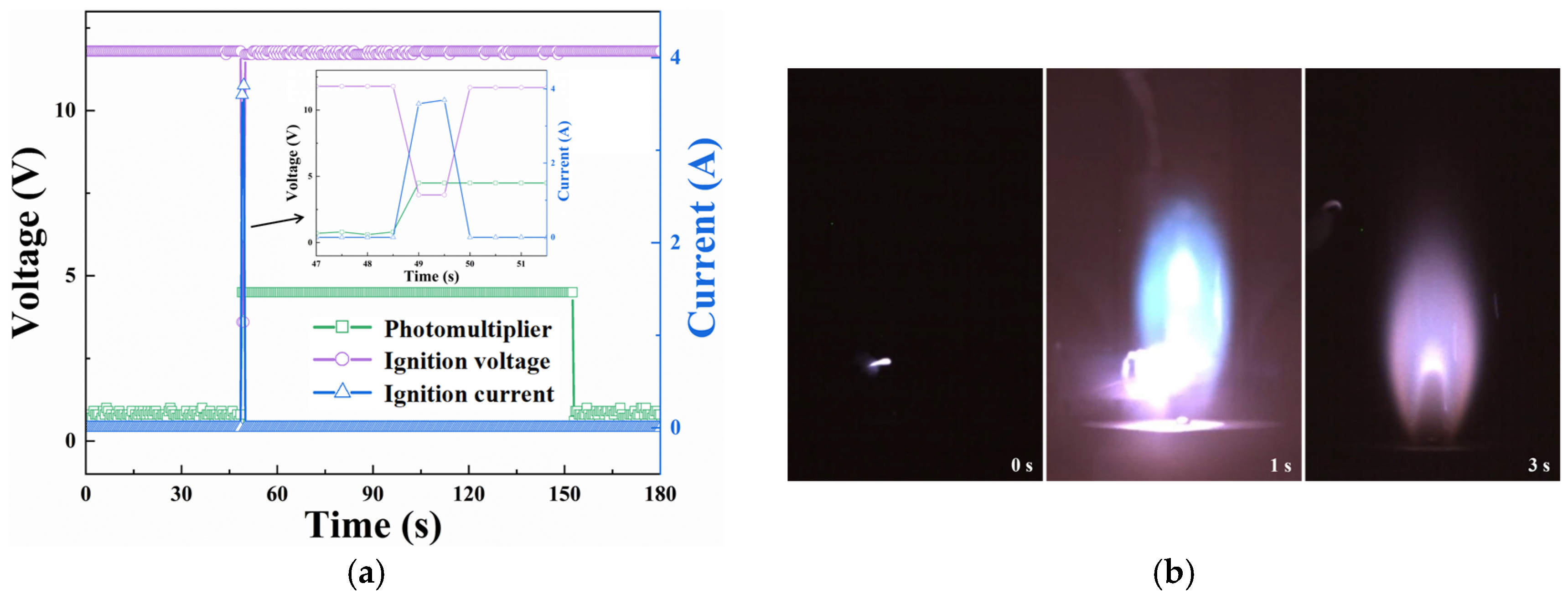
After carefully configuring the required environmental atmosphere, the electric heating wire was precisely moved to the ignition position. This process was precisely controlled by a stepper motor to ensure the electric heating wire accurately reached the predetermined ignition position. Subsequently, the electric heating wire was energized for 1 s, utilizing the heat generated by the wire to successfully ignite the gas of CH4 in the combustion chamber. During the energization of the electric heating wire, its terminal voltage and current conditions were clearly displayed in the real-time monitoring system as shown in Figure 8a. The photomultiplier tube detected the light signals generated during the combustion process and outputs corresponding voltage signals to confirm successful ignition. It is reasonable to conclude that the CH4 gas in the combustion chamber has been successfully ignited from the output voltage signal of the photomultiplier tube.
Moreover, the combustion of CH4 in the chamber was observed in real time via a wide-angle camera in the plugin. In a 70 L chamber under normal temperature (25 °C) and pressure (101.3 kPa), a nitrogen–oxygen mixture (21% O2) was established, with CH4 at a flow rate of 0.16 L/min and O2 at 0.15 L/min introduced simultaneously, mixed, and ejected through a 0.1 mm orifice. Calculations show that the premixed gas has a velocity of 6.6 m/s and a Reynolds number (Re) of 406, indicating a laminar combustion. The ignition and combustion phenomena recorded by the wide-angle camera are shown in Figure 8b. The flame’s morphology, brightness, and combustion stability were recorded in real-time, providing crucial data for in-depth combustion characteristic analysis [52]. The real-time monitoring of the photoelectric signal and the camera picture ensured the stability and reliability of the ignition interpretation process.

4.3. Filtering and Analysis of Exhaust Gasses

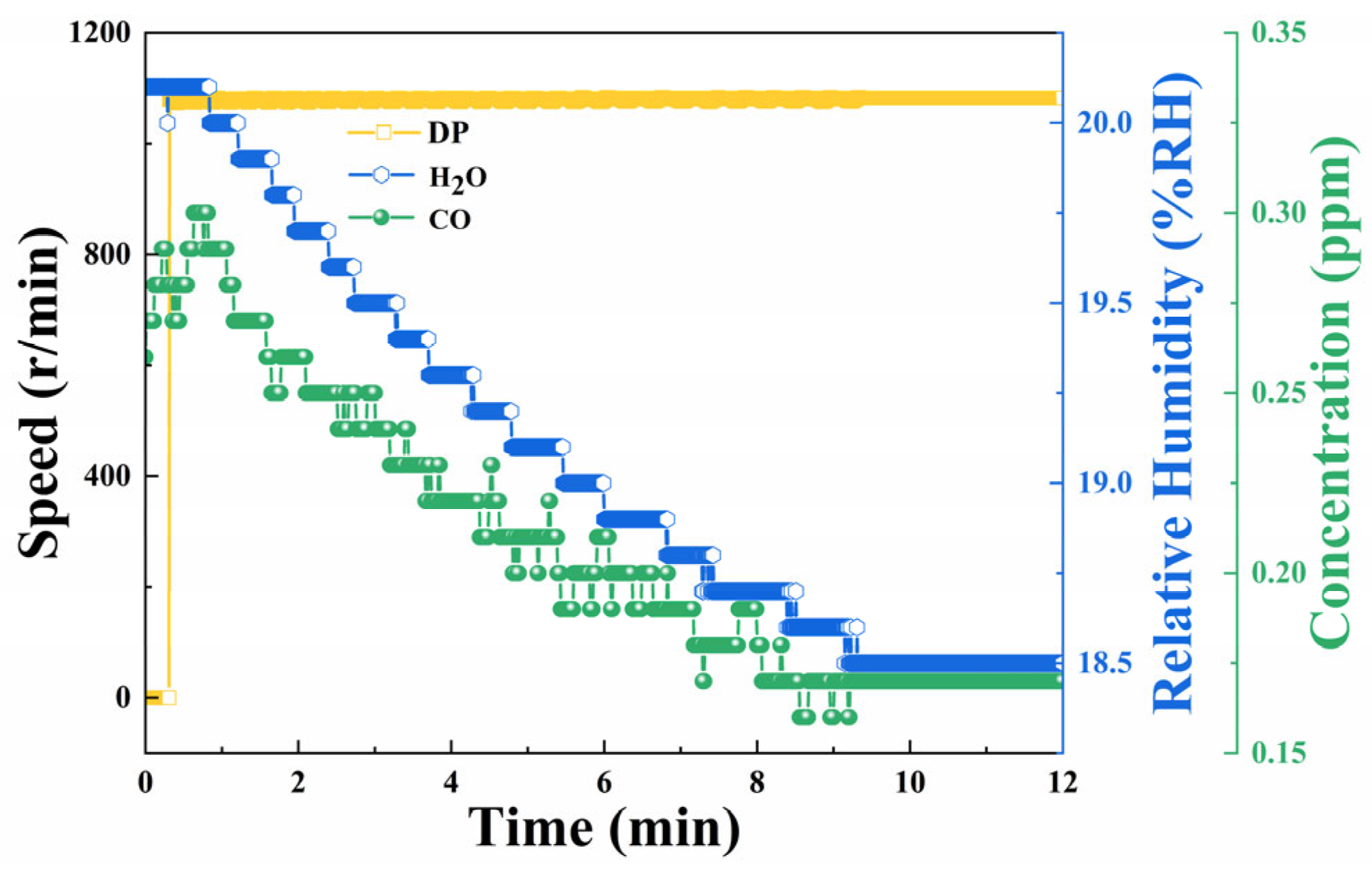
After the flame extinction, the filtration diaphragm pump assumed the critical task of collecting, filtering, and purifying the experimental byproducts. The diaphragm pump operated at a constant speed of 1080 revolutions per minute (1080 r/min), ensuring efficient and stable waste gas treatment. During this process, the concentrations of carbon monoxide (CO) and water (H2O) humidity are monitored in real-time shown in Figure 9. As the diaphragm pump continued to operate, both the CO concentration and H2O humidity gradually decreased, demonstrating the effective progress of the filtration and purification processes. After 10 min of stable operation, the waste gas indicators all meet emission standards, ensuring the safety and environmental sustainability of the experimental system.

4.4. Exhaust Gas Emission and Vacuum Control

To ensure the normal operation of the experimental system and environmental safety, the filtered and purified waste gas meeting emission standards should be promptly discharged from the chamber after the combustion. Following the waste gas discharge, high-purity N2 was used to restore the combustion chamber’s pressure environment. The exhaust and refilling process was repeated to ensure complete gas replacement within the combustion chamber, preventing residual gasses from interfering with subsequent experiments. During this process, the N2 flow rate is set to 5 L per minute (5 L/min), with the inflow data shown in Figure 10. The rate of vacuum-exhausted waste gas decreases progressively, with a higher rate between 1 atm and 0.5 atm and a gradually slower rate between 0.5 atm and 0.01 atm. The pressure increased in the combustion chamber varied linearly with filling time, and the consistency in the trends of multiple fillings demonstrated the stability and reliability of the inflow system. In addition, the remaining volume of the combustion chamber after installing the gas experimental plugin was 70 L through calculation. Based on the flow parameters fed back by the mass flow controller, it has been confirmed that the mass flow of each working substance is effectively controlled, and the gas supply system operates normally. The result verified the rationality of the system’s gas supply design and control logic, providing a reliable chamber for the microgravity combustion experiments on orbit.

5. Conclusions

In this paper, we presented the overall design and operational principles of the CSES established on the CSS and on-orbit verification of the system’s functional completeness, as well as the accuracy and scientific validity of the experimental process. The CSES has demonstrated strong performance under orbital conditions, achieving fully automated experimental operations through electronic control from gas supply, combustion ignition, data collection, to experiment termination. The system is equipped with multiple sensors to monitor key parameters such as combustion chamber pressure, temperature, humidity, and gas concentration in real time, ensuring the safety and controllability of the experimental process. By leveraging the in-cabin spatial environmental conditions provided by the crewed space station, as well as the crew’s on-orbit operation, maintenance, and replacement capabilities, the system utilized external resources including electromechanical, thermal, information, telemetry, nitrogen, vacuum, and exhaust systems. These resources provided the necessary conditions for conducting long-duration microgravity combustion experiments in a limited closed space environment. Currently, the system operates stably in orbit with a good operational status. These will hold significant importance for advancing the development of combustion fundamentals, innovative combustion technologies, and spacecraft fire safety.

Author Contributions

Conceptualization, H.Z. and P.Z.; methodology, P.Z. and X.Z.; validation, P.Z., X.Z. and Y.F.; formal analysis, visualization, P.Z. and Y.F.; investigation, data curation X.Z. and H.W.; writing—original draft preparation, P.Z.; writing—review and editing, P.Z., X.Z., H.Z. and X.Y.; supervision, H.Z.; project administration, X.Y.; funding acquisition, H.Z. All authors have read and agreed to the published version of the manuscript.

Funding

This research received no external funding.

Data Availability Statement

The data presented in this study are available on reasonable request from the corresponding author due to data confidentiality restrictions.

Acknowledgments

The authors sincerely appreciate the support provided by the China Space Station Combustion Science Experimental System Project.

Conflicts of Interest

The authors declare no conflicts of interest.

References

  1. Correa, S.M. Power Generation and Aeropropulsion Gas Turbines: From Combustion Science to Combustion Technology. Symp. Int. Combust. 1998, 27, 1793–1807. [Google Scholar] [CrossRef]
  2. Fernandez-Pello, A.C. Micropower Generation Using Combustion: Issues and Approaches. Proc. Combust. Inst. 2002, 29, 883–899. [Google Scholar] [CrossRef]
  3. Sehra, A.K.; Whitlow, W. Propulsion and Power for 21st Century Aviation. Prog. Aerosp. Sci. 2004, 40, 199–235. [Google Scholar] [CrossRef]
  4. Kohse-Höinghaus, K. Combustion, Chemistry, and Carbon Neutrality. Chem. Rev. 2023, 123, 5139–5219. [Google Scholar] [CrossRef] [PubMed]
  5. Aldushin, A.P.; Matkowsky, B.J.; Schult, D.A. Buoyancy Driven Filtration Combustion. Combust. Sci. Technol. 1997, 125, 283–349. [Google Scholar] [CrossRef]
  6. Jiang, X.; Luo, K.H. Combustion-Induced Buoyancy Effects of an Axisymmetric Reactive Plume. Proc. Combust. Inst. 2000, 28, 1989–1995. [Google Scholar] [CrossRef]
  7. Bar-Ilan, A.; Rein, G.; Walther, D.C.; Fernandez-Pello, A.C.; Torero, J.L.; Urban, D.L. The Effect of Buoyancy on Opposed Smoldering. Combust. Sci. Technol. 2004, 176, 2027–2055. [Google Scholar] [CrossRef]
  8. King, M.K.; Ross, H.D. Overview of the NASA Microgravity Combustion Program. AIAA J. 1998, 36, 1337–1345. [Google Scholar] [CrossRef]
  9. Wu, C.; Xiao, Y.; Wang, S.; Zhu, F. Horizontal Flame Spread over Thin Solids in Reduced Buoyancy Environments. Combust. Flame 2022, 240, 112008. [Google Scholar] [CrossRef]
  10. Huang, X.; Nakamura, Y.; Urban, D. Introduction to Special Issue on Spacecraft Fire Safety. Fire Technol. 2020, 56, 1–4. [Google Scholar] [CrossRef]
  11. Jomaas, G.; Torero, J.L.; Eigenbrod, C.; Niehaus, J.; Olson, S.L.; Ferkul, P.V.; Legros, G.; Fernandez-Pello, A.C.; Cowlard, A.J.; Rouvreau, S.; et al. Fire Safety in Space–beyond Flammability Testing of Small Samples. Acta Astronaut. 2015, 109, 208–216. [Google Scholar] [CrossRef]
  12. Friedman, R.; Sacksteder, K. Science and Technology Issues in Spacecraft Fire Safety. In 25th AIAA Aerospace Sciences Meeting; American Institute of Aeronautics and Astronautics: Reston, VA, USA, 12–15 January 1987. [Google Scholar]
  13. Li, N.; Deng, H.; Xu, Z.; Yan, M.; Wei, S.; Sun, G.; Wen, X.; Gan, H.; Wang, F. Effect of Oxygen-Rich Combustion on Flame Propagation of Syngas in a Half-Open Pipe at Elevated Temperatures. J. Therm. Sci. 2024, 33, 1920–1934. [Google Scholar] [CrossRef]
  14. Li, D.; Wen, Y.; Liu, Y.C.; Wang, S. On the Transition Modes and Mechanisms for Laminar to Turbulent Lifted Jet Diffusion Flames at Normal- and Micro-Gravity. Combust. Flame 2024, 260, 113269. [Google Scholar] [CrossRef]
  15. Nakamura, Y.; Usuki, T.; Wakatsuki, K. Novel Fire Extinguisher Method Using Vacuuming Force Applicable to Space Habitats. Fire Technol. 2020, 56, 361–384. [Google Scholar] [CrossRef]
  16. Torikai, H. Extinguishing Characteristics of a Pool Fire with a Rubber Balloon Filled with Inert Gases. Fire Technol. 2020, 56, 385–399. [Google Scholar] [CrossRef]
  17. Takahashi, J.; Fujita, O.; Ito, K. The Effect of Irradiation Angle on Laser Ignition of Cellulose Sheet in Microgravity. Proc. Combust. Inst. 2005, 30, 2311–2317. [Google Scholar] [CrossRef]
  18. Protsch, R.W. EUROTUBE-SAAR: A European Drop Shaft Facility. Adv. Space Res. 1991, 11, 119–121. [Google Scholar] [CrossRef]
  19. Olson, S.L. Piloted Ignition Delay Times of Opposed and Concurrent Flame Spread over a Thermally-Thin Fuel in a Forced Convective Microgravity Environment. Proc. Combust. Inst. 2011, 33, 2633–2639. [Google Scholar] [CrossRef]
  20. Roslon, M.; Olenick, S.; Zhou, Y.Y.; Walther, D.C.; Torero, J.L.; Fernandez-Pello, A.C.; Ross, H.D. Microgravity Ignition Delay of Solid Fuels in Low-Velocity Flows. AIAA J. 2001, 39, 2336–2342. [Google Scholar] [CrossRef]
  21. van Wynsberghe, E.; Turak, A. Station-Keeping of a High-Altitude Balloon with Electric Propulsion and Wireless Power Transmission: A Concept Study. Acta Astronaut. 2016, 128, 616–627. [Google Scholar] [CrossRef]
  22. Olson, S.L.; Hegde, U.; Bhattacharjee, S.; Deering, J.L.; Tang, L.; Altenkirch, R.A. Sounding rocket microgravity experiments elucidating diffusive and radiative transport effects on flame spread over thermally thick solids. Combust. Sci. Technol. 2004, 176, 557–584. [Google Scholar] [CrossRef]
  23. Olson, S.L.; Ferkul, P.V. Microgravity Flammability Boundary for PMMA Rods in Axial Stagnation Flow: Experimental Results and Energy Balance Analyses. Combust. Flame 2017, 180, 217–229. [Google Scholar] [CrossRef]
  24. Olson, S.L.; Kashiwagi, T.; Fujita, O.; Kikuchi, M.; Ito, K. Experimental Observations of Spot Radiative Ignition and Subsequent Three-Dimensional Flame Spread over Thin Cellulose Fuels. Combust. Flame 2001, 125, 852–864. [Google Scholar] [CrossRef]
  25. Urban, D.L.; Ferkul, P.; Olson, S.; Ruff, G.A.; Easton, J.; T’ien, J.S.; Liao, Y.-T.T.; Li, C.; Fernandez-Pello, C.; Torero, J.L.; et al. Flame Spread: Effects of Microgravity and Scale. Combust. Flame 2019, 199, 168–182. [Google Scholar] [CrossRef]
  26. Xue, T.; Liang, D.; Pang, W.; Shen, D.; Niamat, A.; Liu, J.; Zhou, J. Ignition and Combustion of Metal Fuels under Microgravity: A Short Review. FirePhysChem 2022, 2, 340–356. [Google Scholar] [CrossRef]
  27. Dittus, H. Drop Tower ‘Bremen’: A Weightlessness Laboratory on Earth. Endeavour 1991, 15, 72–78. [Google Scholar] [CrossRef]
  28. Rojas-Alva, U.; Jomaas, G. A Historical Overview of Experimental Solid Combustion Research in Microgravity. Acta Astronaut. 2022, 194, 363–375. [Google Scholar] [CrossRef]
  29. Matsumoto, K.; Fujii, T.; Suzuki, K.; Segawa, D.; Kadota, T. Laser-Induced Fluorescence for the Non-Intrusive Diagnostics of a Fuel Droplet Burning under Microgravity in a Drop Shaft. Meas. Sci. Technol. 1999, 10, 853. [Google Scholar] [CrossRef]
  30. Mikami, M.; Matsumoto, K.; Yoshida, Y.; Kikuchi, M.; Dietrich, D.L. Space-Based Microgravity Experiments on Flame Spread over Randomly Distributed n-Decane-Droplet Clouds: Anomalous Behavior in Flame Spread. Proc. Combust. Inst. 2021, 38, 3167–3174. [Google Scholar] [CrossRef]
  31. Nayagam, V.; Dietrich, D.L.; Ferkul, P.V.; Hicks, M.C.; Williams, F.A. Can Cool Flames Support Quasi-Steady Alkane Droplet Burning? Combust. Flame 2012, 159, 3583–3588. [Google Scholar] [CrossRef]
  32. Moura, W.D.M.; Dos Santos, C.R.; Freitas, M.J.D.S.; Pinto, A.C.; Simões, L.P.; Moraes, A. MicroGravity Explorer Kit (MGX): An Open-Source Platform for Accessible Space Science Experiments. Aerospace 2024, 11, 790. [Google Scholar] [CrossRef]
  33. Liu, B.; Zhang, Z.; Zhang, H.; Zhang, D. Volatile Release and Ignition Behaviors of Single Coal Particles at Different Oxygen Concentrations Under Microgravity. Microgravity Sci. Technol. 2016, 28, 101–108. [Google Scholar] [CrossRef]
  34. Wang, S.; Hu, J.; Xiao, Y.; Ren, T.; Zhu, F. Opposed-Flow Flame Spread Over Solid Fuels in Microgravity: The Effect of Confined Spaces. Microgravity Sci. Technol. 2015, 27, 329–336. [Google Scholar] [CrossRef]
  35. Wu, C.; Sun, P.; Wang, X.; Huang, X.; Wang, S. Flame Extinction of Spherical PMMA in Microgravity: Effect of Fuel Diameter and Conduction. Microgravity Sci. Technol. 2020, 32, 1065–1075. [Google Scholar] [CrossRef]
  36. Sun, P.; Wu, C.; Zhu, F.; Wang, S.; Huang, X. Microgravity Combustion of Polyethylene Droplet in Drop Tower. Combust. Flame 2020, 222, 18–26. [Google Scholar] [CrossRef]
  37. Zhu, F.; Huang, X.; Wang, S. Flame Spread over Polyethylene Film: Effects of Gravity and Fuel Inclination. Microgravity Sci. Technol. 2022, 34, 26. [Google Scholar] [CrossRef]
  38. Cai, G.; Liu, L.; He, B.; Ling, G.; Weng, H.; Wang, W. A Review of Research on the Vacuum Plume. Aerospace 2022, 9, 706. [Google Scholar] [CrossRef]
  39. Dong, W.; Duan, W.; Liu, W.; Zhang, Y. Microgravity Disturbance Analysis on Chinese Space Laboratory. NPJ Microgravity 2019, 5, 18. [Google Scholar] [CrossRef]
  40. Shen, G.; Zhang, S.; Zhang, X.; Zhang, H.; Yuan, B.; Hou, D.; Wang, C.; Quan, Z.; Yang, Z.; Sun, Y. Using Energy Particle Detection Technology on the Tiangong’s Space Station’s Wentian Laboratory Cabin Module. Aerospace 2023, 10, 373. [Google Scholar] [CrossRef]
  41. Shi, K.; Yang, H.; Zhang, W.; Chen, W.; Yan, A.; Peng, J. Research on a New Multifunctional Cell Sample Automatic Culture Device for Use in the Chinese Space Station. Aerospace 2025, 12, 90. [Google Scholar] [CrossRef]
  42. Wang, Y.; Zou, T.; Guo, L.; Zhang, C.; Zhang, L. Design and Implementation of a Generalized Safety Fault Diagnosis System for China Space Station Scientific Experimental Rack. Sensors 2024, 24, 5102. [Google Scholar] [CrossRef] [PubMed]
  43. Wang, J.; Chen, Y.; Wu, D.; Hu, L.; Ye, Z.; Duan, L.; Zhao, X.; Yin, Y.; Kang, Q. Development and Space Experiment Verification of Annular Liquid Flow Payload for China Space Station. Symmetry 2024, 16, 1530. [Google Scholar] [CrossRef]
  44. Wang, X.; Zhang, Q.; Wang, W. Design and Application Prospect of China’s Tiangong Space Station. Space Sci. Technol. 2023, 3, 0035. [Google Scholar] [CrossRef]
  45. Wu, W.; Zou, T.; Guo, D.; Zhang, L.; Wang, K.; Li, X. Fault Diagnosis for China Space Station Circulating Pumps: Prototypical Network with Uncertainty Theory. Symmetry 2023, 15, 903. [Google Scholar] [CrossRef]
  46. Wu, S.; Yan, H.; Zhao, Y.; Chen, Y.; Tang, G. A Framework for Rapidly Predicting the Dynamics of Flexible Solar Arrays in the China Space Station with a Verification Based on On-Orbit Measurement Data. Aerospace 2024, 11, 411. [Google Scholar] [CrossRef]
  47. Zhang, J.; Zhu, Y.; Luo, Y. Optimization for Overall Planning of Space-Station on-Orbit Activities and Logistics. Acta Astronaut. 2021, 186, 211–227. [Google Scholar] [CrossRef]
  48. Zhang, Z.; Kong, W.; Zhang, H. Design of Combustion Science Experimental System for China Space Station. Chin. J. Space Sci. 2020, 40, 72. [Google Scholar] [CrossRef]
  49. He, L.; Zheng, H.; Wang, X.; Yang, X.; Zhang, X. Ground Experiment Investigation of PIV Unit for Combustion Science Experimental System of China Space Station. Chin. J. Space Sci. 2022, 42, 1152. [Google Scholar] [CrossRef]
  50. Peng, X.; Zheng, H.; Fang, Y.; Lan, X.; Yang, X.; Zhang, X. Numerical Simulation Study on the Feasibility of Cyclone PIV Tracer Particle Seeder in Microgravity. Energies 2025, 18, 1700. [Google Scholar] [CrossRef]
  51. Fang, Y.; Zheng, H.; Peng, X.; Zhang, X. Dimensional Homogeneity-Based Motion and Tracking Analysis of Tracer Particles in an Actual Combustion Flow. Appl. Therm. Eng. 2025, 269, 125965. [Google Scholar] [CrossRef]
  52. Wen, Y.; Li, L.; Li, X.; Luo, L.; Chen, T.; Zhang, W.; Zhou, H.; Chen, S.; Sun, Y.; Shi, J.; et al. Extinction of Microgravity Partially Premixed Flame Aboard the Chinese Space Station. Proc. Combust. Inst. 2024, 40, 105574. [Google Scholar] [CrossRef]
Figure 1. Schematic diagram of the overall layout of the CSES.
Aerospace 12 00448 g001
Figure 2. Structure and layout of the CSES. The right panel in presents the rear view of the left panel, where the optical diagnostic equipment is indicated by a red arrow with its number.
Aerospace 12 00448 g002
Figure 3. Interface between subsystems of the CSES.
Aerospace 12 00448 g003
Figure 4. Operating modes of the CSES.
Aerospace 12 00448 g004
Figure 5. Ignition test procedure.
Aerospace 12 00448 g005
Figure 6. Gas combustion operation process on-orbit.
Aerospace 12 00448 g006
Figure 7. Supply of (a) O2 and N2 for configuring the environmental atmosphere and (b) CH4 and O2 for igniting on-orbit.
Aerospace 12 00448 g007
Figure 8. The (a) digital signal and (b) image of ignition.
Aerospace 12 00448 g008
Figure 9. The content of CO and H2O under the diaphragm pump (DP) operating at a constant speed of 1080 r/min.
Aerospace 12 00448 g009
Figure 10. Combustion chamber pressure during circulating exhaust and N2 supply. Specifically: Combustion chamber pressure (gray) during circulating exhaust and N2 (blue) supply.
Aerospace 12 00448 g010
Table 1. Technical indicator and implementation of the CSES.
IndicatorValue
Weight265.7 kg
Dimension944 mm × 752 mm × 1100 mm
Power100 V DC<1200 W
28 V DC<1200 W
CommunicationEthernet protocol
RS422
≮600 Mbps
115,200 ± 3% bps
Combustion chamberVolume
Pressure
70 L
0.01~0.30 Mpa
Gas supplyFlow rate0~2 SLM (O2, Fuel), 0~5 SLM (N2, Ar)
Precision±(0.4% of reading + 0.2% of range)
Table 2. Camera properties of the combustion diagnostic subsystem in the CSES.
DeviceResolution
(Pixels)
Frame Rate
(fps)
Pixel Size
(μm2)
Spectral Range (nm)Spectrum
1, 4, 61296 × 1024308611 × 11290~1100Color
3, 81280 × 10244910 × 10200~900Mono
71296 × 1024308611 × 11290~1100Mono
Table 3. The technical parameters of combustion facilities in ISS and CSS.
ProjectISSCSS
Experimental Conditions300 K, 0.02~0.30 MPa300 K, 0.02~0.30 MPa
Color camera640 × 480 (30 fps), Qty 11296 × 1024 (3086 fps), Qty 3
Mono camera1024 × 1024 (30 fps), Qty 11296 × 1024 (3086 fps), Qty 1
Special cameraLow light level IR camera, Qty 1
Low light level UV camera, Qty 1
ICCD, Qty 2
Light10 mW LED, Qty 120 W Continuous laser, Qty 1
10 W Collimated light, Qty 1
Optical diagnostics of pluginThermal radiometers, Qty 5
Photomultiplier, Qty 3
Monitoring camera
Thermal radiometers, Qty 2
Photomultiplier, Qty 3
Wide-angle camera
Other functions of pluginReplaceable burner
Retractable heating wire
Thin-filament flame thermometry
Electric field generator
Replaceable burner
Retractable heating wire
Environmental monitoring and alarm
Particle protection
Disclaimer/Publisher’s Note: The statements, opinions and data contained in all publications are solely those of the individual author(s) and contributor(s) and not of MDPI and/or the editor(s). MDPI and/or the editor(s) disclaim responsibility for any injury to people or property resulting from any ideas, methods, instructions or products referred to in the content.