Article

Flexible Surface Reflector Antenna for Small Satellites

1
Mechanical R&D (Space System), LIG Nex1, Seongnam 13488, Republic of Korea
2
Department of Aeronautical and Astronautical Engineering, Korea Aerospace University, Goyang 10540, Republic of Korea
3
Department of Electronics, Telecommunications and Computer Engineering, Korea Aerospace University, Goyang 10540, Republic of Korea
4
HSCUBE Inc., Goyang 10449, Republic of Korea
*
Author to whom correspondence should be addressed.
Aerospace 2025, 12(5), 414; https://doi.org/10.3390/aerospace12050414
Submission received: 4 March 2025 / Revised: 3 May 2025 / Accepted: 5 May 2025 / Published: 7 May 2025
(This article belongs to the Special Issue Advanced Aerospace Composite Materials and Smart Structures)

Abstract

:
A novel deployable reflector antenna for small satellites has been designed, fabricated, and experimentally validated. The reflector utilizes a doubly curved flexible surface manufactured from a triaxially woven fabric-reinforced silicone (TWFS) composite. By leveraging high-strain composite materials, the design enables a highly compact stowed configuration while maintaining precise surface accuracy upon deployment. The deployment mechanism is proposed to accommodate a 0.6 m diameter parabolic reflector within a minimal stowed volume, optimizing space efficiency for satellite integration. To validate this concept, a prototype of the reflector antenna has been fabricated and demonstrated the feasibility and effectiveness of the proposed approach.

1. Introduction

The development of large space structures has been a growing area of research aimed at enhancing spacecraft performance for a wide range of missions. As space structures continue to increase in size, manufacturing and launch costs rise significantly, driving the need for innovative lightweight deployable structures [1]. Research on small satellites equipped with deployable reflector antennas for Earth observation such as weather monitoring, ocean surveillance, and environmental analysis has gained substantial attention.
Deployable antennas for small satellites, particularly CubeSats, are of significant interest due to their ability to achieve high-gain communication while maintaining a compact form factor during launch. The rapid advancements in CubeSat technology have intensified the demand for high-performance deployable reflector antennas to support telecommunication, remote sensing, and scientific missions. Conventional CubeSat antennas are often constrained by their limited size, restricting their ability to achieve high gain and narrow beamwidths. To overcome this limitation, deployable reflector antennas have been designed to maximize the effective aperture while remaining compact in a stowed configuration [2]. Deployable reflector antennas must maintain precise surface accuracy, particularly for high-frequency applications such as Ka-band communications, where surface errors must remain within λ/50 to λ/100 to ensure optimal performance [3]. Several engineering approaches have been explored to achieve high-precision deployable reflectors, including metallic mesh reflectors supported by rigid ribs, as demonstrated in the RainCube mission [4]. Although these systems have been successfully deployed, they are often limited in scalability due to their reliance on numerous mechanical support structures, which increase complexity and stowage volume.
To address these challenges, advanced materials such as carbon-fiber-reinforced silicone (CFRS) and other high-strain composites have been investigated for deployable reflector applications [5]. Recent advancements in shell membrane materials, such as a triaxially woven fabric (TWF) composite, have enabled the development of deployable reflectors that retain their shape upon deployment [6,7,8]. Large-scale TWF composites are characterized by in-plane quasi-isotropic thermo-mechanical behaviors [9]. The inherent isotropy of TWF enables the potential use of a single layer as a composite reinforcement. Additionally, the extremely low aerial density of single-layer TWF composites, attributed to their lattice structure, facilitates the development of ultra-lightweight designs [10,11].
In this study, an innovative deployable reflector antenna for small satellites is designed, fabricated, and experimentally validated. A doubly curved flexible surface reflector is manufactured using a triaxially woven fabric-reinforced silicone (TWFS) composite. The mechanical and electrical properties of the TWFS are characterized experimentally, forming the basis for the reflector’s structural and electromagnetic design. The antenna’s electrical performance is analyzed. A deployment mechanism is introduced, leveraging high-strain TWFS composite materials to achieve a compact stowed volume while ensuring high surface accuracy upon deployment. To demonstrate the feasibility of this approach, a 0.6 m reflector prototype is designed, fabricated, and tested.

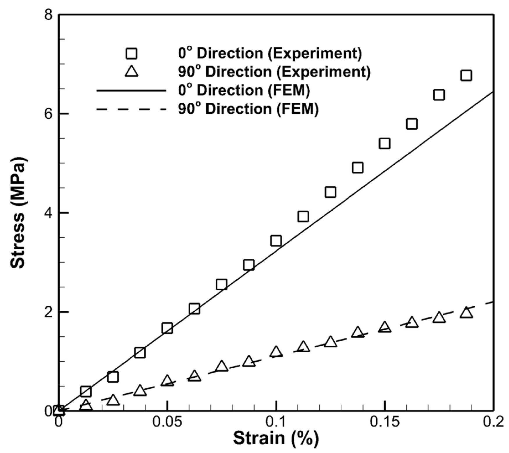
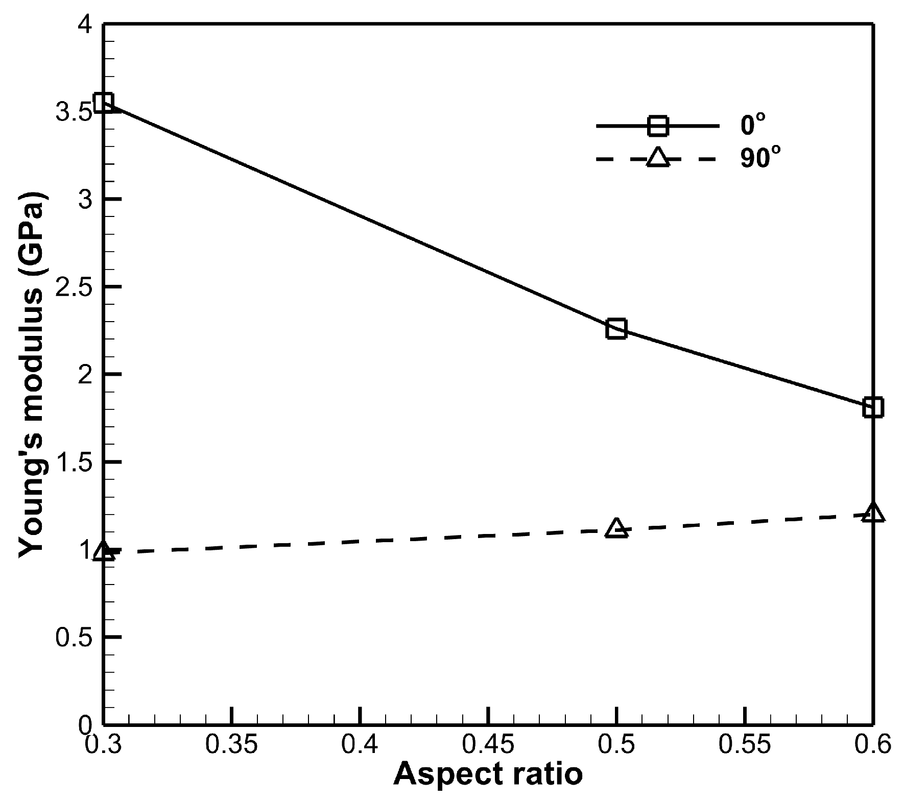
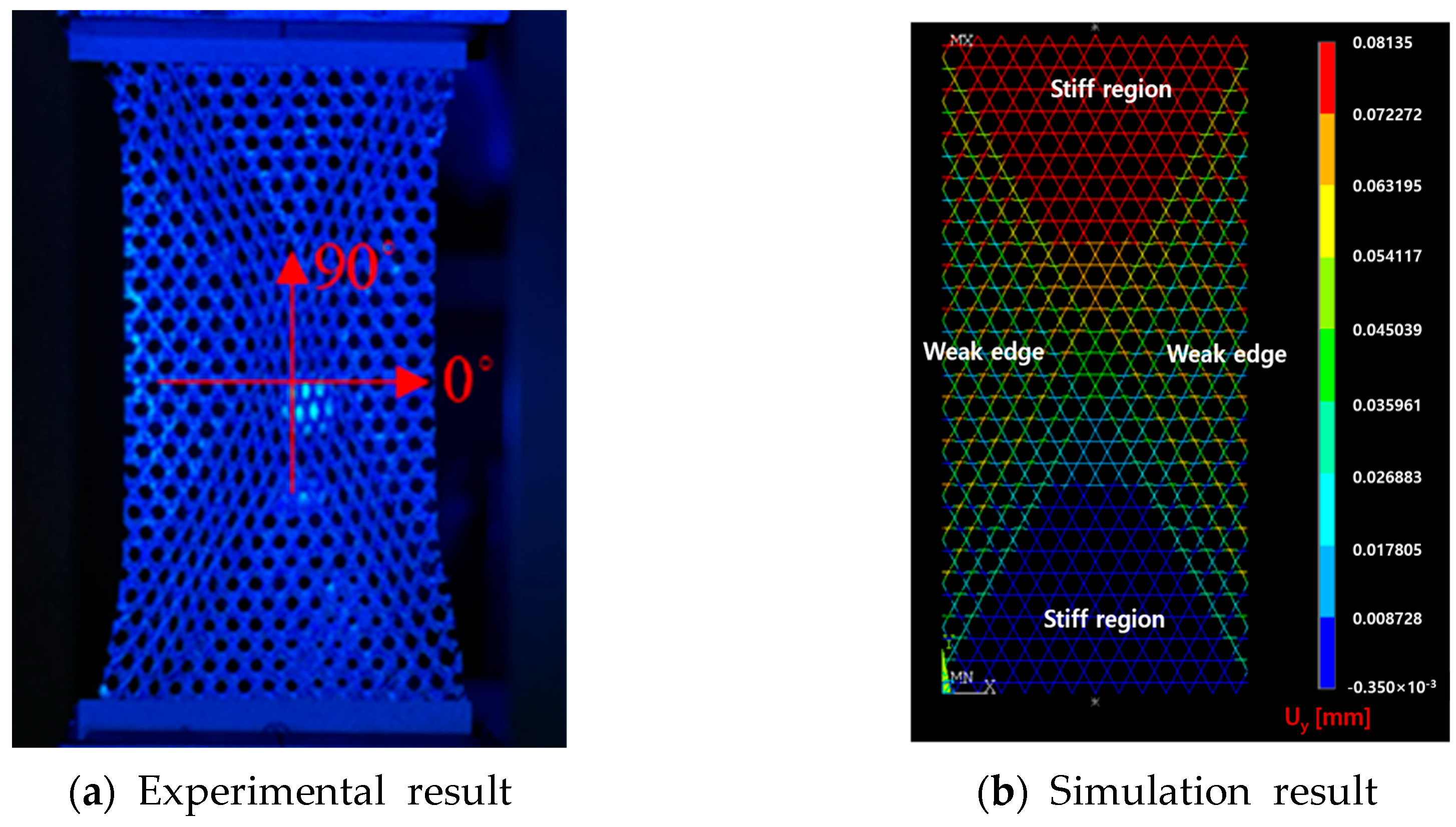
2. Mechanical and Electrical Properties of TWFS Composites

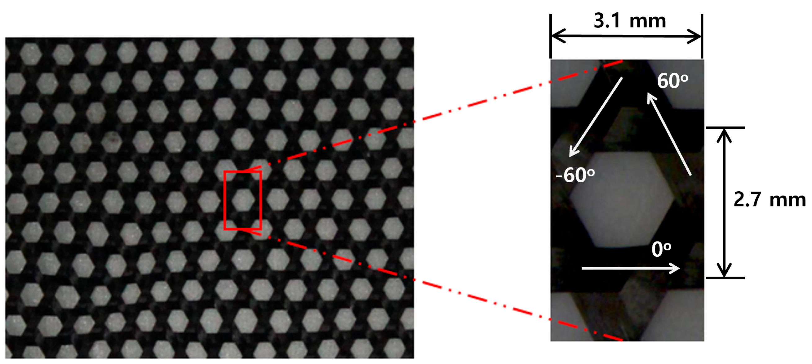
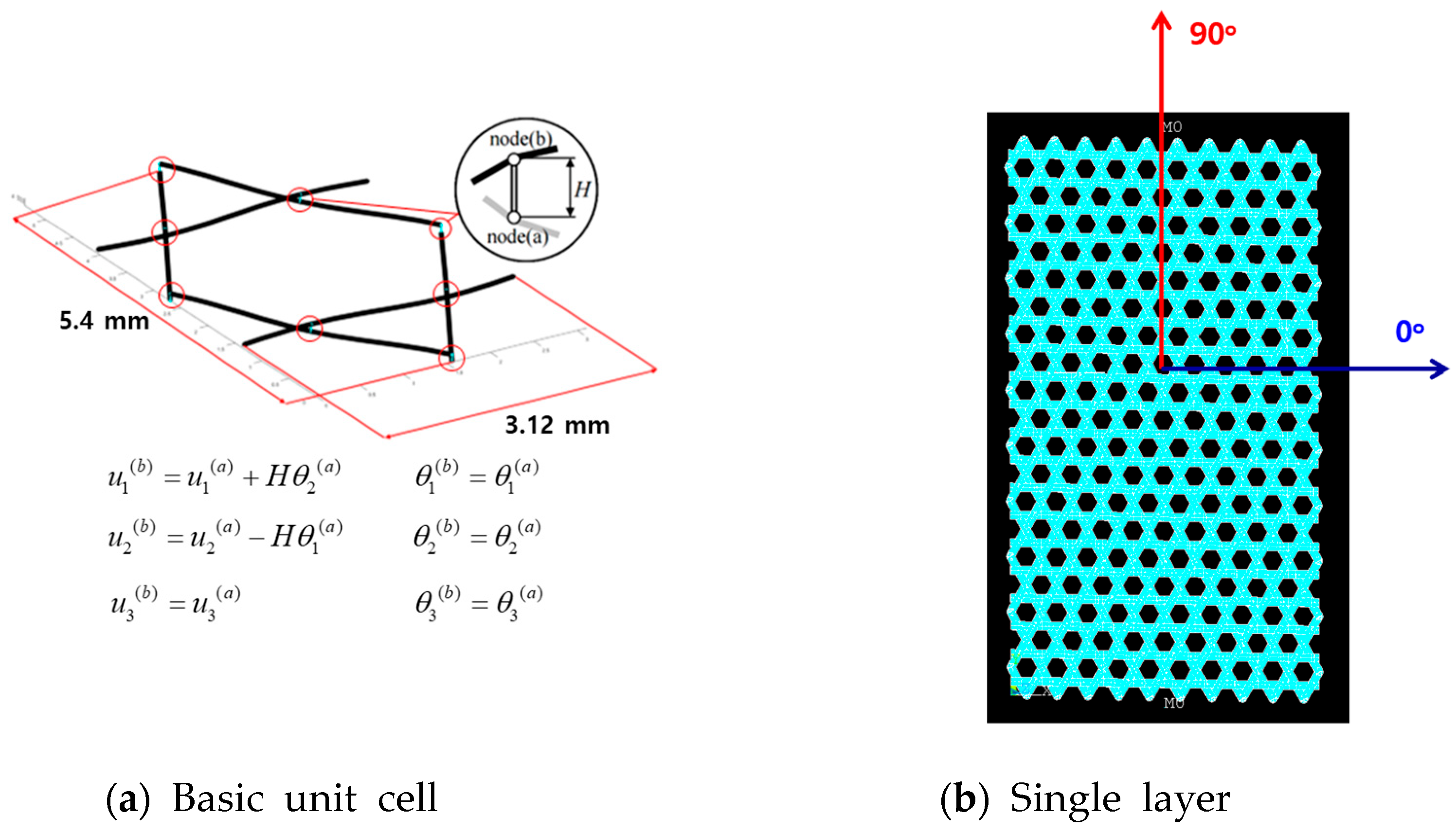
2.1. Fabrication of the TWFS Composite

A flexible surface reflector is composed of two materials: carbon fibers and a silicone elastomer. A triaxially woven carbon T300 fiber fabric of SK-802 is used to reinforce a space-qualified silicone elastomer. The elastomer can be cured at room temperature and gives an advantage of manufacturing large seized doubly curved structures on significantly cheap molds. A basic geometry of the TWFS specimen is shown in Figure 1. This TWF has a dry fabric thickness of 0.13 mm and a dry fiber tow width of 0.9 mm. The manufacturing process for a single layer of TWFS follows basic steps: (1) cutting of a reinforcing material; (2) hand laminating with relatively high viscosity matrix material makes it particularly important to care for the triaxially woven fabrics; (3) applying of a matrix material and impregnation of the reinforcing material; and (4) curing of the composite at room temperature.
The high flexibility of the TWFS calls for the development of special methods and tools for testing, as well as for the analysis of mechanical properties for its characterization. The uniaxial tensile test is performed following the standard test method for the tensile properties of plastics [12]. The use of standard strain measurement techniques is complicated and sometimes not possible due to the very low stiffness of the silicone; it is much lower than that of the strain gauges, and the attachment of extensometers to the TWFS surface is not reliable. So, a 3D strain measurement system, ARAMIS [13], is used for measuring the strain. Figure 2 shows the experimental setup for tensile tests. ARAMIS measures the deformation of the specimen during the tensile tests. The strain was calculated using the ARAMIS software(v.2023.5.0.188) based on the initial specimen length and deformation data measured by the ARAMIS system. The force data obtained from the tensile testing machine were used to calculate the nominal stress. The effective modulus of the TWFS specimen was subsequently determined from the linear region of the stress–strain curve.
In the numerical models of TWF composites, the crossing tows have to be modeled separately from each other due to the line (beam) element geometry. The beam element has a rectangular cross-section with a width of 0.9 mm and a thickness of 0.13 mm. Then, accurate connection modeling and calculating of the two properties from that micro-laminate of the composite is necessary for the model. Table 1 presents the mechanical properties of the tow estimated using the rule of mixtures and the Halpin–Tsai semi-empirical model [10,11]. For TWF composites with stiff matrix materials, several different possibilities (coupling, rigid beam) were used for tow-to-tow connection modeling [14,15,16]. The unit cell of the TWF is modeled as a two-dimensional lattice of beams. Beam elements are used to model the tow-to-tow connections. To idealize perfect bonding conditions at the tow crossover areas, rigid beam constraints are applied to the tow-to-tow connection beam elements (Figure 3a). Here, u and θ represent the translational and rotational degrees of freedom of the nodes, respectively. The subscripts 1, 2, and 3 correspond to the x-, y-, and z-directions, while the superscripts a and b denote the two nodes of each connection beam element. H represents the distance between the nodes, corresponding to half the thickness of the unit cell. A basic unit consists of one hexagonal cell and two triangles, and it repeats several times in 0° and 90° directions (Figure 3b). The single-layer structure is composed of a periodically repeated unit cell in the 0° and 90° directions, wherein each unit shares nodal points with adjacent cells to ensure structural continuity. The lateral (left and right) edges are modeled as free boundaries, while the upper and lower edges—where external loads are applied—are constrained using rigid body elements, each incorporating a single independent node to facilitate uniform displacement.
Generally, triaxial woven fabrics are expected to exhibit quasi-isotropic mechanical properties due to their repetitive geometric pattern [17]. However, as shown in Figure 4, the modulus in the 0° direction is significantly higher than that in the orthogonal 90° direction. So, we conduct a more investigation into the mechanical properties as a function of the specimen’s aspect ratio. The test results are summarized in Figure 5. The modulus in the 90° direction is initially lower than that in the 0° direction. As the aspect ratio increases, a reduction in the modulus of the 0° direction is observed, while a slight increase occurs in the 90° direction. These results are attributed to the geometric discontinuities of the +60° and −60° oriented fibers near the specimen edge under 90° directional loading [18]. As the number of unit cells increases in the transverse direction, the material approaches quasi-isotropic behavior. However, the mechanical properties vary depending on the specimen size. Figure 6 illustrates the deformed shape of the specimen under 90° directional loading, with a specimen size of 41 mm × 81 mm. When loading is applied along the 90° direction, the load is primarily distributed along the ±60° fiber orientations. As a result, stiff regions develop near the fixed boundaries, while the effects of weaknesses at the free edges become more pronounced. Ultimately, an X-shaped deformation is consistently observed both experimentally and numerically.

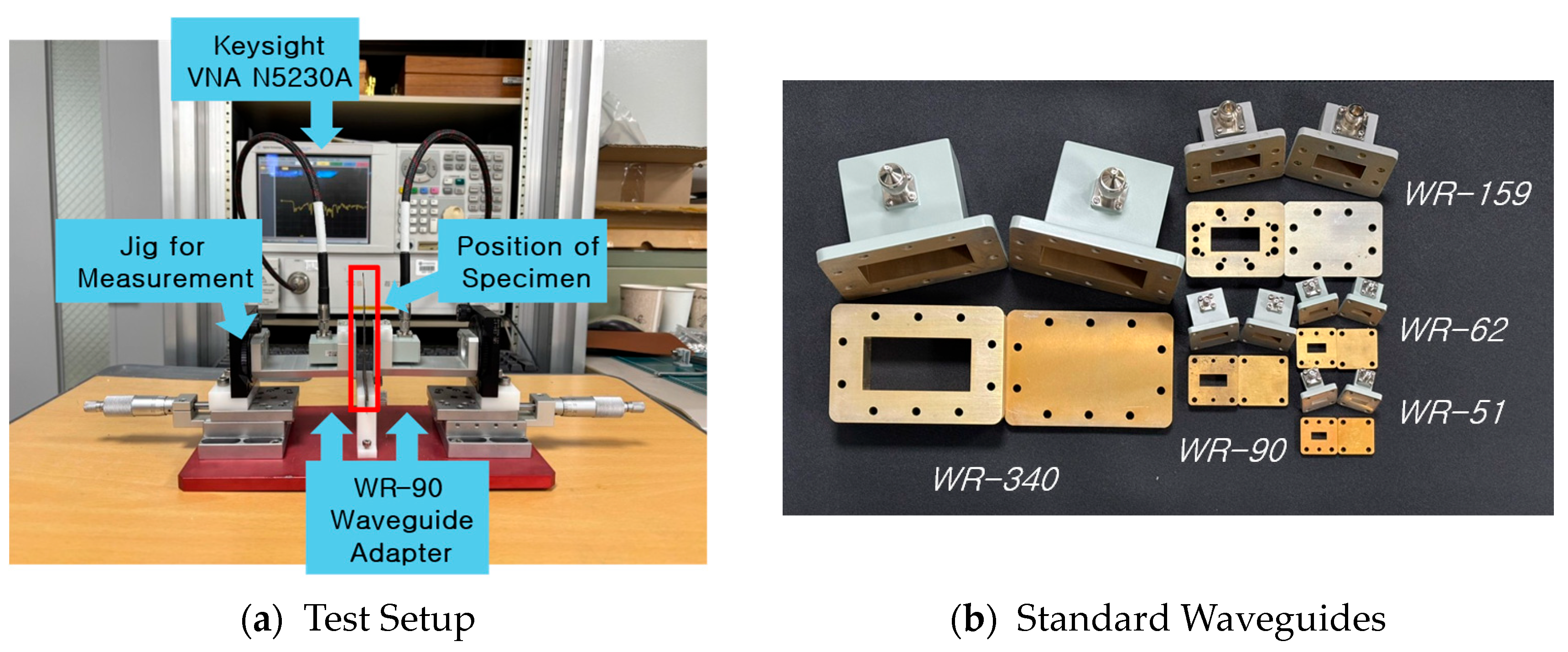
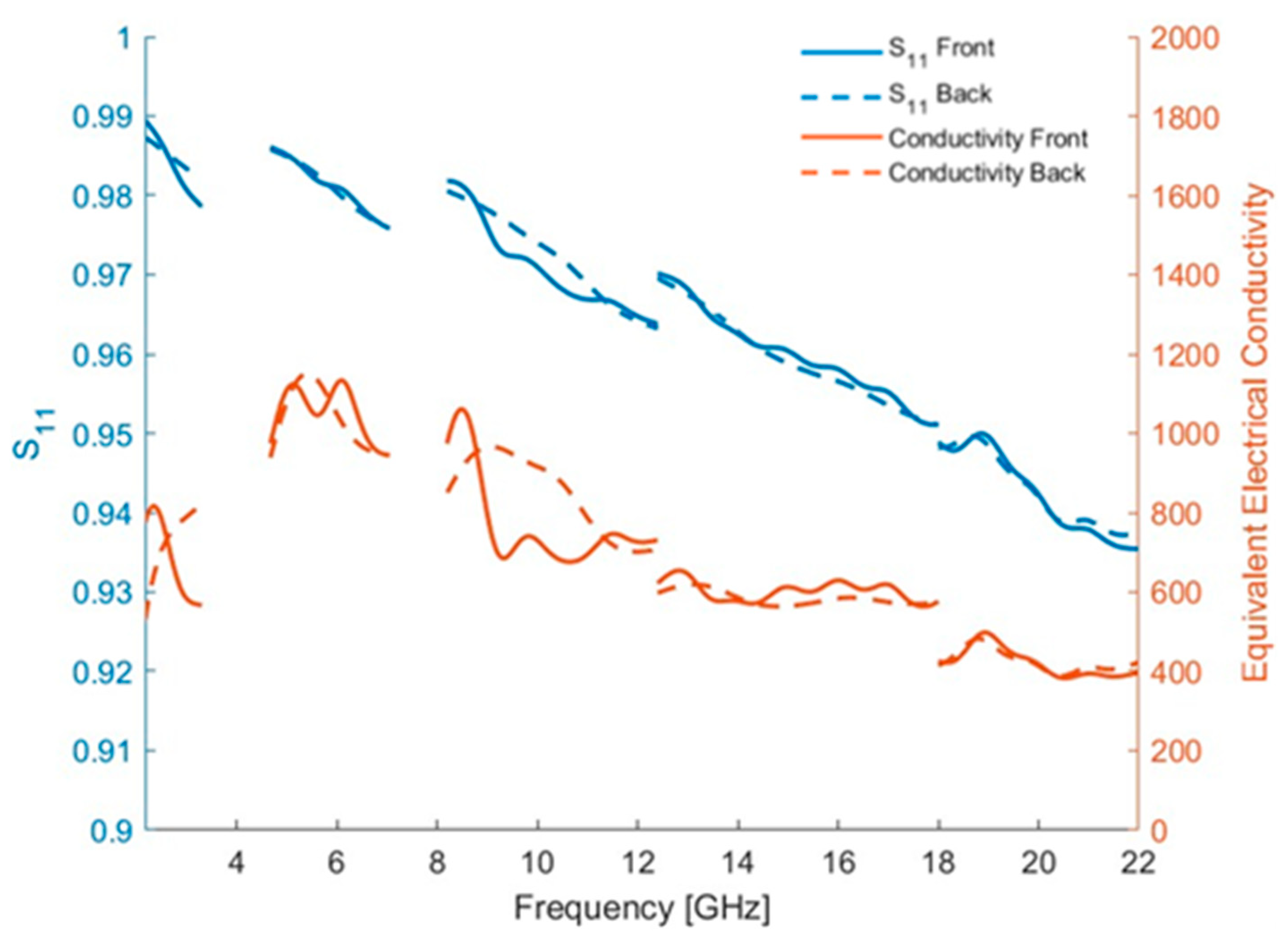
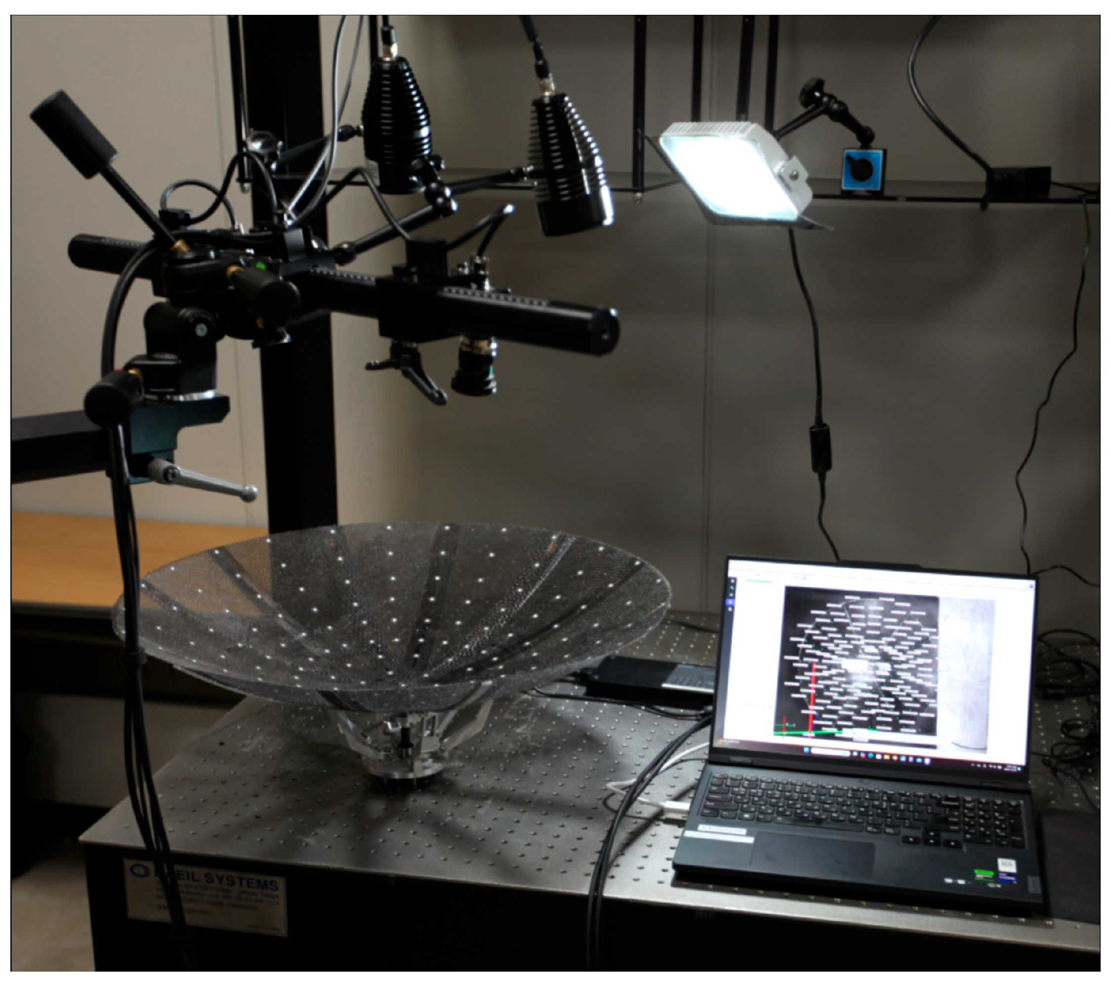
2.2. Electrical Properties of the TWFS

The electrical properties of the target specimens are modeled as uniformly effective bulk materials, represented by effective complex permittivity (εs) or effective permeability (μs). These effective values, εs and μs, were obtained by applying the measured S-parameters to the Nicolson–Ross theory.
The equivalent electrical conductivity of the TWFS composite can be determined using the transmission line method by analyzing the configuration in which a specimen is placed in contact with the open end of a waveguide [19]. In this setup, the scattering parameter defined as the ratio of the incident electric field to the reflected electric field is measured. Specifically, the scattering parameter(S₁₁) was measured using a two-port vector network analyzer (VNA), which transmits electromagnetic waves at various frequencies into a specimen positioned tightly against the waveguide aperture. The VNA precisely records both the magnitude and phase information of the reflected wave signals.
The magnitude of the measured scattering parameter and the equivalent electrical conductivity are related as expressed in Equation (1), which is derived based on the reflection characteristics of electromagnetic waves at the specimen–waveguide interface:
σ = 4 π μ o f 1 S 11 2 2 Z w 2 1 + S 11 2 S 11 4 + 6 S 11 2 1 2
In this equation, σ denotes the equivalent electrical conductivity of the composite (S/m). The constant μ₀ represents the permeability of free space (4π × 10⁻⁷ H/m), and f is the frequency (Hz) of the electromagnetic wave used during measurement. |S₁₁| indicates the magnitude of the measured scattering parameter, representing how strongly the specimen reflects incident electromagnetic waves at each frequency. Zw corresponds to the wave impedance of the waveguide, a standard constant determined by the waveguide’s geometric dimensions and operating frequency range.
Figure 7 depicts the measurement concept and experimental configuration using a rectangular waveguide. To characterize the electrical properties of the samples, we utilize a two-port vector network analyzer (VNA) N5230A (Keysight Technology, Santa Rosa, CA, USA) to measure S-parameters within an air-filled rectangular waveguide. To achieve broadband frequency measurements and accurately characterize the frequency-dependent behavior of the TWFS composite, multiple standardized waveguides were employed rather than relying solely on a single WR-90 waveguide. As shown in Figure 7b, a series of standard rectangular waveguides (WR-340, WR-159, WR-90, WR-62, and WR-51) were systematically utilized, covering a broad frequency range from approximately 2 GHz to 30 GHz. This approach enabled a detailed investigation of the electrical properties across a wide spectrum of microwave frequencies, providing comprehensive insight into the performance characteristics of the composite material.
The specimen exhibited high equivalent electrical conductivity, demonstrating values around 1000 S/m at lower frequencies (Figure 8). However, as the frequency increased to 20 GHz, the conductivity decreased to approximately 400 S/m. These results confirm that the specimen maintains stable and favorable electrical properties across the measured frequency range. The decrease in electrical conductivity at higher frequencies is primarily attributed to dielectric dispersion phenomena inherent to the TWFS composite when exposed to higher-frequency electromagnetic waves.
To further enhance the radio frequency (RF) performance of TWFS for high-frequency applications, surface coating techniques should be considered. Applying conductive coatings or metallization to the surface of the TWFS composite could effectively reduce unwanted reflections and dielectric losses, thereby significantly enhancing the composite’s electrical performance at high frequencies.

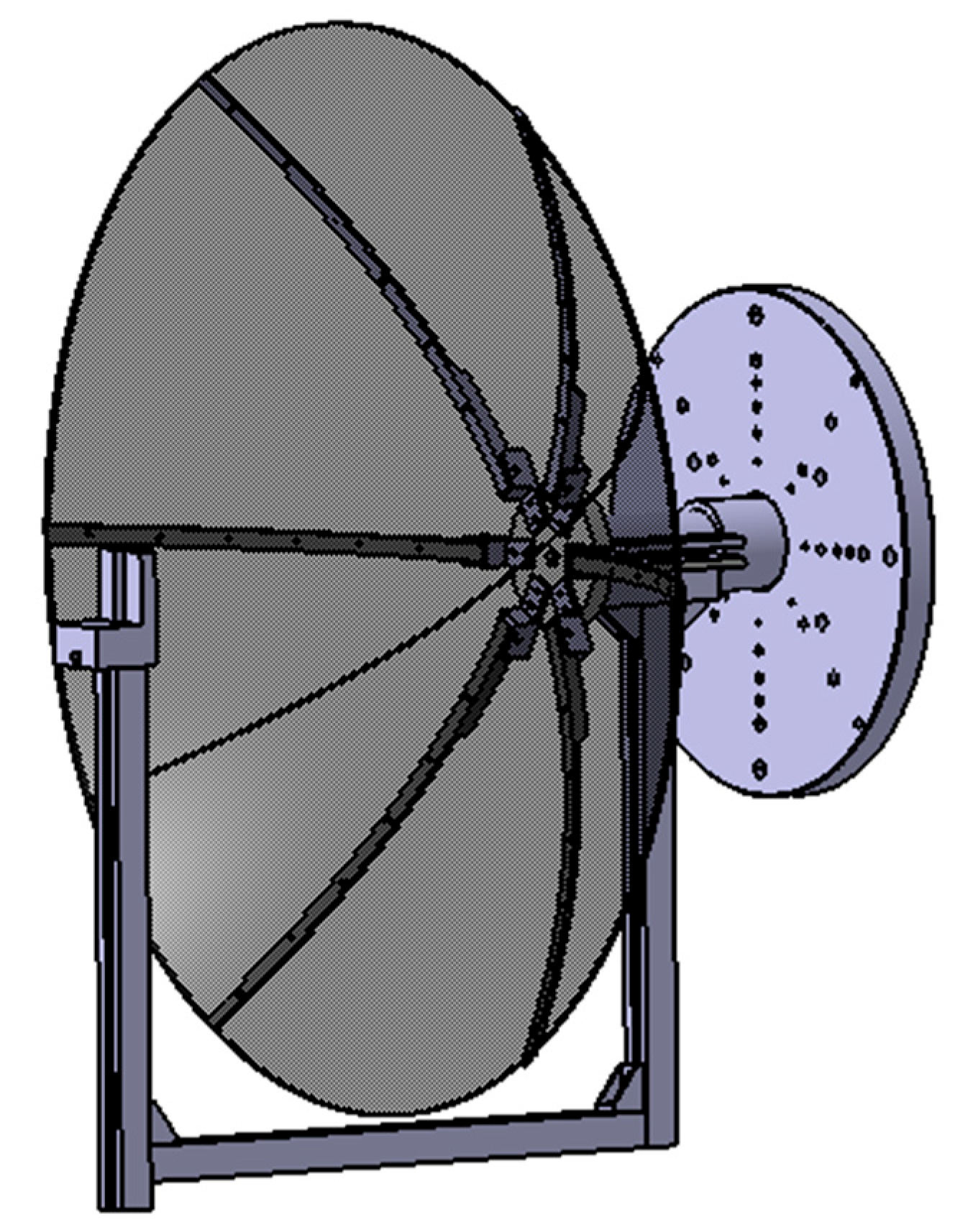
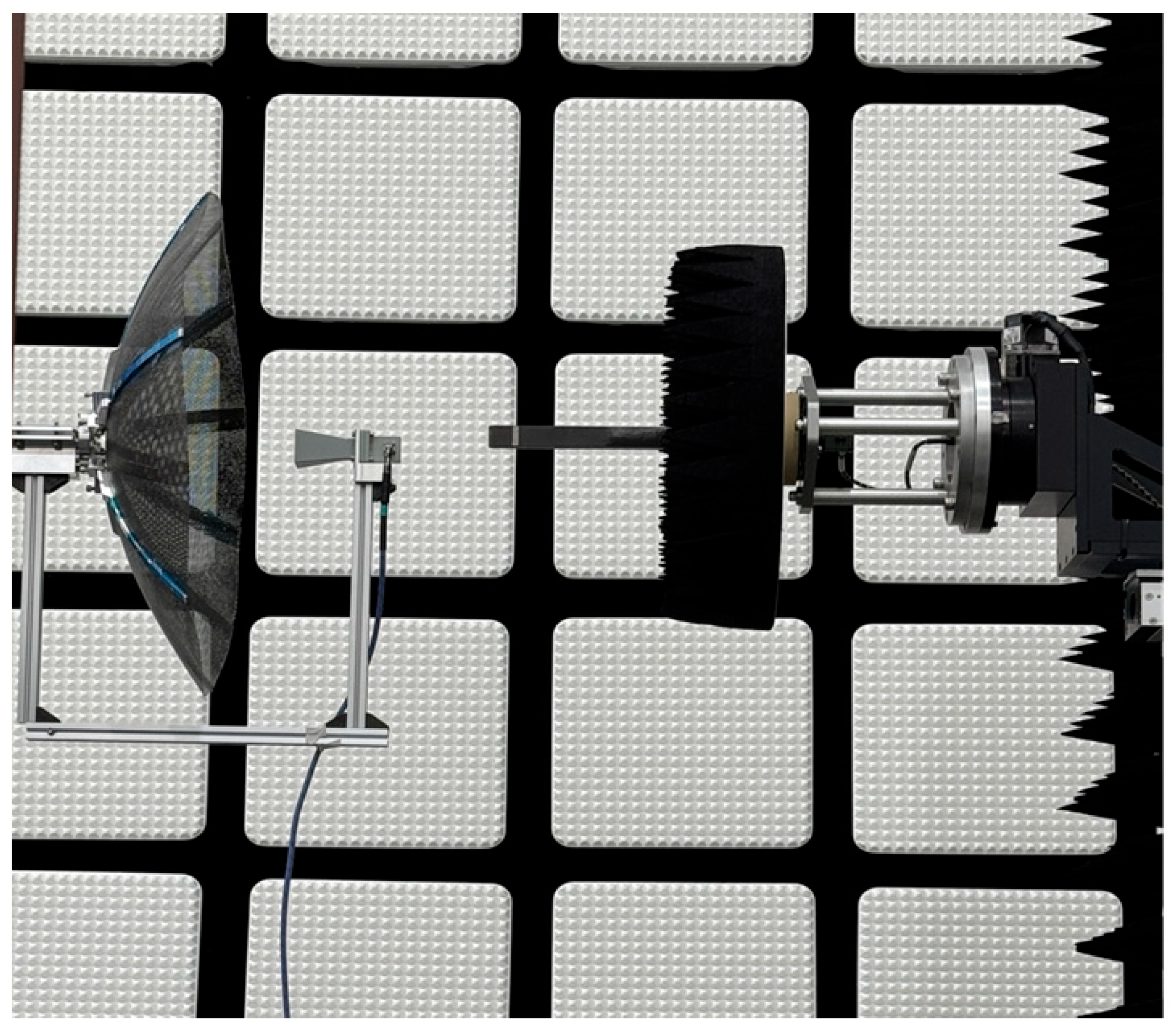
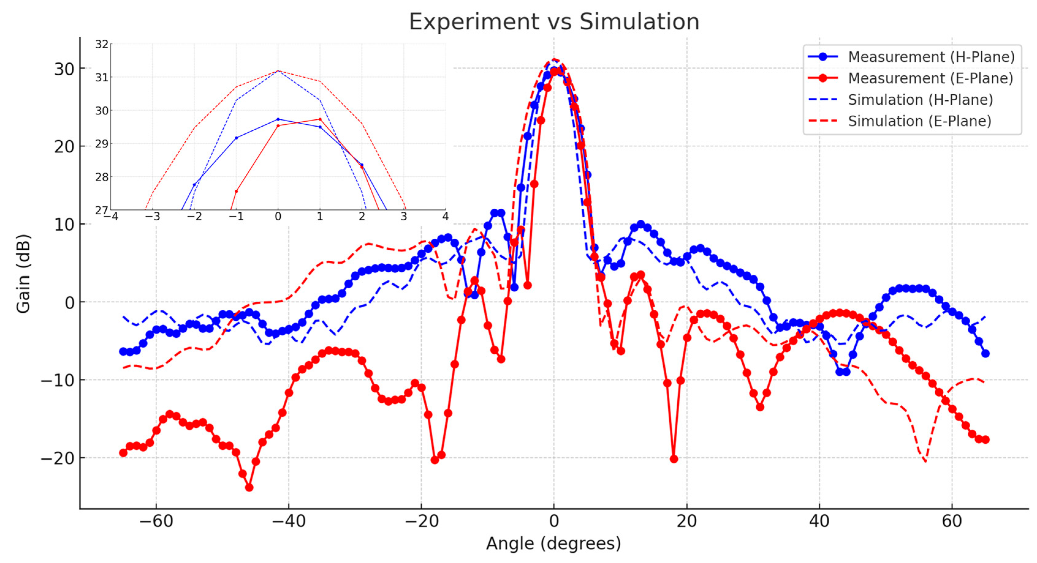
3. Performance of Reflector Antenna

A reflector antenna with a radius of 0.6 m has been fabricated, designed to optimize both mechanical characteristics and electrical performance. The antenna features a focal length-to-diameter ratio (F/D) of 0.33. Figure 9 presents the designed reflector model for near-field testing. The surface accuracy of the manufactured reflector is measured using the ARAMIS system, which employs digital image correlation (DIC) techniques to verify whether the fabricated panels conform precisely to the intended design (Figure 10). This method uses correlation-based matching algorithms to generate a three-dimensional surface profile. The calibration process requires a light source and a calibration panel, the size of which is determined by the dimensions of the object to be measured. The procedure is conducted in the following sequence: first, the distance between the camera and the calibration panel is adjusted; second, the camera focus is fine-tuned, followed by aperture adjustment; and finally, three-dimensional calibration is performed by varying the position and orientation of the calibration panel. Measurement errors are closely related to the quality of the calibration, which can be affected by inadequate lighting conditions and improper positioning or orientation of the calibration panel during the 3D calibration process. Figure 11 illustrates the surface error due to gravitational effects relative to the ideal parabolic shape. The measured surface accuracy is 0.17 mm RMS (λ/180 at 10 GHz), with most deviations attributed to minor fabrication inconsistencies. As anticipated, the reflector exhibits high geometric stability under gravitational loading. The reflector fabricated using the TWFS successfully maintains its parabolic shape without requiring additional complex support systems, validating its expected mechanical properties. Figure 12 displays the fabricated reflector antenna mounted on a near-field measurement setup for performance evaluation. The assembly is completed by positioning a WR-90 standard-gain horn antenna with a 10 dBi gain at the reflector’s focal point, while a WR-90 open-ended waveguide is used as the detector for the near-field measurements. The measurements are performed over a 65 cm × 65 cm planar area, positioned 10 cm away from the feed antenna. The measured performance of the fabricated reflector antenna is compared with the simulated predictions from CST Studio Suite 2024 (Dassault Systems, Vélizy-Villacoublay, France) (Figure 13). The maximum gain is recorded at approximately 30 dBi, closely aligning with the simulated value of 31.2 dBi. The 3 dBi beamwidth was measured as 5° in the H-plane and 4° in the E-plane, while the simulated values are 4° in the H-plane and 6° in the E-plane, demonstrating good agreement. The experimental gain drops observed at approximately ±19° are consistent with the theoretically expected antenna radiation pattern, which typically exhibits nulls due to the sinc function characteristics of an idealized reflector antenna. These nulls arise naturally at predictable angles as a fundamental consequence of diffraction from the finite antenna aperture, rather than from structural imperfections or measurement errors. Minor discrepancies between the measured and simulated null positions or depths may be attributed to slight deviations in the deployed antenna surface or minor asymmetries. Nevertheless, the primary cause of the gain drops at ±19° is a natural and theoretically predictable phenomenon, not an anomaly or defect. The measurement results likely include minor scattering effects caused by the feed horn and the aluminum profile securing it, as well as potential deviations in the feed horn’s orientation due to the profile’s weight. However, despite these sources of error, the measured performance of the reflector antenna closely matches the simulated predictions, confirming that the TWFS composite functions effectively as a reflector.

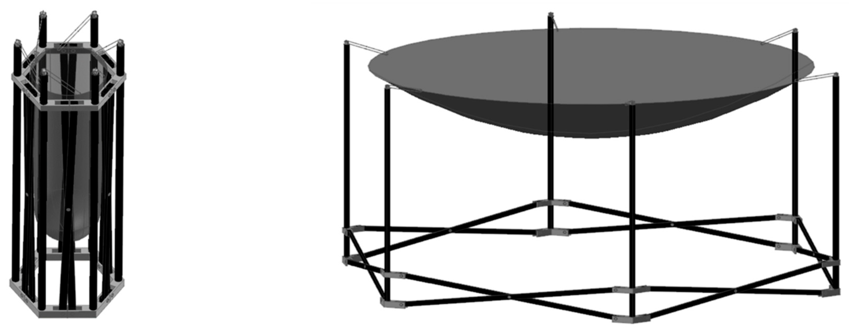
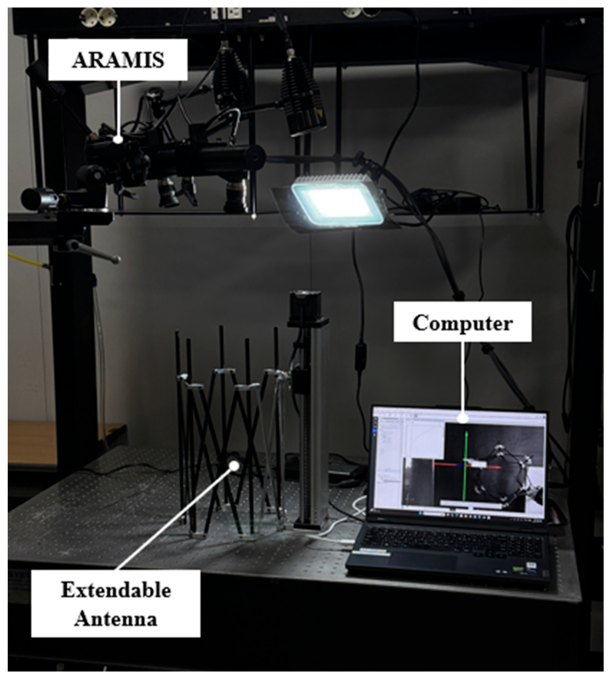
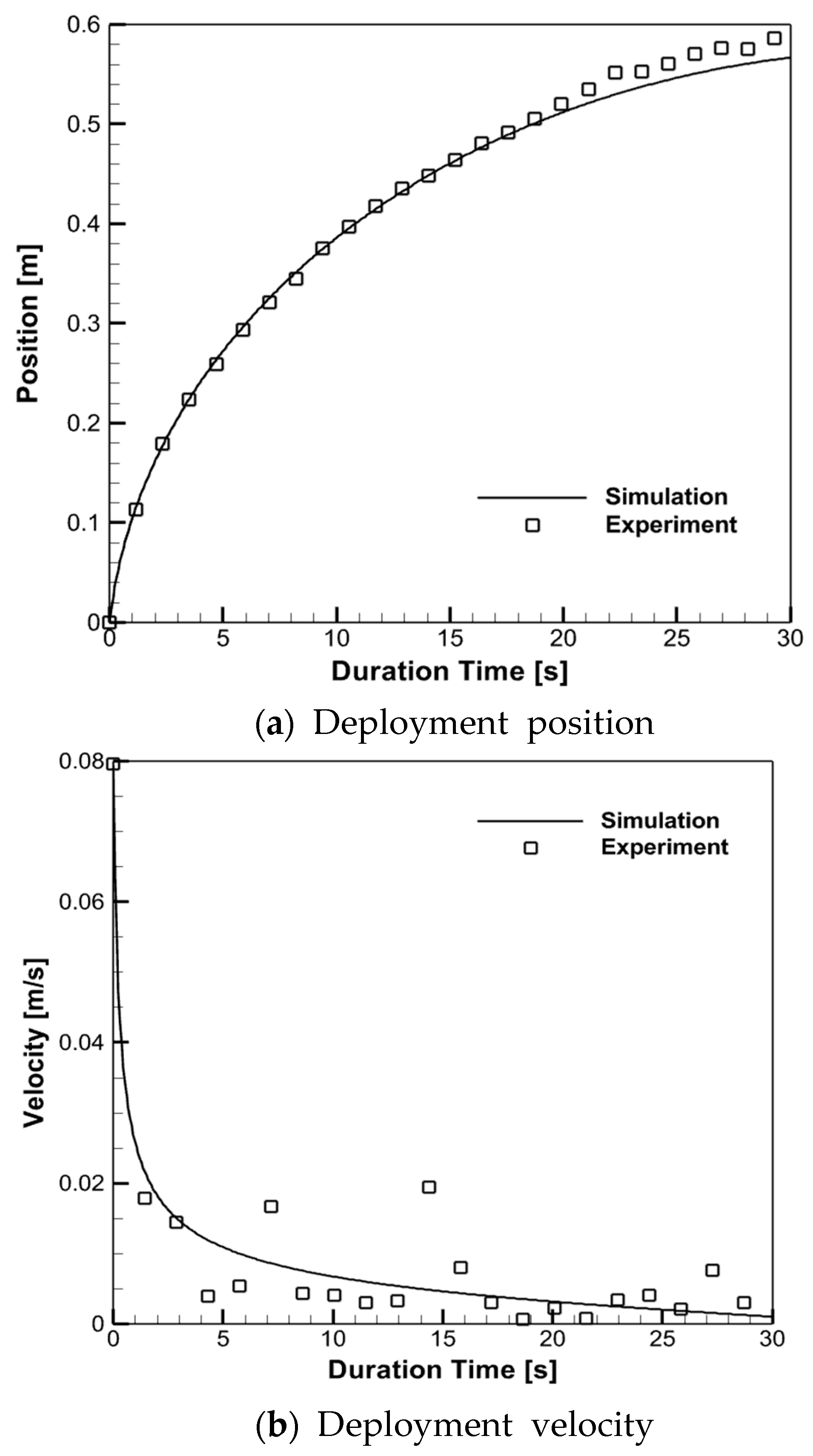
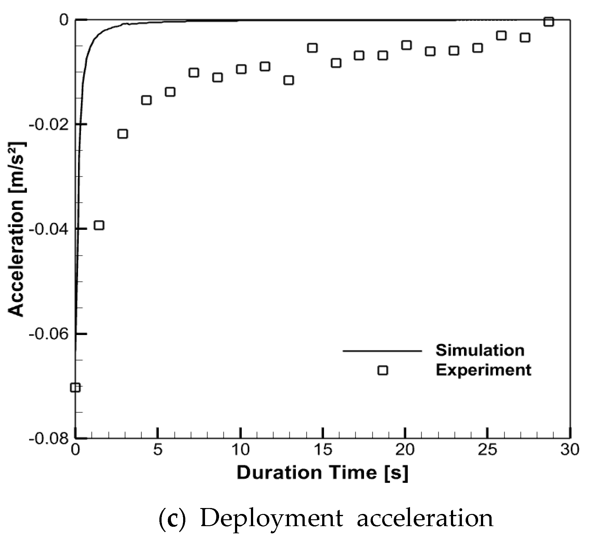
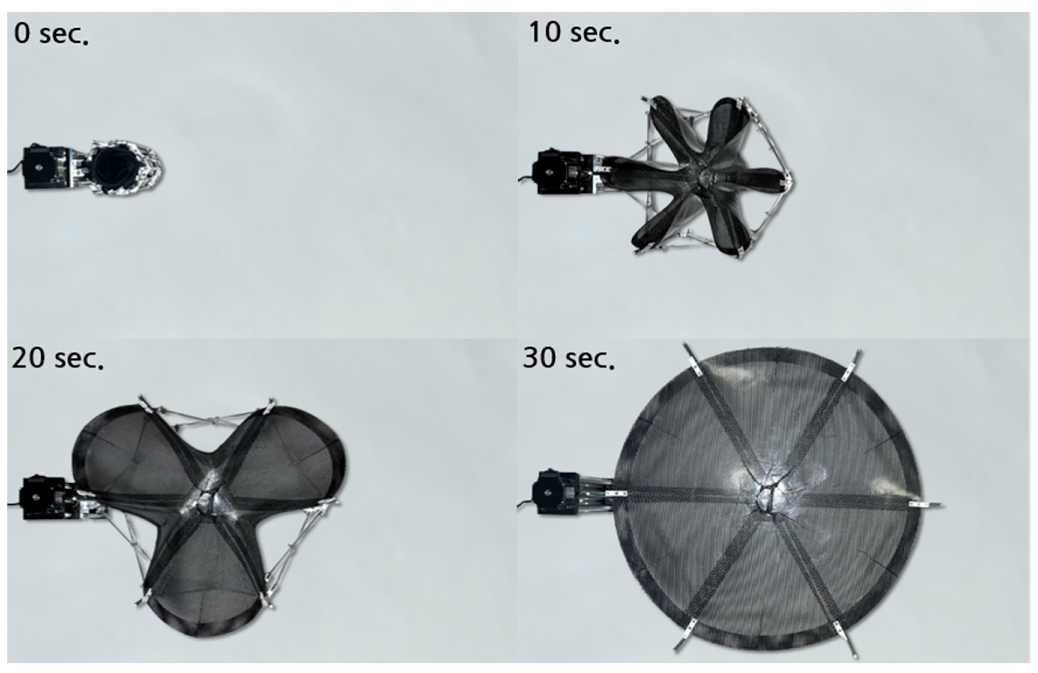
4. Deployment Mechanism

The deployment mechanism is designed to enable the flexible surface reflector to fold and unfold seamlessly without mechanical interferences. As illustrated in Figure 14, the conceptual deployment mechanism employs a six-unit extendable truss structure. This deployment mechanism is based on the polygonal pantograph [20] and is one of the primary mechanisms used for large space reflector antennas. The reflector is attached to the truss assembly without relying on tensioned support strings, requiring it to autonomously restore its designed parabolic shape through its inherent material elasticity. The deployment sequence of the extendable truss is depicted in Figure 15. The six-unit cells are synchronized with a single degree of freedom in vertical displacement during the unfolding process, ensuring a controlled and coordinated deployment. The deployment characteristics are experimentally evaluated under terrestrial gravity conditions. To precisely assess the kinematics behavior, the ARAMIS Digital Image Correlation (DIC) system is employed, enabling high-resolution and displacement measurements (Figure 16). Furthermore, a multibody dynamic analysis of the extendable truss structure is conducted using RecurDyn commercial software(V.9R5) to simulate the deployment process. Figure 17 presents a comparative analysis of deployment characteristics obtained from both experimental and numerical simulations. The unfolding process is designed to be completed within 30 s, and the variations in velocity and acceleration over time are illustrated. The acceleration asymptotically approaches zero due to position-controlled deployment facilitated by a linear motor. Minor discrepancies between the simulation and experimental results are attributed to frictional effects between components and ground contact. Nevertheless, a strong correlation between the experimental and numerical results is observed, validating the deployment dynamics of the proposed mechanism. Figure 18 illustrates the deployment procedure of the flexible surface reflector utilizing the extendable truss mechanism, demonstrating its sequential unfolding and structural recovery process.

5. Conclusions

A novel concept for a flexible surface reflector antenna has been demonstrated, highlighting its feasibility for spaceborne applications. The reflector utilizes a doubly curved flexible surface fabricated from a triaxially woven fabric-reinforced silicone (TWFS) composite. Unlike conventional membrane materials, TWFS composites do not require pretension when deployed as double-curved shell components, making them highly suitable for advanced deployable space structures. Experimental tensile tests on finite-size TWFS single-ply specimens reveal an anisotropic mechanical response, despite the quasi-isotropic nature of the fabric’s weave pattern. This anisotropic behavior must be carefully considered in the design and structural optimization of the reflector surface to ensure deployment reliability and accurate surface conformance. Furthermore, the RF performance of the reflector has been tested and validated. Surface coating techniques aimed at enhancing the RF properties of TWFS composites are under investigation to enable high-frequency operational capabilities. The extendable truss deployment mechanism has been successfully demonstrated, accommodating a 0.6 m diameter parabolic reflector within a compact stowed volume, thereby optimizing space efficiency for satellite integration. The proposed design presents a structurally efficient and scalable solution for deployable reflector antennas in small satellite platforms, offering a pathway toward high-performance spaceborne communication systems.

Author Contributions

Conceptualization, H.-Y.J., D.-S.K. (Deok-Soo Kang) and J.-H.Y.; Methodology, D.-S.K. (Dong-Seok Kang) and K.P.; Validation, D.-H.K., J.-H.C. and M.-H.L.; Supervision, J.-H.R. and J.-W.L. All authors have read and agreed to the published version of the manuscript.

Funding

This research received no external funding.

Data Availability Statement

The data presented in this study are available on request from the corresponding author. The data are not publicly available due to privacy.

Acknowledgments

This research is performed based on the cooperation with Korea Aerospace University—LIG Nex1 Cooperation.

Conflicts of Interest

Authors Dong-Seok Kang, Hwa-Young Jung, Deok-Soo Kang, Ji-Hyeon Yun were employed by the company LIG Nex1, and Jin-Ho Roh was employed by the company HSCUBE Inc. The remaining authors declare that the research was conducted in the absence of any commercial or financial relationships that could be construed as a potential conflict of interest.

References

  1. Rahmat-Samii, Y.; Manohar, V.; Kovitz, J.M. For Satellites, Think Small, Dream Big: A Review of Recent Antenna Developments for CubeSats. IEEE Antennas Propag. Mag. 2017, 59, 22–30. [Google Scholar] [CrossRef]
  2. Hedgepeth, J.M. Accuracy Potentials for Large Space Antenna Reflectors with Passive Structure. J. Spacecr. Rocket. 1982, 19, 211–217. [Google Scholar] [CrossRef]
  3. Peral, E.; Tanelli, S.; Statham, S.; Joshi, S.; Imken, T.; Price, D.; Sauder, J.; Chahat, N.; Williams, A. RainCube: The First Ever Radar Measurements from a CubeSat in Space. J. Appl. Remote Sens. 2019, 13, 032504. [Google Scholar] [CrossRef]
  4. Murphey, T.W.; William, F.; Bruce, D.; Juan, M. High Strain Composites. In Proceedings of the 2nd AIAA Spacecraft Structures Conference, Kissimmee, FL, USA, 5–9 January 2015. [Google Scholar]
  5. Datashvili, L.; Maghaldadze, N.; Baier, H.; Friemel, M.; Schmidt, L.D.R.; Luo, T. Enabling Technologies and Architectures at LSS GmbH for European Large Deployable and Reconfigurable Reflector Antennas. In Proceedings of the Deutscher Luft- Und Raumfahrtkongress, Munich, Germany, 23–25 September 2017. [Google Scholar]
  6. Datashvili, L. Multifunctional and Dimensionally Stable Flexible Fibre Composites for Space Applications. Acta Astronaut. 2010, 66, 1081–1086. [Google Scholar] [CrossRef]
  7. Tan, L.T.; Pellegrino, S. Ultra Thin Deployable Reflector Antennas. In Proceedings of the 45th AIAA/ASME/ASCE/AHS/ASC Structures, Structural Dynamics & Materials Conference, Palm Springs, CA, USA, 19–22 April 2004. [Google Scholar]
  8. Dufour, L.; Datashvii, L.; Guinot, F.; Legay, H.; Goussetis, G. Origami Deployable Reflector Antenna for CubeSats. In Proceedings of the AIAA SciTech 2021 Forum, Virtual Event, 11–15 & 19–21 January 2021. [Google Scholar]
  9. Datashvili, L.; Baier, H.; da Rocha-Schmidt, L. Multi-scale Analysis of Structures Made of Triaxially Woven Fabric Composites with Stiff and Flexible Matrix Materials. In Proceedings of the 52nd AIAA/ASME/ASCE/AHS/ASC Structures, Structural Dynamics and Materials Conference, Denver, CO, USA, 4–7 April 2011. [Google Scholar]
  10. Kueh, A.; Pellegrino, S. Thermo-elastic behavior of single ply triaxial woven fabric composites. In Proceedings of the 47th AIAA/ASME/ASCE/AHS/ASC Structures, Structural Dynamics, and Materials Conference, Newport, RI, USA, 1–4 May 2006. [Google Scholar]
  11. Kueh, A.; Soykasap, O.; Pellegrino, S. Thermo-Mechanical Behavior of Single-Ply Triaxial Weave Carbon Fiber Reinforced Plastic. In Proceedings of the European Conference on Spacecraft Structures, Materials and Mechanical Testing 2005 (ESA SP-581), Noordwijk, The Netherlands, 10–12 May 2005. [Google Scholar]
  12. ASTM D638; Standard test method for tensile properties of plastics. ASTM International: West Conshohocken, PA, USA, 2014.
  13. Aramis 3D Strain Measurement System. Available online: https://www.zeiss.com/metrology/en/home.html (accessed on 4 May 2025).
  14. Kueh, A.; Pellegrino, S. Triaxial Weave Fabric Composites, CUED/D-STRUCT/TR223. In European Space Agency Contractor Report; University of Cambridge: Cambridge, UK, 2007. [Google Scholar]
  15. Gao, J.; Chen, W.; Yu, B.; Fan, P.; Zhao, B.; Hu, J.; Zhang, D.; Fang, G.; Peng, F. A multi-scale method for predicting ABD stiffness matrix of single-ply weave-reinforced composite. Compos. Struct. 2019, 230, 111478. [Google Scholar] [CrossRef]
  16. Tian, W.; Qi, L.; Chao, X.; Liang, J.; Fu, M. Periodic boundary condition and its numerical implementation algorithm for the evaluation of effective mechanical properties of the composites with complicated micro-structures. Compos. Part B Eng. 2019, 162, 1–10. [Google Scholar] [CrossRef]
  17. Cheng, Q. Fiber-Reinforced Composites; Nova Science Publishers, Inc.: Hauppauge, NY, USA, 2011; pp. 612–615. [Google Scholar]
  18. Kueh, A. Size-influenced mechanical isotropy of singly-plied triaxially woven fabric composites. Compos. Part A Appl. Sci. Manuf. 2014, 57, 76–87. [Google Scholar] [CrossRef]
  19. Yoon, S.S.; Lee, J.W.; Lee, T.-K.; Roh, J.H. Insensitivity Characteristics in the Dual Polarization of Deployable CFRP Reflector Antennas for SAR. IEEE Trans. Antennas Propag. 2018, 66, 88–95. [Google Scholar] [CrossRef]
  20. Cherniavsky, A.G.; Gulyayev, V.I.; Gaidaichuk, V.V.; Fedoseev, A.I. Large Deployable Space Antennas Based on Usage of Polygonal Pantograph. J. Aerosp. Eng. 2005, 18, 139–145. [Google Scholar] [CrossRef]
Figure 1. Fabricated TWFS Composite.
Aerospace 12 00414 g001
Figure 2. Experimental Setup for Tensile Test.
Aerospace 12 00414 g002
Figure 3. Numerical Model of TWFS.
Aerospace 12 00414 g003
Figure 4. Stress–strain Curves with Fabric Direction.
Aerospace 12 00414 g004
Figure 5. Tensile Test Results with Aspect Ratio.
Aerospace 12 00414 g005
Figure 6. Deformed Shape of the Specimen in 90° direction.
Aerospace 12 00414 g006
Figure 7. Test Setup for Waveguide Measurements.
Aerospace 12 00414 g007
Figure 8. Reflection Coefficient and Equivalent Electrical Conductivity.
Aerospace 12 00414 g008
Figure 9. Test Model of Reflector Antenna.
Aerospace 12 00414 g009
Figure 10. Surface Error Measurement.
Aerospace 12 00414 g010
Figure 11. Experimental Measurement of Surface Error.
Aerospace 12 00414 g011
Figure 12. Reflector Antenna in Near-field Test.
Aerospace 12 00414 g012
Figure 13. Comparisons of the Reflector Antenna Patterns.
Aerospace 12 00414 g013
Figure 14. Extendable Truss Deployment Mechanism.
Aerospace 12 00414 g014
Figure 15. Simulation of Deployment Procedure.
Aerospace 12 00414 g015
Figure 16. Experimental Setup for Deployment Characteristics.
Aerospace 12 00414 g016
Figure 17. Comparisons of Deployment Characteristics.
Aerospace 12 00414 g017aAerospace 12 00414 g017b
Figure 18. Deployment Procedure of the Reflector.
Aerospace 12 00414 g018
Table 1. Mechanical properties of the tow.
PropertyValue
E 1 97.79 GPa
E 2 = E 3 6.34 GPa
G 12 = G 13 1.64 MPa
G 23 2.27 MPa
ν 12 = ν 13 0.37
ν 23 0.40
Disclaimer/Publisher’s Note: The statements, opinions and data contained in all publications are solely those of the individual author(s) and contributor(s) and not of MDPI and/or the editor(s). MDPI and/or the editor(s) disclaim responsibility for any injury to people or property resulting from any ideas, methods, instructions or products referred to in the content.

