Abstract
This paper presents an offline optimal trajectory planning method for powered parachutes (PPCs) using dynamic model simulations, emphasizing their potential in applications such as remote sensing and aerial delivery systems. A six-degrees-of-freedom (6-DOF) dynamic model of the PPC is developed, complemented by a novel optimization technique called Incremented Genetic Algorithms (IGA). IGA improve the computational efficiency by dynamically increasing the number of variables only when optimization goals are unmet, eliminating the need to predefine input variable counts. This approach significantly reduces the computational time and CPU usage while maintaining cost-effectiveness for 3D trajectory planning. The proposed method was validated on three trajectories under diverse constraints, including the time, position, and predefined obstacles. The results demonstrate that IGA can effectively generate optimal trajectories using a single control parameter (the parachute steering angle) and a minimal number of control points, showcasing its practicality and efficiency.
1. Introduction
Powered parachutes (PPCs) have evolved into indispensable and versatile aerial platforms, adept for a wide range of applications including aerial photography, agricultural spraying, and the burgeoning sector of autonomous aerial cargo delivery. Classified as an ultralight aircraft, PPCs use a ram-air parachute for lift and a rear-mounted propeller for propulsion. Their simple design, low operating speed, and significant lifting capacity make them ideal for low-altitude missions.
The advent of autonomous powered parachutes marks a pivotal advancement in aerial delivery systems, primarily due to their ability to operate without human intervention []. These systems are meticulously engineered to autonomously transport payloads, providing a significant advantage in challenging environments such as disaster zones, remote locations, and rugged terrain. The design of autonomous PPCs features a flexible parachute canopy, a robust cargo undercarriage, and advanced navigation systems that facilitate independent operation. Their ability to access otherwise inaccessible areas, combined with their cost-effectiveness, positions them as a viable alternative to traditional fixed-wing or rotorcraft delivery systems.
The aerodynamic stability of PPCs is derived from their pendulum-like structure, with the payload acting as a stabilizing mass beneath the parachute. Despite this inherent stability, challenges arise due to the sensitivity of the flexible canopy to aerodynamic forces, which can lead to instability in turbulent conditions or during complex maneuvers. Furthermore, enhancing delivery efficiency—considering factors such as timing, precise positioning, and obstacle avoidance—necessitates sophisticated control and trajectory optimization techniques.
Controlling an autonomous PPC involves managing thrust, steering, and stability to ensure accurate and reliable operation. Directional control is achieved by manipulating the suspension lines to tilt the parachute canopy, enabling turns and course corrections. Thrust, generated by the rear-mounted propeller, regulates the speed and altitude. Stability control algorithms are essential to dampen oscillations and maintain smooth flight, especially in dynamic or unpredictable conditions. In addition, real-time navigation systems equipped with sensors and GPS ensure that the PPC can follow predefined trajectories while responding to environmental changes and avoiding obstacles.
Despite these capabilities, optimizing the 3D trajectory of PPCs for aerial delivery remains a complex problem. Traditional trajectory planning methods may struggle to balance computational efficiency with the high-dimensional and nonlinear nature of the PPC’s dynamics. This study addresses these challenges by employing the IGA, which incrementally refines the trajectory using a simplified problem structure. Unlike conventional GAs, the IGA start with a limited number of control points and gradually increases their resolution, enabling efficient and accurate trajectory optimization [,,]. However, optimizing the 3D trajectory of PPCs for cargo delivery poses significant challenges, especially when considering time and position constraints, or obstacle avoidance in dynamic environments [].
Unlike a conventional aircraft, PPCs lack traditional control surfaces and instead rely on the manipulation of parachute control lines and engine power to achieve lateral and longitudinal control [,,,,]. This makes them more susceptible to environmental disturbances, such as wind gusts, which can complicate trajectory planning. In this context, the primary objective is to generate a flight path that ensures safe and efficient delivery while satisfying predefined constraints, such as obstacle avoidance [] and maintaining a time-efficient trajectory. Traditional control methods, such as Proportional–Integral–Derivative (PID) controllers [,,,] and Model Predictive Control (MPC) have been widely used in PPC systems, but their ability to handle the complex and dynamic challenges of 3D trajectory optimization is limited [,].
PID controllers, while reliable and widely used in control systems, are primarily designed for applications with linear or near-linear dynamics. For powered parachute (PPC) systems, which exhibit significant nonlinear behavior due to aerodynamic forces, under actuation, and environmental disturbances, PID-based methods may not provide the necessary accuracy or adaptability for real-time trajectory correction [,]. Their inability to anticipate the system behavior or account for future states further limits their utility in complex flight scenarios.
Similarly, Model Predictive Control (MPC) offers notable advantages by using a model of the system to predict future states and optimize control inputs over a finite prediction horizon []. MPC is particularly effective in managing multi-variable systems and enforcing input and state constraints. However, its reliance on online optimization at each control step introduces substantial computational demands. This becomes especially problematic in PPC applications that involve dynamic environments, real-time obstacle avoidance, or rapidly changing weather conditions. In such cases, the computational overhead can lead to delays or suboptimal responses, undermining the controller’s ability to react promptly to external disturbances or changes in mission objectives. These constraints reduce the practical applicability of MPC in real-time aerial delivery operations using PPCs, where control strategies must be both responsive and computationally efficient.
Recent studies emphasize the role of advanced artificial intelligence-based autonomy in improving situational awareness and reducing the operator cognitive workload. However, they also highlight the necessity of incorporating frameworks that focus on human-centered considerations, such as systems designed to analyze human factors and structured decision-making processes that include observation, orientation, decision, and action. These approaches aim to mitigate over-reliance on automation and are particularly relevant for powered parachute systems, which require a careful balance between automated optimization and human decision making, especially in dynamic and unpredictable environments []
In addition to traditional control strategies, the literature includes multi-criteria decision-making methods—such as hierarchical processes for analyzing priorities, fuzzy logic approaches for managing uncertainty, and techniques for ranking options based on similarity to ideal solutions. These methods highlight the importance of the communication efficiency and operator performance in trajectory planning [].
Recent advances in the parachute system design provide valuable insights applicable to PPC trajectory optimization. A low-cost parachute landing system for fixed-wing UAVs has been designed, emphasizing the importance of lightweight materials and rapid deployment mechanisms [,]. These findings suggest that enhanced parachute designs could improve PPC deployment systems, particularly in resource-constrained settings. Similarly, the development of a swept-back parachute with superior stability and maneuverability during descent underscores the role of aerodynamic optimizations in improving flight path accuracy []. Additionally, a 12-DoF parachute–riser–payload model using Kane’s method has been introduced, demonstrating computationally efficient approaches for simulating dynamic parachute behavior []. These innovations provide a foundation for addressing the challenges of PPC trajectory planning.
Other researchers have attempted to maximize the parachute trajectory using an adaptive mesh refinement method combined with local direct collocation techniques. While this combination can improve the accuracy, it also increases computational complexity and hampers parallelization, as certain regions of the mesh require more intensive computation due to refinement and collocation [].
Furthermore, a parafoil path planning method based on natural principles has been proposed. This approach represents possible routes as tree structures, where each branch corresponds to a path from the starting point to every reachable destination. The branches are then ranked to identify the optimal trajectory. However, this method is computationally intensive, particularly when applied to complex systems or over extended time periods [].
To overcome these challenges, this paper proposes the use of IGA for optimizing 3D trajectories of PPCs. GAs have been widely recognized for their ability to handle non-linear optimization problems by mimicking the process of natural selection []. However, traditional GAs may struggle with high-dimensional solution spaces, especially when a large number of optimization variables are involved. The proposed IGA address this issue by starting with a simplified problem structure, where only a limited number of control points define the trajectory. As the optimization progresses, the algorithm incrementally adds control points, refining the trajectory to better satisfy the required constraints, such as the time efficiency, obstacle avoidance, and delivery accuracy.
The Incremental GA-based approach offers several advantages over traditional GAs. First, by starting with a reduced set of optimization variables, the IGA improve the computational efficiency, allowing for faster convergence to an optimal solution. This is particularly important in aerial delivery applications, where time-sensitive decisions must be made in a dynamic environment. Furthermore, the piecewise linear representation of the trajectory provides flexibility in adjusting the path during optimization, allowing the system to more efficiently explore the solution space and adapt to complex constraints. As the optimization progresses, the number of control points is increased only when necessary, ensuring the efficient use of computational resources while preserving high trajectory accuracy.
The validation of PPC control strategies, including trajectory optimization, is typically performed through numerical simulations. Simulations allow researchers to evaluate the performance of control algorithms under different flight conditions and dynamic scenarios. Previous work in this field has focused on developing control models based on linearized dynamics at specific operating points [,,]. However, these methods often fail to capture the full complexity of PPC behavior. By integrating findings from recent parachute design studies, the proposed approach leverages the computational efficiency and physical insights to enhance trajectory planning.
The use of IGA in PPC trajectory optimization represents a novel contribution to the field. It enables the design of more efficient flight paths that meet strict operational requirements. By addressing the shortcomings of traditional control methods, this work paves the way for future advancements in PPC-based aerial delivery systems, emphasizing safety, efficiency, and reliability. The results have broad applicability, including military logistics, humanitarian aid delivery, and autonomous cargo transport in remote areas [].
This paper is organized as follows: Section 1 provides an introduction and comprehensive literature review, highlighting existing approaches and identifying research gaps. Section 2 focuses on the development of the mathematical model for the PPC flying vehicle, which serves as the basis for trajectory optimization. Section 3 introduces the proposed IGA optimization technique with a detailed explanation of its methodology and implementation. Section 4 showcases the results of applying the IGA to generate optimal trajectories under various constraints, with the system performance evaluated through simulations. This paper concludes with a discussion of key findings and recommendations for future research directions.
2. Powered Parachute Model
The PPC, as shown in Figure 1, can be modeled as a dynamic system with either six or nine degrees of freedom (DOF), depending on the desired level of accuracy and computational efficiency. The 6DOF model captures the translational and rotational motions of the PPC as a rigid body, making it suitable for most trajectory optimization and control design applications. In contrast, the 9DOF model incorporates additional degrees of freedom to account for the flexibility of the parachute canopy, offering higher fidelity at the cost of increased computational complexity [,,,,]. The 8-DOF dynamic model was used in []. A key aspect of this research is the introduction of differential control, which is shown to increase the yaw motion response speed, but with the cost of using two motors.
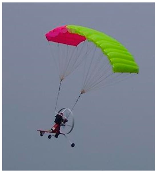
Figure 1.
Powered parachute flying vehicle.
For this study, the 6DOF model is selected, as it provides a precise balance between accuracy and efficiency. This model uses a set of coupled, nonlinear equations based on Newtonian mechanics to describe the PPC’s motion, including the interactions between aerodynamic forces, propeller thrust, and gravitational effects. These equations are parameterized using coefficients derived from experimental and computational studies in the literature [,,,,].
In this six-degrees-of-freedom (6DOF) model, any relative motion that might happen between the parafoil and the fuselage during flight is disregarded, treating both parts as a unified rigid body, as shown in Figure 2 [,,,].
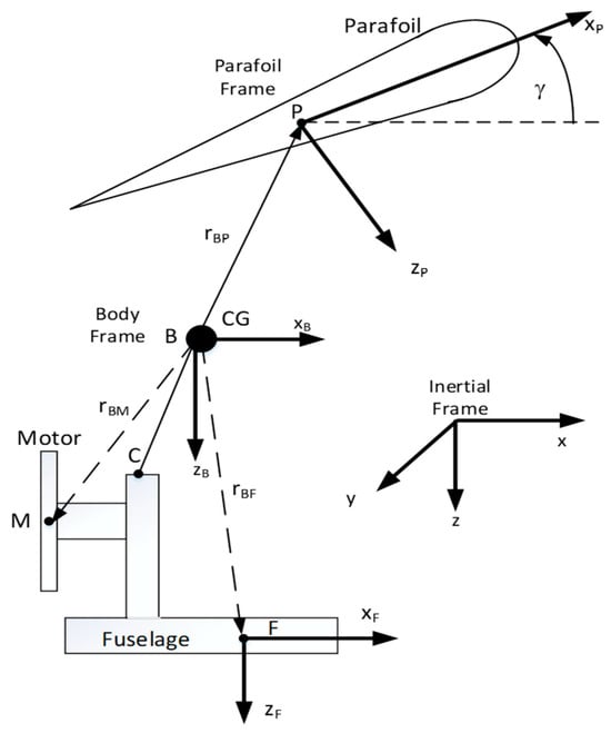
Figure 2.
PPC coordinate system.
The mathematical model for the PPC uses four reference frames: the Earth frame, the body frame, the fuselage frame, and the parafoil frame. Using the superscript T to represent vector transposition, the vector indicates the position of the PPC’s center of gravity (CG) regarding the Earth frame . The speed of the PPC’s center of gravity in relation to the body frame is given as . The angular position of the body frame in relation to the Earth frame is indicated by the vector , which relates to the roll, pitch, and yaw angles. The vector of the angular velocity of the PPC in the body frame can be expressed in terms of η as follows []
where C and S represent the abbreviations for cosine and sine, respectively. The transformation matrix accounts for the coupling effects between the angular velocity components, particularly during maneuvers involving dynamic changes in pitch or roll. This relationship is critical for capturing the PPC’s rotational dynamics in a global frame of reference.
The variation in the inertial position over time can be stated as:
This equation describes the translational motion of the PPC’s center of gravity relative to the Earth frame. Here, represents the velocity in the Earth frame. The rotation matrix transforms the body frame velocities into the Earth frame. This transformation is crucial for accurately predicting the PPC’s trajectory in global coordinates, enabling precise navigation and effective obstacle avoidance, particularly during complex flight maneuvers. The rotation matrix can be specified as:
The equations describing translational motion in the body frame can be written as:
where m denotes the overall mass of the PPC vehicle and g stands for the gravitational constant. This equation governs the translational motion of the PPC in the body frame. The terms Ff, FM, and FP represent the forces generated by the fuselage, motor, and parafoil, respectively. The term mg denotes the gravitational force acting on the PPC and is the acceleration in the body frame. This equation balances the forces acting on the PPC, ensuring translational stability and accuracy in trajectory control.
The equations describing rotational motion in the body frame can be written as:
This equation describes the rotational dynamics of the PPC. The inertia matrix IB quantifies the resistance to rotational motion, while Mf and Mδa denote the moments generated by the fuselage, motor, and parafoil, respectively. The term δa represents the moment induced by the parafoil’s steering angle. This equation captures the rotational responses necessary to maintain the PPC’s desired orientation and heading during flight. Comprehensive information about the full dynamics of the PPC is available in [].
The inertia and aerodynamic properties of the PPC model utilized in the simulation are detailed in Table 1 for mass and geometric properties, and Table 2 shows the parafoil aerodynamic coefficients [].

Table 1.
PPC mass and geometric properties.

Table 2.
Parafoil Aerodynamics Properties.
These equations provide the foundational mathematical models that govern the dynamics of the PPC. They allow for the accurate prediction of the PPC’s position, orientation, and forces during flight. The next step involves using these models in conjunction with the Incremental Genetic Algorithm (IGA) to optimize the trajectory of the PPC under various constraints, such as obstacle avoidance and time efficiency.
3. Optimization
To determine the optimal trajectory, an “optimization via simulation” approach is utilized. This method focuses on identifying the optimal input parameters that allow the PPC simulator to meet the desired trajectory and constraints. The process involves running multiple simulations of the PPC model, with the number of iterations controlled by the chosen optimization technique.
The process starts by defining the desired trajectory, which encompasses details such as the destination, waypoints, time constraints, and any obstacles that need to be avoided. Additionally, the dynamic model of the PPC is established to ensure an accurate simulation of the vehicle’s behavior. To refine the control inputs, a modified version of the GA, referred to as the IGA is utilized.
The IGA incorporates the same fundamental components as traditional GA, including selection, crossover, and mutation. It begins by addressing smaller GA problems with fewer variables and gradually increases the number of variables to achieve the desired accuracy. As the problem size grows, the IGA utilizes the solution from the smaller problem as an initial estimate for the larger problem. This process reduces the time and computational resources needed to solve the problem by about 40% [].
In the IGA process, random input parameters are generated and input into the PPC simulator. The resulting trajectory from the simulation is then compared with the desired trajectory, and the difference—known as the “error budget” is calculated. This error signifies the deviation between the simulated trajectory and the intended path. Subsequently, this error is incorporated into the cost function, directing the IGA to adjust the input parameters in future iterations to minimize the error.
This iterative optimization process continues, with each cycle of the IGA refining the input parameters to further reduce the error. Over successive generations, the system adapts and improves the input parameters, ultimately yielding an optimized trajectory that meets the specified requirements, such as the positional accuracy, obstacle avoidance, or timing constraints. Figure 3 illustrates the entire optimization loop, depicting the interaction between the IGA, the PPC simulator, and the cost function.
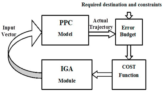
Figure 3.
Trajectory optimization process diagram.
The use of the IGA enables the efficient exploration of the input parameter space, ensuring that the PPC achieves the desired performance with minimal deviation. The adaptive nature of the IGA ensures that it converges to highly accurate trajectory solutions, making it a robust method for trajectory optimization. Future work could focus on incorporating more advanced optimization techniques or hybrid algorithms to further enhance the system’s efficiency and accuracy, particularly in more complex or dynamic environments, where real-time adjustments may be necessary.
GAs are stochastic global search techniques inspired by the principles of genetics. Essentially, a GA operates as outlined in Algorithm 1.
| Algorithm 1. The pseudo-code for GA |
| BEGIN GA Initialize the population randomly. WHILE (stopping condition not met) DO BEGIN Select parents from the current population. Generate offspring by crossing over the selected parents. Apply mutation to the offspring. Add the offspring to the population. Reduce the population size to maintain a consistent number. END Output the best individual discovered. END GA |
The IGA is an iterative extension of the traditional GA [] particularly suited for optimization problems where parameters change over time, such as direction commands for unmanned aerial vehicles (UAVs), robots, etc. Previously, such problems were addressed numerically by approximating the solution with higher-order polynomials or splines and then determining the coefficients that satisfied the optimization criteria.
In an IGA, a limited number of values are initially assigned to each design variable. For example, in the case of the path planning controller, a single control variable, the steering angle, is used. Its initial values are set randomly in the range [−1.5 rand, 1.5 rad]. Control points are uniformly distributed over time to shape the command function. Between these control points, the command variable is assumed to change linearly, using direct linear interpolation, as depicted in Figure 4.
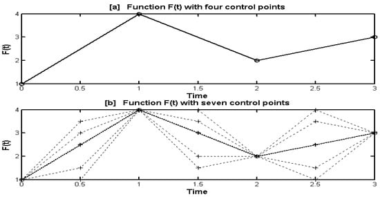
Figure 4.
Piecewise linear approximation using incrementing control points.
Figure 4a demonstrates how four control points can define the shape of the command variable, F(t), over time. The GA’s task is to identify the optimal values of these four points that minimize the objective function. If the GA cannot find an optimal solution within a given tolerance, the number of control points is increased, providing more flexibility in shaping the command variable.
Figure 4b illustrates F(t) after three additional control points are introduced, totaling seven control points. As shown by the dotted lines, this increased number of control points allows F(t) to represent more complex functions than in Figure 4a, where only four control points were used.
The incremental process is repeated until the desired accuracy is reached. During each iteration, the search space, which consists of the design variables, is expanded by adding more control points. These new control points are initialized through linear interpolation between the surrounding, previously established values. The process starts with a coarse grid of control points, and the solutions obtained from this grid serve as the initial population for a finer grid. This iterative refinement continues until a stopping condition is satisfied.
Employing linear interpolation streamlines the computation process and guarantees that the initial population in the expanded search space maintains the optimal fitness achieved in the earlier, less detailed search space. This method enables quicker convergence to an enhanced solution compared to a traditional GA [].
The steps involved in the IGA optimization procedure are outlined in Algorithm 2.
| Algorithm 2. The pseudo-code for IGA |
| Inputs: n: Initial number of control points for steering angle (number of optimization variables) m: Number of GA iterations StoppingCondition: Condition to terminate GA iterations (e.g., max iterations, fitness threshold) ProblemSizeIncreaseCondition: Condition to increase problem size (e.g., after a certain number of iterations if the required cost function value is not satisfied) Output: BestSteeringAngleEnsemble: Optimized steering angle ensemble (steering angle control points) Variables: Population: Array of steering angles ensembles (each steering angles ensemble has n random values of control points) Fitness: Array of fitness scores corresponding to each steering angle ensemble in Population Simulator: Function to simulate PPC flight CostFunction: Function to evaluate the cost of an ensemble based on simulation results 1. Initialize the number of control points for steering angle to n values 2. Initialize the Population with random steering angle ensembles (functions of time) based on n control points. 3. OuterLoop = True; 4. While OuterLoop: 5. For each steering angle ensemble in Population: 6. Run the Simulator with the steering angle ensemble as input. 7. Collect simulation data: Time, Position, Obstacle Crossing. 8. Fitness = CostFunction(Time, Position, Obstacle Crossing). 9. Store Fitness corresponding to the steering angle ensemble. 10. For i = 1 to m: 11. Apply GA operations 16. For each steering angle ensemble in Population: 17. Run the Simulator with the steering angle ensemble as input. 18. Collect simulation data: Time, Position, Obstacle Crossing. 19. Fitness = CostFunction(Time, Position, Obstacle Crossing). 20. Store Fitness corresponding to the steering angle ensemble. 21. If StoppingCondition is met: 22. Break (inner loop). 23. Else: ProblemSizeIncreaseCondition is met: 24. Increase n (number of control points) using linear interpolation on best trajectories. 25. Modify problem size (adjust steering angle ensemble representation to accommodate new control points). 26. Else: 27. OuterLoop = False; 28. End While 29. BestSteeringAngleEnsemble = Ensemble of stearing angles with best Fitness in Population. 30. Return BestSteeringAngleEnsemble. 31. End. |
4. Test Cases
In this section, three test cases are presented to evaluate the performance of the powered parachute (PPC) under different trajectory requirements and constraints. The control variable in all cases is the steering angle, which is initially represented by six control points along its time function. As the complexity of the trajectory increases, the control points are incrementally increased to 11 and eventually to 21, allowing for more precise control and optimization. A Laptop with Intel i7-10750H CPU, 32 GB DDR4 RAM, and SSD drive is used to run test cases. A population size of 200 with 160 generations works reasonably well as the upper limit for all the tested trajectories. The crossover rate is set to 0.8 and the mutation rate to 0.01. The total execution time for a single optimization is approximately 10 min, with the majority of this time attributed to the simulator. The optimizer itself requires only 0.025% of the total time, equivalent to about 15 s.
4.1. Circular Arc Without Time Constraints Trajectory
In this scenario, the powered parachute (PPC) is tasked with following a circular arc trajectory in the x–y plane, with a fixed radius of 100 m, while maintaining a constant altitude of 50 m. Unlike other cases, there are no time constraints, allowing the focus to be purely on the positional accuracy. The trajectory must adhere closely to the circular path, minimizing deviations from the desired flight path. It is only required to fly as close as possible to the specified circular arc without time constraints. The trajectory is digitized at some x-points (every one meter in x-direction). At these points, it is required that the y and z components are as close as possible to that of the circular arc.
The optimization is guided by a cost function, as detailed in Box 1, which sums the absolute differences between the simulated positions (derived from the command steering angle) and the required positions along the trajectory. This cost function ensures that the PPC maintains minimal positional error as it follows the arc.
Box 1. Case 1: cost function.
Case 1: Cost function for trajectory optimization:
F1 = ∑|Psim − Prequired| at specific selected locations (every one meter in x-axis)
where Psim denotes PPC simulated position vector for the optimized trajectory.
Prequired represents the required position vector for the command trajectory (circular arc)
The superiority of the Incremental Genetic Algorithm (IGA) over the traditional Genetic Algorithm (GA) is demonstrated in this test case. Trajectory optimization was executed 50 times using GA and 50 times using an IGA. While GA operated with 11 control points, the IGA began with 6 control points and incrementally increased to 11 control points during the optimization process. The results show that the IGA consistently achieved a minimum trajectory deviation within ±1.5 m across all 50 runs, using a population size of 200 and 160 generations. In contrast, GA failed to achieve this level of accuracy in all runs and required between 300 and 400 generations (for the same population size of 200) to achieve a similar deviation within the ±1.5 m limit.
Using the IGA, Figure 5a illustrates the alignment between the commanded and optimized trajectories in the x–y plane, along with the associated trajectory error. The close match confirms the effectiveness of the trajectory optimization. Figure 5b presents the z-component of the trajectory over time. While the altitude remains close to the commanded 50 m, a slight upward deviation is observed. This behavior is attributed to the continuous positive steering angles in the circular arc trajectory of Case One, resulting in a shallow spiral motion. The upward drift, with a maximum deviation of approximately 3 cm, is considered negligible for practical purposes. Figure 5c shows the commanded steering angle over time, indicating smooth and gradual adjustments required to achieve the desired path.
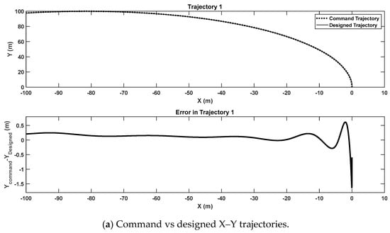
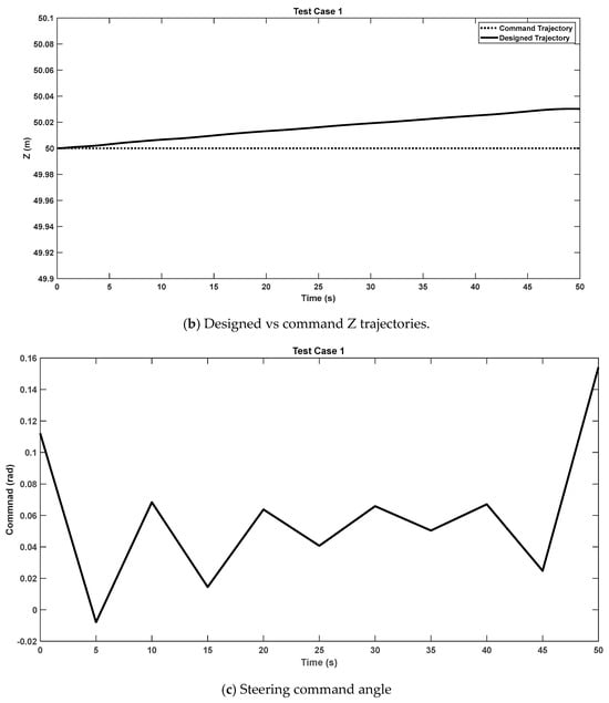
Figure 5.
Test Case 1—circular arc without time constraints trajectory.
Initially, the trajectory control was handled using six control points. However, to improve the precision of the circular arc, the control scheme was incremented to 11 control points. This additional granularity allowed the PPC to make finer adjustments to its steering angle, thereby improving the positional accuracy and ensuring the PPC closely followed the circular arc in the x–y plane.
This case showcases the robustness of the proposed trajectory optimization system in handling simple yet critical flight paths, such as circular trajectories. Maintaining a constant altitude while accurately following a circular path can be important for applications like aerial surveillance, area mapping, or monitoring, where positional precision is critical and timing may be less of a priority.
4.2. Time-Stamped Waypoints on a Circular Arc Trajectory
In this scenario, the powered parachute (PPC) is tasked with visiting six specific waypoints, each associated with a predetermined time (time-stamped waypoints), which form a circular arc. The PPC must reach these waypoints at intervals of 15 s: the first waypoint at 0 s, the second at 15 s, and so on at 30, 45, 60, and 75 s. The challenge involves accurately navigating the PPC along this path while meeting both spatial and temporal constraints.
The optimization process is guided by a cost function, outlined in Box 2, that balances two key factors: the positional error in reaching each waypoint and the error in timing at each waypoint. This dual-objective cost function ensures that the PPC adheres closely to both the required trajectory and the specified timeline.
Box 2. Case 2: cost function.
Case 2: Cost function for waypoints optimization:
F1 = ∑|Psim − Prequired| (summation over the six waypoints)
where Psim denotes PPC position for the optimized trajectory from simulation at a specified time (0 s, 15 s, 30 s, 45 s, 60 s, 75 s).
Prequired represents the PPC position at the specified waypoint
Figure 6a presents the alignment between the commanded and optimized trajectories in the x–y plane, demonstrating close correspondence between the two paths. Figure 6b shows the matching in the z-component over time, further illustrating the PPC’s ability to maintain accuracy in a three-dimensional space. Figure 6c shows the error in the x, y, and z directions in meters. Finally, Figure 6d depicts the command steering angle over time, highlighting the control adjustments needed to maintain trajectory precision and timing.
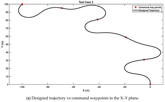
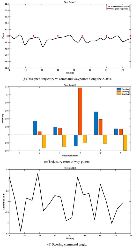
Figure 6.
Test Case 2—time-stamped waypoints trajectory.
To meet these requirements, the control strategy underwent multiple refinements. Initially, the control scheme used six control points, but to improve accuracy, it was incrementally increased to 11 control points and then further extended to 21 control points. This stepwise enhancement in the control complexity allowed for more precise adjustments, enabling the PPC to meet both spatial and temporal constraints with high accuracy.
4.3. Optimal Time Destination with Obstacles Trajectory
In this scenario, the powered parachute (PPC) is assigned to reach a designated target at the coordinates (x = −100 m, y = 100 m, z = 50 m), while avoiding obstacles and minimizing the overall travel time. Three obstacles were introduced (modeled as circular cylinders) at the x–y coordinates (−70, 70), (−30, 30), and (−14, 80). They have radii of 16.1 m, 25.1 m, and 15.1 m, respectively. The optimization process is governed by a cost function, detailed in Box 3, which comprises three key components: the error in the final position, total trajectory time, and penalties for crossing obstacles. This multi-objective cost function ensures that the PPC follows an efficient and safe path to its destination.
Box 3. Case 3: cost function.
| 1- Cost function for trajectory optimization: |
| where Psim denotes PPC simulated final position. |
| Prequired denotes the command final position. |
| 2- Cost function for time minimization |
| where T is the simulation time in seconds to reach the final position |
| 3- Penalty for obstacles |
| F3 is a penalty function defined based on the shape of obstacles. Algorithm is explained in Algorithm 3. |
| 4- Total Cost fitness function F = a F1 + b F2 + c F3 |
| where a, b, and c are weights determined by the type of trajectory required |
| Algorithm 3. Penalty for obstacles calculation algorithm |
| Initialization: All obstacles are modeled as circular cylinders. BEGIN Run simulator with IGA generated input and collect PPC position and time date. Set F3 = 0 FOR time = 0 to Final-time Compare x-y position of PPC with Position of the x-y centers of all obstacles IF (PPC position is inside one of the obstacles) DO BEGIN Add large number to F3 F3 = F3 + 1010 END END FOR LOOP Pass final F3 value to Cost Function |
Figure 7a illustrates the multi-objective optimized trajectories in the x–y plane, demonstrating time-minimum and obstacle avoidance success. The z-component also shows high accuracy, with the final destination error measuring just 16 cm, or 0.32%, indicating the system’s precision. The results confirm that the proposed trajectory planning method successfully meets the target criteria with minimal errors.
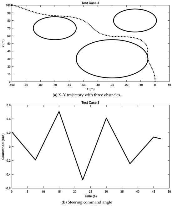
Figure 7.
Test Case 3—optimal time destination with obstacles trajectory.
Figure 7b provides a time-based plot of the command steering angle, showcasing the adjustments made to ensure trajectory optimization. To achieve the desired accuracy and obstacle avoidance, the control scheme was incremented from six control points to eleven, highlighting the adaptability of the optimization process in handling more complex trajectories.
5. Conclusions
This study addresses the research gap in the development of cost-effective and efficient automated aerial delivery systems by focusing on the potential of powered parachutes (PPCs). The objective was to optimize PPC trajectories using an Incremental Genetic Algorithm and assess their effectiveness through simulations. Using a six-degree-of-freedom (6-DOF) dynamic model, this study demonstrated that PPCs can achieve precise flight control with minimal complexity, relying solely on the steering angle input. The simulation results validated the adaptability and accuracy of PPCs across various 3D trajectories and delivery scenarios, underscoring their suitability for remote or hazardous environments.
The results highlight the practicality of PPC systems due to their simplicity, scalability, and reduced infrastructure requirements. These characteristics make them highly applicable to remote area logistics, disaster relief, and military operations. The optimized trajectories further extend the feasibility of PPCs for cost-sensitive and challenging applications, positioning them as a competitive alternative in automated air logistics.
6. Limitations and Future Work
This research is limited to simulation-based testing and does not include real-world experiments. Future studies should validate these results under operational conditions to confirm their reliability. Enhancements to the control system, such as incorporating throttle control and parafoil adjustments, could improve maneuverability and responsiveness in dynamic environments. Additionally, addressing environmental challenges, including wind disturbances and turbulence, will be essential to enhance the robustness and reliability of PPC systems. These advances will further establish PPCs as a practical and sustainable solution for modern air delivery systems.
Author Contributions
Conceptualization, H.M.O.; Methodology, A.H.K.; Formal analysis, H.M.O.; Investigation, H.M.O. and A.H.K.; Writing – review & editing, H.M.O. and A.H.K. All authors have read and agreed to the published version of the manuscript.
Funding
This research received no external funding.
Data Availability Statement
The original contributions presented in the study are included in the article, further inquiries can be directed to the corresponding author.
Acknowledgments
The researchers would like to thank the Deanship of Graduate Studies and Scientific Research at Qassim University for financial support (QU-APC-2025).
Conflicts of Interest
The authors declare no conflict of interest.
References
- Betti Sorbelli, F. UAV-Based Delivery Systems: A Systematic Review, Current Trends, and Research Challenges. J. Auton. Transp. Syst. 2024, 1, 1–40. [Google Scholar] [CrossRef]
- Nicolaides, J.D.; Speelman, R.J.; Menard, G.L.C. A review of para-foil applications. J. Aircr. 1970, 7, 423–431. [Google Scholar] [CrossRef]
- Beard, R.W.; McLain, T.W. Small Unmanned Aircraft: Theory and Practice; Princeton University Press: Princeton, NJ, USA, 2012. [Google Scholar]
- Hailey, T.I. The powered parachute as an archaeological aerial reconnaissance vehicle. Archaeol. Prospect. 2005, 12, 69–78. [Google Scholar] [CrossRef]
- Slegers, N.; Costello, M. Aspects of control for a parafoil and payload system. J. Guid. Control Dyn. 2003, 26, 898–905. [Google Scholar] [CrossRef]
- Iacomini, C.; Cerimele, C. Longitudinal aerodynamics from a large scale parafoil test program. In Proceedings of the 15th Aerodynamic Decelerator Systems Technology Conference, Toulouse, France, 8–11 June 1999; p. 1732. [Google Scholar]
- Gang, Y. Nine-degree of freedom modeling and flight dynamic analysis of parafoil aerial delivery system. Procedia Eng. 2015, 99, 866–872. [Google Scholar] [CrossRef][Green Version]
- García-Beltrán, C.; Miranda-Araujo, E.; Guerrero-Sanchez, M.; Valencia-Palomo, G.; Hernández-González, O.; Gómez-Peñate, S. Passivity-based control laws for an unmanned powered parachute aircraft. Asian J. Control 2021, 23, 2087–2096. [Google Scholar] [CrossRef]
- Slegers, N.; Costello, M. Comparison of measured and simulated motion of a controllable parafoil and payload system. In Proceedings of the AIAA Atmospheric Flight Mechanics Conference and Exhibit, Austin, TX, USA, 11–14 August 2003; p. 5611. [Google Scholar]
- Novak, D. Drone (s) Trajectory Optimization for Mapping Missions. Ph.D. Thesis, Université Paris-Saclay, Gif-sur-Yvette, France, 2024. [Google Scholar]
- Aoustin, Y.; Martynenko, Y. Control Algorithms of the Longitude Motion of the Powered Paraglider. In Proceedings of the ASME 2012 11th Biennial Conference on Engineering Systems Design and Analysis, Nantes, France, 2–4 July 2012. [Google Scholar]
- Chambers, J. Longitudinal Dynamic Modeling and Control of Powered Parachute Aircraft. Master’s Thesis, Rochester Institute of Technology, Rochester, NY, USA, 2007. [Google Scholar]
- Devalla, V.; Prakash, O. Developments in unmanned powered parachute aerial vehicle: A review. IEEE Aerosp. Electron. Syst. Mag. 2014, 29, 6–20. [Google Scholar] [CrossRef]
- Kumar, P. Design and Development of Autonomous Lightweight Powered Paraglider. Master’s Thesis, Indian Institute of Technology, Chennai, Indian, 2014. [Google Scholar]
- Kumar, P.; Choudhury, B.; Singh, A.; Ramkumar, J.; Philip, D.; Ghosh, A.K. Modeling and prediction of powered parafoil unmanned aerial vehicle throttle and servo controls through artificial neural networks. Drone Syst. Appl. 2023, 11, 1–16. [Google Scholar] [CrossRef]
- Slegers, N.; Costello, M. Model predictive control of a parafoil and payload system. J. Guid. Control Dyn. 2005, 28, 816–821. [Google Scholar] [CrossRef]
- Kumar, P.; Sonkar, S.; Ghosh, A.K.; Philip, D. Dynamic Waypoint Navigation and Control of Light Weight Powered Paraglider. In Proceedings of the 2020 IEEE Aerospace Conference, Big Sky, MT, USA, 7–14 March 2020; pp. 1–8. [Google Scholar]
- Binz, F.; Hartmann, P.; Moormann, D. Nonlinear model predictive flight path control for an unmanned powered paraglider. In Proceedings of the Advances in Aerospace Guidance, Navigation and Control: Selected Papers of the Fourth CEAS Specialist Conference on Guidance, Navigation and Control Held in Warsaw, Poland, April 2017; Springer: Cham, Switzerland, 2018; pp. 369–387. [Google Scholar]
- Alharasees, O.; Adali, O.H.; Kale, U. Human Factors in the Age of Autonomous UAVs: Impact of Artificial Intelligence on Operator Performance and Safety. In Proceedings of the 2023 International Conference on Unmanned Aircraft Systems (ICUAS), Warsaw, Poland, 6–9 June 2023; pp. 798–805. [Google Scholar]
- Alharasees, O.; Kale, U. Aviation Operators’ Total Loads Analysis by Multi-Criteria Decision-Making. J. Air Transp. Manag. 2024, 118, 102596. [Google Scholar] [CrossRef]
- Yıldırım Dalkıran, F.; Kırteke, E. Design and Implementation of A Low-Cost Parachute Landing System for Fixed-Wing Mini Unmanned Aerial Vehicles. J. Aviat. 2024, 8, 198–205. [Google Scholar] [CrossRef]
- Raj, D.; Sada, S.K.; Raut, A.; Chundawat, C.S.; Patidar, V.K.; Nizama, V.; Sethi, V. Gujarat, design and fabrication of sweepback parachute. AIP Conf. Proc. 2024, 3107, 020002. [Google Scholar]
- Kassem, A.H. Trajectory Optimization via Simulation Using Incremented Genetic Algorithms. Can. Aeronaut. Space J. 2006, 52, 15–20. [Google Scholar] [CrossRef]
- Iyer, P.G. Modelling of a 12-DoF Parachute–Riser–Payload system dynamics using Kane’s method. Multibody Syst. Dyn. 2024, 60, 599–619. [Google Scholar] [CrossRef]
- Zhao, J.; Li, S. Mars atmospheric entry trajectory optimization with maximum parachute deployment altitude using adaptive mesh refinement. Acta Astronaut. 2019, 160, 401–413. [Google Scholar] [CrossRef]
- Li, Z.; Nan, Y. Optimal Path Planning and Tracking Control Methods for Parafoil. Appl. Sci. 2023, 13, 8115. [Google Scholar] [CrossRef]
- Rademacher, B.J.; Lu, P.; Strahan, A.L.; Cerimele, C.J. In-flight trajectory planning and guidance for autonomous parafoils. J. Guid. Control Dyn. 2009, 32, 1697–1712. [Google Scholar] [CrossRef]
- Toglia, C.; Vendittelli, M.; Lanari, L. Path following for an autonomous paraglider. In Proceedings of the 49th IEEE Conference on Decision and Control (CDC), Atlanta, GA, USA, 15–17 December 2010; pp. 4869–4874. [Google Scholar]
- Strickert, G.; Jann, T. Determination of the relative motion between parafoil canopy and load using advanced video-image processing techniques. In Proceedings of the 15th Aerodynamic Decelerator Systems Technology Conference, Toulouse, France, 8–11 June 1999; p. 1754. [Google Scholar]
- Strickert, G.; Witte, L. Analysis of the relative motion in a parafoil-load system. In Proceedings of the 16th AIAA Aerodynamic Decelerator Systems Technology Conference and Seminar, Boston, MA, USA, 21–24 May 2001; p. 2013. [Google Scholar]
- Umenberger, J.; Göktoğan, A.H. Guidance, navigation and control of a small-scale paramotor. In Proceedings of the Australasian Conference on Robotics and Automation (ACRA), Wellington, New Zealand, 3–5 December 2012; pp. 3–5. [Google Scholar]
- Müller, M.; Ali, A.; Tareilus, A. Modelling and simulation of a paraglider flight. In Proceedings of the 9th EUROSIM Congress on Modelling and Simulation, Oulu, Finland, 12–16 September 2016. [Google Scholar]
- Li, Y.; Zhao, M.; Yao, M.; Chen, Q.; Guo, R.; Sun, T.; Jiang, T.; Zhao, Z. 6-DOF modeling and 3D trajectory tracking control of a powered parafoil system. IEEE Access 2020, 8, 151087–151105. [Google Scholar] [CrossRef]
- Zipfel, P.H. Modeling and Simulation of Aerospace Vehicle Dynamics; American Institute of Aeronautics and Astronautics: Reston, VA, USA, 2014. [Google Scholar]
- Omar, H.M. Optimal geno-fuzzy lateral control of powered parachute flying vehicles. Aerospace 2021, 8, 400. [Google Scholar] [CrossRef]
Disclaimer/Publisher’s Note: The statements, opinions and data contained in all publications are solely those of the individual author(s) and contributor(s) and not of MDPI and/or the editor(s). MDPI and/or the editor(s) disclaim responsibility for any injury to people or property resulting from any ideas, methods, instructions or products referred to in the content. |
© 2025 by the authors. Licensee MDPI, Basel, Switzerland. This article is an open access article distributed under the terms and conditions of the Creative Commons Attribution (CC BY) license (https://creativecommons.org/licenses/by/4.0/).