1. Introduction
With the continuous advancement of human science and technology, the demand for and interest in outer space exploration have been steadily increasing. To ensure the success and reliability of these endeavors, planetary rovers play a crucial role as essential exploration tools. The planetary rovers can effectively expand the scope of exploration, and the design and performance research for planetary rovers are indispensable.
Currently, rovers have successfully landed on the Moon and Mars, with most surfaces covered by soft terrain that presents significant mobility challenges. Soft media, which are highly fluid, often cause difficulties for planetary rovers when driving [
1]. The United States Opportunity, Spirit, Curiosity and Sojourner Mars rovers have all faced passing problems, such as deep depression or high slip [
2,
3,
4]. Suspension structures and control strategies can improve rover trafficability. Spirit used a strategy of moving its wheels forward and backward with steering assistance to avoid sinkage. However, it took several months to get out of sinkage, and it eventually failed after the fourth time [
5]. Drawing from the failure experiences, China’s Zhurong rover utilizes an active suspension and peristaltic disengagement strategy to enhance passability [
6]. To address sinkage and slip issues that affect planetary rover mobility, various prediction and control methods have been proposed in recent years. Based on the similarity model and superposition principle, the sinkage prediction model [
7,
8] is proposed, and the soil flow is calculated by the sinkage sensor [
9] to predict the sinkage area, which provides a theoretical basis for control in high slip and high sinkage environments. Through visual detection, such as sinkage estimation methods [
10] and a monocular camera [
11,
12,
13], the risk of high sinkage and high slip is judged and reduced. Reasonable path planning can effectively avoid high slip problems. A robust path planning algorithm [
14], microsecond slip estimation framework [
15], slip rate regression model [
16], etc., all help improve the efficiency of path planning. In terms of slip estimation and prediction, data-driven methods [
17,
18], thermal inertial measurement [
19], Gaussian process regression estimation model [
20] and machine learning, combined with visual data [
21], have significantly improved the accuracy of path planning. These studies provide favorable support for the safety and passing ability of the planetary rover in complex terrain. Improving the passability of planetary rovers and ensuring smooth operation remain significant technical challenges [
22,
23].
Up to now, the planetary rovers that have successfully landed in outer space have adopted a wheeled structure. Wheeled planetary rovers are still widely used due to their simple structure and high stability. As the core component in direct contact with the planetary surface, the wheel directly affects the driving performance and trafficability of the planetary rover [
24]. In the harsh environment of outer space, planetary rovers face extreme climates, radiation and large temperature fluctuations, which render conventional inflatable tires impractical. Therefore, rigid metal wheels are widely used in the current unmanned planetary rovers to cope with the harsh conditions of the outer space environment.
Over the years, continuous research has been carried out on rigid wheels used in soft terrain to improve the adaptability and reliability of planetary rovers in various terrains. Based on the wheel–soil relationship theory of traditional ground mechanics, the wheel–soil mechanical model under the soft terrain of outer planetary bodies is optimized [
25,
26]. The wheel sinkage [
27], wheel–soil force [
28] and wheel dynamic wheel–soil relationship [
29] are discussed in depth, which provides theoretical guidance for the design of planetary wheels. The trafficability of the wheel is improved by optimizing the design of the rigid wheel structure [
30,
31]. In [
32], the design guideline, the number of wheel grousers of rigid planetary rover wheels, is also proposed through testing. Through DEM simulation and analysis, we can further study the relationship between wheel and soil, study the traction performance of wheels [
33] and study the movement behavior in the wheel and soil particle field [
34] so as to improve the adaptability of wheels to granular soil. Whether it is wheel design, wheel–soil relationship research or DEM (Discrete Element Method) simulation, it can be verified by experimental methods. As an extensive and reliable method, the experimental method can effectively study the key characteristics of wheel motion behavior [
35], sinkage behavior [
36] and so on.
With the increasing demand for human exploration of outer space, the research and design of planetary rovers are particularly important. From the above research, it can be seen that the planetary rover wheel, as the main source of trafficability, is of great significance to this research. The planetary rover wheel needs to have the ability to get out of sinkage, climb slopes, cross obstacles, etc. and has sufficient driving, bearing and traction capabilities. At present, there are few studies evaluating the performance of rigid wheels through specific tests. In this paper, three kinds of wheels with the same basic size and completely different wheel grousers and tread structures are selected to measure different basic performance parameters through single-wheel tests. Three kinds of terrain tests, obstacle crossing, getting out of sinkage and climbing, are carried out to analyze the specific details of the different structures. Through the test results, the advantages and disadvantages of rigid metal wheels with different structures in different terrains are summarized.
2. Test Wheels
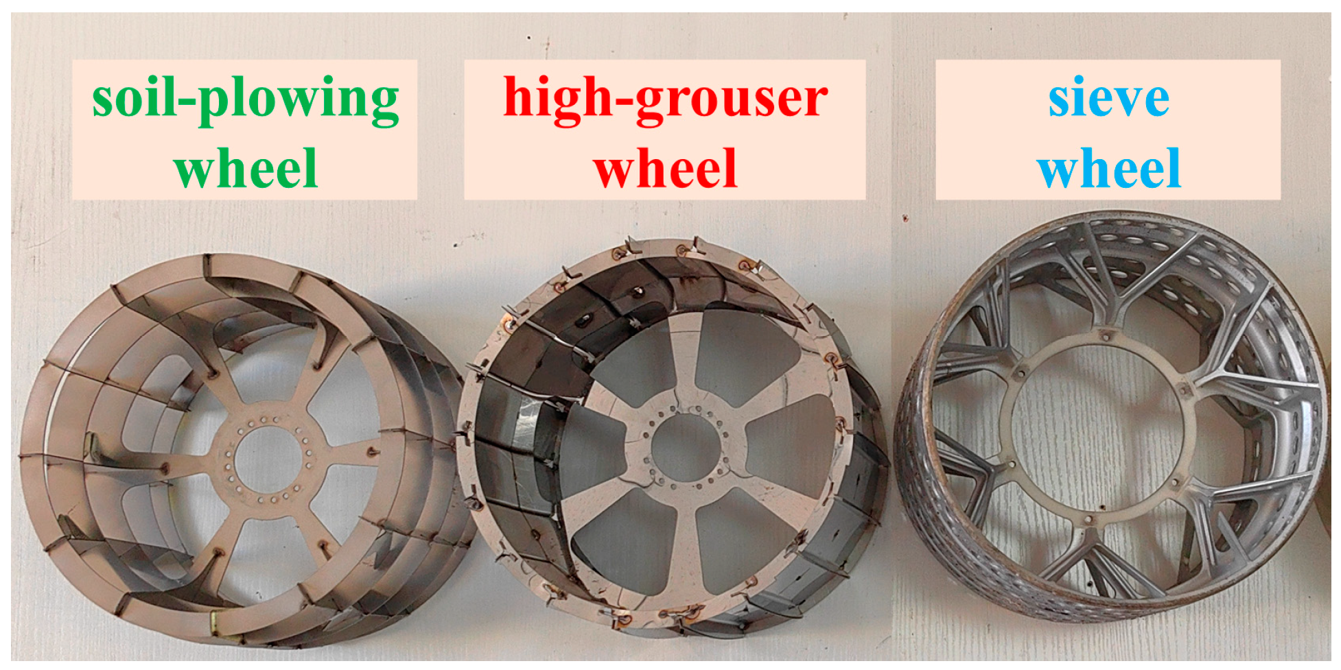
On soft terrain, planetary rovers typically employ arched wheels with grousers. In this paper, three types of wheels featuring novel and distinctive surface characteristics are selected. These wheels are all based on the arched wheel design, with optimizations made to the wheel surface, including the tread and grouser structures. To meet the test conditions, the wheels are scaled according to the equivalent principle based on the load of the existing planetary rover and the structural dimensions of the rigid wheel. The wheels in this study are all 250 mm in diameter and 160 mm in width.
Wheel 1 is a soil-plowing wheel [
37], which has no tread structure and consists of 12 soil-plowing pieces, 4 beads and 1 spoke. The beads have an inner diameter of 200 mm, with outer diameters of 240 mm and 250 mm. The working width of the soil-plowing piece is 160 mm, the working height of the soil-plowing piece is 25 mm and the outer end of the working height direction forms an arch structure. The wheel has no tread structure, both sides are closed and it has wheel grousers. During driving, the grousers disturb the soil and outflow inside the wheel. The wheel gathers the soil through the soil-plowing pieces and the rims on both sides, limiting the soil to flow outward from both sides to obtain the driving force.
The high-grouser wheel is designed based on the tread characteristics of the Viper wheel developed by NASA [
38]. It consists of a tread, wheel grousers, spokes and rim structures. The outer edge of the wheel flange is higher than the tread and is connected to the wheel grousers and tread, forming a continuous, closed structure with the flange, tread and wheel grousers on both sides. The tread and grousers are integrated as a single unit, comprising 18 pieces in total, along with 2 rims and 1 spoke. The outer diameter of the rim is 242 mm, with an inner diameter of 220 mm. The outer edge of the wheel grousers is curved in an arched contour. The wheel has a tread structure, is closed on both sides and has a wheel grouser structure. During the driving process, the wheel grouser disturbs the soil and gathers the soil through the closed rim and tread on both sides. The wheel gathers soil through the grousers, the tread and the rims on both sides, limiting the flow of soil from the inside and on both sides of the tire to obtain the driving force.
The sieve wheel [
39,
40,
41] has no wheel grouser structure, and there are sieve holes on the surface of the tread. It is composed of a tread, spokes and support rib structure. The tread is a micro-arch structure. The diameter of the highest point on the outer surface of the tread section is 250 mm, and the diameter of the edges on both sides is 240 mm. The tread profile is formed by drawing an arc through three points, and the outer surface of the tread is created by rotating this arc 360°. The tread has a thickness of 2 mm, with evenly distributed circular holes of 15 mm in diameter. The wheel features a sieve-hole tread structure but lacks a wheel grouser structure. During the driving process, the tread contacts the soil, generates a certain friction force and disturbs the soil through the sieve to obtain the driving force.
The wheels of the real planetary rover are all made of metal materials. Considering the processing cost, the soil-plowing wheel and the high-grouser wheel are easier to process, using 201 stainless steel material production. However, due to the holes in the arched tread of the sieve wheel, metal processing techniques are challenging and costly. The main purpose of this test is to study the passing ability of different kinds of rigid wheels. The wheel material has little effect on the passability. Therefore, the influence of the material on the test is not considered. The sieve wheel is manufactured using R4600 photosensitive resin via 3D printing. To facilitate subsequent tests, the size and weight of each wheel are measured. The relevant parameters for each test wheel are presented in
Table 1, and the final processing of each wheel is shown in
Figure 1. Since the high-grouser wheel includes both a tread and a grouser structure, its overall weight is relatively high.
3. Wheel Performance Parameter Measurement Test
3.1. Sinkage and Slip Rate
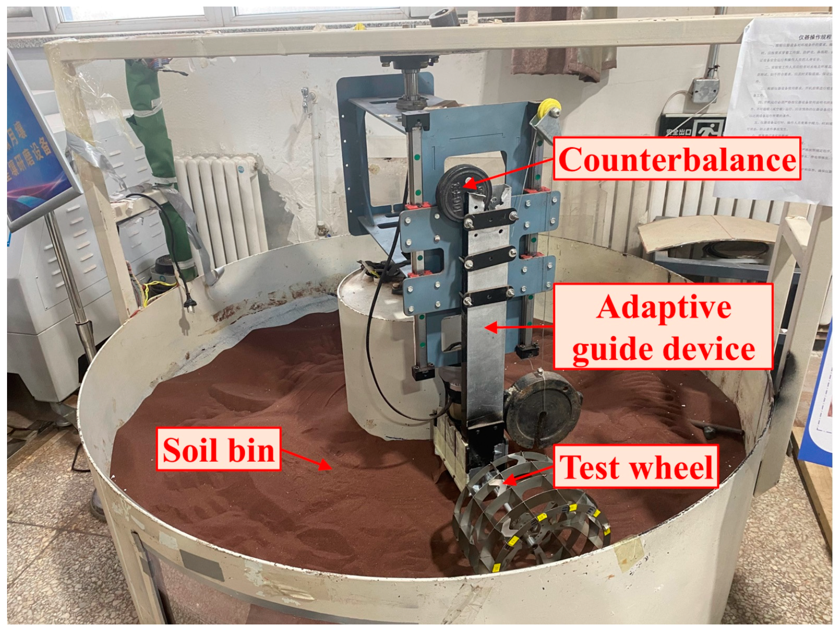
The wheel sinkage and slip rate were measured by the circular soil bin test bench (
Figure 2). The test bench is mainly composed of a control computer, a ring soil bin, a rotary test bench, a drive system and an adaptive guide device. The wheel rotates actively through the drive motor, and the maximum test wheel velocity was 25 rpm. The inner diameter of the soil trough was 420 mm, the outer diameter was 1650 mm and the depth was 600 mm. The JLU-Mars2 simulated planetary soil was laid in the test bench, and its main physical and mechanical parameters are shown in
Table 2 [
42]. Each test was repeated three times, and the final test data were obtained by calculating the mean value. To ensure repeatability and consistency of the test, the simulated soil was loosened, scraped and prepared, and the height was detected before each test.
According to the load and velocity of the lunar rover in the lunar environment, the normal load on the wheel is 50 N, 60 N, 70 N, 80 N, 90 N and 100 N when the wheel velocity is 0.1885 km/h. When the normal load of the wheel is 50 N, the wheel velocity is 0.0471 km/h, 0.0943 km/h, 0.1414 km/h, 0.1885 km/h and 0.2356 km/h. The sinkage and slip rate of each wheel were obtained through experiments (
Figure 3).
In soft terrain, the average sinkage of WH1 was 20.0 mm, WH2 was 16.9 mm and WH3 was 10.63 mm. The sinkage of WH1 was positively correlated with both load and velocity, with a significant influence from these factors. Because WH1 has no tread structure, the load increases, and thus, sinkage also increases. Additionally, as velocity increases, the soil movement accelerates, loosening the soil beneath the wheel, which results in further sinkage. The sinkage of WH2 is primarily influenced by the load, which increases with higher loads and is less affected by driving velocity. As the load increases, the sinkage of WH2 also increases, but when the wheel’s sinkage reaches a certain threshold, the contact area between the tread and the soil expands, and the change in sinkage with load becomes less noticeable. WH2 has a tread structure; the wheel velocity has little effect on the force of the supporting wheel generated by the soil, and it has little effect on the wheel sinkage. WH3’s sinkage is less affected by the load and more affected by the driving velocity, which is positively correlated with the velocity. WH3 has no wheel grouser structure; the tread is in direct contact with the soil, and the sinkage is small. The load has little effect on the wheel sinkage; the wheel velocity increases the damage of the soil under the WH3 wheel, and the wheel sinkage increases.
In soft terrain, the average slip rate of WH1 was 17.73%, WH2 was 6.05% and WH3 was 4.78%. When the wheel moves on soft ground, the soil undergoes shear deformation when providing thrust, and wheel slip is an inevitable phenomenon. The slip rate of WH1 is greatly affected by load and wheel velocity. WH1 has high sinkage characteristics when driving on soft ground, which causes large shear damage to the soil, and the slip rate is much higher than that of the other two wheels. As the load increases, the driving force required for WH1 increases, and it is necessary to increase the shear failure of the soil so the slip rate gradually increases. As velocity increases, so does the amount of WH1 sinkage, the number of wheel grousers disturbed in the soil, and the ability to obtain the driving force. The single soil sheet’s disturbance to the soil decreases, and the slip rate gradually decreases as well. The slip rate of WH2 is less affected by load and velocity, but because WH2 has a wheel structure, it causes shear damage to the soil, and the slip rate is higher than that of WH3. Because of the non-wheel grouser structure, WH3 causes less damage to the soil and has a lower slip rate; the slip rate is less affected by load and driving velocity.
3.2. Traction Coefficient
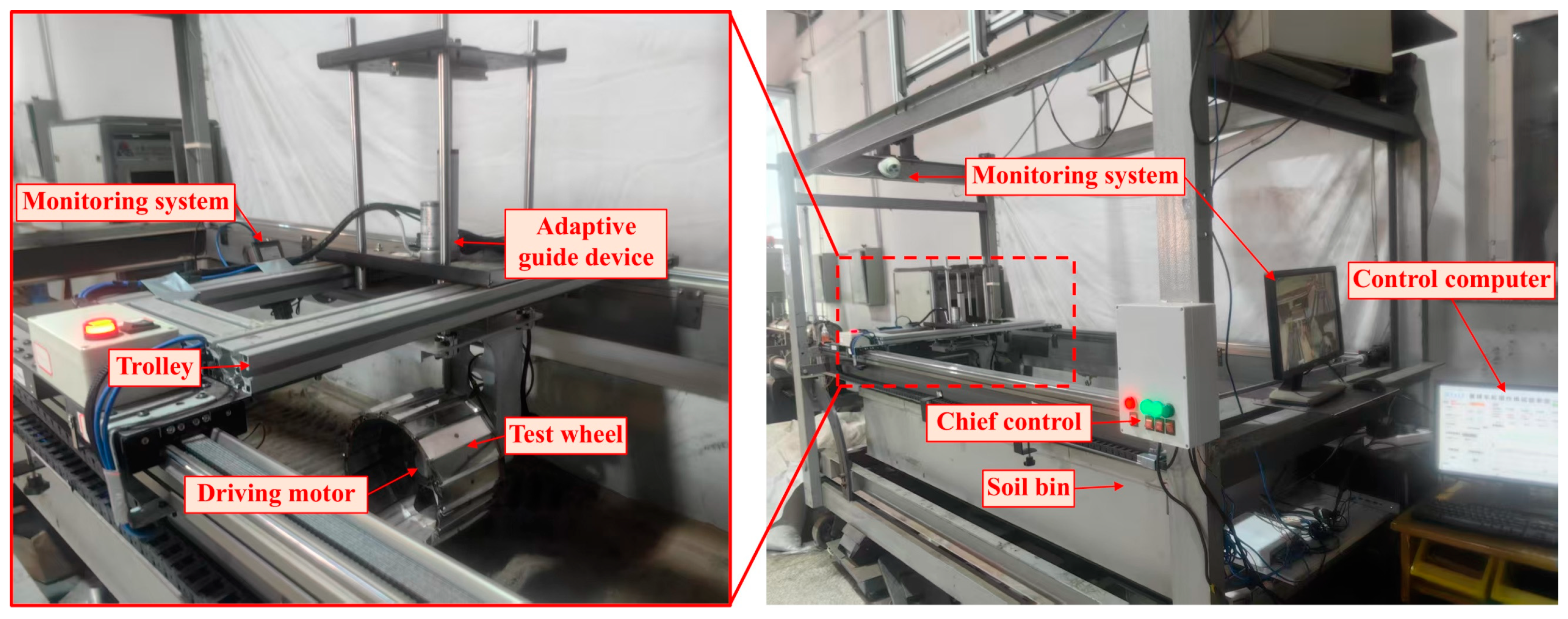
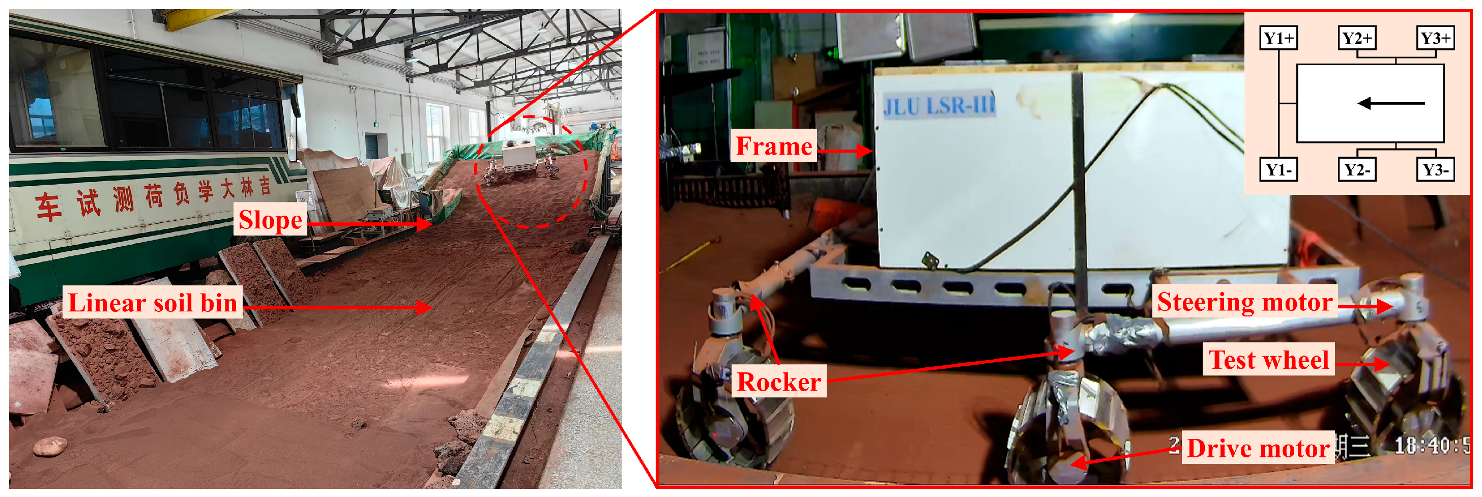
In order to measure the wheel’s traction coefficient, the linear soil bin test bench was modified. After the transformation, the test bench was mainly composed of a control computer, linear soil bin, drive trolley, adaptive bench and drive system (
Figure 4). The soil bin measured 1500 mm in length, 800 mm in width and 400 mm in height. The slip rate can be set by driving the trolley and the wheel. The maximum velocity of the trolley is 100 mm/s, and the maximum velocity of the test wheel is 25 rpm. The JLU-2b simulated planetary soil was laid in the soil bin, and its main physical and mechanical parameters are shown in
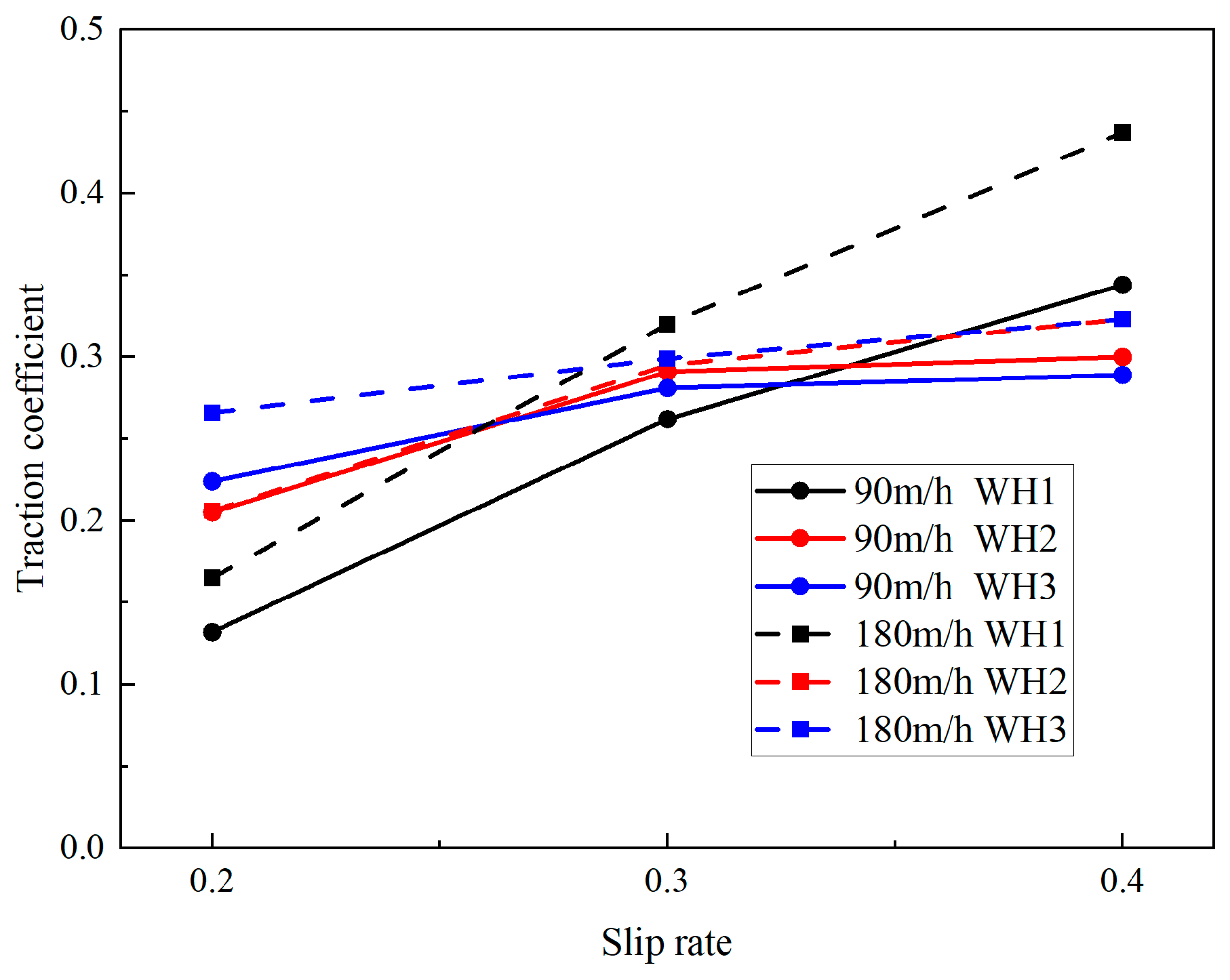
Table 3. In order to ensure the repeatability and consistency of the test, the simulated soil was loosened, scraped and prepared, and the height was detected before each test. According to the load and driving velocity of the rover in the lunar environment, the traction coefficient was measured by the test of the wheel’s normal load of 100 N, the driving velocity of 0.09 km/h, 0.18 km/h and the slip rate of 0.2, 0.3, 0.4. The test was repeated three times to take the mean value, and the results are shown in
Figure 5.
The traction coefficient of each wheel increased with the slip rate and velocity. In contrast, the traction coefficient of WH3 was the least affected by the slip rate, the traction coefficient of WH2 was the least affected by the velocity and the traction coefficient of WH1 increased the most with slip rate and velocity. With the slip rate changing from 0.2 to 0.4, the traction coefficients of WH1, WH2 and WH3 increased by 0.24, 0.11 and 0.06, respectively. With the change in velocity from 0.09 km/h to 0.18 km/h, the traction coefficients of WH1, WH2 and WH3 increased by 0.061, 0.009 and 0.031, respectively.
3.3. Summary
WH1 has no tread structure, and it has the highest sinkage and the highest slip rate during driving. At a low slip rate, the wheel traction coefficient is low, but with the increase in slip rate, the wheel traction coefficient increases significantly. WH2 has a higher sinkage and slip rate due to its higher wheel grouser. However, due to the tread structure, it does not produce wheel sinkage and slip rates that are too high, and the slip rate does not change significantly with the load velocity. The traction coefficient increases with the increased slip rate, but it is not significant. WH3 has a sieve tread without a wheel grouser structure, so the wheel sinkage and slip rate are the lowest. The ability of the wheel to obtain traction on soft terrain is relatively stable; the traction coefficient changes little with the slip rate, and the traction coefficient is not high.
In summary, the grouser structure reduces the equivalent radius of the wheel, increases the sinkage of the wheel, disturbs the soil during driving to increase the slip rate, and increases the traction coefficient of the wheel at a higher slip rate. The tread structure can avoid excessive sinkage and slip rate, but it also reduces the traction coefficient of the wheel under a higher slip rate. The sieve tread has the ability to destroy the soil to obtain the driving force under the soft terrain, and the traction coefficient is slightly increased with the increased slip rate.
4. Terrain Passability Test
4.1. Test Purpose
To study the mobility of each wheel on the soft ground, the test rover with a three-rocker structure was used for the mobility test. In this test, a linear soil trough was used in the Jilin University laboratory. Three kinds of planetary wheels were used as test objects and simulated star soil was used as test medium. The test included three different terrains—obstacle crossing, extricating from sinkage and climbing—to evaluate the overall trafficability of the rover. The test comprehensively considered the complex working conditions of the planetary rover on soft ground, as well as the wheel–soil interaction characteristics of the wheels at different positions. Based on these factors, the passability of the wheels was thoroughly assessed.
4.2. Test Condition
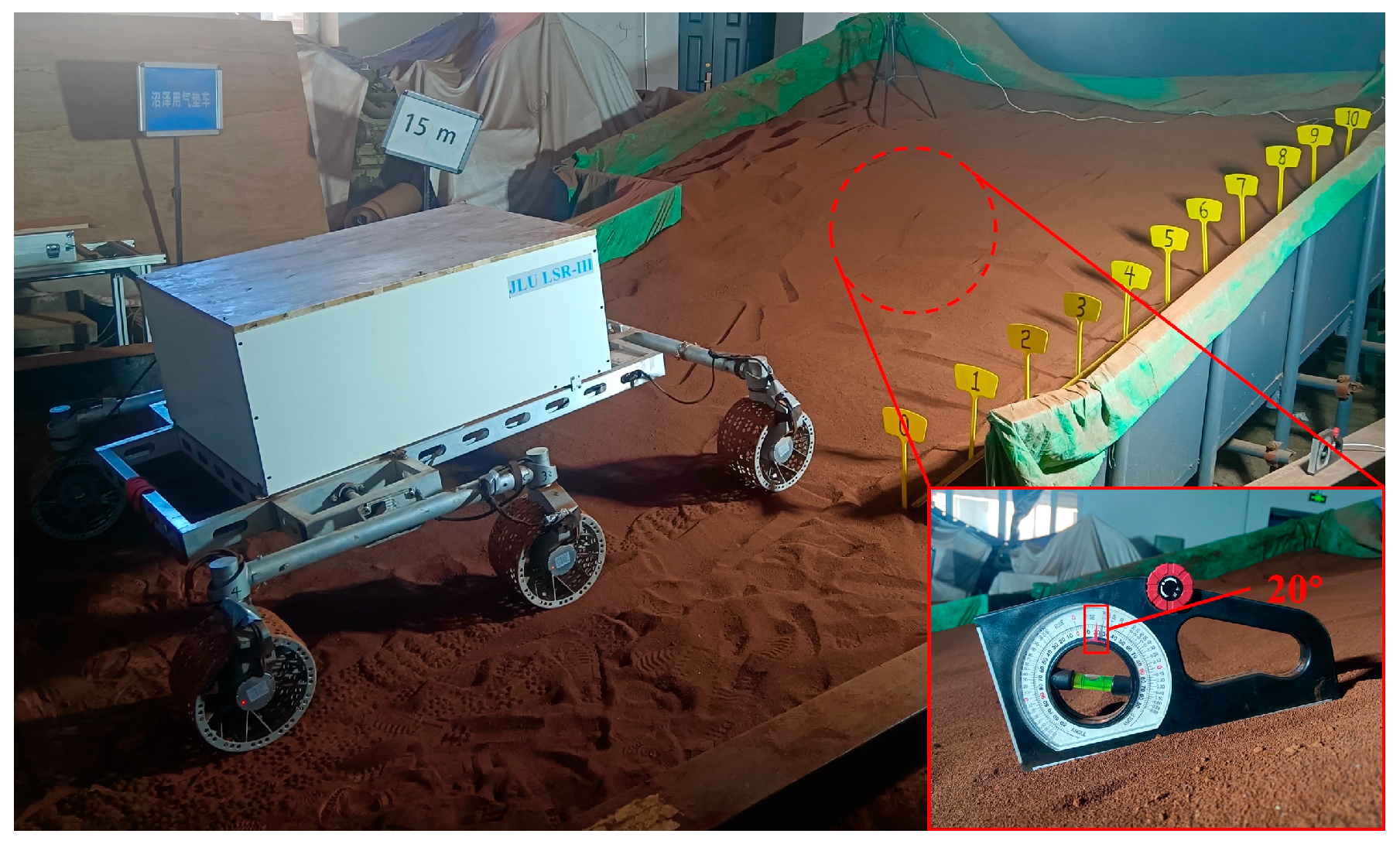
In this test, a linear soil trough (
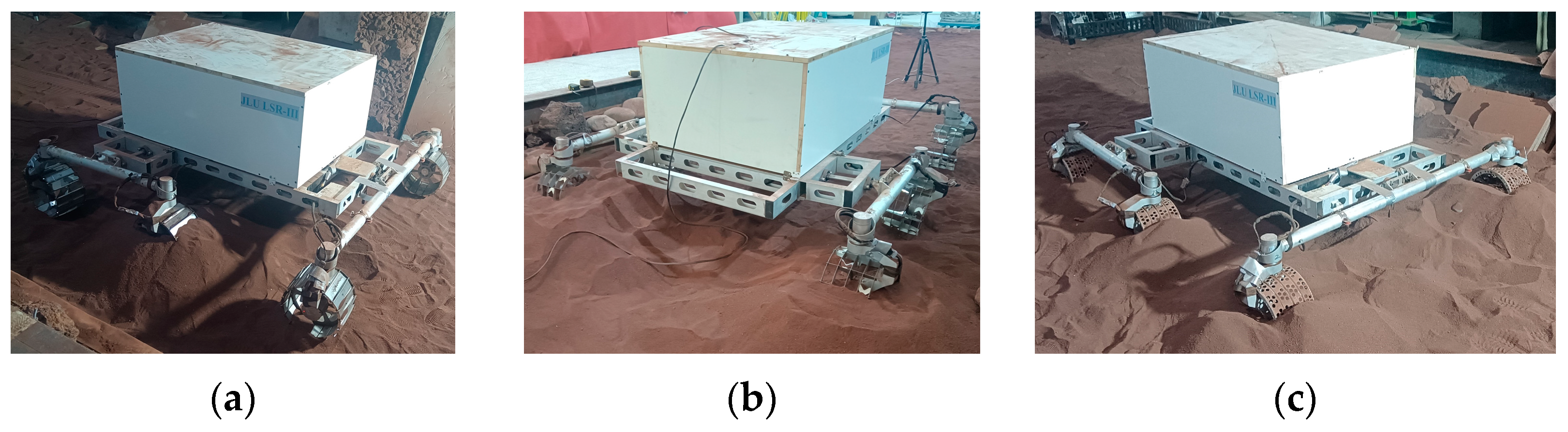
Figure 6) was used in the Jilin University laboratory. The effective volume of the soil trough was 20 m long, 3.5 m wide and 0.6 m deep, including adjustable slopes. Among them, two kinds of simulated star soil (JLU Mars-1 and Mars-2) were laid, and JLU Mars-2 simulated fire soil was laid on the loose slope. This test was carried out on JLU Mars-2 simulated star soil. The three-rocker six-wheeled unmanned planetary rover JLU LSR-III (
Figure 6) was used for the test. The test planetary rover is composed of a body, suspension, steering mechanism and wheels. The test rover has a length of 1750 mm, a width of 1600 mm, a height of 800 mm and a total weight of 36 kg. The test wheel is connected to the drive mechanism by bolts and is easy to replace. Based on the load and velocity of the lunar rover in the lunar environment, the rover velocity was set to 0.18 km/h, and the load was set to 360 N. The test was repeated for three trials.
4.3. Rover Obstacle Crossing Ability Test
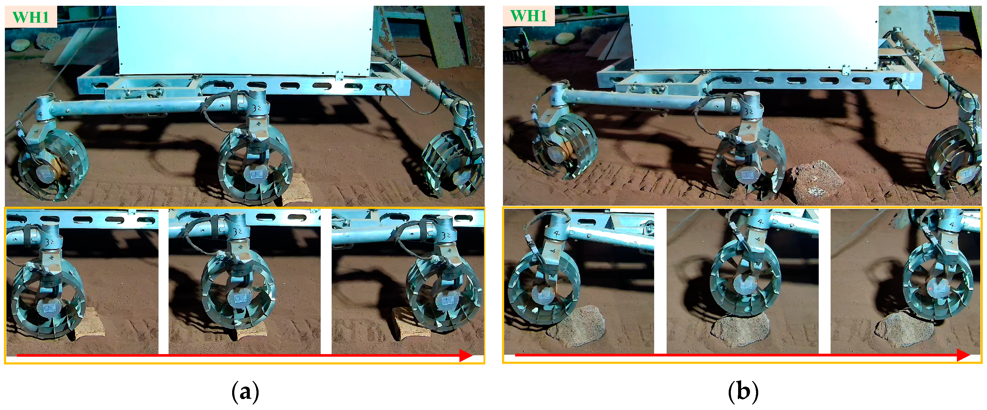
In this test, the obstacle ability of the test rover was judged according to the time when the wheel crossed the stone (
Figure 7). It is divided into two working conditions: one stone on one side and one stone on both sides. It includes the obstacle crossing ability test of a 50 mm high right angle red brick and 100 mm high sharp angle stone. In this test, stones were placed on the front side of the test wheels to ensure that the wheels could cross the obstacle, and the rover only crossed the obstacle in a straight movement.
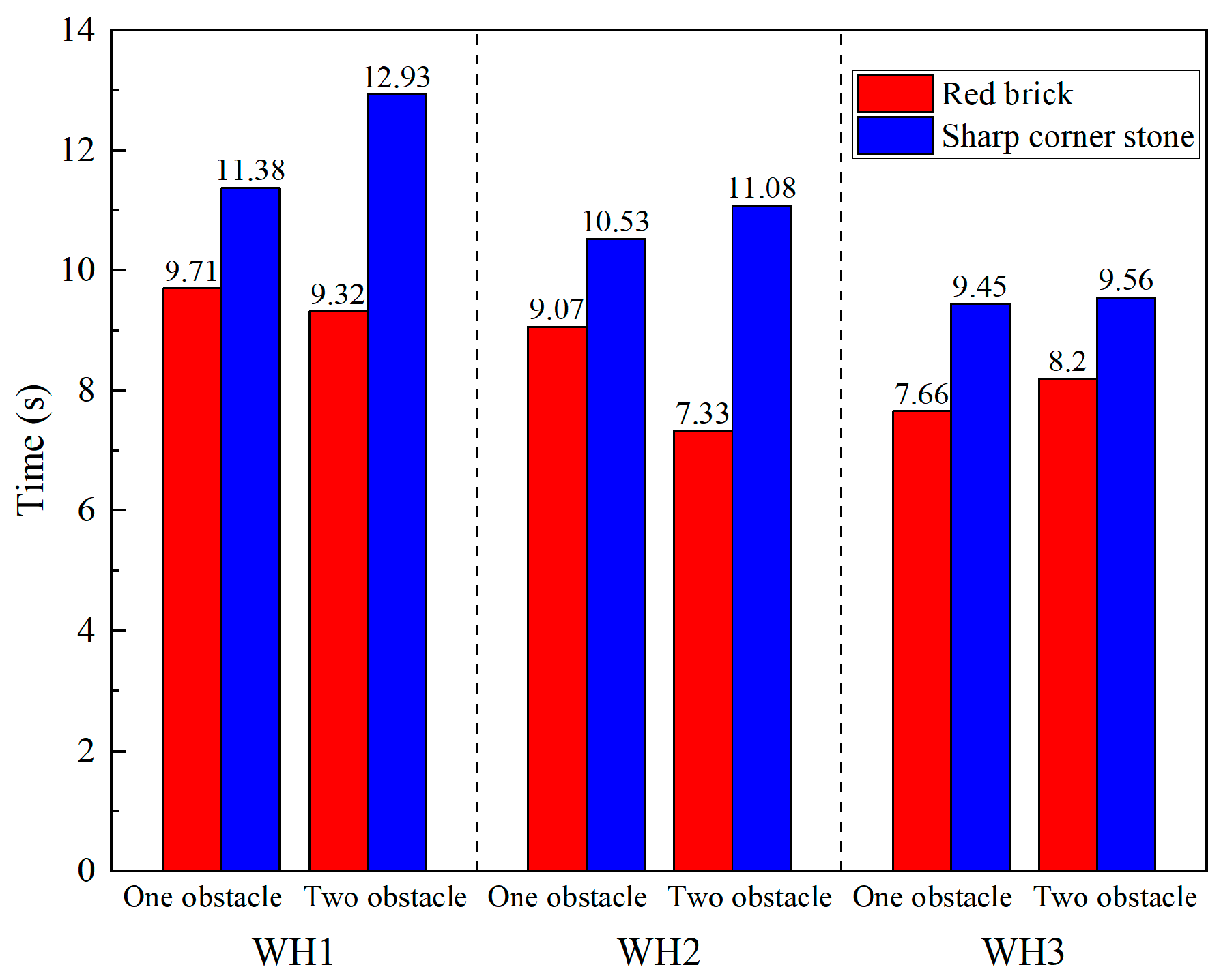
The wheel obstacle crossing time under various working conditions is shown in
Figure 8. The test results indicate that the test rover equipped with WH1, WH2 and WH3 wheels is capable of crossing obstacles in both single-wheel and dual-wheel configurations. The obstacle-crossing ability of all three wheels is better on the 50 mm high red brick terrain compared to the 100 mm sharp corner stone terrain. The obstacle crossing velocity of the test rover with three kinds of wheels was not very different; from fast to slow, it was WH3, WH2 and WH1.
WH3 has no wheel grouser structure. During obstacle crossing, it advances through friction between the tread and the stone. The continuous contact friction between the wheel and the stone is continuous, and the obstacle crossing is the fastest (
Figure 9e,f). WH1 and WH2 move forward by engaging their wheel grousers during obstacle crossing, which creates point or line contact with the stones, resulting in a smaller contact area. During this process, it is possible that the wheels may not always maintain contact with the stone, causing minor slippage, though this does not affect their ability to cross the obstacle (
Figure 9). Since WH2 has more wheel grousers than WH1 and features a tread structure, it is less likely to experience slippage or miss contact with stones, allowing it to cross the obstacle faster. In the red brick terrain, which has distinct edges and low height, the wheels with grousers are more likely to hook and cross the obstacle, resulting in minimal variation in obstacle crossing time between the three wheels. However, in the stone terrain, where the stones lack sharp edges and corners, it is harder for the wheel grousers to engage, making the obstacle crossing time longer. Unlike WH3, which can cross the obstacle through friction, the time gap between the two terrains is small.
4.4. Rover Out-of-Sinkage Ability Test
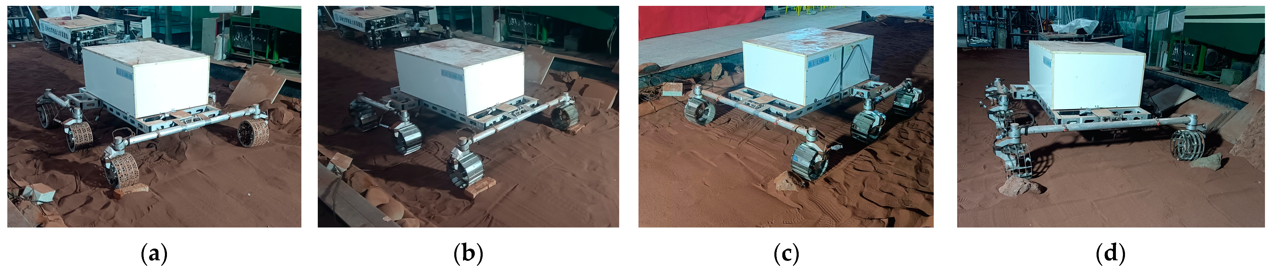
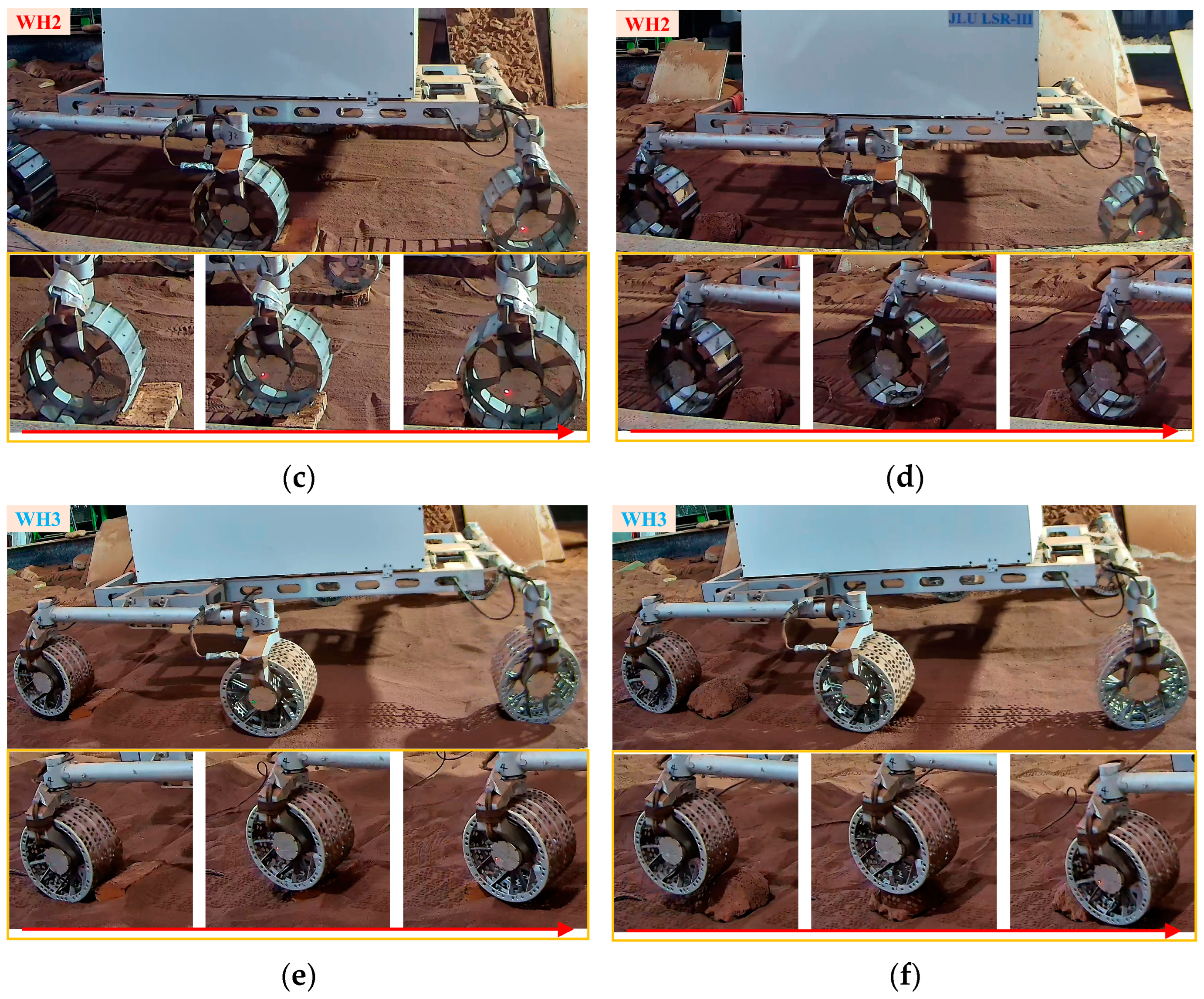
Sinkage relief ability tests were set up for six wheels (full sinkage), single-wheel sinkage, and two-wheel sinkage. By digging a pit with a length of 400 mm, a width of 400 mm and a depth of 200 mm in the test medium, the wheels that needed to be out of the pit were artificially buried in the pit, and the pit was filled to form a sinkage scene. In this test, all the wheels of the rover could be driven. During the test, the planetary rover only drove away from the sinkage environment by straight movement. The ability of the test rover to get out of the sinkage area was judged according to the time when the wheels escaped the pit (
Figure 10).
The test rover with WH1, WH2 and WH3 has the ability to get out of sinkage in the case of a single wheel, one wheel on both sides and all-wheel sinkage. The time of wheel escape from sinkage under these three working conditions is shown in
Figure 11. The passing time difference of WH1 is the least obvious under these three working conditions. The two-wheel passing time was about 1.07 s longer than the single-wheel passing time. The passing time of the whole wheel was 1.6 times that of the single wheel. The WH2 two-wheel passing time was 3.62 s longer than the single-wheel. The passing time of the whole wheel was 3.7 times that of the single wheel. The time for WH3’s double wheel to escape sinkage was 4.2 times the single wheel, and the time of all wheels was 13.2 times the single wheel. Under the conditions of single-wheel sinkage, the test rovers of the three wheels all escape sinkage faster. WH3 escapes sinkage fastest, and WH1 gets out of sinkage slowest. Under the condition of single-wheel sinkage on both sides, the passing time of the test rover of the three wheels increased to varying degrees. The passing time of WH1 increased the least, the passing time of WH3 increased the most and the passing velocity of WH3 was the slowest. Under the condition of all-wheel sinkage, the test rover’s passing time of the three wheels increased to varying degrees, and the passing time was significantly higher than that of each wheel on both sides. WH1’s passing time increased the least, WH3’s passing time increased the most, WH1’s passing velocity was the fastest and WH3’s passing velocity was the slowest.
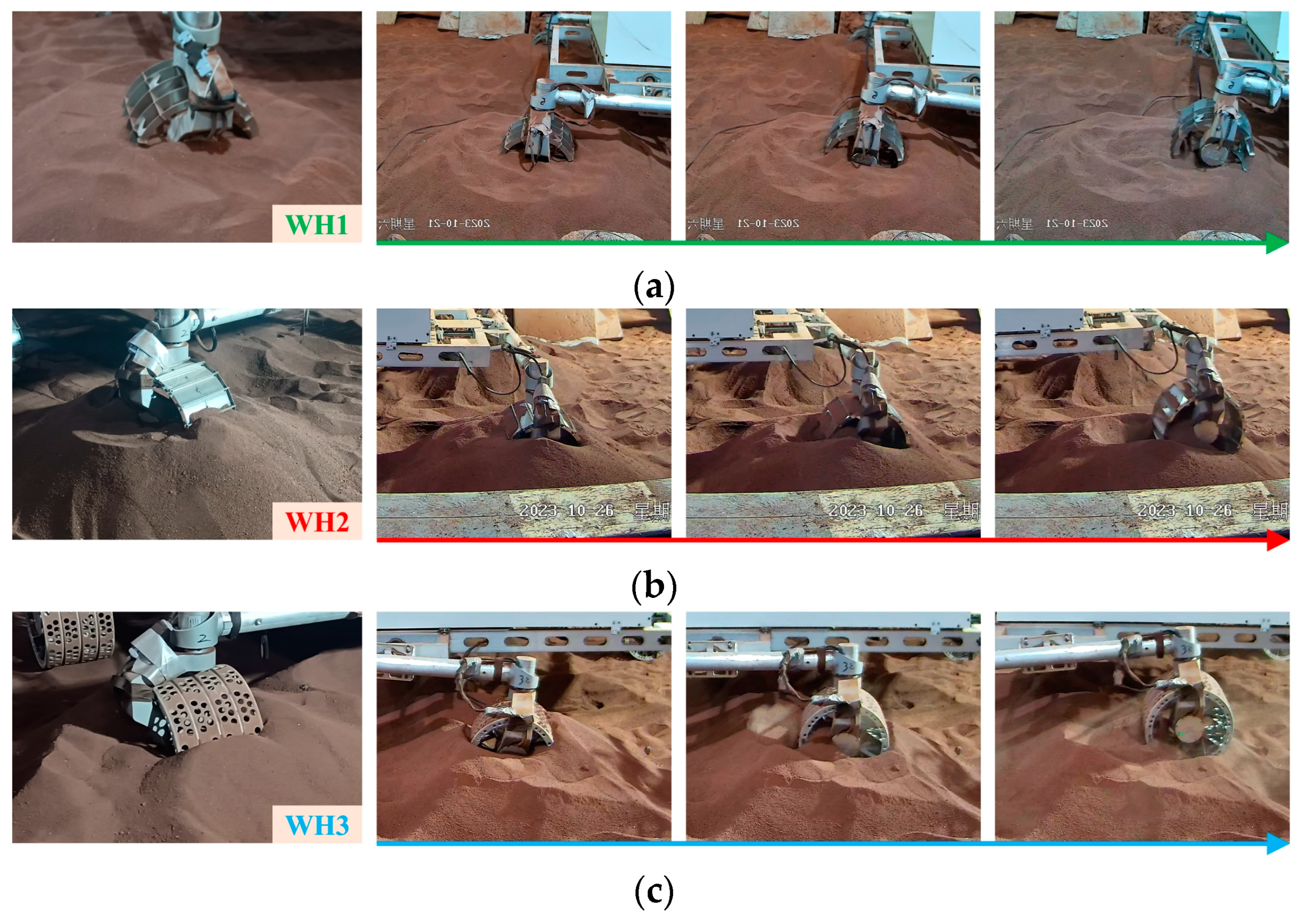
WH1 has a large slip rate on soft terrain, the slowest driving velocity on the flat road surface itself and the longest passing time under single-wheel sinkage conditions. However, as the number of sinkage wheels increases, the number of wheels that can provide additional driving force gradually decreases, and the influence of wheel characteristics on the ability to get out of sinkage gradually becomes obvious. The WH1 has a high grouser and no tread structure, which provides great advantages for getting out of deep sinkage. The wheel will be disturbed in the simulated planetary soil so that the wheel can continuously obtain the forward driving force (
Figure 12a). The wheel transfers the front soil to the rear side to reduce the difficulty of driving, and the soil gathers on both sides to provide the driving force. The number of sinkage wheels and the depth of trapped wheels will not affect the ability of the wheels to shift the soil. The wheels can obtain the driving force continuously, and the influence on the wheel passing time is not obvious.
When WH2 is out of sinkage (
Figure 12b), the simulated planetary soil between the wheel grousers will be transferred to the rear side of the wheel so that the wheel will continue to obtain a forward path. However, due to the complete closure of the tread, the closed space between the wheel grousers is certain, particles accumulate at the root of the wheel grouser, and the amount of transferable simulated planetary soil is limited, which limits the sinkage escape velocity. The wheel advances slowly in the early stage, escaping sinkage. After the wheel gradually breaks away from the deep pit, the soil at the root of the wheel grouser gradually decreases, and the speed of escaping sinkage is accelerated. WH2’s high grouser structure is highly destructive to the soil and has a good ability to pass in single-wheel and double-wheel passing environments, but the ability to pass is weaker than that of WH1.
When WH3 is out of sinkage (
Figure 12c), the rotation of WH3 causes the simulated planetary soil to be brought into the front side of the wheel through the sieve hole so that the wheel continues to obtain a forward path, but because WH3 has no wheel grouser, the damage ability to the simulated planetary soil is weak. The remaining five wheels of WH3 can provide enough driving force to push the wheels out of sinkage quickly under the condition of single-wheel sinkage. Since WH3 can only destroy the soil through the sieve holes on the tread, the disturbance ability to the soil is weak. The wheel cannot get out of the deep pit and does not have the ability to move quickly after sinkage. As the number of sunken wheels increases, the time for the wheels to get out of sinkage gradually becomes longer.
The wheel sinkage will be accompanied by high slip. When the slip rate is high, the WH1 traction coefficient is the highest, and it must have the strongest ability to get out of sinkage. With the increased slip rate, the traction coefficient of WH2 increases more than that of WH3, and the ability to get out of sinkage is better than that of WH3.
4.5. Rover Climbing Ability Test
In this test, the climbing ability of the test rover was judged by the total time of the test rover running straight on the 20° slope for 3 m (
Figure 13). On the 20° slope with a total travel of 3 m, all wheels ran smoothly. WH3 had the longest running time on the slope, with a total slip rate of 94.6%. WH2 had the shortest running time on the slope, with a total slip rate of 33.1%. WH1 took a total of 270.81 s, WH2 took a total of 89.75 s and WH3 took a total of 1105.52 s.
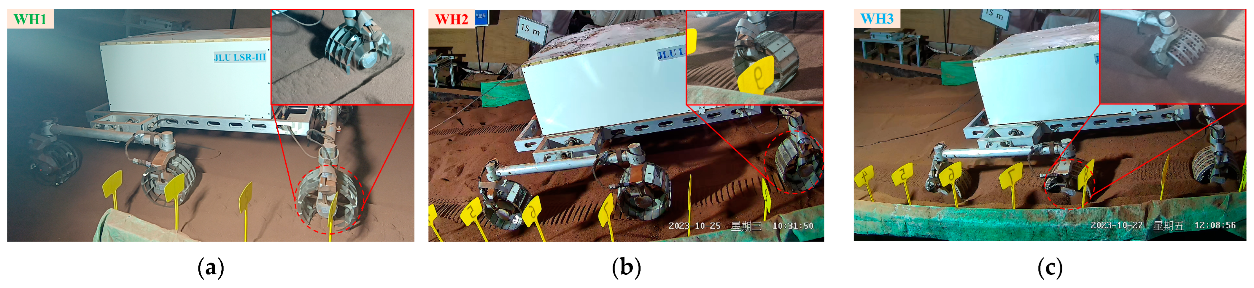
WH1 (
Figure 14a) had a high amount of sinkage during climbing and pulled back a large number of simulated planetary soil to form a square rut with WH1 characteristics, but the rut was dense and not obvious. During the climbing process of WH1, the soft medium was disturbed backward by the wheel grouser, producing a backward thrust to the soft medium and giving it a backward initial velocity. Due to the slope and gravity, the soft medium particles fall naturally below the syncline. Thus, the soft medium that WH1 can gather becomes loose, and the driving force that can be obtained is reduced, so the climbing velocity is slower than the plane. Under the condition of high slip, the traction coefficient of WH1 is higher, and the wheel grouser of WH1 continues to pull the soil so that it can continue to advance smoothly through the slope; however, the wheel has no tread structure, which makes the wheel sink too much during the climbing process, and the equivalent radius of the wheel decreases, resulting in a slower travel velocity of WH1.
WH2 (
Figure 14b) gradually slowed down during the climbing process. When WH2 climbs, the rut prints gradually become denser, the damage of the wheel grousers to the simulated planetary soil increases, the rut gap generated by the wheel grousers gradually becomes larger, and the slip rate gradually becomes larger. Because of its tread structure, WH2 has a stronger ability to aggregate soil and runs faster than WH1. However, the test used a 360 N load, and WH2 sinkage was low. If the load increases when climbing, the increased sinkage causes the accumulation of soft medium at the root of the WH2 wheel grouser, and the slip rate may increase. Because the traction coefficient of WH2 does not increase significantly with the slip rate, the climbing ability of WH2 may decrease.
After WH3 (
Figure 14c) began to go uphill, the wheels began to sink gradually, and the amount of sinkage gradually increased. The wheel formed a rut higher than the slope, and the rut print no longer had hole characteristics; the rut print was a dense strip. WH3 has no wheel grouser structure, which is mainly through friction when climbing in a soft medium, so the velocity is slow. Under the current load, the slip rate of WH3 on the slope was more than 90%, the amount of sinkage exceeded the radius of the wheel and the ability of WH3 to get out of sinkage was poor. If the climbing load is increased, there may be a phenomenon where the wheel is deep and unable to climb, which is not suitable for driving on the slope.
4.6. Summary
WH1 has high wheel grousers without tread, and there may be slippage when crossing obstacles, which takes a long time. However, it has a very high advantage in the deep sinkage. It can pass smoothly under climbing conditions, but the velocity is slow. WH2 has high grousers, and it may slip when crossing obstacles, but it has a tread structure to avoid slippage as much as possible. In the deep environment, it can successfully move out of sinkage, but in the whole deep environment round, escape from sinkage ability is not good; thus, it has a very high advantage in climbing environments. WH3 is a sieve tread without a wheel grouser structure, and the obstacle crossing velocity is the fastest. However, the ability to get out of sinkage and climb are poor.
In summary, the wheel tread structure will make it possible for the wheel to slip when crossing the obstacle, and the tread structure can reduce the slip time. For the escape environment, the wheel’s grouser and the tread non-closed rate have a higher improvement effect on the wheel’s escape ability. For the climbing environment, the wheel grouser and the tread closure rate can improve the climbing ability.
5. Conclusions
This paper explores the performance parameters of three different wheels and their trafficability on soft terrain. WH1 has a high wheel grouser on both sides of the rim and no tread; WH2 has higher rims on both sides of the wheel and a closed tread; WH3 has a non-wheel barbed mesh tread. The sinkage, slip rate and traction coefficient of the wheel are measured by performance parameter tests. WH1 has the characteristics of high sinkage and high slip. When the slip rate is low, the traction coefficient is low, but the traction coefficient is obviously improved with the increased slip rate. WH2 has a higher sinkage and slip rate, and the traction coefficient increases with the increase in slip rate, but it is not significant. The sinkage and slip rates of WH3 are the lowest, and the traction coefficient changes little with the slip rate; the traction coefficient is not high.
The rover tests on three different terrains (obstacle crossing, out of sinkage and climbing) were carried out. The test results show that each wheel can pass smoothly on soft terrain, but due to the different driving modes of each wheel, the passing capacity is different. WH1 may slip when crossing obstacles, which takes a relatively long time, but it has a very high advantage in the deep environment; it can pass smoothly under climbing conditions, but the velocity is slow. WH2 may slip when crossing obstacles, but it can avoid slips as much as possible with its tread structure. In the deep environment, it can be successfully moved out of sinkage, but in the whole deep environment round, its out-of-trouble ability was not good. However, it has a very high advantage in climbing environments. WH3 has the fastest obstacle crossing velocity; however, the ability to remove difficulties and climb is poor, so it is not suitable for application in climbing environments.
Based on the performance test and terrain test, the grouser structure will reduce the equivalent radius of the wheel, increase the sinkage of the wheel, and disturb the soil while driving to increase the slip rate and the traction coefficient of the wheel. The tread structure can avoid excessive sinkage and slip rate, but it also reduces the traction coefficient of the wheel under higher slip rates. The sieve tread has the ability to destroy the soil to obtain the driving force under the soft terrain, and the traction coefficient is slightly increased with the slip rate. The wheel grouser structure allows the wheel to slip when crossing the obstacle, and the tread structure can reduce the slip time. For the out-of-sinkage environment, the wheel grouser and tread non-closure rate of the wheel have a higher improvement effect on the wheel’s out-of-sinkage ability. For the climbing environment, the wheel grouser and tread closure rate can improve the climbing ability.
For unmanned detection in outer space environments with high-reliability requirements, it is necessary for wheels to have reliable passing ability in various terrains. Although the grouserless structure can drive quickly on conventional soft terrain and has a good obstacle-surmounting ability, it does not have the ability to cope with emergencies (climbing, getting out of sinkage) and is not suitable for use on soft terrain. Non-tread wheels can better adapt to extreme conditions, but the equivalent radius is small, and the efficiency is too low. According to the test results, the advantages of the three kinds of wheels can be integrated, and the locally closed tread (with hole tread) and the two-side edge-sealed grouser wheel can be designed so that it can not only have a high soil accumulation effect but also does not limit the backward flow of soil to ensure better passing ability and higher driving efficiency under the conditions of obstacle crossing, out of sinkage and climbing.


