1. Introduction
In the field of aircraft design and development, achieving dynamic stability within the flight envelope is both challenging and expensive. For transonic flight, particularly, the interaction between shock wave induced separation, swirling motion, and flow rupture generates complex, unsteady, and nonlinear fluid dynamics. These interactions often result in aerodynamic effects that exceed simple expectations, sometimes leading to unexpected and significant outcomes. During the aircraft design phase, predicting the limits of dynamic operational stability and the intensity of potential dynamic issues is arduous, with many issues only becoming apparent during the flight testing stage. This fact directly results in an extended aircraft design cycle, a substantial increase in design costs, and negative impacts on overall performance.
The significance of these challenges becomes particularly pronounced for fighter aircraft, which demand exceptional maneuverability and operability at a high angle of attack (AoA), as well as for tailless stealth aircraft, which are prone to exhibiting unsteady dynamic behaviors. For traditional aircraft operating at relatively low speeds and small AoA, static stability derivatives are adequate to estimate the moments produced during maneuvers [
1]. However, at higher AoA, nonlinear aerodynamic effects such as boundary layer separation, vortex oscillation, and vortex breakdown are inevitable. Moreover, these phenomena are particularly important in transonic or supersonic flow regimes, where the formation of shock waves is more likely to occur [
2].
Developing improved flight models requires an aerodynamic framework with precise dynamic derivatives, particularly for high-AoA flight regimes, where these parameters play a crucial role in influencing flight performance [
3]. Dynamic derivative information has traditionally been obtained through flight tests, although these are often expensive and carry significant risk [
4]. An alternative method that has been extensively utilized involves using wind tunnel experimental data to determine dynamic stability derivatives [
5]. However, the wind tunnel testing approach, while valuable, has notable limitations and can become expensive due to the complexity of experimental setups required to replicate various dynamic motions. Furthermore, it is crucial in the experiments to remove the inertial forces generated by the oscillating test model from the aerodynamic data in order to ensure accurate measurements. Achieving this result requires precise synchronization between the motion history and the recorded moment data. Even a minor mismatch in synchronization can introduce significant errors in dynamic derivative calculations, necessitating an exceptionally accurate and meticulously designed experimental setup. Additionally, scaling challenges and support interference issues present further complications in wind tunnel testing. These challenges are particularly pronounced at high AoAs and for high Mach number conditions, where they impede accurate predictions of the model’s aerodynamic characteristics. Another critical limitation arises from delays in measurement data due to the mechanical nature of the vibration devices, which can introduce errors. These factors collectively highlight some of the primary constraints associated with wind tunnel testing [
6,
7].
On the other side, recent advancements in computational power and technology have made it possible to analyze dynamic stability derivatives using applied computational fluid dynamics (CFD) methods, addressing the above-mentioned limitations. Specifically, progress in computational capacity, along with innovations in moving grid techniques, like dynamic meshing, enables the high-dimensional study of more intricate flight vehicle models. Practically, these advancements strengthen the efficiency and accuracy of numerical analysis for evaluating dynamic stability derivatives [
7,
8]. A significant portion of recent research in this field focuses on developing efficient approaches to calculate combined dynamic stability derivatives, especially concerning pitch damping coefficients.
The concept of stability in aerodynamic derivatives within the linear range of small disturbances was initially proposed by Bryan [
9], who suggested that aerodynamics and flight dynamics can be considered separately, allowing the aerodynamic forces and moments to be expressed as functions of various static and dynamic factors, such as disturbance velocities, control angles, and their rates of change. Early analytical approaches were applied to simple two-dimensional configurations, such as Theodorsen’s method for analyzing wing sections [
10]. This approach has since been refined to better identify directional and sideslip derivatives, for instance, for flow around a thin airfoil at supersonic speed [
11].
Additionally, time domain techniques can be utilized to assess dynamic stability derivatives by solving the unsteady flow field and its associated time-dependent parameters, often utilizing a forced oscillation method [
12]. The method involves inducing oscillations in an aircraft model around its center of gravity, maintaining a constant angular displacement magnitude. In this context, one of the straightforward displacement techniques available is the simple harmonic oscillation (SHO) method. This approach involves inducing oscillations with simple harmonic motion. By doing so, the unsteady aerodynamic forces, computed using CFD tools, can be applied to determine the dynamic stability derivatives [
13]. However, these computations are particularly challenging due to the complexity of the unsteady flow field to be reproduced. Traditional calculation methods typically include fast engineering calculations [
14], linear frequency domain methods [
15], nonlinear frequency domain methods [
16], and high-precision time domain predictions [
6]. While these methods provide simplified approximations of time domain CFD calculations, they are not well suited for capturing the nonlinear behavior of complex configurations. Indeed, accurate unsteady simulations require accounting for the significant role of viscosity effects within the internal flow field. Complex flows arise from shock wave–boundary layer interactions, and flow nonlinearity is highly apparent. Given the limited prior knowledge on the dynamic simulation of internal flows, time domain accurate prediction, representing the most advanced level of nonlinear aerodynamic behavior prediction, emerges as the optimal choice for dynamic unsteady calculations.
In this complex scenario, the Reynolds-averaged Navier–Stokes (RANS) equations can be employed to simulate the unsteady flow field for vehicle simple harmonic vibrations, studying the aerodynamic behavior under oscillatory motions. The unsteady RANS approach, supplied with the proper closure turbulence model, has been often utilized for dynamic stability analysis in aerospace industry, e.g., [
17,
18,
19]. Here, the forced SHO approach is applied for the transonic flow regime, with the NASA Common Research Model (CRM) serving as the base geometry. Three different oscillation modes (pitching, rolling, and yawing) are designed to isolate specific dynamic stability derivatives by applying harmonic motion around the corresponding principal axis. The CFD setup employs a dynamic meshing technique, with user-defined functions (UDFs) controlling the harmonic motion inputs to simulate the oscillatory behavior of the aircraft model.
The objective of this study is to demonstrate the effectiveness of the forced SHO method in calculating dynamic stability derivatives under complex flow conditions. This approach is significant compared to traditional methodologies because it allows for more accurate capturing of the nonlinear behavior of the aerodynamic flow field, particularly in the transonic regime, where shock waves and boundary layer interactions are prevalent. Additionally, using CFD for dynamic stability derivative estimation offers a cost-effective and safer alternative to wind tunnel and flight tests, which are often expensive and risky. This method also enables precise synchronization between motion history and recorded moment data, reducing errors in dynamic derivative calculations, and enhancing the reliability of the results. The present research focuses on the estimation of dynamic stability parameters using transient CFD within the transonic regime and at high AoAs. The current analysis aims to provide valuable insights into the longitudinal and lateral-directional responses of the aircraft model, contributing to a deeper understanding of its dynamic behavior under complex flow conditions.
The remainder of this paper is organized as follows.
Section 2 provides an overview of the methodology employed, detailing the implementation of forced harmonic oscillations and the computational framework used to extract dynamic stability derivatives. In
Section 3, the complete applied CFD model is presented, including the description of the simplified geometry, the mesh generation process, and the simulation setup.
Section 4 discusses the results and analysis, covering the validation of the CFD model, the evaluation of aerodynamics characteristics, and the analysis of dynamic stability derivatives for different oscillatory motions.
Section 5 offers some concluding remarks.
2. Methodology
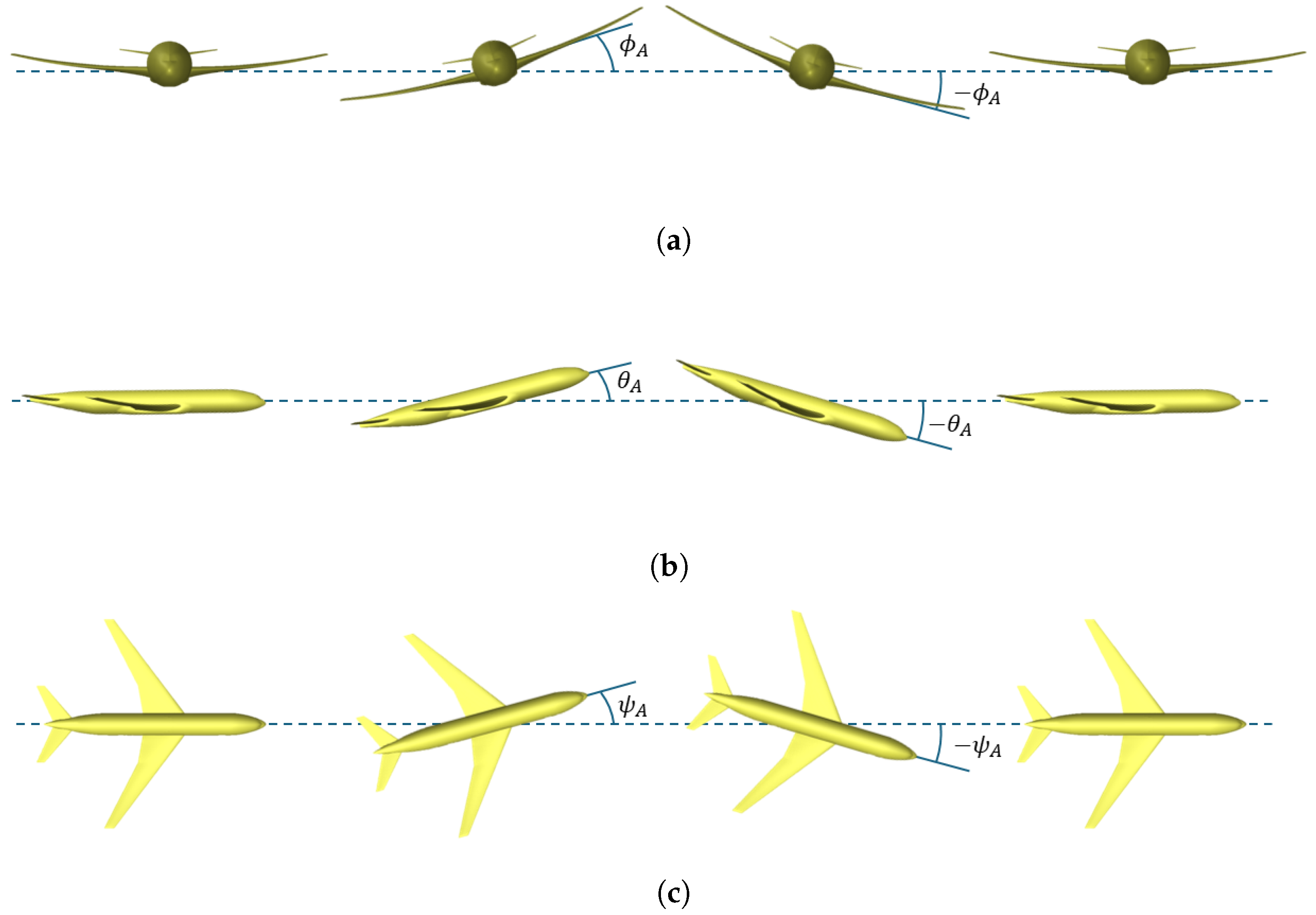
This study employs the forced SHO method to investigate unsteady aerodynamic characteristics through controlled periodic motions. Specifically, three types of simple harmonic oscillation are considered: rolling, pitching, and yawing. The rotation axes are corresponding to the three principal axes of rotation, namely, the longitudinal
X axis, lateral
Y axis, and vertical
Z axis. By conducting simulations of these basic oscillations, the corresponding unsteady aerodynamic responses can be systematically analyzed, allowing for the independent extraction of dynamic stability derivatives for each primal axis. These parameters play a crucial role in characterizing the stability and control behavior of the aircraft, as the dynamics of flight vehicles depend on the structure’s reaction to the time-varying aerodynamic forces and moments. Importantly, current oscillations at controllable frequencies provide a systematic and reproducible approach for analyzing aerodynamic responses.
Figure 1 visually represents the three different modes of simple harmonic motions employed, with
,
, and
representing the associated varying angular positions, namely, the pitch, roll, and yaw angles.
2.1. CFD Implementation
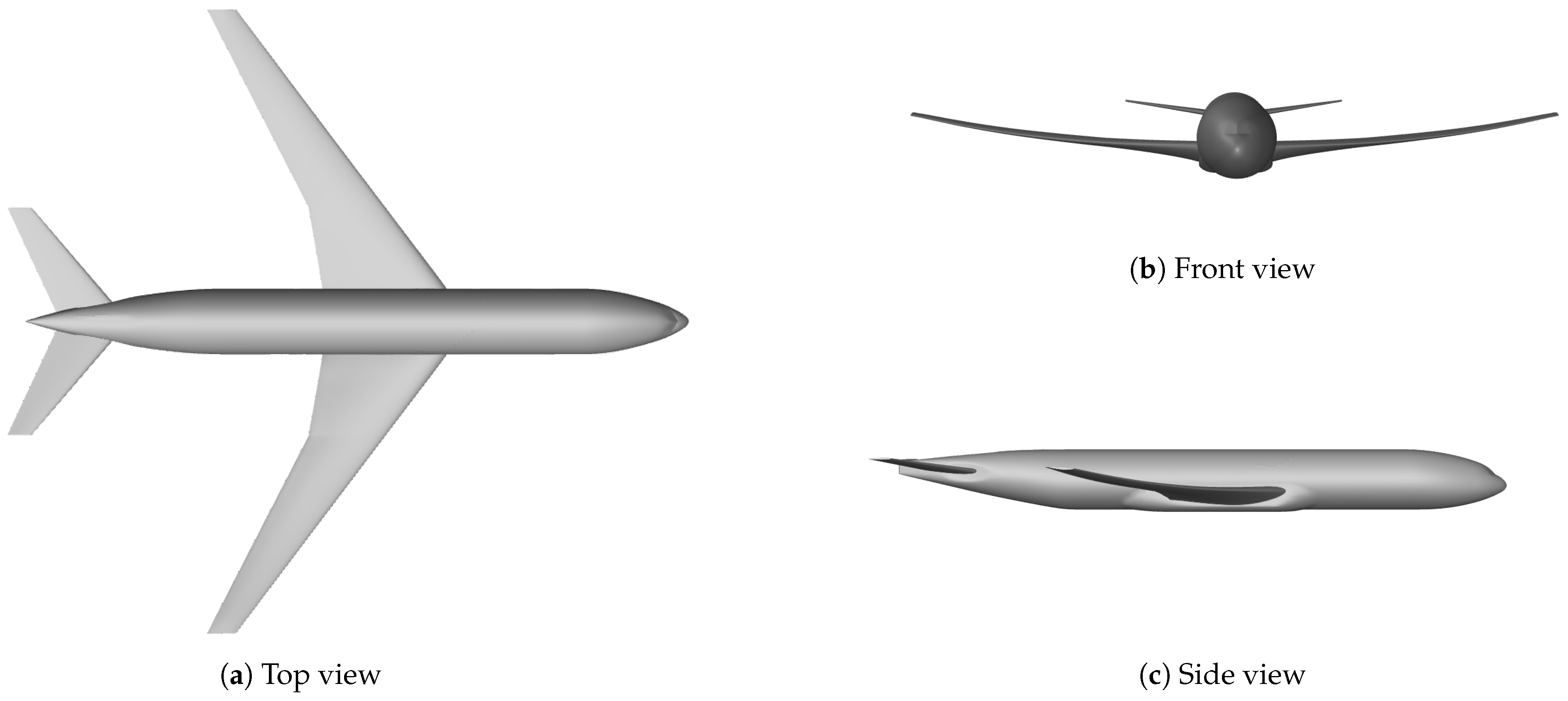
The three different harmonic motions are implemented into the applied CFD model through UDF procedures written in C programming language. These ad hoc functions are tailored to the different oscillation modes associated with the reference system depicted in
Figure 2. Each UDF procedure precisely controls the corresponding oscillation parameters (amplitude, frequency, and phase), ensuring the accurate representation of the prescribed motion of the aircraft model. Basically, each UDF defines the angular velocity for each simple mode, without imposing any translational motion, thus allowing for the pure rotation around the longitudinal, lateral, or vertical axis, as required for the stability analysis. This procedure ensures that the motion remains purely angular and does not interfere with translational velocity components in the system. The three different oscillations are shown in
Table 1, where
,
, and
represent the rolling, pitching, and yawing amplitudes, respectively, while
stands for the constant angular velocity. Specifically, the pitching motion captures longitudinal stability characteristics, the rolling motion addresses lateral stability, and the yawing motion evaluates directional stability.
To accommodate the above oscillatory motions in the current numerical simulations, a moving dynamic mesh approach is employed. The dynamic mesh is updated at each time step, using smoothing and remeshing algorithms, to maintain mesh quality and prevent element distortion during oscillations. The use of a dynamically adjusted mesh for the ongoing simulations is crucial to maintain the quality of the computations, as the deformation of the geometry during the motion must be accurately reflected by the numerical grid. This approach ensures a comprehensive assessment of the unsteady aerodynamic response for the three primary axes of motion.
2.2. Evaluation of Dynamic Stability Derivatives
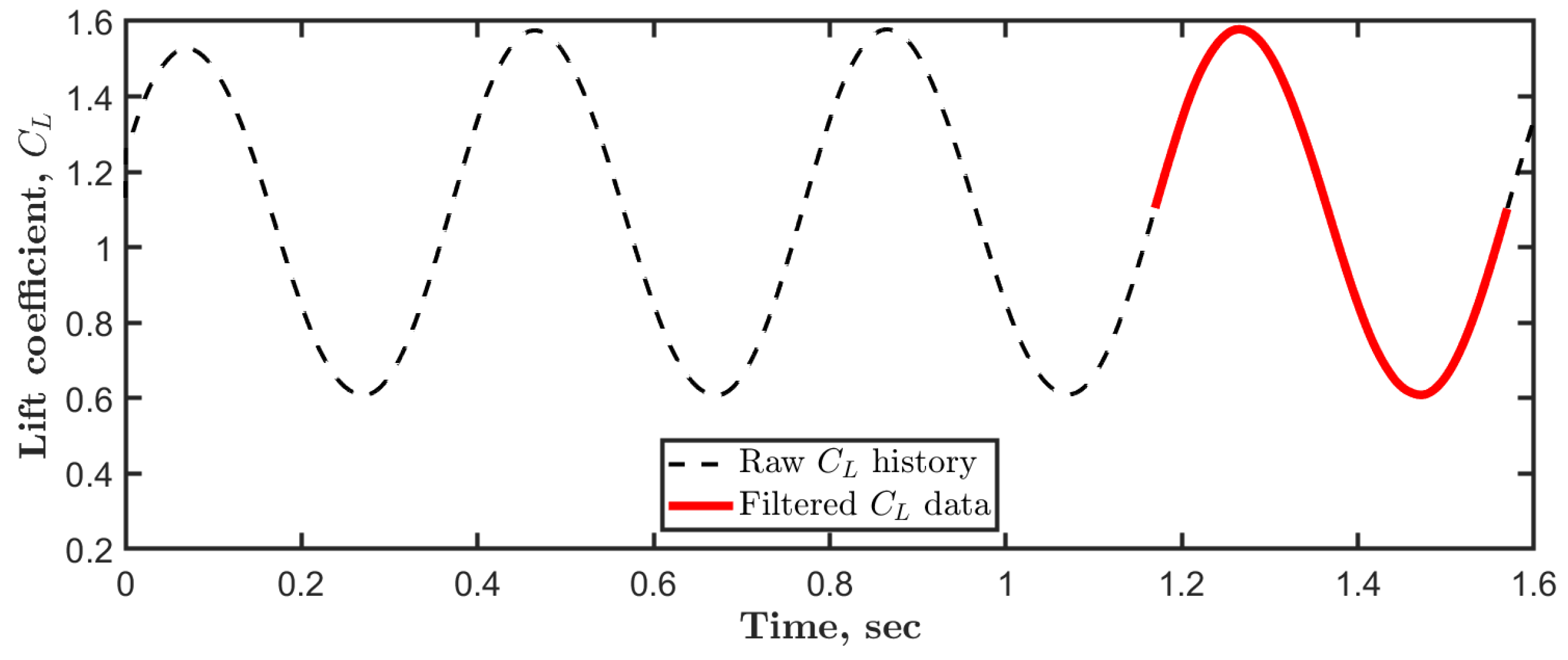
The raw data collected during the simulations include a wide range of unsteady aerodynamic forces and moments generated by the motion around each principal axis. These records capture the oscillatory response of aircraft aerodynamic performance to the prescribed harmonic motions. In order to filter the results, the initial cycles are excluded, and attention is focused on the last oscillation cycle. This filtering step is carried out to eliminate data from the initial transient phase, which would provide not yet fully converged behavior. Then, the aerodynamic data are analyzed to extract the dynamic stability derivatives by relating the aerodynamic coefficients to their corresponding kinematic inputs, such as angular displacements and angular rates. Basically, the dynamic stability derivatives can be determined by evaluating the slopes and trends in the aerodynamic coefficients relative to the imposed simple oscillations.
Following a commonly used procedure for the prediction of stability derivatives for complex configurations, the generic aerodynamic coefficient can be expressed as
, where (
) are the rolling, pitching, and yawing rates, respectively. In this way, the linear approximation for the coefficient variation reads as has been defined in, e.g., [
20]:
with
representing the initial AoA. By imposing a rolling SHO (around the
X axis), the above expression becomes
where the derivatives are denoted as
,
, and
. Analogously, for a pitching SHO (around the
Y axis), one has
while, for a yawing SHO (around the
Z axis), one has
In the present study, the above expressions were actually written for the aerodynamic coefficients
,
, and
, associated with the moment components illustrated in
Figure 2. The direct and cross derivatives that appear in the corresponding Equations (
2)–(
4) are summarized in
Table 2. Notably, beside the normal coefficients,
,
, and
, as well as the cross derivatives,
and
, the other dynamic stability parameters consist of coupled terms representing the simultaneous dependence on both oscillation rates and time rates of change of corresponding angular positions.
The evaluation of the various dynamic stability derivatives can be attained by exploiting the unsteady numerical data provided by the CFD simulations. The practical procedure leads to the solution of a least squares problem, where the dependent variables are the integrated aerodynamic coefficients, while the independent arguments are the instantaneous oscillation angles and their rates of change [
6]. The interested reader is referred to the cited references for a detailed description of the method.
5. Conclusions
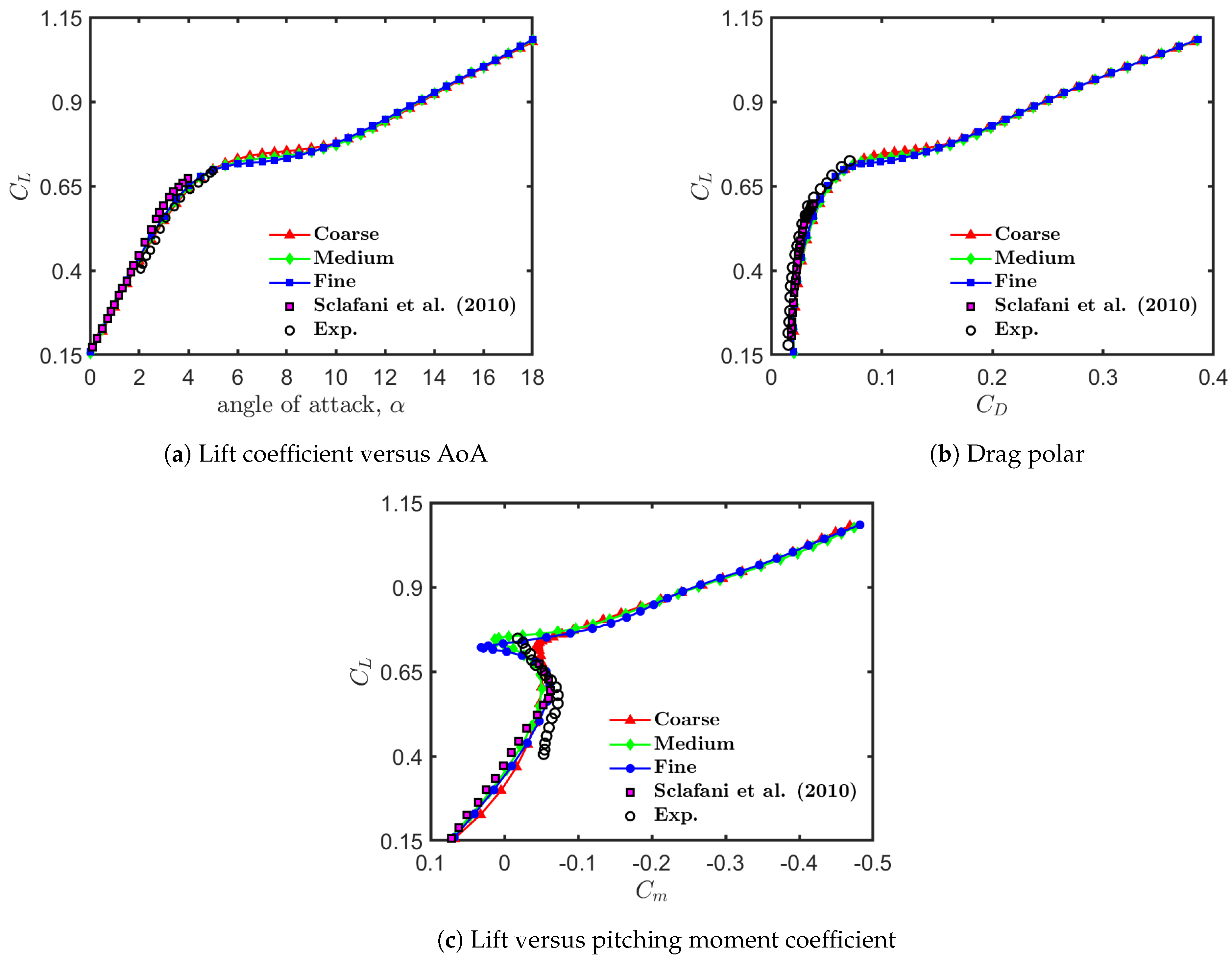
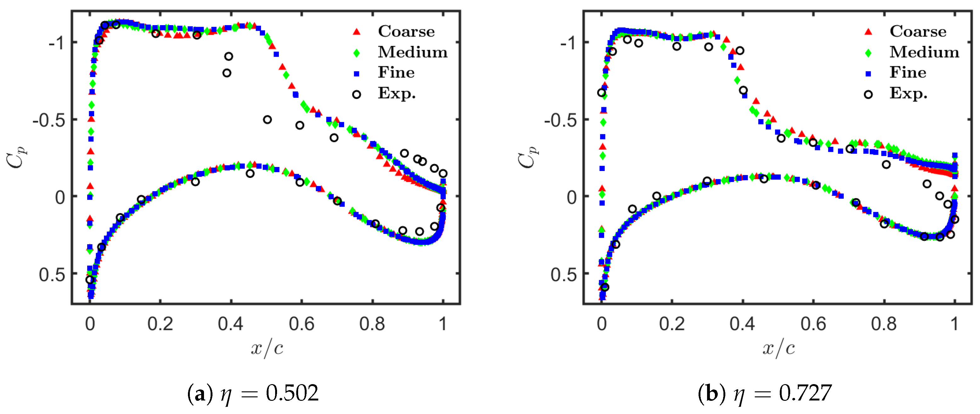
The work conducted in this study aimed to investigate the use of transient CFD simulations for evaluating the dynamic stability derivatives of commercial aircraft at feasible computational costs. Using the NASA common research model as a test case, the various computations demonstrated the effectiveness of the forced simple harmonic oscillation method in predicting dynamic derivatives across the various axes of motion (pitch, roll, and yaw). The results were obtained for a Reynolds number of and a Mach number of for flight conditions that are representative of the transonic regime. As a proof of concept, dynamic stability derivatives were numerically evaluated and analyzed for two different flight conditions, corresponding to two different initial angles of attack.
A key finding of the present study was the effectiveness of dynamic meshing techniques in providing an accurate representation of unsteady aerodynamic behavior while maintaining computational efficiency. The unsteady aerodynamic coefficients allowed for a detailed evaluation of the longitudinal and lateral-directional stability of the aircraft, with particular attention to the complex effects introduced by compressible flow separations and shock-boundary layer interactions. Moreover, the current results confirmed that CFD-based forced oscillation methods can serve as a valuable alternative to traditional wind tunnel testing, providing greater flexibility in parametric studies and eliminating constraints related to test stand limitations [
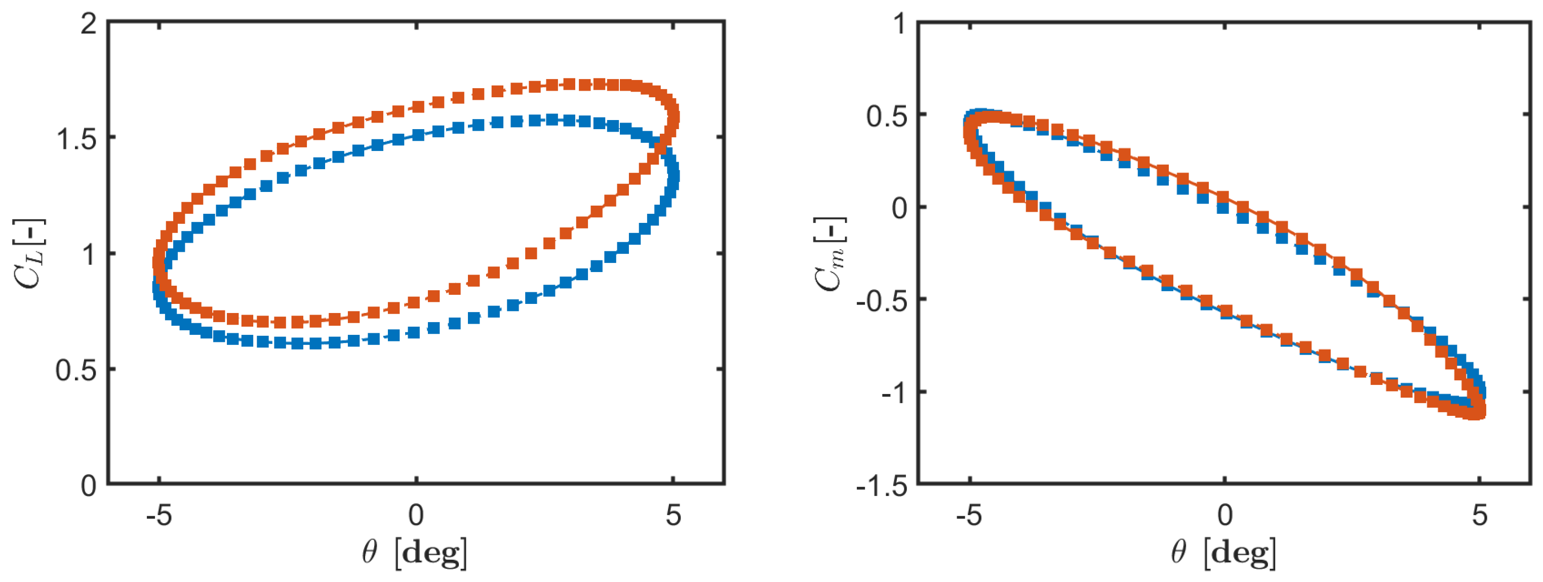
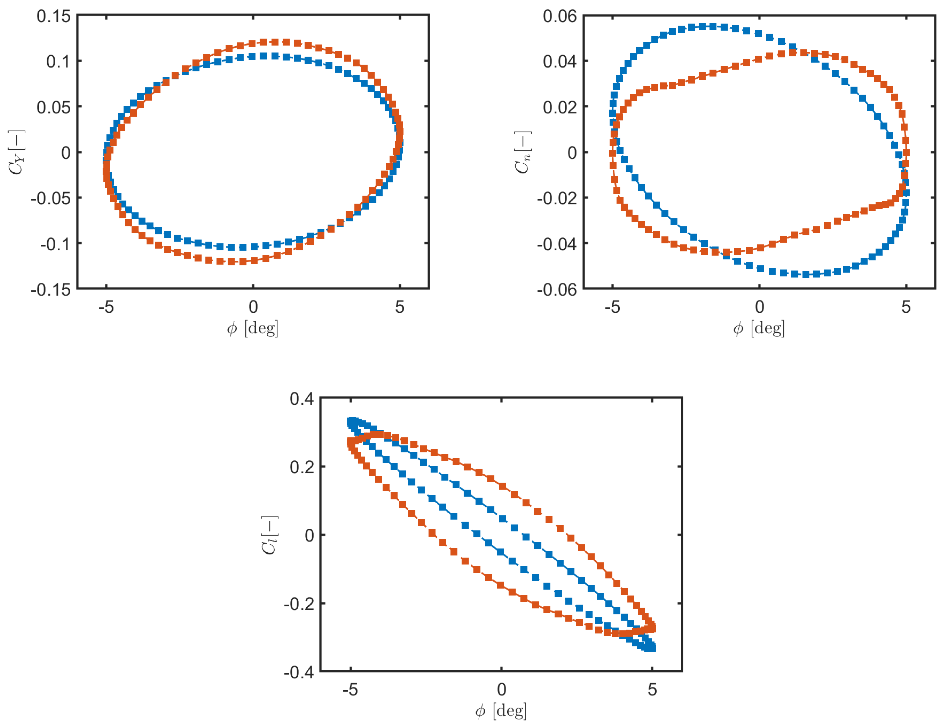
6,
7]. The observed hysteresis effects in aerodynamic coefficient plots, particularly in the transonic regime, further underscore the importance of capturing nonlinear unsteady flow features, which are difficult to isolate in experimental setups. Moreover, this study demonstrated that the numerical approach aligns well with theoretical stability trends, reinforcing the reliability of CFD for stability derivative estimation. These findings suggest that CFD-based methods can be systematically integrated into early-stage aircraft design to refine aerodynamic performance predictions before physical testing, reducing development time and cost [
1].
Overall, this study provided new insights into the dynamic behavior of the aircraft model in unsteady flow conditions, opening the path for future developments that could further improve aerodynamic design and flight performance simulation, particularly in transonic and supersonic regimes. In fact, while the present results are very promising, this study also highlighted areas for potential improvement. Specifically, to enhance the accuracy of the CFD simulations, future work will integrate higher-fidelity turbulence models, such as hybrid RANS-LES methods, which combine Reynolds-averaged Navier–Stokes (RANS) and large-eddy simulation (LES) approaches to better capture complex flow phenomena, as suggested by recent research findings, e.g., [
36,
37]. In addition, extending the current methodology to maneuvers involving coupled oscillations could provide deeper insights into cross-coupling aerodynamic effects, further testing the predictive capability of applied CFD models for aircraft stability analysis. Indeed, the scope of the research could be also expanded to more complex geometries, including engine nacelles and control surfaces, to better represent real-world flight conditions.


 ) and (
 ).
).

