1. Introduction
A stratospheric airship is an aircraft that relies on atmospheric buoyancy to achieve long-term station-keeping in the air, offering broad application prospects in fields such as ground observation, communication relay, and high-altitude reconnaissance [
1,
2]. Lightweight and high-strength envelope materials are critical to the development of stratospheric airships as they directly determine the airship’s load-bearing capacity and service life [
3]. The complexity of the service environment of stratospheric airships demands that envelope materials possess both high strength and low weight.
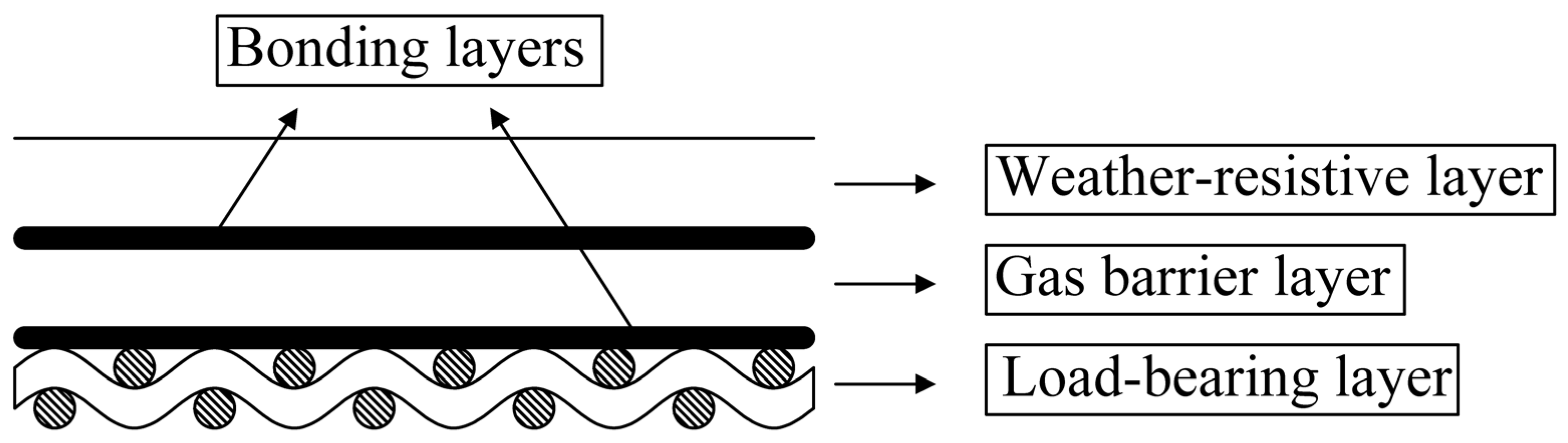
Currently, typical envelope materials for stratospheric airships are composed of load-bearing layers, gas barrier layers, and weather-resistive layers, which are laminated and bonded together as
Figure 1 shows [
4]. The load-bearing layer, which serves as the primary structural component, is woven from high-strength, lightweight synthetic fibers such as Vectran and poly(
p-phenylene benzobisoxazole) (PBO) [
3]. The gas barrier layer typically employs materials with low helium permeability, such as polyurethane and polyvinyl chloride [
5]. The weather-resistive layer, designed to protect against environmental factors like ultraviolet radiation, ozone erosion, and thermal radiation, often uses materials such as polyurethane (PU) and polyvinyl fluoride (PVF) [
4]. The load-bearing layer is generally woven from warp and weft yarns, with common weaving patterns including plain weave and 2 × 2 twill weave. Due to its unique microstructure and manufacturing process, the mechanical properties of the envelope material exhibit significant nonlinearity and orthotropy. As a flexible material, the envelope material has negligible bending stiffness and cannot withstand compressive loads. Furthermore, the interaction between the load-bearing layer and the other layers (gas barrier layer, weather-resistive layer, and adhesive) also influences the mechanical properties of the envelope material [
6,
7]. These unique characteristics complicate the analysis of the material’s mechanical properties and the selection of appropriate strength criteria [
8].
Previous theoretical and experimental studies have demonstrated that the applicability of strength criteria depends on the material type, stress state, and failure mode [
8,
9]. Under actual working conditions, envelope materials are often subjected to biaxial stress, and their failure strength is typically significantly lower than that under uniaxial conditions [
10]. For instance, biaxial tensile tests on polyurethane-coated UHMWPE fabrics revealed a 30–40% reduction in strength compared to uniaxial cases, attributed to stress concentrations at fiber–matrix interfaces [
11]. However, in structural design, the design strength of envelope materials is frequently determined based on their uniaxial tensile strength, with a large safety factor applied [
12]. This approach stems from the complexity and diversity of failure modes in envelope materials, as well as the influence of external environmental factors on their mechanical properties [
13]. Recent studies highlight that hygrothermal aging can further reduce the biaxial strength of silicone–elastomer composites by up to 25%, due to hydrolysis-induced interfacial degradation [
14]. Additionally, in situ X-ray tomography has enabled direct observation of crack initiation in laminated envelopes under multiaxial loads, revealing that micro-void coalescence dominates failure initiation in cyclic loading regimes [
15]. Therefore, accurately determining the load-bearing limit state of envelope materials and clarifying their failure mechanisms are of great significance for guiding engineering practice.
Failure is one of the simplest yet most critical mechanical behaviors of envelope materials [
16]. This study focuses on analyzing the fracture failure behavior of these materials and proposing a strength criterion that accurately reflects their mechanical response. First, uniaxial tensile tests are conducted on the envelope material at various off-axial angles to determine its failure strength. Next, the failure mechanism is investigated through a combination of finite element simulations and macroscopic fracture morphology analysis. Finally, several commonly used strength criteria are compared with the experimental results, and a new strength criterion is proposed to achieve better agreement with the test results.
2. Materials and Methods
The test material is a type of stratospheric airship envelope material with a thickness of 0.21 mm and a surface density of 140 g/m2. It is composed of three layers laminated together: an outer functional layer, a load-bearing layer, and an inner functional layer. The load-bearing layer is woven from Vectran fibers in a plain weave pattern.
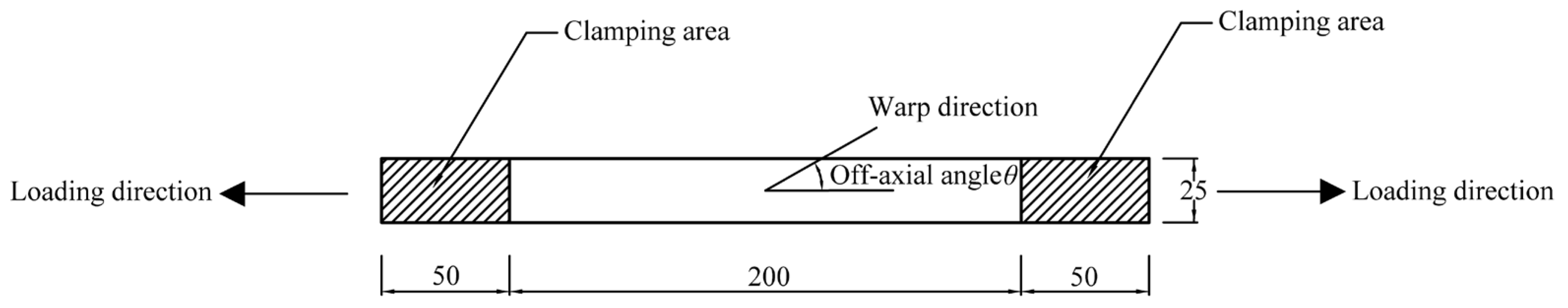
The uniaxial tensile test specimen is illustrated in
Figure 2. The specimen has a total length of 300 mm, with an effective testing region length of 200 mm and clamping areas of 50 mm at both ends. The width of the specimen is 25 mm. The off-axial angle for uniaxial tensile testing is defined as the angle between the loading direction and the warp fibers of the specimen. Specifically, off-axial angles of 0° and 90° correspond to loading directions aligned with the warp and weft fibers, respectively.
The uniaxial tensile test specimens are divided into seven groups, with off-axial angles of 0°, 15°, 30°, 45°, 60°, 75°, and 90°. Five tests are conducted for each off-axial angle to ensure statistical reliability.
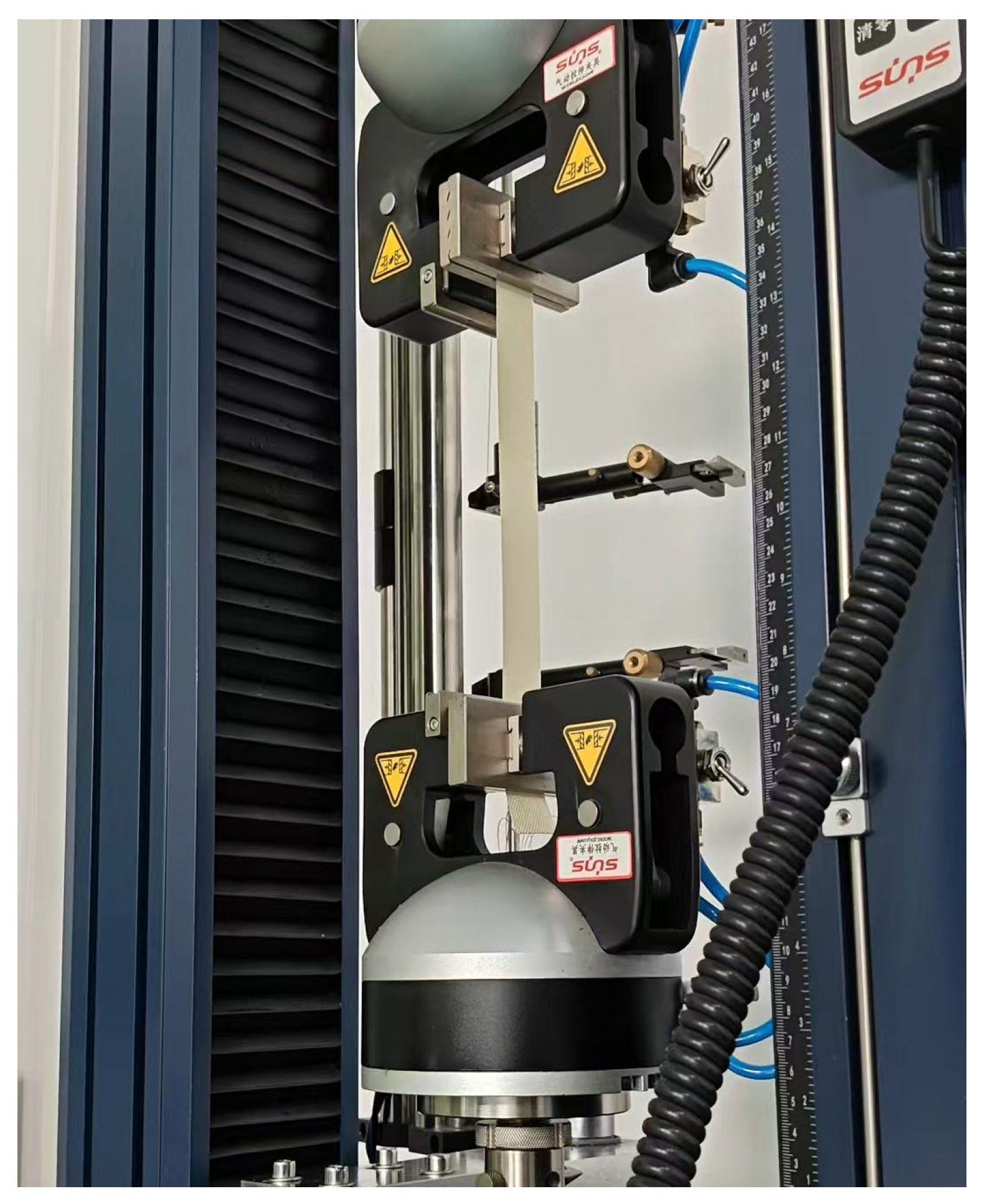
The uniaxial tensile tests were performed using a UTM6503 electronic testing machine (Sunthink Science and Technology Development Corporation, Shenzhen, China). This testing machine has a maximum load capacity of 5 kN, a displacement measurement range of 10–800 mm, and a displacement resolution of 0.008 mm. The tests were conducted under displacement-controlled loading at a rate of 0.5 mm/s. Loading was continued until specimen failure, and the maximum load-bearing capacity of the specimen during the loading process was recorded.
Figure 3 shows the typical appearance of the machine and the specimen.
3. Results and Discussions
Table 1 shows the failure strength data of the specimens under off-axial tensile conditions as well as the statistical data. It should be noted that the data were obtained from five repeated tests for each group, with coefficients of variation (CV) ranging from 0.05 to 0.11. The limited number of replicates may introduce epistemic uncertainties in the statistical estimates. While the observed CV values indicate moderate data dispersion, the small sample size could affect the reliability of further analyses.
The failure morphologies of specimens under different off-axial angles are shown in
Figure 4.
0°: Fracture surfaces are perpendicular to the loading direction with smooth profiles. Unbroken yarns distribute symmetrically along the specimen’s central axis. Pure tensile failure occurred;
30°: Specimens exhibit asymmetric fracture morphology, characterized by localized rupture on one side with exposed yarn ends and residual unbroken yarns on the opposite side. This tension–shear mixed-mode failure is evidenced by non-planar fracture surfaces and a combination of fiber breakage and matrix shear cracking;
45°: Specimens demonstrate complete yarn severance across the cross-section, with 45°-inclined fracture surfaces and significant necking deformation at rupture zones. This pure shear failure mechanism is confirmed by the uniform distribution of shear bands and the absence of tensile fiber fractures.
Biaxial loading more accurately represents the actual stress conditions experienced by the envelope material of stratospheric airships compared to uniaxial loading [
17]. The orthotropic mechanical properties of the envelope material arise from its plain weave structure. In the local coordinate system of the material, its two-dimensional orthotropic elastic constitutive relationship can be expressed as follows [
18]:
where
and
are the normal stress in weft and warp directions,
and
are the Young’s moduli in weft and warp directions,
and
are the normal strain in weft and warp directions,
is the shear stress,
is the shear modulus,
is the shear strain,
and
are the Poisson’s ratios in warp and weft directions. Since the uniaxial tensile properties in the warp and weft directions of the material are similar, it is assumed that the Poisson’s ratios in these directions are equal, denoted as:
Therefore, Equation (1) can be simplified as:
For biaxial tensile tests, which are generally conducted with a fixed ratio of stresses in the warp and weft directions, assume the stress ratio
(
and not both 0), then we have [
19], which is as follows:
When
or
, the biaxial loading condition of the material transforms into a uniaxial loading condition. The stress–strain relationship then simplifies to the following:
Therefore, by determining the slope of the material’s uniaxial tensile stress–strain curve, we can use it as the elastic modulus during the tensile process to assess whether the material’s mechanical properties exhibit significant linear characteristics.
The stress–strain curves and their corresponding slopes for the envelope material under uniaxial tensile loading in the warp and weft directions are shown in
Figure 5. The failure strengths of the material in the warp and weft directions are similar. Although the slopes of the stress–strain curves exhibit some fluctuations, they remain relatively stable within the range of 5000 MPa to 9000 MPa. The mechanical properties of the material demonstrate strong linear characteristics, indicating that the behavior in the warp and weft directions is nearly identical. This similarity is attributed to the mechanical properties of the yarns constituting the load-bearing layer and the plain weave pattern of the material [
20].
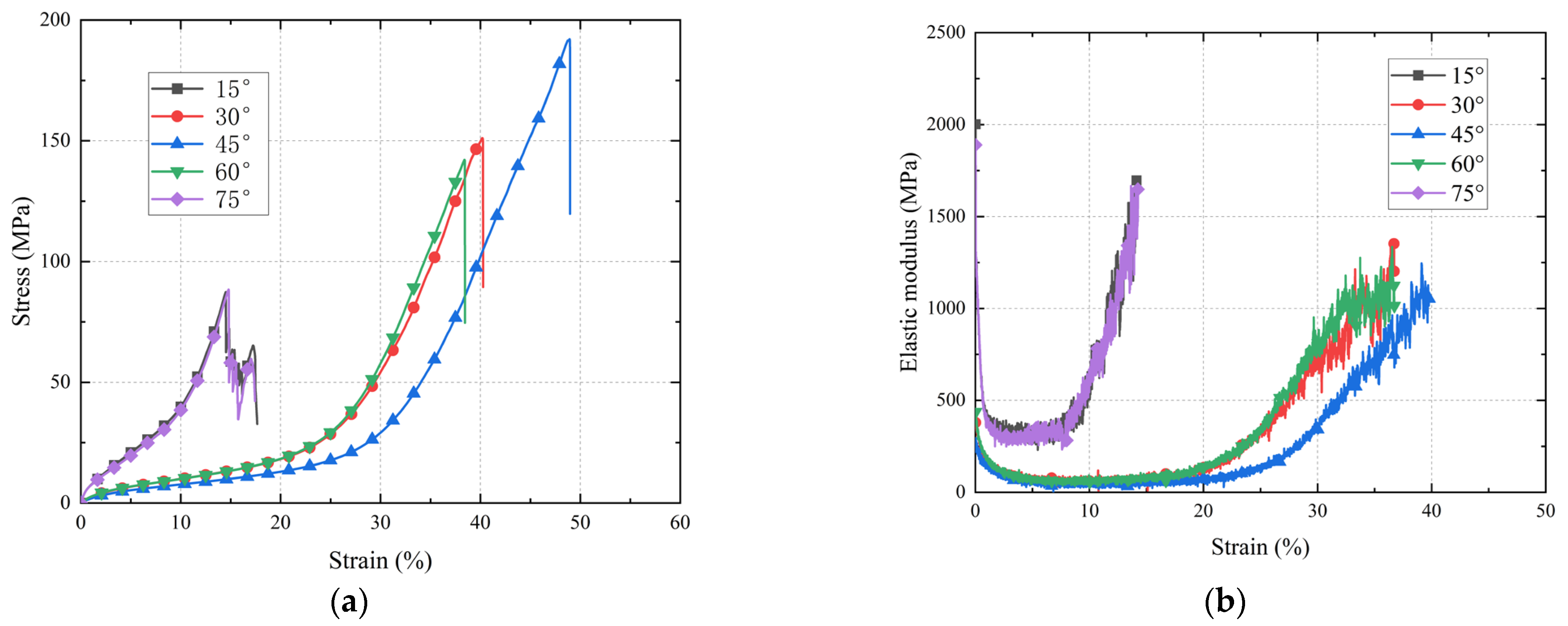
The uniaxial tension curves of the material at off-axial angles exhibit distinct characteristics compared to those in the warp and weft directions. As shown in
Figure 6, the stress–strain curves for 15° and 75°, as well as 30° and 60°, display striking similarity. This suggests that the mechanical properties of the material at off-axial angles are symmetric about the 45° axis. Under off-axial loading conditions, the maximum strain of the material increases significantly, while its load-bearing capacity decreases markedly. During the initial tensile loading phase, the stress–strain curve has a steep slope, which then rapidly diminishes and stabilizes at a lower level. This stage is accompanied by substantial material deformation. Once the strain exceeds a critical threshold, the slope of the stress–strain curve gradually increases until the material reaches its failure point.
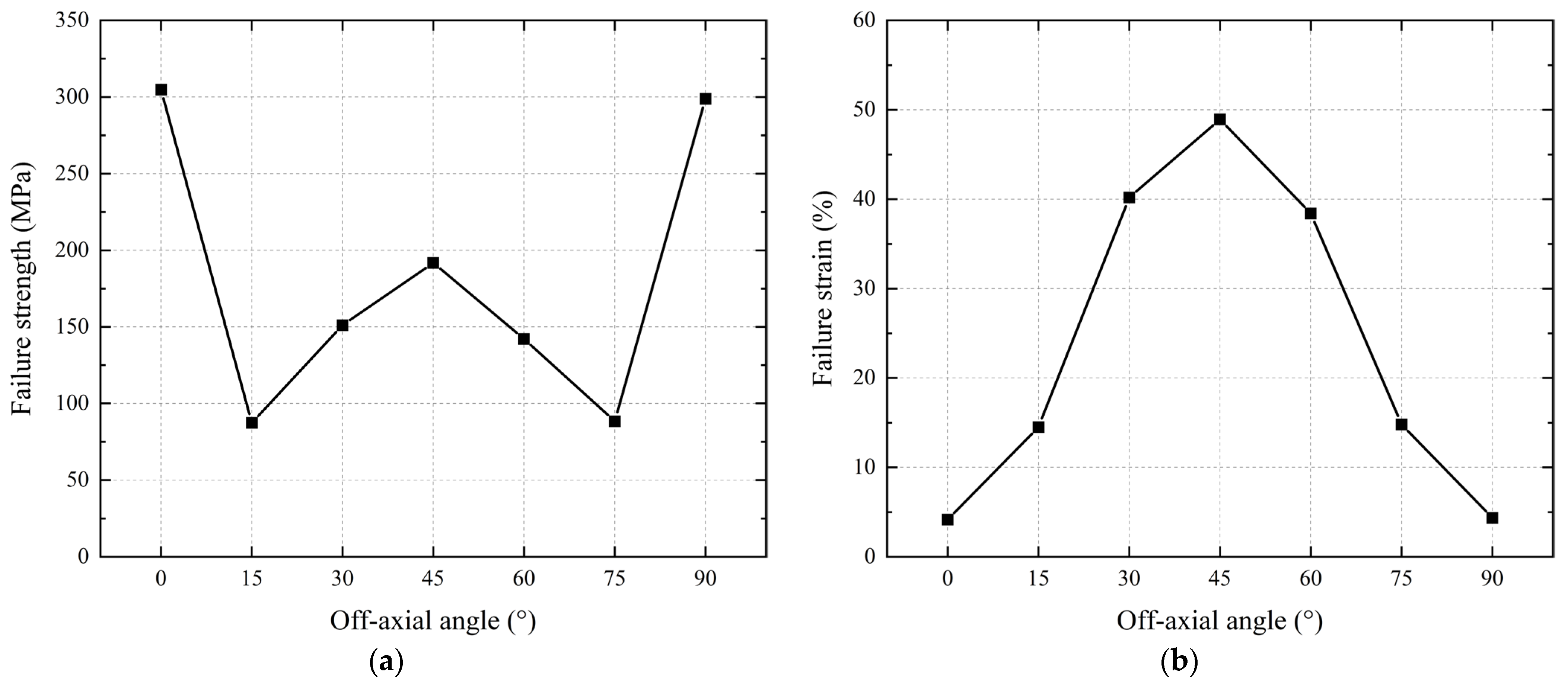
The failure strengths and strains of the material at various off-axial angles are illustrated in
Figure 7. The failure strength of the envelope material exhibits a distinct “W” pattern across the 0–90° range as the off-axial angle increases. At small off-axial angles (15° and 75°), the failure strength decreases sharply compared to the warp and weft directions. As the angle increases further, the failure strength gradually rises, peaking locally at 45°. However, the specific off-axial angle corresponding to the minimum failure strength cannot be definitively identified due to dependencies on factors such as fiber strength, weaving density, fiber crimp, and the bonding strength between the load-bearing and functional layers [
21,
22]. In contrast, the failure strain increases proportionally with the off-axial angle, reaching its maximum value at 45°.
4. Analysis of Failure Modes and Mechanisms
The stress–strain curves and macroscopic fracture morphologies of uniaxial tensile test specimens vary significantly with off-axial angles. Tensile tests in the warp and weft directions exhibit similar behavior, with specimens fracturing at the central position. In these cases, the yarns are severed simultaneously along the direction perpendicular to the tensile stress axis, indicating pure tensile failure. The material demonstrates its highest failure strength and lowest failure strain under uniaxial tensile loading in the warp and weft directions. During these tests, the specimens show negligible lateral contraction, and delamination between the load-bearing layer and the functional layers of the envelope material is confined to localized areas near the fracture site. The material’s mechanical properties exhibit strong linear characteristics, aligning with the mechanical behavior of Vectran fibers [
23].
At off-axial angles of 15°, 30°, 45°, 60°, and 75°, the tensile test specimens display fracture patterns distinct from those observed in the warp and weft directions. Unlike the centrally fractured warp/weft specimens, the fracture location in off-axial tests shifts closer to the clamping region, accompanied by pronounced lateral contraction in the specimen’s midsection. The introduction of shear stress causes fibers in the load-bearing layer to fail sequentially rather than simultaneously. Compared to warp/weft uniaxial tensile tests, specimens tested at off-axial angles exhibit a significant increase in maximum strain and a marked reduction in failure strength. These results highlight pronounced nonlinear mechanical behavior of the envelope material.
Finite element simulations of the tensile tests at 15°, 30°, and 45° were conducted using Abaqus v. 2019. The model employed S4R quadrilateral shell elements, with the material defined as an orthotropic lamina. The mass density of the material was set to 1.4 g/cm³. The warp and weft elastic moduli were derived from experimental uniaxial tensile test data, while the shear modulus was determined using the method introduced in
Section 5 and was set to 99.4 MPa. Vectran fiber, a polyarylate-class material, typically exhibits a Poisson’s ratio in the range of 0.2–0.3 for monofilament forms [
24]. However, the Poisson’s ratio of woven fabrics generally exceeds that of individual fibers due to their interlaced architecture, which permits greater transverse deformation under loading [
25]. After consulting the material manufacturer and reviewing structural characterization data, the Poisson’s ratio of the composite system has been conservatively set to 0.4 in this paper. Off-axial loading conditions were simulated by rotating the material’s orthotropic coordinate system. Regarding the boundary conditions, all translational degrees of freedom except the loading direction and all three rotational degrees of freedom were constrained. The specimen was subjected to a fixed boundary condition, and a prescribed displacement load was applied at one end. The simulation results are shown in
Figure 8 and
Figure 9.
In off-axial tensile tests, the angular misalignment between fiber orientation and loading direction causes primary load-bearing fibers to deflect under load. As the angular relationship between warp and weft fibers evolves, the material experiences combined tensile–shear stresses. The ultimate failure mode is strongly influenced by the specimen’s off-axial angle. Fibers in the load-bearing layer are subjected to two distinct loading regimes:
Continuously spanning fibers anchored at both clamps primarily endure tensile stress.
Discontinuous fibers (with at least one free end) experience partial tensile stress and shear stress transmitted from the functional layer.
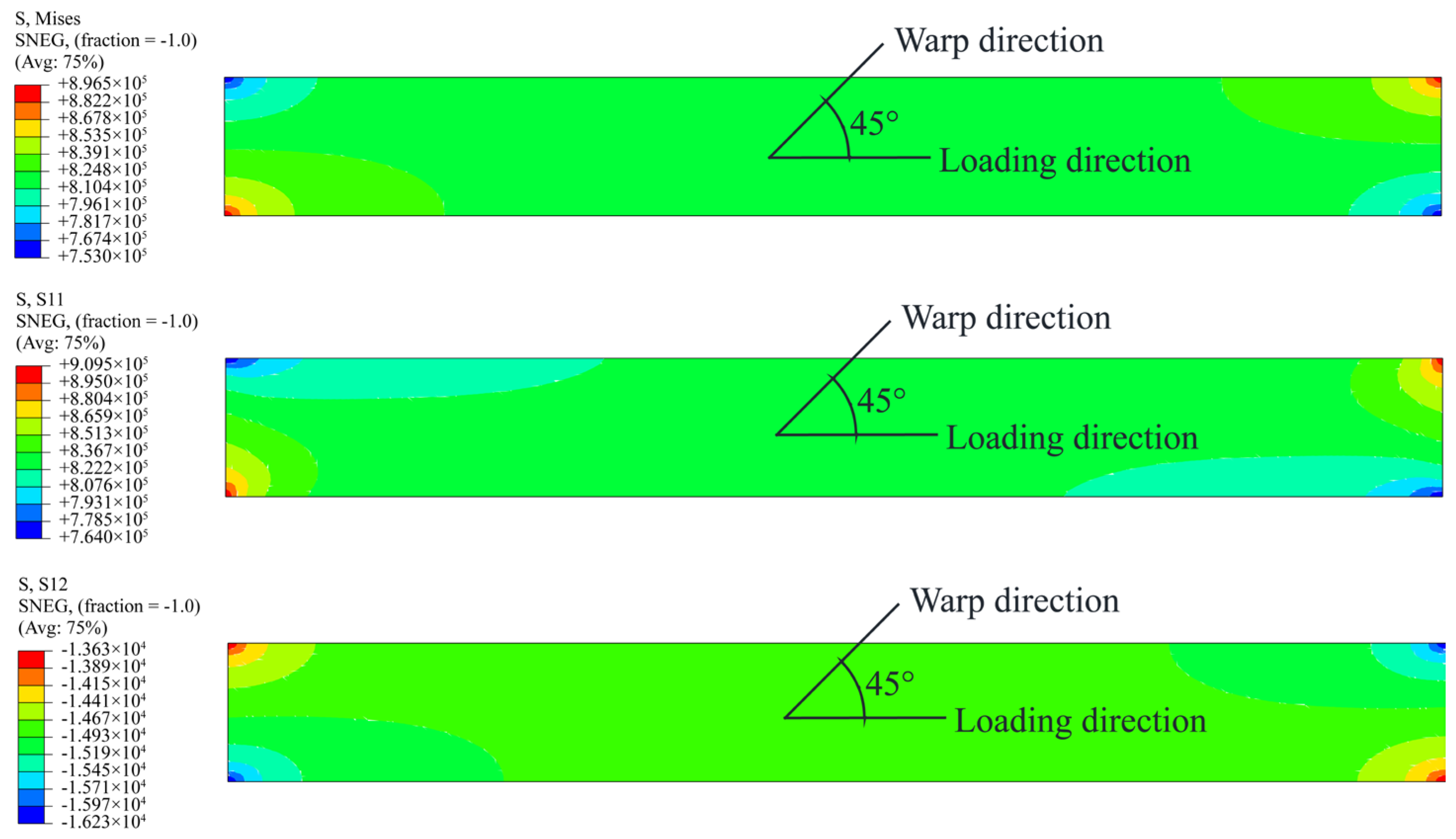
Under small off-axial angles, edge fibers—unable to span the specimen’s full length—exhibit drastically reduced tensile capacity. As shown in
Figure 8, the stress concentration boundary at the specimen’s edge aligns with the off-axial angle direction. While tensile stress remains dominant here, the rapid rise in shear stress at fiber edges induces delamination from adjacent fibers and the functional layer [
26]. This tension–shear coupling precipitates the sharp decline in failure strength observed in small off-axial angle specimens compared to warp/weft cases [
27].
As the off-axial angle increases, fibers attempt to reorient toward the loading axis but are constrained by interlayer adhesion. Edge fibers shorten further, and shear stress increasingly governs fracture behavior. During this transition, failure shifts from tension-dominated to a hybrid tensile–shear mode.
At 45°, the minimal number of tensile-loaded fibers—symmetrically distributed—causes failure to initiate at the specimen’s edges, where interlayer constraints are weakest. Shear stress dominates entirely, culminating in pure shear failure. This configuration maximizes deformation while increasing failure strength relative to smaller off-axial angles.
Based on the stress transformation matrix in composite mechanics, the stress components in the local coordinate system of off-axis tensile loading can be expressed as:
where
and
are the normal stress and shear stress in the local coordinate system, respectively.
According to Equation (6), as the off-axial angle increases, the term exhibits a pronounced rise, driving a nonlinear increase in shear stress. The essence of the tensile–shear coupling effect lies in the synergistic interaction between these two stress components.
Furthermore,
Figure 8 and
Figure 9 clearly demonstrate that under off-axial tensile loading, pronounced stress concentrations develop at the corners of the specimen clamping areas. This phenomenon leads to fracture initiation near the clamping areas and promotes progressive yarn failure from one side to the other, rather than simultaneous rupture across the specimen width. These observations are mechanistically consistent with the failure morphologies depicted in
Figure 4.
5. Strength Criteria
Strength criteria are fundamental to composite material mechanics. A growing number of these criteria are applied to composites, with their predictive accuracy and theoretical maturity continuing to improve [
28,
29,
30]. For stratospheric airship envelope materials, stresses in the thickness direction are typically negligible, allowing the material’s stress state to be simplified to a plane stress condition.
The Tsai–Wu criterion, grounded in strength tensor theory, offers versatile applicability. While it achieves high predictive accuracy by accounting for compressive strength, its complex formulation [
31] and reliance on compressive parameters render it unsuitable for envelope materials, which inherently lack compressive load-bearing capacity [
32]. Similarly, the Hoffman criterion [
33] faces the same limitation.
Several strength criteria better suited for envelope material analysis include: the Tsai–Hill criterion, the Yeh–Stratton criterion, and the Norris criterion [
9,
21,
34].
The Tsai–Hill criterion is as follows:
The Yeh–Stratton criterion is as follows:
The Norris criterion is as follows:
where
and
are the tensile strength in weft and warp directions, and
is the shear strength.
The shear strength can be calculated using the method described in reference [
35].
As shown in
Figure 10, the yarns of the plain weave are deformed under the action of the diagonal load. The shear tensile strength of the specimen
can be expressed as follows [
36]:
where
is the load applied in the diagonal direction and
is the side length.
Based on the failure mechanism of off-axial tensile tests, the failure that occurs at 45° is classified as pure shear failure, which is consistent with the shear tensile failure described in the model. Therefore, the off-axial tensile strength at 45° can be converted to the diagonal load
in the model as follows:
where
is the angle between the warp and weft directions, which can be taken as 90° in this paper;
is the tensile failure strength at 45° off-axial angle; the coefficient
is a reduction factor that converts
to
along the diagonal direction when shear failure occurs. The value of
typically ranges from 0.7 to 0.8 [
30].
Combining two Equations above, the shear strength when the material undergoes pure shear failure can be determined as follows:
It is observed that the Equations for the Tsai–Hill criterion and the Norris criterion are very similar. In this paper, the failure strengths in the warp and weft directions of the material are very close. Therefore, the predicted failure stress values from the Tsai–Hill criterion and the Norris criterion are very similar. As a result, the Norris criterion will not be considered further in the analysis.
Figure 11 presents a comparison between the results of the off-axial tensile tests and the predictions of two existing strength criteria.
Both the Tsai–Hill and Yeh–Stratton criteria utilize experimental uniaxial tensile test results from the warp and weft directions as theoretical strength values in those orientations. The Tsai–Hill criterion further incorporates experimental data from the 45° off-axial tensile condition into its predictions. However, significant discrepancies arise between the predictions of these criteria and experimental results at the remaining four test angles. Notably, both criteria fail to capture the marked reduction in material strength observed at small off-axial angles.
To address these limitations, a modified strength criterion is proposed for the plain-woven envelope material tested in this study. This new criterion introduces interaction terms between the warp, weft, and shear stresses. The criterion can be described as follows:
where
,
, and
are parameters obtained from test results [
30].
is the interaction factor between the warp and weft directions, while
and
are the interaction factors between the warp/weft directions and shear stress, respectively. Since the tensile strengths in the warp and weft directions of the material studied in this paper are similar,
and
are also close in value.
Based on the transformation matrix between on-axial and off-axial coordinate systems in composite mechanics, the material’s failure strength can be resolved into warp direction, weft direction, and shear stress components. Given that
X,
Y, and
S have been determined through prior experimental and computational work, substituting the off-axial tensile test results into Equation (13) transforms it into a governing Equation containing the interaction terms
F12,
F16, and
F26. For instance, when
F16 =
F26 = 19.96 and
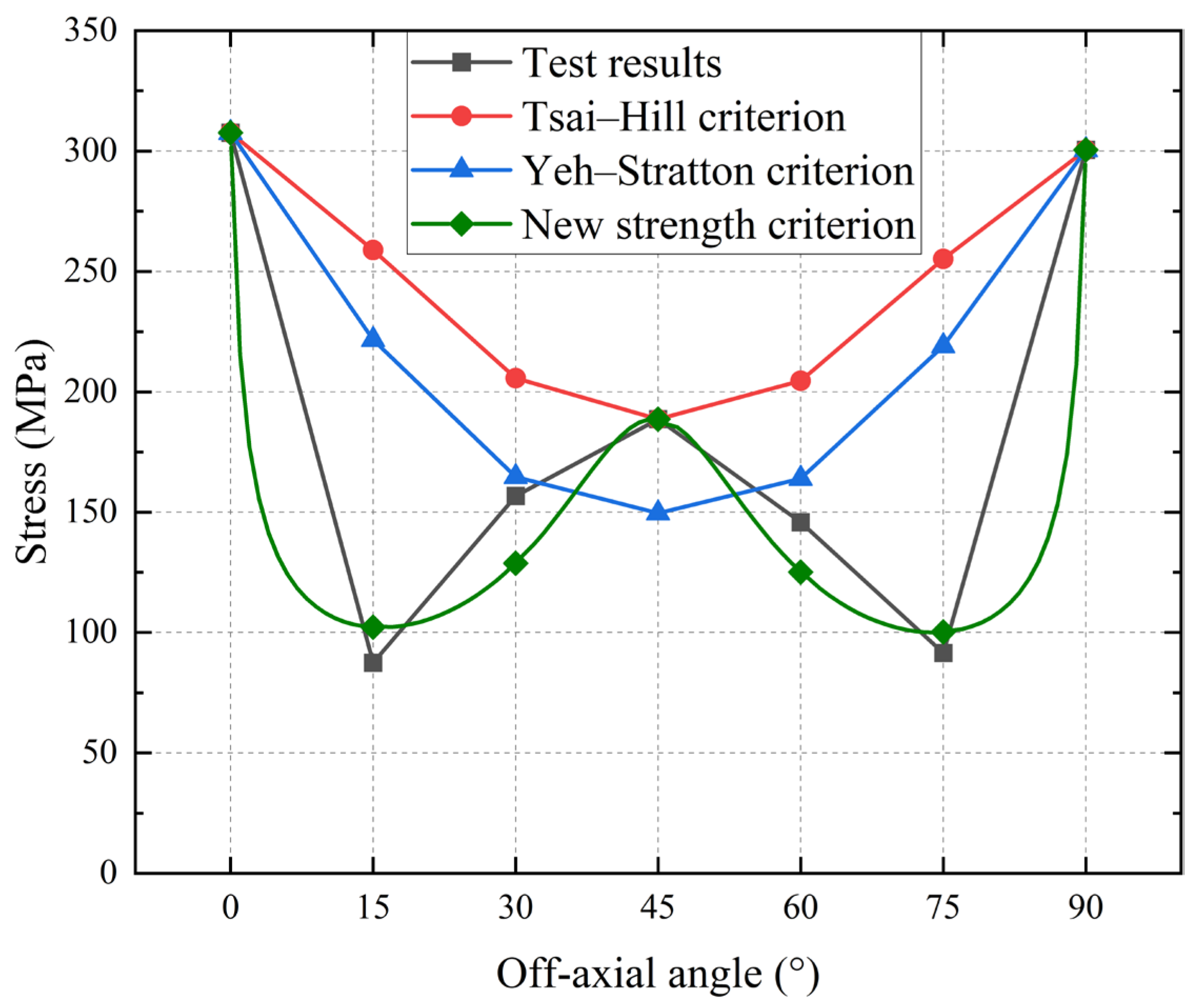
F12 = −123.1, the comparison of the prediction of the off-axial tensile strength of the material using the new strength criterion with other existing strength criteria is shown in
Figure 12 and
Table 2.
It should be noted that the parameter values specified above have not been optimized to minimize the difference between predicted values and test results. If sufficient off-axial tensile test data are available, the determination of parameters is transformed into an optimization problem for solving overdetermined systems of Equations, typically addressed via least-squares minimization. Compared to the other two existing strength criteria, the new strength criterion aligns more closely with the test results. Furthermore, it is capable of accurately describing the sharp decrease in material strength at small off-axial angles.
6. Conclusions
This study investigates the uniaxial tensile behavior of stratospheric airship envelope materials under varying off-axial loading conditions. Through systematic off-axial tensile testing, we analyze specimen failure mechanisms, evaluate the accuracy of existing strength criteria, and propose a modified criterion to address observed limitations.
The envelope material exhibits orthotropic behavior, with mechanical properties approximately symmetric about the 45° axis. As the off-axial angle increases, failure strength follows a “W”-shaped trend (decreasing initially before rising), while failure strain increases monotonically, peaking at 45°. Material strength is governed by parameters such as fiber strength, weaving density, fiber crimp, and interlayer adhesion between the load-bearing and functional layers.
Three distinct failure modes emerge:
Pure tensile failure in warp/weft directions, where fibers rupture under normal stress, yielding maximum strength.
Mixed tensile–shear failure at intermediate angles (15–75°), where discontinuous fibers partially disbond and slip under combined stresses, drastically reducing strength.
Pure shear failure at 45°, characterized by edge-initiated fiber debonding and maximum strain due to shear dominance.
Existing strength criteria (e.g., Tsai–Hill, Yeh–Stratton) show poor agreement with experimental data, particularly at small off-axial angles (15–30°). This discrepancy likely stems from inadequate representation of stress interactions (warp–weft–shear coupling). To address this, we propose a modified Tsai–Hill-based criterion incorporating explicit stress interaction terms. Validation demonstrates superior predictive accuracy for off-axial failure strength compared to conventional models, offering enhanced reliability for airship envelope design. Woven composite materials are extensively utilized in airship structural systems. The methodology proposed in this study demonstrates generalizability to other plain weave materials, provided that their orthotropic symmetry and fiber–matrix compatibility align with the fundamental assumptions. Crucially, the predictive accuracy of the new strength criterion hinges on the precise calibration of three parameters.
This study still has several limitations that warrant further investigation. The following improvements are recommended to enhance the scientific rigor and engineering relevance:
The off-axis angles should be subdivided more granularly, particularly within the 0–15° range. This would allow clearer observation of how the progressive reduction in the number of clamped yarns at both ends correlates with the decline in material failure strength as the off-axis angle increases.
- 2.
Experimental validation of shear strength:
The current shear strength value is derived through empirical estimation with inherent uncertainties due to the inclusion of a reduction coefficient in the calculation. Direct measurement of shear strength would provide ground-truth data to improve the accuracy of the proposed failure criterion.
- 3.
Biaxial tensile testing for engineering fidelity:
Given that airship envelope materials predominantly experience biaxial loading in warp/weft directions during service, subsequent work should implement biaxial tensile experiments. This would enable development of safety factors aligned with operational envelopes.


