Review

Mechanics of Space Debris Removal: A Review

by
Mohammad Bigdeli
1,2,
Rajat Srivastava
1,2 and
Michele Scaraggi
1,2,3,*
1
Department of Engineering for Innovation, University of Salento, 73100 Lecce, Italy
2
Center for Biomolecular Nanotechnologies, Istituto Italiano di Tecnologia, Arnesano, 73010 Lecce, Italy
3
Department of Mechanical Engineering, Imperial College of London, London SW7 2AZ, UK
*
Author to whom correspondence should be addressed.
Aerospace 2025, 12(4), 277; https://doi.org/10.3390/aerospace12040277
Submission received: 10 February 2025 / Revised: 14 March 2025 / Accepted: 19 March 2025 / Published: 26 March 2025
(This article belongs to the Section Astronautics & Space Science)

Abstract

:
The growing population of space debris poses a critical risk to space operations, requiring urgent removal strategies. Numerous scientific investigations have focused on debris capture mechanisms in Earth’s orbits, including contact and contact-less capturing methods. However, the known debris population exhibits a multiscale distribution with broad statistics concerning size, shape, etc., making any general-purpose removal approach challenging. This review examines the mechanics of debris detection, capture, and mitigation, analyzing contact-based and contactless removal techniques. Special focus is given to net capturing methods and their mechanical limitations.We also aim to provide comprehensive discussion, beginning with an overview of current debris statistics followed by detection and removal methods, by analyzing key mechanical parameters relevant to removal. Therefore, we delve into the key parameters essential for the engineering of novel debris removal technologies. Finally, we discuss the preventive measures, regulative frameworks and future research directions.

1. Introduction

In October 1957, an artificial satellite, Sputnik 1, was launched, starting the space exploration age. This unanticipated success ignited curiosity about space exploration. Since the beginning of the space age until September 2024, we have launched approximately 6740 rockets into Earth’s orbit, with around 10,200 operational satellites out of a total of 19,590 deployed satellites [1]. Due to their complexity, only a few countries have the capability of launching satellites and operating them [2]; nevertheless, there is a rapid increase in space traffic because of governmental, commercial, and military activities (telecommunication, broadcasting, weather forecasting, global positioning systems, spy satellites, etc.). This leads to a gradual increase in space junk, also known as space debris.
Space debris is typically made up of defunct objects such as abandoned satellites, fragments of rockets and spacecrafts and countless broken machine parts, all of which pose a serious threat to human space activities due to the risk of collision. As a result of these threats, the International Space Station and many satellites often need to perform orbital maneuvers to avoid collisions with debris [3,4].
There is no doubt that, with the advancement of space technologies, the domain of human activities in space is increasing. However, many problems are also arising due to it. For example, increasing space activities also leads to an increase in space debris, which poses a concern for environmental pollution [5,6,7,8] and safety. To gain a better understanding of the criticality of space debris, it is essential to clarify certain mechanical aspects behind the risk of collision. One crucial aspect is the position of space debris in Earth outer space, which can be determined by examining its orbit. Orbits are categorized based on several parameters including altitude, eccentricity and angle of inclination. Additionally, the motion of satellites and space debris is influenced by the specific orbit in which the debris resides. For further insights into orbital mechanics, readers may refer to the fundamental studies [9,10,11]. During the Space Transportation System (STS) program, a 4 mm pit was found on the STS-7 window (see Figure 1a), resulting from the impact of a paint flake measuring approximately 200 microns in diameter [12,13]. Throughout the entire STS program, which encompassed more than 60 missions, the fleet encountered 177 impacts on its outer windows, 45 of which required window replacement [14].
Studies also suggested that even aluminum oxide (Al2O3) released from the exhaust of a rocket can form micrometer-sized dust and mm-to-cm-sized slag particles. These tiny debris particles (dust or slag particles) have a high risk of colliding with satellites or other objects in orbit [18]. It is often reported that these tiny, fast objects have damaged various systems in space [19,20]. A similar damage is reported in Figure 1b, where the debris severely damaged the power cable on the International Space Station (ISS) [15]. Thus, the figures illustrate the significant damage caused by small debris impacts, highlighting the necessity of robust mitigation strategies. This representation reinforces the importance of developing durable shielding materials and advanced removal techniques.
At the beginning of the space program, the general view was that space was large enough to accommodate everything without becoming filled up. However, this perception was wrong because space debris is growing at an enormous rate, and the fast-moving debris in the orbits collides with other objects, leading to the creation of more debris and thus filling the orbital space at an alarming rate [21].
To understand the impact of fast-moving debris on the orbiting satellites and spacecraft, the European Space Agency (ESA) conducted several tests. In such tests, they let a small sphere of aluminum with a diameter and mass of 1.2 cm and 1.7 g, respectively, traveling at a speed of approximately 6.8 km/s, to collide onto the surface of an 18 cm-thick block of aluminum. The study reported that a crater with a diameter and depth of 9.0 cm and 5.3 cm, respectively, was created on the aluminum block (see Figure 1c) due to the impact. This impact also generated a pressure of around 365 GPa and raised the temperature of the aluminum block by 6 K [16]. In another test, the European Space Agency (ESA) (the resulting damage is shown in Figure 1d) fired an aluminum bullet (7.5 mm) traveling at 7 km/s on a bullet-proof-vest type fabric. This fabric resembles the outer skin of an automated transfer vehicle (ATV) and is used to analyze the collision impact of small debris with the spacecraft [17].
The likelihood of debris collision with spacecrafts and satellites is determined by the amount of time the latter spend in orbit, and their size. Therefore, larger spacecrafts that spend more time in orbit are more vulnerable. The vulnerability of a spacecraft has been studied by placing the "Long Duration Exposure Facility (LDEF)" in low Earth orbit for 69 months. Figure 2a illustrates the damage caused by the impact of tiny debris on a silver TeflonTM blanket on LDEF [13,22]. Additionally, in 1993, a servicing mission revealed that a debris object had completely penetrated the high-gain antenna of the Hubble Space Telescope, creating a hole exceeding 1 cm in diameter [23]. The damage to the antenna surface is illustrated in Figure 2b. Therefore, the effects of debris collisions are clearly shown in Figure 2, highlighting the need to emphasize the mechanical challenges associated with impact resistance and the development of effective debris capture and mitigation solutions.
As discussed earlier, a significant amount of debris exists in Earth’s orbit, raising concerns among space agencies. To ensure the safety of ongoing and future space missions, it is essential to prioritize the most hazardous debris. The debris selected for monitoring should meet several key criteria: They should have a high mass, as these pose the greatest environmental risk in the event of a collision; they should be located in densely populated regions of space, where collision probabilities are higher, the latter increasing for large cross-sectional areas; they should orbit at high altitudes, where the resulting fragments from collisions have prolonged orbital lifetimes [24]. In line with these concerns, a detailed analysis was recently presented by Darren McKnight of Centauri at the 71st International Astronautical Congress. McKnight’s study identified the 50 “statistically most concerning” debris objects in low Earth orbit, providing a targeted approach to address this growing issue. This list was derived from a comprehensive review of 11 separate analyses conducted by 19 experts, who applied various ranking methods based on key criteria such as object mass, collision probability and orbital persistence. Notably, the top 20 debris objects on this consolidated list are all SL-16 upper stages from the Zenit rocket family. These large objects occupy similar orbits, making them particularly prone to collisions. Additionally, ESA’s Envisat, a malfunctioned satellite that failed before it could be deorbited, ranks 21st. Identifying such high-risk debris is a vital step toward developing effective strategies to mitigate the dangers they pose to ongoing and future space missions [25].
This review provides in-depth information on the mechanics of space debris removal, which involves various phenomena, including efficient debris capture, removal strategies, collision prevention, and reducing future debris generation. Some key mechanisms for space debris removal include robotic capture systems, electrodynamic tethers, laser ablation, drag enhancement devices, and removal methods using nets, harpoons, magnetic tethers, and gravitational tractors, which are discussed in detail in this article. Several challenges persist, such as the high costs and technological complexities, as much of the research remains in its initial prototype phase and requires significant investment. This review aims to outline the pathway for effective space debris removal, emphasizing the need for a combination of innovative technologies, international cooperation and long-term investment to ensure the sustainability of Earth’s orbital environment. While various studies have addressed space debris removal, a systematic analysis of the mechanics involved in different methods is still lacking. This article seeks to fill this gap by presenting a critical review of the main approaches, emphasizing the efficiency of the proposed methods and their technical limitations. In particular, this paper is organized as follows: In Section 2, we provide the current status of space debris in Earth’s orbits followed by detection and removal methods of space debris. The mechanical parameters for the design of an effective capture and removal system are presented in Section 3. Section 4 presents mitigation strategies, detailing operational practices and technologies for reducing debris growth, such as collision avoidance and de-orbiting of non-operational satellites. It emphasizes the potential of drag augmentation systems and net-capturing mechanisms for effective debris removal. Section 5 focuses on net capturing systems, covering the modeling, contact dynamics, and effectiveness of these systems based on the available simulation and experimental results. Preventive measures to impede the growth of debris in orbit are discussed in Section 6. Finally, an overall conclusion that synthesizes the findings and discussions throughout this paper is drawn in Section 7.

2. Current Status of Debris and Its Detection and Removal Methods

As per the Space Debris Environment Report issued by ESA (updated on 20th September 2024), the total mass of all space objects is more than 13,000 tonnes. The report also highlighted that the population of large-sized debris is around 40.5 k; that of medium-sized debris is around 1.1 M; and the statistically estimated population of small-size debris is around 130 million [1].
More than 36,860 objects are regularly tracked by the Space Surveillance Network (SSN), and their number is increasing as these objects collide with each other or with spacecraft [1] (Figure 3 presents the population of space debris in LEO and GEO). During the last decade, the amount of debris in orbit has increased dramatically. Two major events that contributed to this upward trend are the following: (1) In 2007, China conducted an anti-satellite missile test on the satellite Fengyun-1C, resulting in the largest debris cloud ever produced by a single event. (2) In 2009, a collision between Iridium-33 and Cosmos-2251, a defunct Russian satellite, produced 2296 traceable debris and hundreds of thousands of untraceable pieces of junk, posing a threat to other satellites orbiting nearby [26,27,28]. According to Kessler and Cour-Palais (1978), the orbital debris environment has the potential to reach a critical density where cascading collisions occur, a phenomenon known as the “Kessler Syndrome” [29].
Since 2010, scientists have generally agreed that approximately five of the largest space debris objects must be removed each year to prevent the exacerbation of the Kessler Syndrome. To achieve this, engineers need to design space missions aimed at reducing the debris population. Studies show that, to ensure a long-term decrease in debris, it is necessary to annually remove these large objects, especially those in orbits from 800 km to 1000 km altitude range [31].
The status of recorded debris in the Earth orbit as per the database is presented by the various space agencies, including ESA’s Space Debris Office at Darmstadt, Germany and United State Space Surveillance Network. Historical evidence presented by the ESA shows that the number of objects (data limited to the capability of the surveillance system of the epoch) in Earth orbit is increasing continuously (see Figure 4a), especially in low Earth orbit [32].
The increasing number of objects leads to a steady increase in the total mass of the debris. Figure 4b reports the increasing trends of mass in the Earth orbits over the years [32]. As seen from Figure 4b, the total mass of objects is around 10,000 tonnes and they are mainly distributed in the LEO and GEO (more than 6000 tonnes). The area occupied by these objects has also increased exponentially over the years and covers almost 120,000 m2 (year 2022) of the Earth’s orbit (see Figure 4c).
According to the recent NASA Orbital Debris Program Office (ODPO) report (March 2022) [33], the monthly number of cataloged objects (>10 cm) in LEO reaches around 25,500 in the year 2022 (see Figure 5a). As shown in Figure 5a, payload and its fragmentation debris account for the vast majority of the total number of cataloged objects. It is also seen from Figure 5a that there has been a steep increase in payloads in recent years.
NASA ODPO also reported the evolution of the mass of monthly cataloged objects from 1957 to 2021, presented in Figure 5b. It can be seen from Figure 5b that the total mass of monthly cataloged objects is around 11,000 tonnes, in which the contribution of payload, rocket bodies, and its fragmentation debris are about 7000, 4000, and 2000 tonnes, respectively [34]. An illustration of the cataloged objects in low Earth orbit (see Figure 6) is presented by NASA ODPO and they reported that about 95% of the objects are orbital debris [30].
As stated in the previous section, the presence of debris in orbit can have a significant impact on human space activities. Therefore, keeping track of these objects or debris is essential. A wide range of techniques are employed to measure the size of space debris and estimate the dimensions of space objects. These methods encompass the use of optical telescopes [35,36], radars [37,38], laser ranging equipment [39,40,41,42], and in situ sensors [43]. The characteristics of orbital debris near Earth can be determined through processes that involve observations from both ground-based and space-based platforms. These processes are employed to systematically collect data and measurements pertaining to the orbital debris environment [44].
The utilization of optical telescopes facilitates the monitoring of objects in low Earth orbit (LEO) and geostationary Earth orbit (GEO), particularly those with sizes ranging from 10 to 50 cm. These telescopes are instrumental in measuring the brightness of these space objects, which reflects the amount of light they return and varies according to their size, material and orientation relative to Earth. Additionally, optical telescopes enable the study of the objects’ spinning. Furthermore, radar measurements provide the capability to track and monitor LEO objects as small as 10 cm. By employing in situ detectors, and analyzing hardware brought back by spacecraft, we can quantify debris and micro-meteoroids within the micrometer range, evaluating their abundance, size and mass distributions [45]. To gain a deeper understanding, we provide a concise overview of commonly used methods for debris detection.

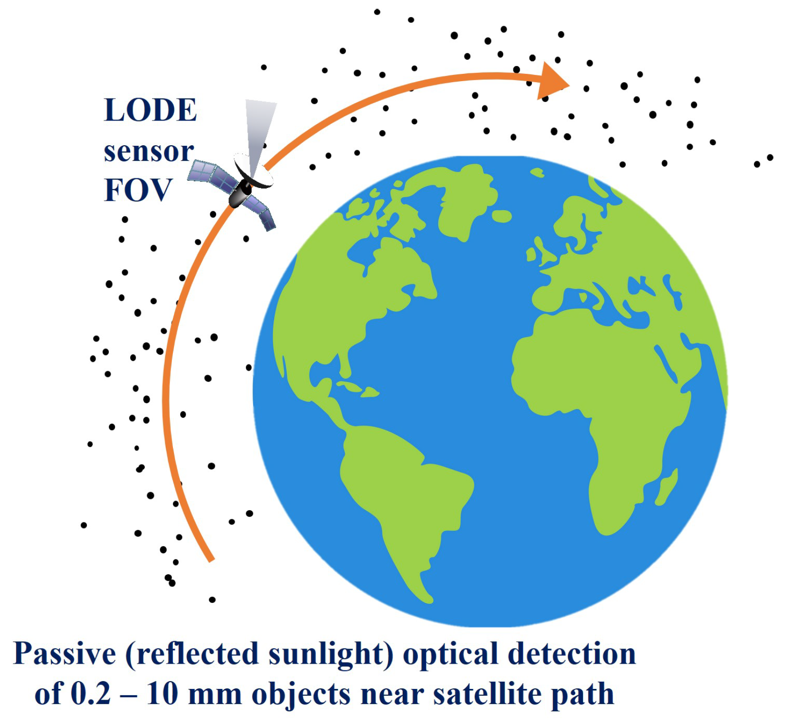
2.1. Optical Telescopes
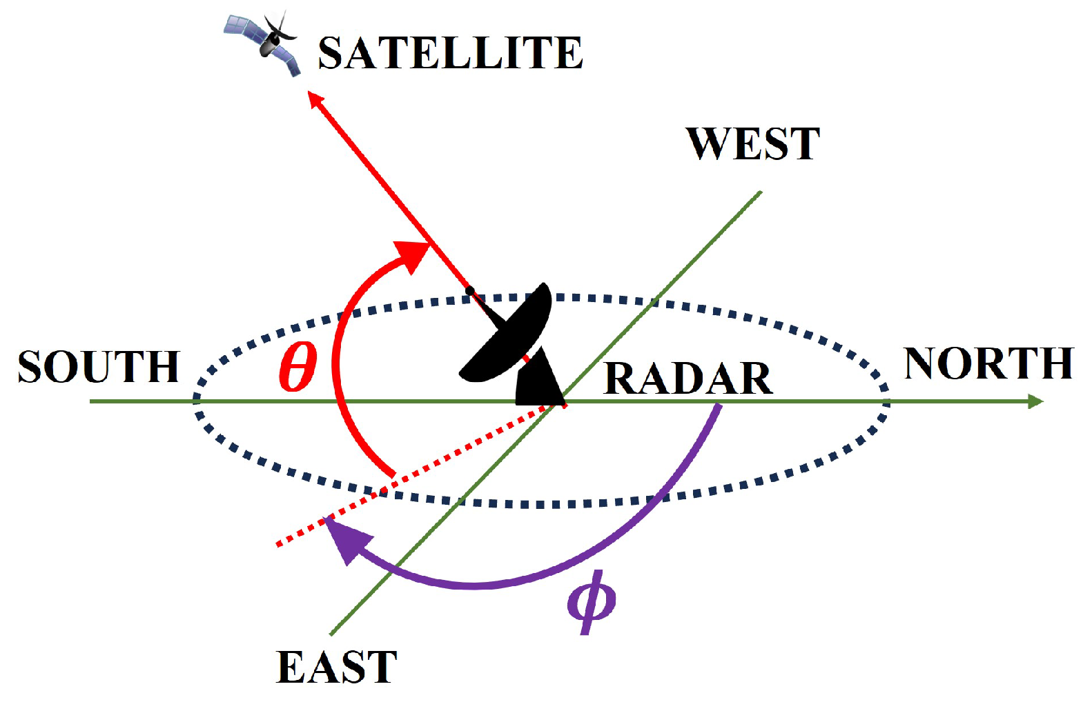
One of the principal methods employed to observe space debris includes optoelectronic observations, which enable the direct acquisition of angular and photometric measurements. The magnitude of optical observations can be influenced by several factors, including the geometry, size, altitude, and physical properties of the object. By accounting for these considerations during optical observations, valuable information regarding space debris can be obtained [46,47].
Ground-based telescopes can detect debris as small as 10 cm in GEO, despite the large observational distance of over 36,000 km [48,49]. The optical measurements made through these ground-based optoelectronic telescopes possess notable advantages such as high precision and cost-effectiveness. However, ground-based optical observations face significant limitations due to weather conditions, which can hinder the continuity of observations [49]. Therefore, it becomes necessary to employ optical sensors on spacecraft or satellites, such as the Local Orbital Debris Environment (LODE), to ensure continuous monitoring. It is deployed on a spacecraft and operates by detecting solar photons (within the visible range) that are reflected by debris passing through its field of view, as depicted in Figure 7. This sensor is designed to locally characterize the population of debris within a specific distance from the satellite orbital path. To achieve optimal observation geometry in low Earth orbit (LEO), the sensor is typically pointed in a general antisolar direction on a spacecraft following a dawn–dusk (equator crossing) Sun-synchronous orbit. The LODE instrument can be deployed either on a dedicated small satellite or as a hosted payload [36].
The LODE concept proposes a new method for detecting debris in space using micro channel plate (MCP) based position-sensitive detectors (PSD). Traditional optical sensors used charged-coupled device (CCD) detectors, which required a large number of photons for reliable detection. In contrast, the LODE instrument utilizes MCP-based PSDs that can determine the coordinates and detection time of individual photons in real time. This allows for the detection of sub-millimeter and millimeter debris near the satellite path. Unlike CCDs, MCP-based PSDs do not accumulate frame images but can form images over any desired time interval while preserving timing information. The technology readiness levels of MCP detectors, readout electronics and power supplies are high, as they have been extensively used in various applications, including the Hubble Space Telescope [36,50,51].
NASA utilizes optical telescopes to passively observe sunlight reflected by debris, enabling routine monitoring of objects in both low Earth orbit and geosynchronous orbital regimes. By integrating optical and radar measurements through the ORDEM model, NASA gains a comprehensive understanding of the orbital debris environment across different altitudes. The 1.3 m Eugene Stansbery Meter-Class Autonomous Telescope (ES-MCAT) and the Optical Measurement Center (OMC) are currently employed for optical measurement research and geosynchronous survey observations of the orbital debris environment. These instruments play a crucial role in gathering essential data for studying space debris [52].

2.2. Radar

Unlike optical telescopes, radars are not affected by weather conditions and can be conducted at any time throughout the day. Radars offer the capability to measure various parameters, including the round-trip time of the signal, Doppler shift between transmitted and received frequencies, azimuth angle ( ϕ ), elevation angle ( θ ) as well as changes in received power and polarization within the radar pulse [53]. This versatility allows radars to provide valuable data without being affected by atmospheric limitations. As shown in Figure 8, the elevation angle ( θ ) measures the angle between the horizontal plane and the line from the observer to the object [54]. The projection of the latter on the horizontal plane is clockwisely rotated by the azimuth angle ( ϕ ) from the geographical north. In radar applications, this angle helps determine the horizontal direction of the target.
A radar serves as a vital tool for detecting orbital debris by emitting electromagnetic radiation toward satellites or debris, which subsequently undergoes reflection. The reflected radiation can be captured by the same radar (monostatic radar) or a different radar situated kilometers away (bistatic radar). Through the interaction between electromagnetic radiation and orbital debris, a portion of the incident radiation scatters back to the receiving radar, enabling the evaluation of object detectability. This detectability is quantified using the radar cross-section (RCS), which relies on variables such as object size, radar wavelength, shape, geometry and material composition. The RCS is quantified as the ratio of the power scattered back to the radar receiver over the incident radar power density per unit solid angle on the target, assuming isotropic radiation. In other words, RCS represents the amount of radar energy scattered in the direction of the radar relative to the power density intercepted by the target [55,56]:
RCS = lim r 4 π r 2 | E s | 2 | E i | 2 ,
  • In Equation (1), RCS represents the radar cross-section, r is used as a representative distance between the radar and the target for RCS calculation and E s refers to the power of the radar signal scattered back to the radar, while E i represents the power of the radar signal incident upon the target. The RCS value is affected by variables such as frequency, polarization, target shape and composition. For simple targets, the RCS can be estimated using analytical approximations found in traditional radar references. However, for more complex scenarios, numerical solvers are necessary to accurately calculate the RCS [55,56,57,58].

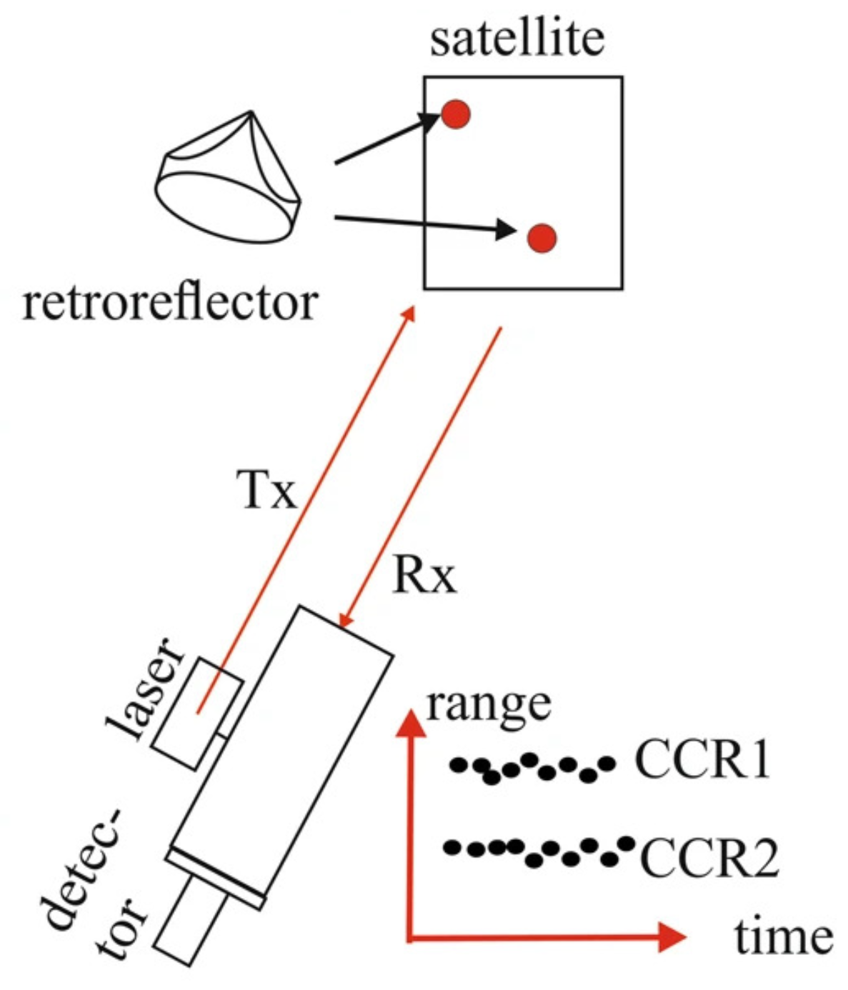
2.3. Debris Laser Ranging (DLR)

Debris Laser Ranging (DLR) is a highly precise real-time measurement technology used to observe space debris [39,40,41,42]. In 2004, Electro Optic Systems, an Australian company, built a DLR telescope with a 1.8 m aperture. They successfully conducted measurements on space debris measuring 10 cm in size at a distance of 1000 km, employing an average laser power of 100 W [41,59].
The effectiveness of debris laser ranging in measuring the size of space debris in daylight was demonstrated by Steindorfer et al. [42]. The observations primarily focused on three different types of rocket bodies from Zenit, Tsyklon or Vostok with launches conducted between 1971 and 1995. Successful space debris passes were recorded during these measurements, applying the criterion of daylight (when the elevation of the Sun is above the horizon).
A key aspect of evaluating the accuracy of the DLR measurements involved analyzing the observed-minus-calculated (O-C) residuals. These residuals indicated a slight underestimation of the time bias used to center the target due to the imperfect alignment of the optical axis. To improve the detection probability, adjustments were made to the triggering time based on the returning photons. By applying time and range biases to the predicted orbit, the measured values were closely matched to the predicted ones, resulting in residuals close to zero. This enabled the identification of fine structures and the estimation of the minimum size of objects. Furthermore, the laser ranging technique detected returns from both the front and back of the rocket body, indicating range differences up to 8 m. These differences indicated the size of the targets. Overall, the laser ranging technique proved valuable for accurately measuring the size of space debris and capturing important details about its characteristics [42].
Satellite Laser Ranging (SLR) is shown in Figure 9, which employs a pulsed laser (Tx) that is directed toward the satellite and subsequently retro-reflected back to the ground station using one or more retro-reflectors. These retro-reflectors, referred to as corner-cube retro-reflectors (CCRs), possess three perpendicular reflecting surfaces, enabling efficient retro-reflection. The reflected light carrying the signal (Rx) is then captured by a telescope and photon detectors located at the ground station. Accurate distance measurements between the ground station and the satellite can be obtained by measuring the travel time of photons using an event timer, providing precise distance calculations [60].

2.4. In Situ Sensors

Since 2002, the NASA Orbital Debris Program Office has been instrumental in supporting the development of particle impact sensors, with the ultimate objective of conducting in situ measurements to enhance our understanding of the population of smaller objects or orbital debris, particularly those measuring millimeters or smaller, in the LEO [61]. The exclusive and effective method for quantifying the flux of small debris, specifically objects with a diameter less than 1 mm, is through space-based in situ impact sampling [62]. An outstanding advantage of employing in situ measurements is the ability to acquire data with a high temporal resolution, facilitating the examination of variations within the aforementioned environment [63]. The objective of space-based observations is to assess the flux of submillimeter micrometeoroids orbital debris (MMOD) by analyzing retrieved spacecraft surfaces. Due to cost considerations, these surfaces are predominantly obtained from missions in low Earth orbit (LEO) [62].
The data obtained through space-based in situ impact sampling, made possible by the support of the NASA Orbital Debris Program Office for particle impact sensors, are a valuable resource for various models. Notably, models such as ESA’s MASTER (Meteoroid and Space Debris Terrestrial Environment Reference) and NASA’s ORDEM (Orbital Debris Engineering Model) utilize these data to deliver precise depictions and comprehensive analyses of the population of small-sized debris in the space environment [63,64].
The Wide Field Planetary Camera 2 (WFPC-2) provides an excellent example of an in situ measurement, having completed a remarkable mission duration of approximately 16 years while in orbit aboard the Hubble Space Telescope before its safe return to Earth. Throughout its operational lifespan, the radiator of the WFPC-2 endured exposure to the challenging environments of micrometeoroids and orbital debris, rendering it a valuable resource for investigating the characteristics of the MMOD environment. A meticulous examination of the radiator yielded significant impact features and distinctive craters within the thermal paint layer. Through careful extraction and thorough examination of these craters, researchers employed advanced techniques to determine the probable origins of the objects responsible for the impacts. Furthermore, a novel approach was developed to overcome the limitations associated with crater imaging and analysis, thereby making notable strides in advancing our understanding of the MMOD environment. This research not only contributes to the enhancement in space debris mitigation strategies but also deepens our comprehension of the intricate dynamics of space debris in Earth’s orbit [43].
The impact analysis of the Bay 5 multi-layer insulation (MLI) on the Hubble Space Telescope (HST), as illustrated in Figure 10, reveals complex impact features and multiple-layer penetrations. The imagery showcases a through-hole with the left image offering a close focus to the observer, while the right image emphasizes the exit hole. Conducted by the NASA Orbital Debris Program Office, this meticulous analysis enhances our understanding and enables more accurate estimation of particle parameters for objects impacting the near-Earth space environment [43].
Serious efforts were made by various space agencies to mitigate the issue of increasing debris. In recent decades, several methods have been suggested in order to capture and remove space debris [65,66,67,68,69,70,71,72,73,74]. These methods are divided into: Contact capturing methods, contact-less capturing methods [70,75] and self-eating satellite. The framework of methods for capturing space debris is depicted in Figure 11.

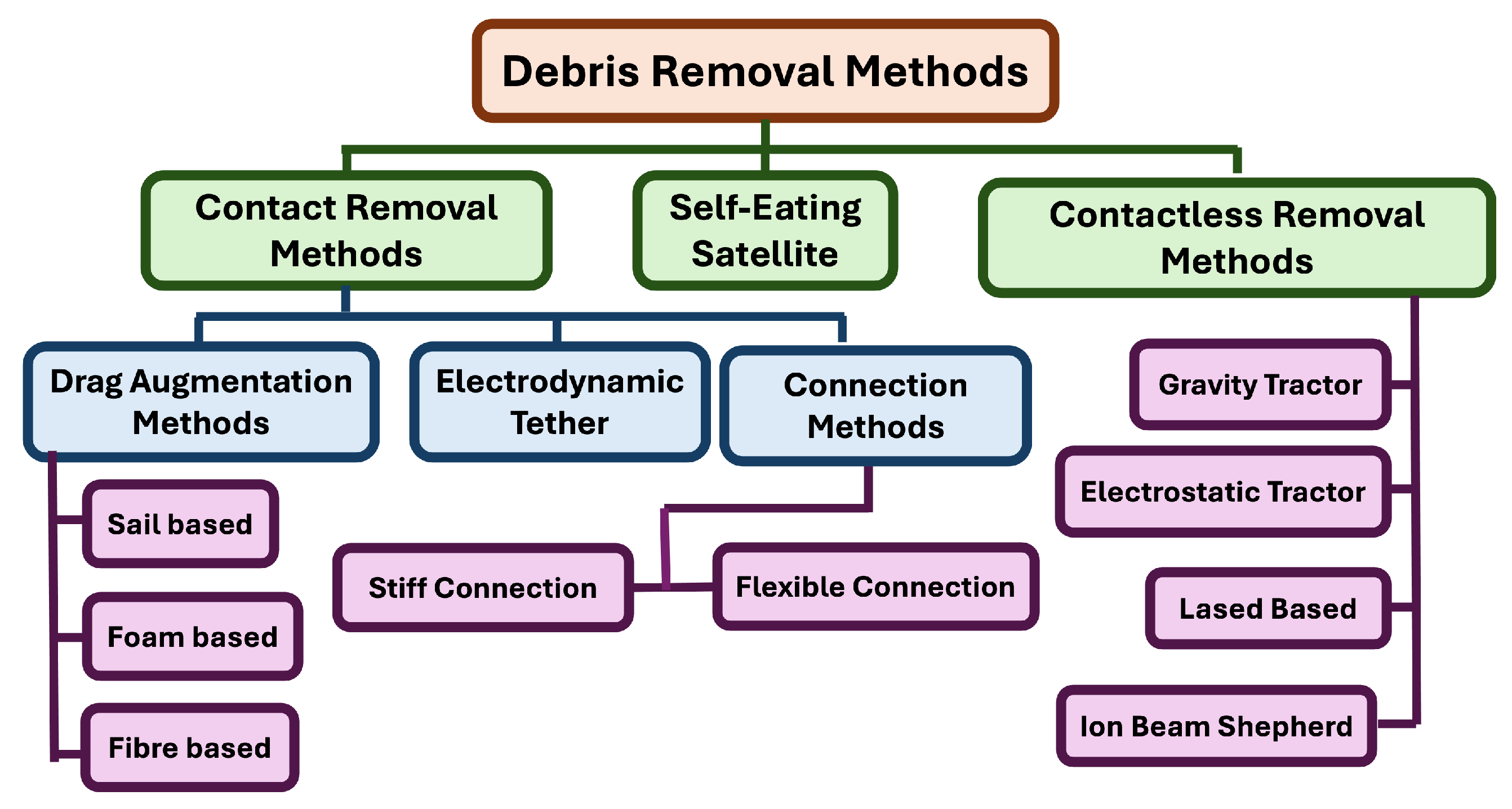
2.5. Contact-Less Debris Removal Methods

In the contact-less debris removal method, an external force is applied in a controlled manner to de-orbit debris, resulting in its atmospheric re-entry (see Figure 12). For example, an energetic plasma beam is projected from a spacecraft toward the debris. This creates an opposite charge on the debris, resulting in its deceleration, hence facilitating the re-entry of space debris into the Earth’s atmosphere, where it would burn up [76,77].
Other contact-less capture methods include the gravity tractor [79] or an electrostatic tractor [80], which use external forces such as gravitational or electrostatic forces to deflect the space debris. While contac-tless debris removal methods, such as laser ablation and electrostatic tractors, provide the advantage of non-invasive maneuvering, their effectiveness is constrained by high energy demands and reduced efficiency over long distances. Furthermore, the large-scale deployment of these technologies remains uncertain due to both technological limitations and regulatory challenges.

2.5.1. Gravity Tractor

Lu and Love [79] presented a conceptual design of a spacecraft that uses gravitational force to alter the trajectory of an asteroid. In their design, they proposed that the spacecraft hover near the asteroid with its thrusters directed outwards, deflecting the asteroid from its trajectory. This method is unaffected by the structure, surface or rotation state of the asteroid [79].

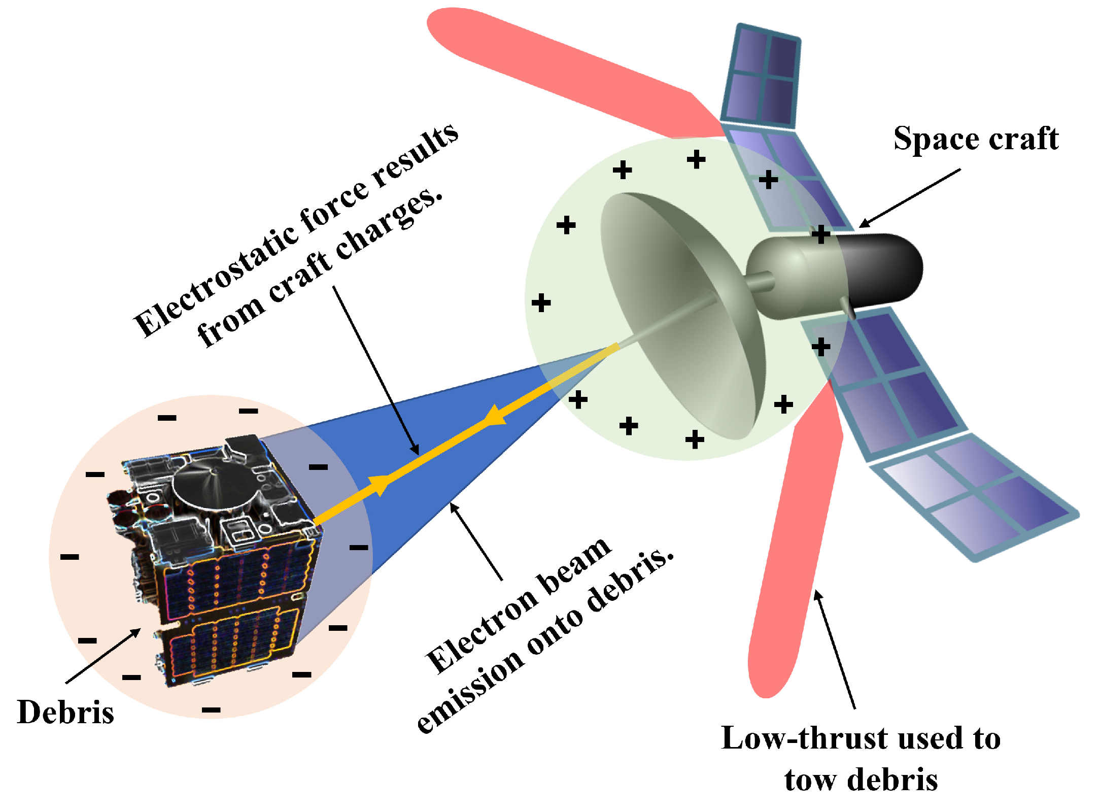
2.5.2. Electrostatic Tractor

The electrostatic tractor approach uses Coulomb forces to de-orbit space debris. In this method, a spacecraft (a tug vehicle) approaches space debris (a rocket body or a dead satellite) and emits an electron beam at it. The target (debris) becomes negatively charged due to the storage of additional electrons, while the tug vehicle that emits electrons becomes positively charged. Thus, the resultant attractive force between two opposite charged bodies (the tug vehicle and the debris) is used to initiate the de-orbiting process of debris without any physical contact [81,82].

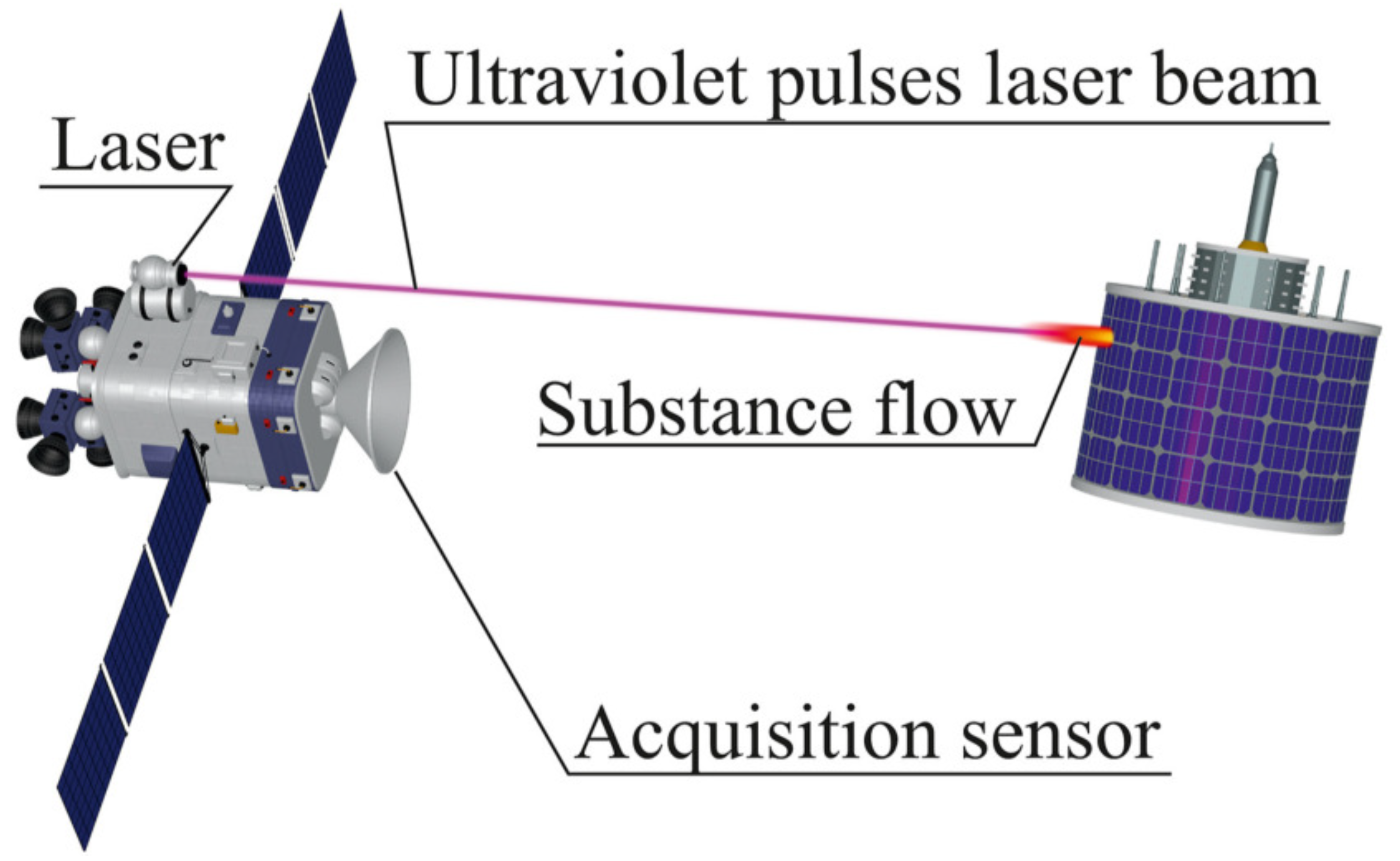
2.5.3. Laser-Based Method

Laser ablation-induced propulsion has emerged as a promising technique for space debris removal, involving remote irradiation from a service spacecraft to generate a propulsion impulse using a laser [83]. This method is effective through two primary modes: direct ablation and ablation back-jet.
In the direct ablation mode, laser energy targets small debris particles, burning them down completely. In contrast, the ablation back-jet mode is designed for larger debris particles, using laser energy to alter their orbits. As the laser energy irradiates the debris, it converts into thermal energy, heating the debris surface to its melting or boiling point. When the temperature reaches the vaporization point, plasma is produced and expands at speeds much higher than the speed of sound, creating a reaction force that changes the debris’ trajectory. With repeated laser pulses, the perigee altitude of the debris is gradually reduced, leading to aerodynamic heating and eventual burn-up. For debris particles with a perigee of less than 200 km, re-entry into the atmosphere occurs within a few days. In contrast, debris with a 500 km perigee has a natural decay time of approximately 18 years, making 200 km a critical threshold for effective removal [84].
A concept validation study by NASA headquarters further supports the feasibility of using pulsed lasers to eliminate nearly all hazardous orbital debris ranging from 1 to 10 cm in size at altitudes between 400 and 1100 km within two years. The study concluded that this laser-based debris removal approach would be relatively low-cost compared to the expenses associated with shielding, repairing or replacing valuable spacecraft potentially damaged by debris impacts [85].
Both space-based and ground-based lasers hold significant potential as foundations for developing just-in-time collision avoidance systems [86]. One of the major advantages of this method is that it is contactless, meaning there is no physical interaction with space debris [83]. Laser orbital debris removal (LODR) is effective even for large debris objects and is considered to provide the lowest cost per object removed among all proposed approaches. Furthermore, LODR is unique in its ability to handle both small and large debris. It allows for target access at the speed of light, making the system redundant and agile. Unlike mechanical grapplers, LODR can handle tumbling objects. Additionally, the system offers multiple uses beyond general debris clearing, such as preventing collisions, increasing the accuracy of debris ephemerides and controlling where large debris impact the Earth’s surface [77]. However, there are notable disadvantages to the laser-based method, particularly for space-based systems, which include the high launch costs associated with deploying them and the difficulty in repairing these systems once they are operational in space [85].

Space-Based Lasers

In space-based applications, one of the key projects utilizing the ablation effect is the Laser Ablative Debris Removal by Orbital Impulse Transfer (L’ADROIT). This spacecraft is equipped with a 100 ps ultraviolet pulse laser and compact optics, as shown in Figure 13, which are capable of detecting large space debris from distances of up to 600 km and affecting it from 250 km. These lasers are particularly effective for impacting debris in low Earth orbit (LEO). According to estimates, altering the orbit of a 1000 kg debris object by 10 km in a circular orbit at an altitude of 760 km requires a velocity increment ( Δ V ) of 0.52 m/s, achievable with 14 min of laser exposure [86].
The L’ADROIT system is a solar-powered, space-based technology designed for efficient removal of orbital debris, especially fragments smaller than 10 cm that are difficult to clear with mechanical methods. The system includes two interconnected telescopes and a power-efficient ultraviolet (UV) pulsed laser specifically optimized for deorbiting space debris.
One telescope has a wide field of view and acts as a passive sensor, detecting and identifying debris. The second telescope, with a narrow field of view, is responsible for active targeting and tracking of the debris. Once a target is locked, this telescope focuses the laser and fires repeated UV pulses at a wavelength of 355 nanometers, produced by the third harmonic of a neodymium (Nd) laser. Each pulse delivers approximately 500 joules and lasts around 100 picoseconds, creating precise, high-intensity bursts that vaporize portions of the debris surface.
By directing these pulses in a head-on alignment with the debris, the L’ADROIT system maximizes momentum exchange. This targeted approach ensures effective orbital alteration, ultimately slowing the debris enough for it to re-enter Earth’s atmosphere and burn up. Unlike ground-based laser systems, this spaceborne design offers superior momentum coupling, as it operates at close range and aligns optimally with debris trajectories. L’ADROIT is an efficient and cost-effective solution for managing hazardous space debris in low Earth orbit [85,87,88].

Ground-Based Lasers

Ground-based lasers represent a promising approach for space debris removal, particularly for eliminating centimeter-sized debris in low Earth orbit (LEO). These systems require bulky adaptive optics to compensate for atmospheric turbulence.
The LightForce project exemplifies this approach, utilizing ground-based continuous-wave (CW) lasers combined with adaptive optics for just-in-time collision avoidance. This project leverages the pure photon momentum transfer effect, where multiple ground-based CW lasers illuminate the target fragment during successive overhead passes, gradually increasing its along-track displacement [86,89,90]. These strategies rely on the debris fragments being sufficiently large or bright to be optically tracked from the Earth’s surface at distances over 500 km. Additionally, these methods often require multiple engagements with individual fragments to maximize displacement, necessitating precise knowledge of the objects’ orbits for effective re-engagement [89].
As shown in Figure 14 the removal mechanism of these ground-based laser systems operates as follows: First, the precise position of the orbital debris is monitored and detected by the laser system. Subsequently, a high-power laser, with a power density exceeding the breakdown threshold, is directed at the surface of the debris using a tracking and aiming transmitter combined with an adaptive optical system. The laser imparts a velocity increment to the debris, causing it to gradually descend into the Earth’s atmosphere, where it ultimately burns up upon re-entry. This process effectively removes the debris from orbit [77,91].

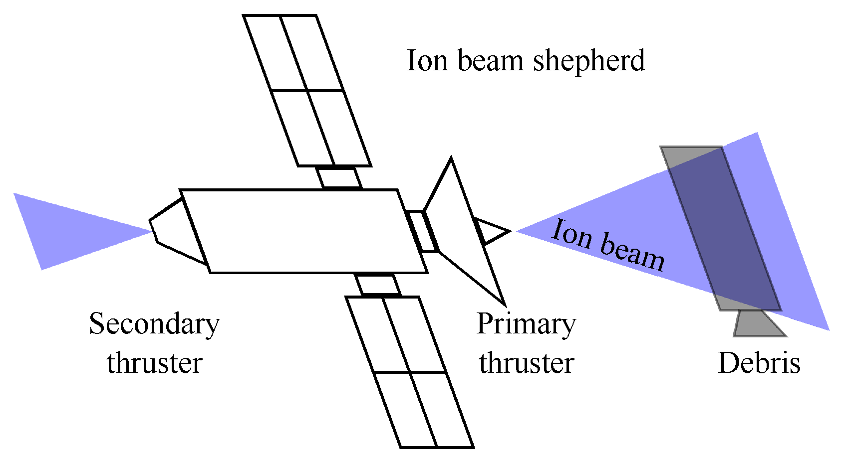
2.5.4. Ion Beam Shepherd (IBS)

An Ion Beam Shepherd (IBS) satellite employs an onboard electric thruster to direct a plasma beam at a target object, typically space debris. As depicted in Figure 15, the ion beam interacts with the target, applying a net surface force that transfers momentum to it. This results in the target experiencing acceleration, which can be used to remotely alter its trajectory, potentially leading to its de-orbiting or re-orbiting. In practice, the target does not capture all the plasma emitted by the thruster, as the plasma plume expands and only a portion of the momentum is imparted to the target. The momentum transfer efficiency, denoted as η B , is the fraction of momentum actually captured by the target, or the ratio between the net force acting on the target and the force generated by the thruster. The thruster responsible for transmitting momentum is referred to as the primary thruster or momentum transfer thruster. Therefore, if F 1 is the force produced by the primary thruster, then η B F 1 is the effective force exerted on the target.
This force F 1 also causes a reaction force on the IBS satellite, pushing it away from the target. To maintain a stable distance between the IBS and the target, a secondary thruster, known as the thrust compensation thruster, is required to counteract this drift. The secondary thruster generates a force F 2 on the IBS, opposing the force of the primary thruster, resulting in a net force on the IBS of F 2 F 1 . It is assumed that both the IBS and the target follow a similar quasi-circular orbit, and under the Clohessy–Wiltshire approximation, their relative motion remains linear, with these net forces acting tangentially to the orbital velocity [92].
One of the key advantages of the IBS method is the absence of direct mechanical contact between the active spacecraft and the space debris. This greatly enhances safety by eliminating the risk of accidents during capture or docking. Additionally, the system is not sensitive to the angular motion of the debris, enabling it to displace even rapidly rotating objects. The contactless nature of this method also allows for safer maneuvering and removal of hazardous debris without the complexity and risks associated with physical interaction. However, a significant limitation of contactless transportation using an ion beam is the relatively low magnitude of the generated force. This small ion force results in longer transportation times, increasing the risk of collisions with other space debris, especially in densely populated orbital regions. According to current guidelines, the descent of space debris to Earth must not pose significant risks to people or property. For large debris in low Earth orbit (LEO), controlled re-entry is essential, but the ion force generated may not be sufficient for this task. To address this, the ion force could be increased by either boosting the ion outflow velocity or its concentration, which would require upgrades to the ion engines being used. Additionally, the power requirements for continuous operation of the ion thrusters are substantial, which poses a challenge for long-duration missions. The complexity of coordinating the primary and secondary thrusters to maintain precise positioning relative to the target further complicates the operational aspects of the IBS system [93,94].

2.6. Contact-Based Debris Removal Methods

2.6.1. Drag Augmentation Method

Drag augmentation represents a passive and effective approach for de-orbiting satellites in low Earth orbit (LEO). At altitudes below 1000 km, a thin atmospheric layer exerts drag on orbiting objects, gradually causing them to spiral toward Earth. While satellites in this region naturally decay over time, the duration of this process significantly depends on factors such as initial altitude, satellite mass and drag surface area. In the drag augmentation technique, the drag surface area is increased with minimal additional mass which can lead to significant reduction in the time required for orbital decay. Traditionally, sail designs explored for solar sails are increasingly considered for de-orbiting applications. These sails have low mass and large surface area that expedite the de-orbiting process [95,96].

Sail-Based Method

The sail-based method operates on principles of drag augmentation for the removal of space debris. This approach involves deploying a sail on a satellite, which increases drag and facilitates orbital decay. The sail also harnesses the pressure of solar radiation to alter the satellite’s orbit [97]. This method offers a propellant-free solution, using sunlight to generate thrust and gradually de-orbit the satellite at the end of its operational life. The deployment of the sail and its orientation toward the sun are controlled remotely, typically from a ground station. As illustrated in Figure 16 [98], this method is also applicable when a chaser satellite captures debris using harpoon or net capturing techniques; after the capture, the satellite can deploy the sail to de-orbit the debris without requiring additional propellant. However, the need for precise sail deployment and maintaining the correct orientation relative to solar radiation can still necessitate some propellant use, which is a limitation of this method [97,99].
An example of early research in this area was conducted by NASA Langley Research Center and ATK Space Systems, where a 20 m solar sail was tested as part of a ground demonstrator program. The tests were conducted in a vacuum environment, aimed to validate analytical models crucial for predicting in-space performance during flight tests. Various excitation methods, including magnetic excitation and piezoelectric actuation, were employed to assess the sail system dynamics, and the influence of several factors such as membrane geometry, mass distribution and sail tensioning forces were analyzed. This research provided significant insights into the behavior of solar sails in space, contributing to the development of effective space debris removal technologies [100].
Cranfield University has been actively developing a family of scalable Drag Augmentation Systems (DASs) designed to aid in the de-orbiting of small satellites in LEO at the end of their mission life. These systems are part of a broader effort to comply with international space debris mitigation guidelines and support the conservation of the space environment. The Icarus-1 drag sail, a key project within this initiative, was developed as a demonstrator payload for the TechDemoSat-1 mission. The design focused on ensuring safety, minimizing debris production, maintaining high reliability and achieving low mass (see Figure 17). The sail was constructed using commercial off-the-shelf components to meet budget and schedule constraints while also ensuring compatibility with space debris mitigation guidelines. It successfully deployed in May 2019, demonstrating its effectiveness.
Continuing this work, the Icarus-3, a smaller and simplified version of Icarus-1, was adapted for the Carbonite-1 microsatellite. This version also focused on improving the reliability of sail deployment while simplifying the stowage and deployment process. Icarus-3 was successfully deployed in November 2018, resulting in a significant increase in the satellite’s projected area and drag, as confirmed by both the Defence Science and Technology Laboratory’s (DSTL) analysis and Cranfield University’s assessment of publicly available data. The deployment led to an observable increase in drag and a faster rate of semi-major axis decay, confirming the sail effectiveness and its continued integrity throughout the mission. These results highlight the potential of DAS technology to significantly contribute to space sustainability by providing a reliable, low-cost solution for de-orbiting small satellites, thereby reducing the long-term risks associated with space debris [101].

Foam-Based Method

The foam-based method is an active debris removal technique that leverages expanding foam to enhance the area-to-mass ratio of space debris, thereby increasing the effectiveness of atmospheric drag in de-orbiting these objects. This approach involves a spacecraft, often referred to as a chaser satellite, that rendezvous with the target debris and flies around it before initiating the foaming process [102]. Foam is ejected from a device installed on the chaser onto the target, where it adheres and gradually covers the entire object, transforming it into a foam ball. The area-to-mass ratio is significantly increased due to the foam’s small density and large volume [75].
By eliminating the need for a docking mechanism, this method simplifies the technological requirements and reduces the risks involved in interacting with non-cooperative debris, including those with high angular velocities. The foam structure is engineered to withstand impacts from small pieces of space debris, ensuring that the foam ball remains intact and does not contribute to the creation of new debris [102]. This design provides a reliable alternative to other drag augmentation methods, such as sails, which can be vulnerable to damage during re-entry [75].
However, there are some challenges associated with the foam-based method. The chemical composition of the foam must strike an optimal balance between stiffness and flexibility; if the foam is too soft, it risks being easily damaged, leading to potential debris generation. This need to tailor the foam properties to different types and topologies of space debris represents a significant disadvantage of the method. Furthermore, while the concept has shown promise, its technology readiness level (TRL) remains relatively low, with the highest level reached so far being TRL-4, indicating that it is still in the early stages of development and has not yet been fully tested in space [103,104].
The method effectiveness is further enhanced by the integration of an electric propulsion system, allowing the chaser satellite to successively target multiple pieces of debris within a single mission. Once the mission is complete, the satellite can use the same propulsion system to de-orbit itself. The method’s success depends on achieving an optimal balance between the size of the foam ball and the desired de-orbiting time, as well as selecting the most suitable foam material. Ongoing discussions continue to refine the choice of foam material and the optimal de-orbiting period to ensure that debris re-enters the atmosphere within a specified time-frame, such as 25 years, in accordance with established guidelines for space debris mitigation. This approach is particularly effective for managing large debris, as the foam can be adjusted to significantly increase drag without the need for complex mechanical systems [75,102].

Fiber-Based Method

The fiber-based method for space debris mitigation involves the in-space production of fiber-based debris interceptors. These interceptors are created by a spacecraft equipped with a material supply and specialized devices that produce fibers through various methods such as extrusion, chemical vapor deposition, blow forming or mechanical shaving. Once produced, these fibers are mechanically coupled together, forming an interceptor that interacts with and captures space debris. The fibers used in this method are typically very thin, less than 100 microns in diameter, to minimize the risk of generating new debris while effectively slowing down or capturing existing debris. This technique allows for applications such as clearing orbits before the deployment of new spacecraft, protecting operational satellites from potential debris impacts and encapsulating non-functional satellites to prevent further debris generation. The deployment of these fiber-based interceptors can occur either before or after the launch of a spacecraft, depending on the specific mission requirements. The fibers can be made from various materials, including metals like aluminum or polymers like nylon, chosen for their suitability in space. Additionally, the high area-to-mass ratio of these fibers ensures that any loose fibers will de-orbit relatively quickly, reducing the long-term risk of creating additional debris [105].
However, it is important to note that the fiber-based method has seen limited research and practical implementation. The technique remains largely theoretical, and further investigation is necessary to assess its feasibility and effectiveness in real-world applications.

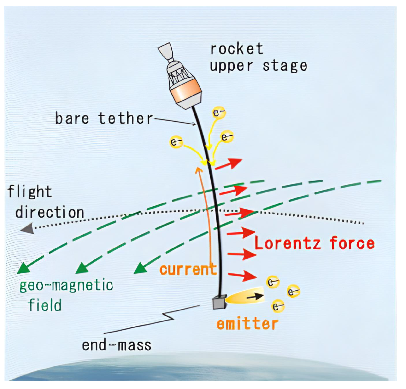
2.6.2. Electrodynamic Tethers (EDTs)

An electrodynamic tether is essentially a long, flexible and thin electrically conductive wire that extends from a spacecraft. The gravity gradient field causes the tether to stretch and align itself, pointing toward the Earth’s center. As the spacecraft and tether travel at orbital speeds through the geomagnetic field, a voltage is induced along the tether, generating a current. This current creates a Lorenz force that can either accelerate or decelerate the tethered object (such as space debris). Thus, by attaching EDT space debris, the system can slow the debris down. This reduction in velocity causes the debris to gradually fall into a lower orbit, ultimately leading it to re-enter Earth’s atmosphere and burn up. An EDT can achieve deceleration without requiring propellant or significant electrical power, making it a potentially efficient option for de-orbiting debris. Additionally, EDTs present potential as next-generation propulsion systems, offering a non-chemical means of generating thrust. Furthermore, EDTs show potential as a propulsion system for de-orbiting large debris objects from LEO and could contribute to space environment preservation if further developed and implemented (see Figure 18) [106,107].
In the exploring EDT systems for space debris removal, two key approaches have been identified: expendable and reusable systems. The expendable system, as shown in Figure 19, is designed to be efficient and lightweight, incorporating up to 10 small EDT units in the removal mechanism. Each unit is capable of attaching to individual debris objects, guiding them into lower orbits for disposal.
In contrast, the reusable system, illustrated in Figure 20, adopts a more complex approach, utilizing a single EDT unit repeatedly. In each full cycle, the tether attaches to debris, descends it to a disposal orbit, and then returns to a higher orbit to continue its operations. This system could benefit from employing two hollow cathodes, one for the emitter and one for the collector, since the ability to reverse the current is essential for its functionality. While the reusable EDT system offers increased capabilities and efficiency, it also presents technical challenges, particularly in generating sufficient electrical power to counteract the electromotive force and reverse the current [108].
The EDT method for space debris removal is distinguished by its high mass efficiency, as it does not rely on propellant, maintaining a low system weight even for missions involving significant velocity changes. Its simple design, eliminating complex components such as propellant tanks and valves, makes the system compact and straightforward. Additionally, the power consumption of an EDT system is relatively low, owing to its use of naturally induced electromotive force.
Key features of EDT includes the ease of attaching the system to debris without requiring precise alignment with the debris’s center of mass, and the elimination of the need for thrust vector control. The tether’s flexibility reduces the transmission of loads between connected modules compared to rigid joints, allowing the chaser vehicle to remain at a safe distance during deorbiting. The use of tape tethers improves survivability against space debris impacts and enhances electron collection performance, contributing to faster deorbiting.
However, the system also has limitations. The low thrust generated by the tether means that deorbiting debris can take several months to a year, necessitating autonomous operation to reduce costs. Additionally, there is a risk of the tether being severed by collisions with small debris or micro-meteoroids, potentially terminating the mission prematurely. This risk can be mitigated by using a reinforced net-type tether.
The long tether also increases the risk of collisions with operational satellites, requiring thorough risk assessments before deployment. The deployment phase itself poses challenges, such as issues related to libration stability and oscillations, which can destabilize the system. Controlled deployment and retrieval operations introduces additional technical challenges, requiring advanced mechanisms to manage these operations effectively. Finally, the system’s low thrust complicates controlled re-entry, necessitating careful consideration of potential risks to people and property on the ground the deorbiting process [109,110].

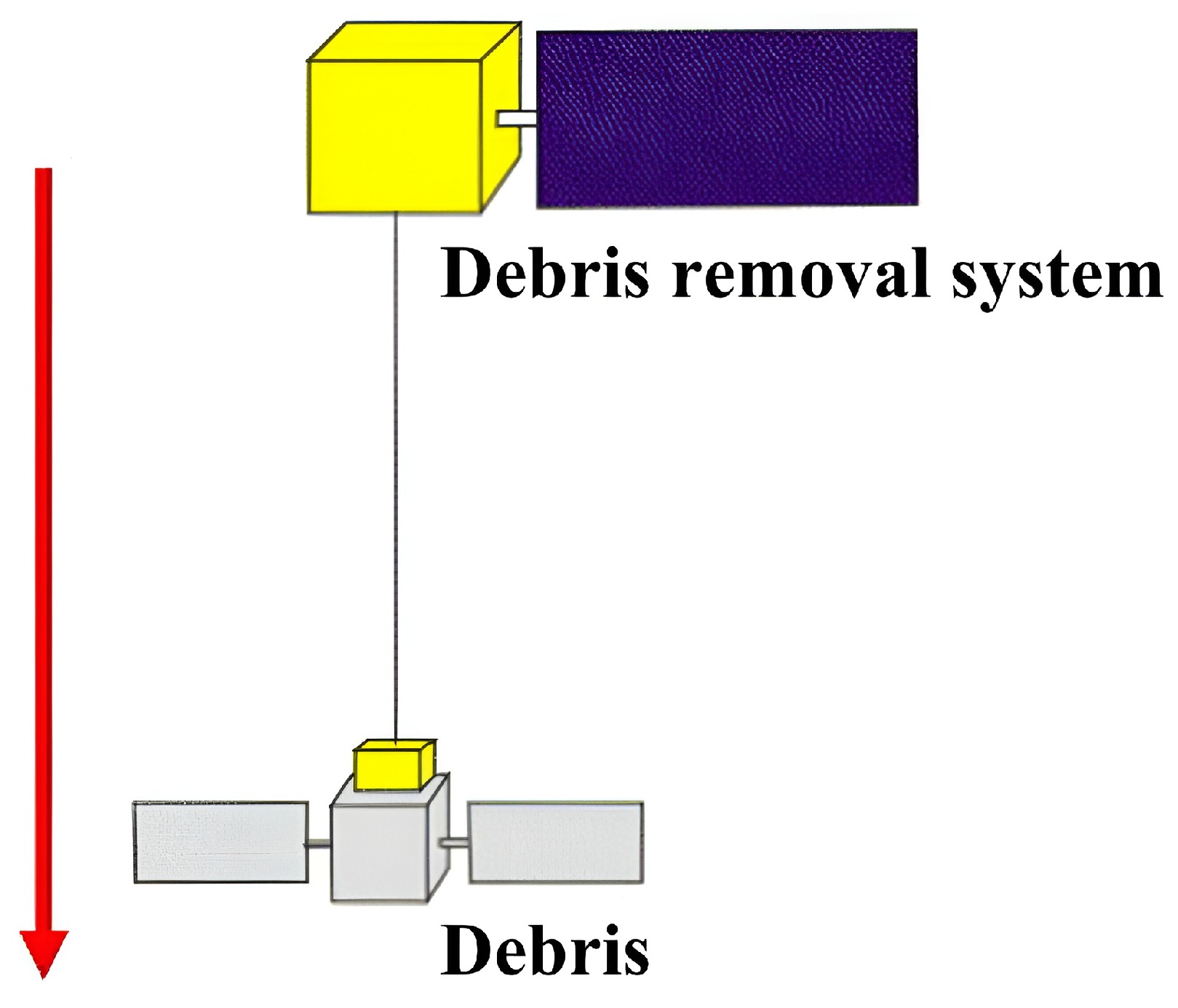
2.6.3. Stiff Connection-Based Methods

The contact connection capturing methods for the removal of space debris (see Figure 21) are classified into two main, the stiff and the flexible connection methods [65,71,111,112]. The stiff connection methods are broadly classified as in the following.
Tentacles capturing: The tentacle capture method features flexible appendages that grasp the debris at several points rather than latching onto a single point, as in the case of the robotic arm capturing method. The tentacle capture method can be used with or without the utilization of a robotic arm. In the case of the robotic arm tentacle capture method, a clamping mechanism is used to capture the object or debris. Then, it performs a controlled re-entry of debris into the atmosphere, where the debris is finally burned up [113]. On the contrary, the tentacle capturing without a robotic arm is based on a docking mechanism. The docking clamp on the chaser is designed according to the shape of the targeted debris [75]. Thus, debris is locked within the chaser clamp and is ultimately de-orbited. The tentacle capturing methods are easy to test and have a higher technology readiness level (TRL). However, these methods are not cost-effective [75].
The European Space Agency (ESA) plans to launch the ClearSpace-1 mission in 2028, which aims to capture and remove the PROBA-1 satellite. This mission is led by OHB SE (German space company) in collaboration with ClearSpace, a Swiss startup, and researchers from the École Polytechnique Fédérale de Lausanne (EPFL). The PROBA-1 satellite, launched in 2001, is a small satellite with dimensions of 0.6 m × 0.6 m × 0.8 m, currently in low Earth orbit. ClearSpace-1 will use a sophisticated tentacle capture mechanism to grab and de-orbit the satellite. The mission, a significant development in space debris removal, highlights ongoing efforts by space agencies to address the growing issue of orbital debris [114,115]. However, despite advancements in debris removal techniques, no debris has been removed yet. The slow pace of developing space-cleaning technologies raises concerns about the increasing amount of debris, which threatens to limit available orbital space for future launches.
Robotic Arm Method: The robotic arm capture method is used for custom-designed satellites that have installed markers. These markers can be easily gripped by the end effector of the robotic arm. Thus, this mechanism is highly reliable and reusable [116]. The process of capturing space debris using a robotic arm involves a series of carefully coordinated operations. After completing both far and close-range rendezvous maneuvers with the target satellite, the servicing spacecraft maintains a safe, station-keeping distance from the tumbling target. The capture operation is then initiated, which can be divided into four distinct phases (illustrated in Figure 22). The first phase involves observing and planning, during which the system gathers motion and physical property data about the target satellite to devise a strategy for the robotic manipulator to grasp the target. In the second phase, the robotic arm is controlled to move toward the pre-determined grasping location, positioning itself for capture. The third phase is the actual capture, where the manipulator physically intercepts and grasps the capturing device of the target satellite. Finally, in the fourth phase, known as the post-capture phase, the captured target is stabilized along with the servicing spacecraft [117]. After stabilization, a velocity increment by the servicing spacecraft is applied to de-orbit the target, guiding it into the Earth’s atmosphere for controlled re-entry [75]. This comprehensive process highlights the complexity and precision required in using robotic arms for space debris capture, especially when dealing with non-cooperative and tumbling objects.
Recent advancements in robotic arm-based debris removal systems have focused on enhancing compliance control, adaptive manipulation and multi-arm coordination. Researchers have explored robust control techniques, such as fast terminal sliding mode control (FSTSMC) for compliance in dual-arm space robots, which enhances precision in capturing debris while mitigating dynamic disturbances. In particular, a Spring Damper Buffer Device (SDBD) was introduced to protect robotic joints from impact forces during debris capture. The SDBD absorbs impact energy and ensures stable control of the hybrid system by matching compliance strategies with dynamic constraints. The system dynamics, derived using the Lagrange function, integrate velocity constraints and closed-chain geometric relationships to optimize post-capture stability [118].
Additionally, integrated sliding mode control (ISMC) strategies have been developed for space robots with flexible-base, flexible-link and flexible-joint (FBFLFJ) configurations. Traditional ISMC methods struggle to maintain stability and precise motion control, but FBFLFJ configuration provides inherent structural flexibility to the space robots. This method achieves vibration suppression improvements ranging from 50% to 80% and enhances trajectory tracking accuracy by 37% compared to traditional ISMC methods lacking vibration suppression. Furthermore, the upgraded ISMC approach ensures stable control while considering actuator constraints and leveraging output feedback control, making it a suitable solution for real-time space operations [119].
It is also observed that robotic arm faces issues such as joint damage caused by the impact torque of a non-cooperative spacecraft during on-orbit capture. To address this issue, a buffer compliance control mechanism is used based on a reinforcement learning control algorithm. The compliant mechanism not only absorbs impact energy through the deformation of its internal spring but also limits the impact torque within a safe range. In the reinforcement learning control algorithm, the dynamics of the space robot and the target spacecraft are formulated using the Lagrange approach and the Newton–Euler method before capture. Following the capture, the integrated dynamic model of the post-capture hybrid system is derived based on the law of conservation of momentum and velocity constraints. The buffer compliance control strategy is used to enhance the stability of an unstable hybrid system. The approach employs an associative search network (ASN) to approximate unknown non-linear functions and an adaptive critic network (ACN) to generate reinforcement signals, optimizing the learning process in real time. Numerical simulations demonstrate that the proposed control scheme effectively reduces impact torque acting on the joints by up to 76.6% at maximum and 58.7% at minimum during the capture phase. Additionally, in the stabilization phase, the impact torque on the joints remains within the safety threshold, preventing overload and structural damage. These improvements enhance the resilience and adaptability of space robots for future on-orbit servicing and debris removal missions [120]. These advancements in compliance control and trajectory optimization significantly improve the reliability of robotic manipulators in space debris capture. However, challenges remain, particularly in capturing debris with high angular momentum.
As shown in Figure 23, a robotic arm, or manipulator, is a well-established and continuously advancing technology. These systems consists of a series of links connected by motorized joints and typically culminate in an end-effector equipped with various sensors. To optimize operational efficiency, spacecraft can be fitted with multiple robotic arms. However, most space manipulators are designed for interaction with cooperative targets that can communicate their status. In contrast, space debris is classified as non-cooperative object, with only approximate knowledge of its mass, geometry and angular rotation rates. This imprecision significantly complicates the use of robotic manipulators for debris capture [86].
One significant disadvantage of using the robotic arm method for space debris removal is its inability to capture debris with high angular momentum. Currently, no space-flown robotic arm can effectively absorb the angular momentum of certain debris, which challenges the efficacy of this method. Additionally, attempting to capture debris with high angular momentum can result in high joint torques, potentially causing mechanical stress or system failure. This limitation indicates that, without prior altitude synchronization maneuvers or advancements in joint actuator technology, the robotic arm method may not be suitable for safely capturing all types of space debris [121].
Despite these challenges, robotic arms remain a viable option for debris capture. They can be employed using either a single-arm method or in combination with multile robotic arms [75].
In particular, the single-arm capturing method employs a robotic arm equipped with sensors and end-effectors to grasp debris objects. To ensure a smoother and safer capture, pre-processing techniques are used to stabilize the debris by reducing its rotational momentum and angular velocity before actual engagement (see in Figure 24). These techniques are critical, especially when dealing with debris that has high angular momentum or complex motion. By slowing down the debris’ rotation to a manageable rate, the robotic arm can securely engage and bring the object under control, overcoming the difficulties posed by high-speed tumbling [66,122].
In Figure 25, the two notable pre-processing methods, i.e., the Flexible Rod and Flexible Brush techniques, are depicted, which are essential for stabilizing the debris and preparing it for capture by the single robotic arm [123].
The flexible rod method is designed to enhance the capture of space debris by providing more controlled contact and interaction with tumbling objects. This method is particularly notable for its deployable flexible beam mechanism, which is effective in reducing the dynamic forces that occur during the docking process, especially when engaging with non-cooperative targets such as defunct satellites or rocket stages.
The method typically involves a two-stage process. The first stage utilizes a flexible impact to synchronize and reduce the target’s angular velocity across all three axes. This is achieved by the making beam contact with the surface of the debris, where its flexible nature allows it to absorb and dissipate impact forces, thus stabilizing the target’s motion. Additionally, the design of the beam allows it to slide along the surface of the debris, particularly around the engine nozzle, which is a common feature on old rocket stages. The beam’s tip is equipped with a locking mechanism that secures it within the nozzle once it passes through the critical section, ensuring a stable connection between the space tug and the debris.
Following this, the second stage employs a collision recognition method that uses sensors to determine the inertial parameters of the target. This method involves retracting the flexible beam while maintaining control over the debris, which is crucial for sustained control and stable interaction. During retraction, translational and rotational dampers within the beam help mitigate any remaining dynamic forces, ensuring that the tug and debris move as a unified system. Moreover, the beam’s flexible nature also reduces the load on the tug’s structure during these operations, thus decreasing the risk of mechanical failure and enhancing the overall safety of the mission [123,124].
On the other hand, the flexible brush method focuses on managing the contact strategy, position and applied force during pre-processing. It is particularly effective when used in a dual-arm configuration, where one arm acts as a counterbalance to the disturbances caused by the friction between the brush and the target. The dynamical simulations and experiments have shown that this method efficiently slows down the target’s rotation [122]. The brush’s flexibility allows it to maintain contact with the debris while absorbing some of the forces involved, improving the chances of a successful capture by the robotic arm [123].
Using these pre-processing techniques, different capture maneuvers are employed depending on the specific conditions of the debris:
Scenario 1: If the spacecraft debris exhibits a low spin angular velocity, the service platform can be teleoperated to approach the debris from several meters away. The operator guides the service platform to within a few meters of the docking ring plane, positioning it for the capture operation. At this proximity, the space manipulator on the service platform is maneuvered near the target docking ring to execute the capture. This sequence is illustrated in Figure 26a.
Scenario 2: For spacecraft debris exhibiting a moderate spin angular velocity and a well-defined principal inertia axis—particularly when the docking ring aligns with this axis and the nutation momentum remains within acceptable limits—the service platform spins up and aligns with the spacecraft’s angular momentum at a distance of 2 m. The operator then teleoperates the platform to execute the capture, as illustrated in Figure 26b.
Scenario 3: In more complex situations, where the spacecraft debris has a significant spin angular velocity and the docking ring is misaligned with the principal axis of maximum inertia, the Flexible Brush De-Tumbling Control (FDTC) maneuver is employed. The goal is to reduce the spacecraft’s rotational velocity, enabling the space manipulator to effectively track the docking ring plane. As shown in Figure 26c, the service platform, equipped with a flexible brush tool, approaches the edge of the solar array from a distance of 60 m to 2 m under teleoperation. The flexible brush, attached to the space manipulator, makes contact with the marked points on the solar array multiple times, generating a resistive moment to reduce the spacecraft’s angular velocity. Once this is achieved, the procedure proceeds similarly to Scenario 1, where the service platform approaches the docking ring in preparation for capture [125].
Both the flexible rod and flexible brush methods play a crucial role in the pre-capture phase by stabilizing non-cooperative targets, thereby improving the overall success rate of space debris removal missions. These tools effectively reduce rotational momentum, resulting in a more controlled final capture phase and minimizing the risk associated with capturing non-cooperative targets [122].
Multi-arm capturing methods have gained significant attention for their ability to improve the stability, flexibility and effectiveness of space debris removal operations [126,127]. By utilizing multiple robotic arms, these systems are better equipped to handle the complex dynamics of non-cooperative space objects [123]. This approach enables more advanced manipulation strategies, optimizes force distribution and increases operational redundancy. Notably, the Advanced TeLerobotic Actuation System (ATLAS), introduced in 2002, featured a dual-manipulator configuration designed for remote operation via Tracking and Data Relay Satellite System (TDRS)/European Data Relay Satellite System (EDRS) communications, primarily aimed at servicing satellites in orbit [128,129].
As illustrated in Figure 27, the typical capture sequence using a dual-arm space robot consists of three key phases: approaching, de-tumbling and capturing. In the approaching phase, the chaser robot carefully navigates toward the target debris, aligning itself for the subsequent operations. Once in proximity, the de-tumbling phase begins, during which the dual arms stabilize the debris, reducing its rotational motion for easier handling. One arm can track the planned trajectory of the debris, while the other compensates for reaction forces acting on the base satellite, enhancing stability and control over the robot’s dynamics and kinematics [117,130]. In the capturing phase, the robot secures the debris with both arms, ensuring a firm grip [130].
Using a multiple-arm system offers distinct advantages over a single-arm manipulator, particularly in on-orbit servicing (OOS) operations. The dual-arm configuration enhances contact stability while preserving the movement flexibility of the grasped object. This setup allows for dynamic balance control, where one arm captures the target while the other stabilizes the base in the inertial frame, effectively eliminating reaction forces on the base. Multi-arm space robots also provide high-stiffness connections, can apply large de-tumbling forces and maintain operational flexibility. Advanced configuration optimization and trajectory planning further improve efficiency by minimizing base disturbances and maximizing manipulability. However, challenges such as dynamic coupling between the manipulators and the base, computational complexity and the need for precise control—especially during contact phases—remain. Despite these challenges, dual-arm systems are increasingly viewed as essential for efficient and reliable on-orbit servicing and debris management, making target capture more tolerant and effective [116,131].
Continuum Manipulator Arms: Traditional robotic arms, with rigid link structures, often face limitations in space environments, including the risk of unwanted collisions, restricted degrees of freedom (DOF) and difficulties in executing complex tasks. These rigid manipulators require extensive protection to shield their actuators, encoders and electrical components from the harsh conditions of space, which increases weight and raises launch costs. Their reliance on end effectors for grasping can also be problematic when dealing with non-cooperative targets with unknown shapes and sizes. In contrast, continuum space manipulators (CSMs) possess intrinsic flexibility and exceptional dexterity, enabling full-arm operation capabilities that conventional articulated space manipulators (ASMs) lack. These limitations have prompted interest in soft continuum manipulator arms as an alternative to space robotics [132,133,134,135].
As shown in Figure 28, soft continuum manipulator arms are designed to adapt to unstructured environments, making them particularly valuable for on-orbit servicing missions. Their ability to deform and conform to the shape of the target is critical for capturing non-cooperative objects in space. With infinite DOF, these arms offer a high level of flexibility, enabling them to perform tasks that rigid robots may struggle with. The control strategies employed ensure that these manipulators maintain precision even in dynamic and unpredictable conditions. This adaptability is particularly useful in confined spaces or when handling large, irregularly shaped objects, where traditional rigid arms may face difficulties [132].
Cable-driven continuum arms, as illustrated in Figure 29, represent a significant innovation in space robotics, offering enhanced adaptability and maneuverability. Inspired by biological structures like octopus tentacles [136] and elephant trunks [137], these arms can conform to a wide range of shapes and sizes [138]. Their design typically features a central backbone made from super-elastic materials, such as nickel–titanium alloy, with support disks spaced along the arm’s length. Movement and control are facilitated by cables running through these disks, enabling precise manipulation while minimizing the arm’s overall weight—an essential factor in space applications.
One of the key advantages of cable-driven continuum arms is their ability to perform “whole-arm grasping”, where the arm wraps around an object to provide a secure grip. This is particularly beneficial for handling objects with unknown shapes or sizes, as the arm can adapt to the target, reducing the risk of slippage or damage. Furthermore, separating the mechanical components from the electronic ones enhances the arm’s resilience to the harsh space environment, making it more reliable for long-duration missions.
In practice, these arms can coordinate with other robotic systems, enabling complex multi-arm operations that enhance the efficiency and safety of space missions. Whether used for debris removal, satellite servicing or exploration, cable-driven continuum arms represent a promising technology that significantly expands the capabilities of space robotics [133]. However, their mechanical complexity, along with the need for extensive testing and validation, presents challenges that need to be addressed before these systems can be widely deployed in space missions.
Slingshot Method: The Sling-Sat Space Sweeper, developed at Texas A&M University and known as the “Aggie Sweeper”, is an innovative method for addressing the challenge of space debris removal. This concept involves a satellite equipped with rotating arms designed to capture space debris and utilize a spinning motion to direct it toward Earth’s atmosphere, where it is expected to burn upon re-entry. The momentum generated by this spinning action allows the satellite to move to subsequent debris targets, enabling the removal of multiple objects within a single mission [139,140]. A key feature of this design is its ability to leverage momentum exchanges from plastic collisions with debris, facilitating orbital transfers to new targets without additional fuel, thereby extending the satellite’s mission life. The Aggie Sweeper is particularly suited for medium-to-large debris in low Earth orbit (LEO) [140].
The satellite’s structure is crucial to its operation. It features rotating arms with extendable collectors that can adjust their length to control the tangential velocity of the debris before release. By capturing the debris, varying the arm length and releasing it, the satellite and debris use their existing momentum to favorably redirect both trajectories. This process not only stabilizes the satellite post-collision, reducing the risk of tumbling, but also provides a method for estimating the debris’ mass by observing changes in the satellite’s angular velocity upon capture. This mass estimation is essential for determining the parameters needed for effective debris expulsion and understanding the satellite’s orbital adjustments [140]. However, challenges remain, such as managing unknown debris mass, which complicates the momentum exchange process. Additionally, retracting and extending the arms during each capture cycle require significant energy, potentially affecting the satellite’s efficiency. Structural concerns, including vibration and the impact of collisions on the satellite’s arms, also need to be addressed. The debris collectors are designed with simplicity in mind, using shutters to funnel and securely contain debris, ensuring plastic collisions are minimally impacted by debris size, shape, mass or composition [140,141,142].
To further enhance the debris removal process, an optimization strategy has been developed for the TAMU (Texas A&M University) Sweeper mission. This strategy focuses on optimizing the order of debris interactions, transfer trajectories and sequence timing, all while minimizing fuel consumption and maximizing debris mitigation. Early findings indicate that this method could remove up to 81% of encountered debris through re-entry, while significantly lowering the perigees of the remaining debris. Additionally, it has been shown to use 40% less fuel compared to traditional successive rendezvous methods [141].
An adaptive plan further improves the Sling-Sat method by specifying the optimal ejection velocity needed to assist debris in de-orbiting while propelling the satellite toward its next target. By adjusting the arm length, the satellite can precisely control the debris’ tangential velocity before release, ensuring minimal energy expenditure. The satellite’s natural spin stabilization also plays a key role in reducing the risk of tumbling from off-axis impacts. Moreover, the ability to estimate debris mass through changes in angular velocity after capture is critical for determining the optimal conditions for debris ejection [143].
The Sling-Sat method offers a promising approach to reducing fuel consumption in debris removal missions. By utilizing the momentum generated from each debris capture and expulsion, the method addresses key challenges in space debris management. The precise control over ejection velocity also enables the satellite to lower the debris’ perigee, facilitating eventual re-entry into the atmosphere due to atmospheric drag [139,140].
Adhesive Method: The adhesive method for space debris disposal has evolved through various innovations aimed at enhancing the effectiveness of active debris removal (ADR). One of the key advancements in this area is the use of two-photon polymerization (2PP) and replication molding techniques to fabricate anisotropic dry adhesive microstructures. Inspired by natural adhesion mechanisms, such as those found in gecko feet, these microstructures utilize van der Waals forces to securely attach to debris in the vacuum of space. The 2PP method enables for the creation of complex three-dimensional structures with high precision, which can be replicated using space-grade materials like polydimethylsiloxane (PDMS). These structures exhibit strong anisotropy, meaning they adhere firmly in one direction while allowing easy release in another, making them ideal for capturing and manipulating debris. Experimental tests have demonstrated adhesion strengths exceeding 1100 mN/cm2 on glass surfaces. The design’s adaptability to various types of debris enhances its potential for space environments. Additionally, the lightweight nature of the adhesive materials minimizes the impact on the satellite’s payload. Despite promising results, further testing under actual space conditions is necessary to validate their long-term effectiveness [144].
Adhesive capture mechanisms were designed for improved performance in space debris removal. As shown in Figure 30, this mechanism features a passive triggering system that enhances stability and increases the adhesive contact area during debris capture, ensuring a firm hold on the debris throughout the operation.
The adhesive capture process consist of two key phases, as illustrated in Figure 31. In the collision adhesion stage, the capture device is launched toward the target debris. Upon impact, the front contact plate compresses a spring, triggering a locking mechanism to release (Figure 31a,b). Once the lock is disengaged, the bonding process begins as flexible adhesive arms extend toward the debris surface, driven by a tension spring, initiating adhesion upon contact (Figure 31c). The final state of the system, where the adhesive arms have securely attached to the debris, is shown in Figure 31d.
This mechanism operates purely mechanically, activating the adhesive process upon collision without the need for electronic sensors or actuators, which reduces mission costs. The flexible arms are designed to conform to the target’s surface, improving versatility across different surface types. The four symmetrical arms enhance stability, each adhering at a small angle to the debris to maximize adhesive strength. The mechanism is composed of a central adhesive plate and several flexible adhesive arms, key to ensuring a reliable connection with the debris. Simulations in this design have shown its effectiveness in various conditions, including interactions with both static and rotating debris. The study highlights several challenges, such as optimizing the bending stiffness of the arms and increasing the adhesive material’s surface energy density to ensure consistent performance. Additionally, the variability in debris shapes and textures presents challenges for reliable adhesion, requiring careful management to maximize effectiveness in real-world conditions [145].
Further research expanded the application of micro-patterned dry adhesives (MDAs) for space debris removal. Inspired by the adhesion capabilities of gecko feet, MDAs offer the advantage of adhering to both flat and curved surfaces without needing a graspable interface. These adhesives operate based on van der Waals forces, which are particularly effective in the vacuum of space, where traditional methods like suction or wet adhesives are not feasible. MDAs are lightweight and compact, making them suitable for integration into small satellite platforms, such as CubeSats, thereby enhancing the flexibility and scalability of ADR missions. However, the successful implementation of MDAs in space requires careful consideration of factors such as the geometry and material composition of the debris, as well as the extreme environmental conditions of space, including harsh temperature and radiation [146].
Docking-based methods: Space companies, such as Astroscale, are actively developing innovative solutions to tackle the problem of space debris removal [112,147]. On 25th August 2021, during an initial phase of testing, Astroscale successfully demonstrated the ELSA-d (End-of-Life Services by Astroscale-demonstration) capability to capture its client satellite using a docking-based magnetic capture method [148]. This marks a significant step forward in addressing the growing challenge of space debris management. The testing phases of Astroscale’s ELSA-d mission are illustrated in Figure 32, which provides a detailed overview of the operational steps involved in the demonstration.

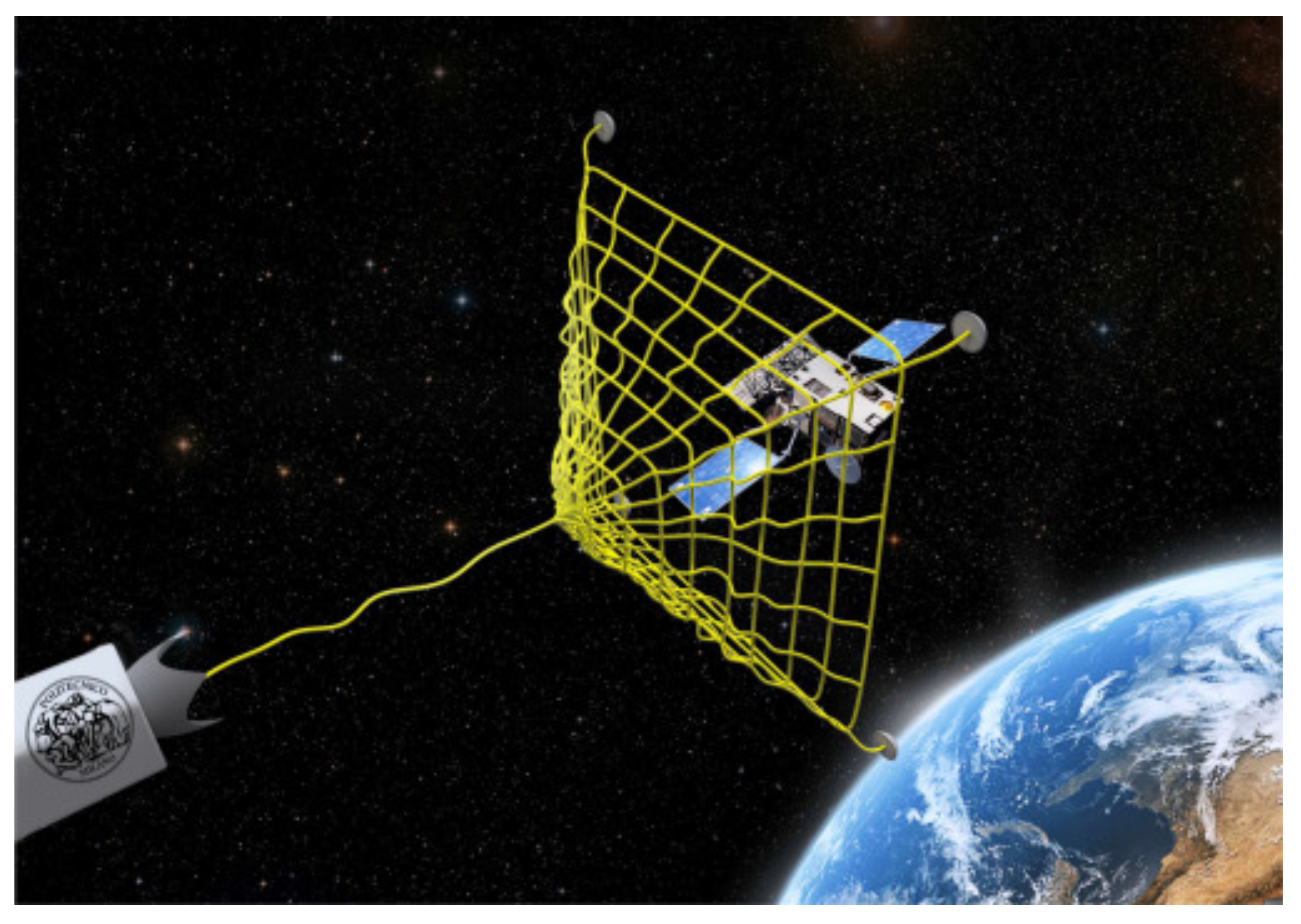
2.6.4. Flexible Connection Capturing Methods

Flexible connection capturing methods refer to techniques in which the end-effector and the satellite are linked by a flexible medium, typically a tether. Exampples of these methods include the tethered space robot (TSR), tethered space-tug (TST) or harpoon, and tethered net systems, all of which are considered part of this flexible connection approach [149].
Tether-Based Method: Tether-based methods represent an innovative approach to various space operations, particularly in the realm of space debris removal. These methods employ long, flexible cables or tethers, to connect spacecarft or components in orbit. Systems like the tethered space robot (TSR), tethered space-tug (TST) and tethered net have gained significant attention for their versatility and effectiveness in capturing and manipulating objects in space. These systems offer a broad operational range, enabling them to perform tasks such as in-orbit maintenance, repair, refueling, orbital maneuvering and space debris removal. The flexibility provided by the tether allows these systems to function across a wide operational workspace, making them well-suited for missions that involve accessing multiple targets or working in confined environments [86,99,150,151].
The tethered space robot (TSR) is an application of the tether-based method for space operations, consisting of a space platform, tether and gripper or manipulator. TSR systems represent an evolution of traditional robotic manipulators by positioning the manipulator on a lightweight, autonomous module, which is connected to an active spacecraft through an extended tether. TSR is highly promising for on-orbit servicing (OOS) tasks such as debris removal due to its flexibility and extensive operational range [86,152]. The use of tethers allows the TSR to extend the capture distance to several hundred meters, increasing platform security and reducing propellant consumption by minimizing the need for close-proximity maneuvers. However, managing the tether’s trajectory presents a significant challenge, requiring sophisticated flight control techniques such as coordination of gripper thrusts and tether tension control [153].
In a typical TSR mission (as shown in Figure 33), the robot approaches space debris, with the gripper advancing toward the capture point to physically secure the debris. Once captured, the debris is towed to a disposal orbit by the spacecraft’s thrust system. The flexibility and length of the tether enable the TSR to cover a large operational area, making it effective for missions involving multiple targets or tasks requiring a broad range of motion [151,154]. However, tether-induced oscillations must be managed carefully to prevent destabilization. Despite these complexities, TSR systems hold considerable promise for future on-orbit servicing missions due to their flexibility, portability, operational radius and inherent safety. Challenges such as visual servoing, coordinated orbit and attitude control, post-capture control, detumbling and towing operations need to be overcome to optimize TSR performance [155].
A notable TSR example is the ROGER (Robotic Geostationary Orbit Restorer) project, sponsored by ESA, designed to address space debris accumulation in geostationary orbit (GEO). ROGER uses a specialized satellite to capture non-functional or end-of-life satellites and transfer them to a graveyard orbit. The satellite employs sensors for rendezvous, inspection and capture, utilizing a net or tether–gripper system to secure the target satellite. After capture, ROGER stabilizes the debris and performs a transfer maneuver to safely dispose of it in a designated orbit. This project introduces a commercial, allowing satellite operators to extend asset life by outsourcing the disposal task to ROGER, adhering to space debris mitigation guidelines while maximizing satellite revenue [151].
The tethered space tug (TST) is a practical solution for the removal large space debris using a harpoon mechanism to capture targets from significant distances [156]. The harpoon system operates at high velocities (up to 20 m/s) with remarkable accuracy and has been rigorously tested in ground simulations, providing a reliable foundation for its potential use in space [157].
As illustrated in Figure 34, the harpoon mechanism is equipped with barbs at its tip, designed to penetrate and securely grasp large debris objects. Once captured, the debris can be towed by the chaser satellite, which is connected to the harpoon via a tether, for either re-entry into Earth’s atmosphere or transfer to a designated graveyard orbit. This method is valued for its low mass, high reliability and robustness to various target properties [75,158]. Its compatibility with different target shapes, allowance for a significant stand-off distance and the fact that no specific grappling point on the debris is required further enhance its appeal. However, there are some challenges associated with this approach: the impact of the harpoon can create additional smaller debris, potentially worsening the space debris problem. Furthermore, if the target is spinning or has a thick shell, the harpoon may ricochet, preventing successful capture [159].
A typical operation involving a tethered space tug (TST) proceeds through several phases: launching the space tug into orbit, conducting orbital phasing and rendezvous with the debris, employing the harpoon mechanism to capture the debris, stabilizing and orienting the debris, performing a controlled thruster burn and finally de-orbiting the debris or transferring it to a designated graveyard orbit [156].
One of the most promising methods for capturing large debris in orbit involves the use of tether-net [160], named the Net-capture method. The flexible connection tether net capturing method allows for the capture of objects without needing to pinpoint a specific location on the debris. The process of capturing space debris using a net involves three essential steps: deploying the net, capturing the target and de-orbiting the debris [161].
In the net deployment phase, flying weights are attached to the corners of the net, which are then propelled by a spring system known as the “net gun”. As the net is deployed, these flying weights expand the net, allowing it to wrap around the targeted debris [162]. As illustrated in Figure 35, the removal of a defunct satellite from low Earth orbit (LEO) using a net begins with the launch of a chaser satellite into the same orbit as the target. When the chaser satellite reaches an appropriate distance from the target, a net gun installed on the chaser fires the net to capture the target. Since most targets are tumbling, the chaser first de-tumbles the target before sending it back to Earth to burn up. After completing this process, the chaser maneuvers itself to target another piece of debris for removal. Once the debris is securely captured, the final step involves de-orbiting the debris [162,163].
Among these methods, the tethered-net capturing technique stands out as particularly promising due to its several advantages. These include (i) the capability to capture debris of various shapes and sizes, (ii) the ability to capture debris even when the chaser satellite is positioned at a considerable distance from the target, (iii) cost-effectiveness, (iv) reduced weight and volume, (v) compliance with the configuration and tumbling state of the target and (vi) the ability to capture debris at a safe distance from the chaser spacecraft [160,161,162,164].
Given the numerous advantages of the net capturing method compared to other approaches, Section 6 of this review is dedicated to a comprehensive exploration of this technique, from a mechanics perspective. It includes subsections on the available numerical approaches for the modeling of net dynamics, on the debris–net contact dynamics. Furthermore, both numerical and experimental results for net-based space debris removal are presented.

2.7. Self-Eating Satellite

The Self-Eating Satellite concept, often referred to as "eater", has been proposed as an innovative solution to the growing issue of space debris. These satellites are envisioned to be equipped with mechanisms that enable them to dismantle themselves once their mission is completed, reducing the risk of contributing to the accumulation of debris in orbit. Inspired by self-replicating systems, the goal of this technology is to provide a controlled, autonomous way of deconstructing the satellite, thereby ensuring a sustainable approach to space operations. Although this concept holds promise for mitigating space debris, it remains in the theoretical stage. No self-eating satellites have been developed or launched as of now. The involved challenges are both technical and ethical, including the complexity of designing systems capable of autonomous self-deconstruction in the harsh space environment. Moreover, the impact of such systems on future space operations and the long-term safety of orbital environments has yet to be fully assessed. Nonetheless, as space technology continues to advance, this idea may evolve into a feasible method for addressing the pressing issue of space debris management [165,166].

3. Design Parameters for Debris Removal Systems

To design an efficient debris removal system, it is important to understand the physical properties (such as size, mass and average cross-section area) of the debris. The raw data related to physical properties can be found in the ESA Database and Information System Characterising Objects in Space (DISCOS) [167]. The probability distribution of the size (depth, height and length) of debris is present in Figure 36a. The PDF of height and depth shows a similar trend, with maximum probability at around 6 m and some smaller peaks around 1, 4, 8 and 15 m, whereas the probability distribution of length shows that the most probable length of debris is around 2 m. Thus, from the overall analysis of the PDFs of depth, height and length, we can conclude that the most probable size of debris is around 2 m in length, 6 m in depth and 6 m in height. The maximum probability of size with different orientations ranges between 0 and 7 m. It has also been observed (Figure 36a) that the probability of large-sized debris (>20 m) is negligible. Thus, for the efficient design of debris removal systems, we need to focus on a system that can easily capture debris with a size of under 20 m. Extra attention is needed to design an efficient system that can capture smaller debris ranging from 0 to 7 m.
The distribution of mass of debris in the Earth’s orbit is calculated using the database available on ESA DISCOSweb and presented in Figure 36b. The probability distribution of mass shows that debris with a mass of less than 1 ton is more probable, with a decremented probability of 2, 4, 3 and 5 tons. The probability of a mass of debris greater than 6 tons is negligible. Thus, the debris-capturing system must be designed, taking into consideration that debris with a mass of less than 1 ton is more probable, and it should be able to handle debris with a mass in the range of 0–6 tons.
The cross-sectional area of the debris is also one of the important parameters for the debris capturing and removal system. Therefore, we analyzed the probability distribution of the area cross-section of the debris in Earth’s orbit and showed it in Figure 36c. Approximately 21,000 datasets are used to calculate the probability distribution function. Based on our results, the probability distribution of the cross-sectional area of debris suggests that debris with a cross-sectional area of less than 10 m2 is most probable. However, we also found PDF local maxima near 18 and 28 m2. The probability is diminishing for large debris exceeding a cross-sectional area of 50 m2. According to our analysis, the debris-capturing system should be able to seize debris with a cross-sectional area of less than 50 m2, with a particular emphasis on debris with the cross-sectional area of less than 10 m2.
Figure 37a depicts the probability distribution of an object angle of inclination in the Earth’s orbit. Based on the PDF of the inclination angle of the debris, it was found that the PDF represents most of the distribution of the inclination angle of the debris around 45 to 105 degrees, with a peak at about 50 degrees, demonstrating it as a most probable angle of inclination.
Figure 36b and Figure 37c show PDF plots of the debris position at apogee and perigee in kilometers. According to our results, the probability distribution of the debris position ranges from 0 to 2000 km at apogee and from 0 to 1500 km at perigee. Most of the debris was found around 200 km from both the apogee and perigee, with the second most probable region for debris being around 800 km and 700 km from the apogee and perigee, respectively. For computing these probability distribution functions, around 32,000 datasets were considered. Furthermore, the probability distribution of the velocity of the object at apogee and perigee is presented in Figure 38a. The velocity distribution of objects at apogee and perigee shows that the most probable velocities of the debris at apogee and perigee are 7700 m/s and 7800 m/s, respectively. It has also been observed that a velocity of 3000 m/s is the second most probable velocity in both apogee and perigee. Overall, from the PDF plots, it has been seen that the probabilities of velocities at apogee and perigee are approximately the same.
In order to compute the kinetic energies (K.E.) of the objects at apogee and perigee, information related to the mass and altitude of the objects at apogee and perigee is needed. This information is present in two different databases, i.e., in ESA DISCOSweb and space-track. Therefore, the databases were first merged based on the cataloged ID. Then, the kinetic energies (in joules) were computed by using velocities and masses obtained from the merged database. Furthermore, the probability distribution function of kinetic energies at apogee and perigee are computed on a logarithmic scale ( log 10 ). The probability distribution of the kinetic energy of objects at the apogee and perigee is presented in Figure 38b. The most probable kinetic energies at the apogee and perigee range from around 10 9 to 10 10 Joules.
The joint probability of mass and average area of cross-section of debris is presented in Figure 39. According to the plot, the most probable distributions of debris for the mass and average cross-section are around 0–5 tons and 0–40 m2, respectively.
The parameters discussed above, including size, mass, cross-sectional area, altitude, inclination and kinetic energies of cataloged debris, will be useful for the design and development of an efficient debris removal system.

4. Mitigation Strategies

Constraining the growth of space debris in order to preserve Earth’s orbital space, particularly LEO, is an urgent challenge for space agencies [170,171]. The launch activities and operational practices have resulted in the increased amount of debris in the Earth’s orbit, creating a problem for other functional satellites and spacecraft. Measures such as de-orbiting non-functional satellites should be taken to reduce collision rates and constrain the amount of debris [172]. The development of analytical and numerical models for high-speed collision testing is a good route to reduce the potential risk of damage and fragmentation of satellites. The inclusion of parameters such as velocity, mass, shape, size and area of cross-section of debris in these models allows us to produce more accurate and useful information for testing damage mitigation techniques [173]. These numerical and analytical models would also be helpful for the design and development of protective shields for satellites.
Beyond technical measures, international coordination has led to the establishment of guidelines aimed at ensuring the sustainability of future space activities. For instance, the Inter-Agency Space Debris Coordination Committee (IADC) recommends that satellites operating in LEO should de-orbit within 25 years after mission completion. Controlled re-entry maneuvers, such as those steering large debris objects into the atmosphere at steep angles, help ensure that debris falls into sparsely populated areas, such as the South Pacific Ocean Uninhabited Area (SPOUA), minimizing risks to human life [174,175].
To mitigate space debris, there are two primary categories of strategies: short-term and long-term risk reduction methods [173]. Short-term strategies emphasize collision avoidance maneuvers, adjusting a satellite’s trajectory to prevent collisions and further debris generation. However, these methods are temporary and do not address the long-term risk. Long-term strategies include de-orbiting non-operational satellites, active debris removal and transferring objects to less congested orbits [173,176].
Numerous studies have been conducted on how to further reduce collision risks and limit the growth of space debris. Among these are efforts focused on de-orbiting satellites using drag augmentation systems (DASs), such as deployable drag sails [95] or electromagnetic tethers [177]. These systems, especially suited for small satellites, operate by increasing the surface area exposed to atmospheric drag, accelerating orbital decay, and thus shortening the satellite’s de-orbiting timeline. This process reduces the likelihood of future collisions, promoting sustainable use of orbital space [95,101,177].
Space agencies and companies are also exploring innovative debris capture methods. Examples include the European Space Agency’s “e.Deorbit” project [178], the “Robotic Geostationary Orbit Restorer” (ROGER) [179] and the "Junk Hunter" program proposed by the Japan Aerospace Exploration Agency (JAXA) [180]. Among these approaches, the net capture method stands out due to its advantages. Nets, composed of elastic materials, can capture debris of various shapes and sizes, requiring relatively low accuracy in targeting. Their adaptability and cost-effectiveness make them suitable for capturing non-uniform objects at a safe distance from the uncontrolled target [113]. In 2018, the RemoveDebris mission marked the first successful in-orbit demonstration of two key technologies designed for capturing large space debris: a net and a harpoon. During the mission, a net was deployed to capture a CubeSat that had been intentionally released from the main spacecraft as a test target. Once the CubeSat reached a distance of 5 m, it was captured by the net at approximately 7 m, securing it before de-orbiting. The harpoon, in turn, was tested by targeting a material representative of old satellite structures, which was mounted at the end of a deployable boom. Both capture technologies were successfully demonstrated [160,181].
In addition to long-term debris removal strategies, there are tactical approaches aimed at preventing immediate collisions between large debris objects. While these large objects are not frequent collision candidates, they pose significant risks due to the vast amounts of debris generated in the event of a collision. For this reason, large debris traffic management encompasses two primary approaches: Active Debris Removal (ADR) for strategic, long-term debris collection, and Just-in-time Collision Avoidance (JCA), a tactical method focused on preventing imminent collisions [182,183].
The Just-in-Time Collision Avoidance (JCA) method offers a proactive approach to prevent collisions between large, non-maneuverable objects. Although such collisions are rare, when they do occur, they generate sustantial quantities of debris, significantly increasing the number of uncontrolled objects in orbit. The JCA strategy involves applying a small velocity change ( Δ V ) to one of the objects at risk, causing a slight orbital shift. Over time, this small change results in a gradual increase in the miss distance at the predicted conjunction point [184].
As shown in Figure 40, two large debris objects, A and B, are identified as having a collision probability exceeding a certain threshold. Their orbits are precisely calculated several days before the predicted collision by entities like the Joint Space Operations Center (JSpOC), with data continuously refined through radar observations. To prevent the collision and the creation of numerous additional debris fragments, a JCA operation is authorized by an international body.
A sounding rocket is launched from one of several globally distributed bases, intended to deflect one of the debris objects multiple orbits before the anticipated collision. These bases, typically three or four, are strategically positioned at high northern latitudes—such as Kodiak Island, Kiruna, Andøya or Northern Russia—to maximize interaction opportunities with the target. The sounding rocket, which may be partially or fully reusable, is launched either from the ground or airborne. A gas and particles generator derived from a Solid Rocket Motor (SRM) is mounted on the rocket’s upper stage, which is then aimed in the anti-flight direction. This generator fires at apogee, near the debris trajectory, just before the debris’ transit time. The timing and direction of the firing are optimized to achieve the greatest deflection efficiency. Preliminary studies suggest that the necessary trajectory and accuracy for operation are achievable. After firing, the generator follows a sub-orbital trajectory and falls back to Earth, with potential for recovery and reuse.
The velocity change δ V imparted to the debris alters its semi-major axis and orbital period δ T . Over time, this perturbation results in the desired miss distance Δ L , as described by the Clohessy–Wiltshire equations:
δ T = 3 T δ V V ,
leading to:
Δ L = 3 T δ V .
For instance, at an altitude of 800 km, achieving a miss distance Δ L of 1 km with a JCA operation conducted 24 h before the predicted collision requires a δ V of 3.8 mm/s. These calculations have been validated by CNES and Bertin orbital simulators [183]. Reducing the response time or increasing the miss distance would proportionally increase the necessary δ V . This relationship is indeed approximately linear, so a Δ V of 1 cm/s imparted 12 h before conjunction results in a miss distance of 1.5 km [184,185].
A critical assumption for JCA effectiveness is that the accuracy of the debris ephemerides must be improved by one or two orders of magnitude over current observational capabilities. This improvement is essential to ensure the JCA system’s success [184,185].
Several alternative methods are under study, including laser-based momentum transfer, where laser ground stations use light pressure to impart the required Δ V ; orbital tungsten dust clouds designed to clear entire orbital regions of small debris; vapor clouds launched on suborbital trajectories to prevent debris collisions; and orbital laser stations that employ high-fluence, short-pulse lasers to vaporize the debris surface, generating a recoil effect [184,185,186].
In the next section, we will focus on the dynamics of the net capturing system, which are considered one of the most promising technologies for effective space debris capture. Finally, it is stressed that the International Academy of Astronautics (IAA) has conducted multiple studies on the current status and stability of space debris to address possibilities for space traffic management and mitigation of debris creation [187]. According to the most recent IAA reports, the need for continued action on space debris mitigation remains critical. Mitigation strategies, such as limiting the orbital lifetime of upper stages and transferring satellites to disposal orbits after mission completion, play a significant role in preventing debris accumulation in key orbits like LEO and GEO.

5. Net Capturing Systems: Modeling, Experiments and Space Missions

5.1. Modeling of Net Dynamics

The dynamics of a net capturing system involves several length scales, from the interaction processes at the nano- to micro-scale, determining macroscopic contact properties such as the friction, to the net compliant body dynamics, determining the debris wrapping dynamics, and to the whole system multi-body dynamics, determining the center of mass trajectory during the entire capturing process.
The contact dynamics of flexible nets are typically simulated recurring to a lumped formulation of the system dynamics, obtained either by the finite element method or simply by the application of linear momentum conservation to a simplified mass-spring-damper representation of the net. Clearly, the more degrees of freedom involved in the discretization process, the larger the computational complexity of the simulation [188]. In the following, the fundamentals equations describing the dynamics of the net as well as the adopted contact mechanics’ numerical implementation will be presented and discussed, accordingly to the recent literature.
In the simplified mass-spring-dashpot model, the net is represented, e.g., by a lattice of masses connected with spring-dashpot elements, as shown in Figure 41 [162]. The deployment of the net is performed by shooting four bullets (mass points) attached to the corners of the net [162]. The mechanical response of the cable is typically modeled with a Kelvin–Voigt viscoelastic scheme [189], sufficiently accurate for simulating large-scale flexible nets [190]. However, because of the inherent geometrical and material characteristics of the cable elements, the latter are unable to sustain compression, resulting in internal (tension) forces generated only upon cable elongation. This results in a Kelvin–Voigt model where the tension force f i j exerted between nodes i and j in a flexible net can be described as follows [161]:
f i j = f i j r ^ i j r i j > l 0 and f i j < 0 , 0 r i j l 0 or f i j > 0 ,
where r ^ i j is the unit direction vector of the two adjacent nodes of the segment [161,190]. f i j is given by
f i j = k ( r i j l 0 ) c r i j ˙ ,
where the relative distance and the relative velocity between the i th and j th nodes are r i j and r i j ˙ , respectively. The simplest elastic description of a cable would require the stiffness constant to be defined as k = EA / l 0 , where E is the modulus of elasticity, A is the cross-sectional area of the cable and l 0 the initial length [161,190]. The damping coefficient c of the cable material (liking the i th and j th nodes) can be expressed in terms of a damping factor as follows:
c i j = 2 ζ m i j k ,
where ζ is the damping ratio, and m i j is given by the m i m j / m i + m j lumped mass.
Before launching the net, the chaser satellite is supposed to move toward the target in an along-track direction [161,191], as depicted in Figure 42.
The inertial reference frame for the net capture dynamics is centered on the Earth and the local reference frame is centered on the center of mass of the net launch system [161,191]. The absolute position of mass points in the inertial reference frame can be expressed as follows [161]:
r i e = r P + R o r i ,
where in the inertial frame, R o is the rotation matrix which transform the position vector r i from the local system into the inertial system and r i e represents the absolute position of the i th node in the inertial frame. Finally, the discretized equation of motion is expressed as follows [161,191]:
m i d r i e ˙ dt = j = 1 N i R o f i j + s = 1 M i f i s e + g i .
In Equation (7), N i is the number of neighboring cables linked to the i th node, f i j is the force acting on the i th node by the j th connected cable; M i represents the number of external forces on the i th node. The sum of external forces, such as aerodynamic drag or solar radiation pressure, is represented by f i s e . The micro-gravitational force g i on the i th node is given by [161,191]
g i = GMm i r i e | r i e | 3 ,
where GM is the gravitational coefficient of the Earth [161,191].
An alternative modeling approach can be achieved with a non-linear finite element description of net dynamics in the absolute nodal coordinates (ancf method [192]). The ancf approach can be used to describe the flexibility of the net with fewer elements as well as adopting more complex cable rheological description [150,193]. As shown in Figure 43, there is one element (cable) between the two nodes [193].
The position of any point along the deformed cable element can be represented through the use of the shape function S , combined with the coordinates of the two nodes, as [193,194]
r = Se = [ S 1 I , S 2 I , S 3 I , S 4 I ] [ e 1 , e 2 ] T ,
where I denotes a 3 × 3 identity matrix, and e i (for i = 1 , 2 ) represents the absolute nodal coordinates at x = 0 and x = l 0 . Here, x specifies the local coordinate of an arbitrary point on the element, and l 0 indicates the initial length of the cable element [193,194]. In terms of nodal coordinates (see Equation (10)), r i and r i , x are the element’s global displacements and slope [193,194,194]:
e i = [ r i , r i , x ] ; r i , x = r i x .
The shape functions S i are defined as
S 1 = 1 3 ξ 2 + 2 ξ 3 , S 2 = l 0 ( ξ 2 ξ 2 + ξ 3 ) , S 3 = 3 ξ 2 2 ξ 3 , S 4 = l 0 ( ξ 2 + ξ 3 ) ,
where ξ = x / l 0 , and x is the coordinate of any point on the element [193,194]. Finally, in order to derive the system of motion equations for the tethered net, one must use the principle of virtual work and introduce Lagrange multipliers [193]:
M b 0 Φ b T 0 M e Φ e T Φ b Φ e 0 q ¨ b e ¨ λ = Q b Q e Q ,
where the mass matrix of bullets and the external forces on the bullets are given by M b and Q b , respectively. The term M e corresponds to a constant ANCF mass matrix, and Q e is the generalized force associated with the absolute nodal coordinates e . Here, Q e represents the external forces plus the elastic forces. The Lagrange multipliers are defined by λ ; the Jacobi matrix of the constraint associated with the absolute nodal coordinates is Φ e ; Φ b represents the constraints coupled by the bullet masses and the cable elements; Q is a velocity vector of a quadratic nature obtained by performing a second differentiation of the constraint equations in terms of time [162,193].

5.2. Debris-Net Contact Dynamics

The contact dynamics in the debris vs net interaction does play a central role in the whole dynamic process. Due to the irregular geometries of the interacting objects, classical analytical theories of contact mechanics (such as Hertz or Westergaard contact mechanics) cannot be applied to the debris/net interaction, resulting in the lack of fundamental studies on how, e.g., adhesion and friction would improve the capturing ability of nets. Hence, the contact mechanics has been solved only numerically, with emphasis on the contact detection methods and on the implementation of the contact inequalities in the net dynamics (with approaches such as penalty-based and impulse-based methods) [161,190,195,196,197]. In particular, the contact detection phase employs specific algorithms for the detection and monitoring of collisions, utilizing either the line–line collision detection algorithm [196] or the axis-aligned bounding box (AABB) method [161], to cite a few. The numerical implementation of the contact inequalities (Signorini’s conditions) is typically obtained by employing two distinct approaches, namely the penalty-based and the impulse-based method; however, contact detection is the same for both models [75,161,162,191,198,199].
In the context of debris-capturing simulations, contact detection is a critical process conducted at every numerical iteration step. This monitoring allows for the immediate identification of any contact events as they occur. The detection not only confirms the occurrence of a contact or collision but also provides the necessary groundwork for an appropriate response to these events. This ensures a thorough and accurate representation of interactions within the simulation, essential for realistic and effective modeling [161,196,197]. As anticipated, specific methods are adopted for contact detection in the contact dynamics of the net systems, including the line–line collision detection algorithm [196] and the axis-aligned bounding box (AABB) method [161,193].
In the case of line–line collision detection, the interaction between the net and the target is determined by measuring the distance between the net node and the target center, which is used to assess their proximity [196]. A collision is considered to have occurred when the following condition is met:
δ = ( R i + R o b j ) | x i x o b j | > 0 .
In the inequality above, δ represents the penetration depth. R i and R o b j denote the radii of the net i-th node and the object, respectively. x i and x o b j are the actual position vectors of the net i-th node and the object center, respectively. If the calculated δ value is positive, it indicates that contact has occurred between the net and the target [196].
The axis-aligned bounding box method utilizes bounding boxes that are aligned with the coordinate axes. This alignment makes the boxes independent of an object’s orientation, eliminating the need for rotation adjustments during simulation steps. Such a design significantly enhances the method’s efficiency in detecting contacts. The AABB algorithm is structured in two tiers to optimize computational performance [198,200]. At the first tier, the net and the target are each enclosed within their bounding boxes, labeled N and T, respectively. This initial stage of contact detection involves only these two boxes (as illustrated in Figure 44a). Early in the net deployment phase, when the net is still distant from the target, this tier predominantly governs the simulation to enhance computational efficiency. The second tier starts when the bounding boxes N and T cross each other (as shown in Figure 44b). Here, each net node is scrutinized for potential contact with the target by measuring the distance d between the node and the target. If this distance is less than a pre-defined threshold, a corresponding contact response is triggered at that node. This two-tiers approach in the AABB method effectively balances computational efficiency with accurate contact detection [161,198].
The nature of the contact response depends on the contact modeling method selected: Penalty-based or impulse-based. In the penalty-based approach, a contact force is calculated at the point of contact upon detection. Conversely, in the impulse-based method, the contact impulse and resulting velocity change are determined, which are then passed to the net equations of motion. In the net-contact dynamics, a net is modeled as multiple mass points linked with spring-damper elements in a specific pattern. Therefore, net contact with a target can be thought of as multiple mass points contacting the target surfaces. The mass points are considered to move outside the space of the target and are forbidden to penetrate it. Thus, according to this constraint, net vs debris contact can be framed within an inequality constraint problem, thus approached with a penalty-based method. The latter is typically used to solve optimization with inequality constraints [190]. In a generic optimization problem, the inequality constraint can be expressed as [193]
Minimize f ( x ) , subjected to c ( x ) 0 ,
where f ( x ) and c ( x ) are the objective function and constraint equation, respectively. The inequality constraint optimization can be transformed into an unconstrained optimization with [193]
Minimize f ( x ) + μ min { 0 , c ( x ) } , subject to x R n ,
where μ min { 0 , c ( x ) } is defined as the penalty function. When the point is not in contact with the target surface, c ( x ) 0 , the constraint equation is min { 0 , c ( x ) } = 0 . However, when the point penetrates the target surface, c ( x ) < 0 . The penalty force, here the contact force energy μ c ( x ) , is added to the objective function f ( x ) to push the point away from the surface and prevent further penetration [193]. This definition considers the penalty function μ min { 0 , c ( x ) } to be a function of penetration depth c ( x ) . When two elastic bodies come into contact, the colliding bodies deform, and the contact force is expressed as a function of deformation. In simulations of a contact scenario, the deformation of the contact can be parameterized according to the depth of penetration between the colliding bodies. In the penalty-based method, the reaction force is calculated based on the depth of penetration: the deeper the penetration, the higher the penalty [193].
In the impulse-based method, the impulse caused by the contact is calculated instead of the contact force. Thus, in this method, the change in the linear momentum is computed because of the contact [191]. Virtual reality and gaming environments typically use impulse-based methods for the contact between two separate bodies [191]. The basic idea of impulse-based simulation is that any contact between bodies is modeled by collisions at the contact points [201]. The net is again discretized into mass points that are connected in a specific pattern. Consequently, a net encountering a target can be generically considered as multiple mass points of contact with the target object [191]. Shan and colleagues were the first to apply the impulse-based dynamic model for the purpose of capturing space debris using a net [161]. An impact is a complex event influenced by a number of physical factors; however, it can be approximately summarized in two stages: Compression and restitution. Compression begins at contact and ends when the bodies separate, namely restitution stage. The amount of recovered deformation after (compressive) collision, thus the amount of energy loss, allows for the impacts to be typically categorized under three scenarios, namely perfectly elastic, perfectly plastic, partially elastic (or partially plastic) [202]. The coefficient of restitution, denoted by e r , makes it possible to quantify the amount of dissipated energy upon contact, thus the variation in linear momentum, with the following relation:
e r = v r + v r .
In Equation (16), with 0 < e r < 1 , the superscripts ‘−’ and ‘+’ indicate the state of the objects before and after the contact, respectively. More specifically, v r + represents the relative velocity of two objects after contact, while v r represents the relative velocity before contact. A value of e r = 0 corresponds to a completely inelastic contact, where v r + = 0 . On the other hand, an e r = 1 value of 1 implies v r + = v r , indicating a perfectly elastic collision. The restitution coefficient varies based on the materials of the two interacting solids [161,198].
As illustrated in Figure 45, when a net contacts a target, it can be modeled as multiple mass points interacting with a single object. This approach excludes the cables from the contact detection process. Consider n mass points making contact with an object, which is characterized by its center of mass, labeled as O. The velocities of these mass points and the object’s velocity are denoted as v i (for i = 1 to n) and v O , respectively. The object’s angular velocity is represented by ω O . When dealing with a target of irregular shape, it can be modeled as a polyhedron for simplicity. The direction normal to the contact surface is given by n i , and the mass and impulse magnitude at the i -th contact point are m i and j i , respectively. It is important to note that both linear and angular momentum remain conserved during the contact process [161,198]:
m O v O + ( m i v i ) = m O v O + + ( m i v i + ) , I O ( ω O + ω O ) = ( r i × j i n i ) .
Following the interaction, the i-th mass point’s velocity after contact is given by the folllowing formula:
v i + = v i + j i n i / m i .
After contact, the velocities of the target, encompassing both linear and angular components, are defined as
v O + = v O + ( j i n 1 + j 2 n 2 + + j k n k ) / m O , ω O + = ω O + I O 1 ( r 1 × j 1 n 1 + r 2 × j 2 n 2 + + r k × j k n k ) .
In Equation (19), the contact impulse vector j is depicted as an undetermined vector and is expressed as
j = [ j 1 , j 2 , , j k ] T .
To streamline the expression, the normal vector N is introduced as
N = [ n 1 , n 2 , , n k ] T
and Σ rk is delineated through the expression provided below:
Σ rk = i = 1 k ( r i × j i n i ) .
Therefore, Equation (19) may be reformulated as
v O + = v O + N T j / m O , ω O + = ω O + I O 1 Σ rk .
Applying the principle of impulse conservation and factoring in the coefficient of restitution denoted by e r , one can infer the after-contact relative velocities along the direction normal to the contact surfaces as
( e r + 1 ) v r 1 = n 1 · [ j 1 n 1 / m 1 + N T j / m O + ( I O 1 Σ rk ) × r 1 ] , ( e r + 1 ) v r 2 = n 2 · [ j 2 n 2 / m 2 + N T j / m O + ( I O 1 Σ rk ) × r 2 ] , ( e r + 1 ) v r k = n k · [ j k n k / m k + N T j / m O + ( I O 1 Σ rk ) × r k ] .
The left-hand side of the expression can be reformulated using the vector notation v :
v = ( e r + 1 ) [ v r 1 , v r 2 , , v r k ] T .
For greater simplicity in the expression of Equation (24), it can be restructured as follows:
u i j k = ( I O 1 ( r i × n j ) ) × r k .
Thus, the matrix coefficient M is acquired from Equation (24):
M = 1 m 1 + 1 m O + n 1 · u 111 n 1 · n 2 m O + n 1 · u 221 n 1 · n k m O + n 1 · u k k 1 n 2 · n 1 m O + n 2 · u 112 1 m 2 + 1 m O + n 2 · u 222 n 2 · n k m O + n 2 · u k k 2 n k · n 1 m O + n k · u 11 k 1 m k + 1 m O + n k · u k k k .
The formula presented in Equation (24) can be restructured as
v = M j .
Therefore, the impulse vector corresponding to each contact point can be inferred from
j = M 1 v .
By calculating the impulse at each contact point j , the after-contact velocities can then be ascertained with the aid of Equations (18) and (19) [161,198].

5.3. Numerical and Experimental Results for Space Debris Capture Systems

The literature reports several numerical studies targeted at the prediction of the net dynamics during the contact and capture of an object. Most of the computational models are based either on the mass-spring-damper description of the net (Figure 46a) or the ANCF (Figure 46b) models [161,193,203], discussed earlier. Moreover, it has been demonstrated that both the penalty-based and the impulse-based methods are effective in the numerical modeling of the net vs object contact [150,161].
Botta et al. [197] presented a numerical study to gain insight into the dynamics of space debris capture, with particular focus on the chaser, capture net and closure mechanism. The multi-body dynamics simulation platform Vortex Dynamics was used to run the simulations. Several net models were implemented, such as a standard lumped parameter model, an augmented lumped parameter model and a cable-based model. The model with standard lumped parameters is shown in Figure 47a. The mass properties of the net are represented by small spherical rigid bodies at the knots of the net, while the axial stiffness and damping properties are represented by massless springs and dampers between the small rigid bodies (nodes). In the augmented lumped parameter model, additional linear and torsional springs and dampers were added to describe the bending stiffness of the cables of the net. In the cable-based model, depicted in Figure 47b, it distributes the net’s mass along its threads, which are depicted as slender rigid bodies. These bodies are interconnected through relaxed prismatic joints [197].
Moreover, a library featuring several realistic targets was developed, encompassing the Apollo spacecraft, the second stage of Zenit-2 rockets, Envisat and a small asteroid akin to Bennu. The scaled-down model of asteroid Bennu is shown in Figure 48. Based on the scaled 3D model of Bennu, a convex mesh collision geometry was added [197]. The snapshots of the capture sequence of asteroid Bennu, as depicted in Figure 49, demonstrate the effectiveness of the capture mechanism. By 23 s (Figure 49b), the main tether has engaged the lock, the net has enveloped the asteroid and the closing mechanism is operational. Closure is nearly complete by 26 s (Figure 49c) and fully confirmed by 30 s (Figure 49d). From that point onward, the simulation consistently shows that the asteroid remains securely captured by the net (Figure 49e,f).
The literature also focuses on the geometry of the net, e.g., inspired by nature and designed as a spider web, both with finite element and experimental analysis of collision dynamics [164,204]. In a recent finite element study [164], the collision of objects with a stationary web is simulated. Several cases were computed and the impact of objects leading to failure or rupture of the web was reported. Interestingly, the study shows that spiral webs have better strength compared to radial webs, shedding light on the key role of the adopted net geometry. Furthermore, based on the dynamics of the simulations, it has been shown that a rotating web, unlike a non-rotating web, cannot completely capture objects. Indeed, the wrapping of the objects depends strongly on their shape, their number, as well as on the relative speed of the web, the angular velocity of the spin-stabilized web and the direction of its spin [164]. The wrapping ability of a net is strongly affected by its geometry, as reported in [204], where the authors discuss increasing the net flexibility with respect to traditional quadrilateral webs thanks to the adoption of bio-inspired geometries. In particular, it has been observed that the bio-inspired octagonal webs have higher dissipation performance, high tolerance ability and significant mechanical properties compared with the quadrilateral webs, leading to higher capturing performance (see the deformation of two web configurations in Figure 50 [204]).
Fundamental experimental studies were also conducted to understand the debris capture dynamics using flexible nets. Figure 51 shows the ground verification experimental setup for the debris capture device. This device consists of a flexible net with magnetic masses connected at corners, a central rigid body, a central shaft, transmission elements, a variable-speed motor, and other components [204]. The net is made up of polyethylene fibers woven in an octagonal shape. The polyethylene fiber segment has a diameter of 0.3 mm, and the diagonal diameter of the webs is 1.0 m. Magnets are used to make the mass blocks at the corners of the net, and each magnetic mass weighs five grams [204]. The collision process between the flexible web and the target is reported in Figure 52. The results show that the flexible web collided with the target body and wrapped it. Due to the presence of gravity, the shell-nosing condition is slightly different on Earth and ground testing also reported the weaving defects of the flexible web. Overall, the authors concluded that the bionic-designed (cobweb-like) flexible capture device can be an effective debris-capture system [204].
In another experiment for testing a debris-capturing system, a testbed is established in a laboratory with a height of 4m. The testbed consists of a net and tether assembly (see in Figure 53a), a model of debris (a helium blimp, see in Figure 53b), a frame that holds the net in an expandable state, a mechanism that raises or lowers the net and tether assembly and a release mechanism to drop the weights attached to the corners of the net. As shown in Figure 54a, the experiment begins with the net in an expanded state, ready for the debris capture process. This figure illustrates the initial setup before deployment, highlighting the positioning of the net with the target debris. In Figure 54b, the deployment process of the net is depicted. This figure shows the actuation mechanism where the corner weights are released. The dynamics of the corner weights falling due to gravity are clearly visible, demonstrating the initial phase of the debris capture. Figure 54c captures the stage when the falling corner weights make contact with the debris. This crucial interaction is shown, highlighting how the net begins to adapt its shape to enclose the target debris, which is a key part of the capture process. Finally, Figure 54d presents the final stage of the debris capture mechanism, where the net has fully enclosed the target debris. This figure demonstrates the successful containment of the debris, with the net completely wrapped around it, ensuring that the debris is securely captured.
The experimental demonstration shows the applicability of a net closure system which is a promising concept for the space debris removal system. The experimental testbed designed in this study is useful for the validation of the dynamics of the net capture system and, specifically, for the deployment of a net [205].
As part of the Clean Space Initiative, another experiment was conducted by SKA Polska under an ESA contract. The experiment used a tether-net capturing system to validate the debris capture mechanism of the scaled-down model of EVISAT. The experiment was conducted in a microgravity environment inside the Falcon-20 aircraft. The trajectory of the deployment of the net and the wrapping of the modeled debris was captured using two fast stereographic camera sets. The schematic of the net geometry is shown in Figure 55. In this experiment, two cases were tested, as seen in Figure 56. In the first case, a net with dimensions of 1 × 1 m, 10 cm mesh size, 1 mm nylon thread, knotted assembly, spacing 1.5 m and two different velocities of 1.5 m/s and 2.5 m/s (Figure 56) was considered. In the second case, a net with 1 × 1 m, 6 cm mesh size, 2 mm nylon thread, knotless assembly, spacing 1.5 m and two different velocities of 1.5 m/s and 2.5 m/s was considered [206].
The experimental setup with the thicker net 16 × 16 (second test case) is shown in Figure 57. During the experiment, 22 parabolic flights were carried out by Falcon 20 aircraft. Out of 22, in 20 parabolic flights, there was a successful target capture sequence that includes the following stage, the deployment and flowing of the net, net hitting and wrapping target and recording of the trajectory [206]. The experimental results show that the performance of thicker 16 × 16 net (second test case) was worse than the thin 10 × 10 net. The experimental results also validate the dynamics of the net capturing mechanism obtained from the simulation [206].

6. Preventive Steps

In 2021, the Inter-Agency Space Debris Coordination Committee (IADC) published the Space Debris Mitigation Guidelines (IADC-02-01 Rev. 3). These guidelines aim to prevent the creation of new space debris by recommending preventive measures in the design, operation and disposal of spacecraft. The guidelines focus on limiting debris released during normal operations, minimizing the potential for on-orbit breakups, ensuring safe post-mission disposal, and preventing on-orbit collisions in both LEO and GEO orbits.
It includes requirements for post-mission disposal in the geosynchronous Earth orbit (GEO) region, specifying that spacecraft and launch vehicle stages must be maneuvered to orbits that remain outside the protected region for at least 100 years. In addition, the guidelines provide enhanced measures to prevent accidental on-orbit breakups, focusing on minimizing stored energy such as venting propellants, deactivating batteries, and other forms of passivation to avoid explosions after the mission has ended. It also addresses the risks associated with spacecraft re-entry, aiming to limit the human casualty risk to 1 in 10 k for any re-entry event and ensuring that debris falls in uninhabited areas when possible [207].
The IADC guidelines are widely accepted by space agencies and industries globally, and while not mandatory, they have been incorporated into the planning and operation of many space missions. Below is a summary of the IADC Space Debris Mitigation Guidelines:
  • Guideline 1: Limit debris released during normal operations.
  • Guideline 2: Minimize the potential break-ups during operational phases.
  • Guideline 3: Limit the probability of accidental collision in orbit.
  • Guideline 4: Avoid intentional destruction and other harmful activities.
  • Guideline 5: Minimize potential post-mission breakups resulting from stored energy.
  • Guideline 6: Limit the long-term presence of spacecraft and launch vehicle orbital stages in the LEO region after the end of their mission.
  • Guideline 7: Limit the long-term interference of spacecraft and launch vehicle orbital stages with the GEO region after the end of their mission.
These voluntary guidelines for the planning and operation of newly designed space missions, as well as for existing space missions where applicable, are not mandatory under international law. However, they have become widely accepted by many space agencies and organizations globally.
In 2001, the U.S. government created the Orbital Debris Mitigation Standard Practice (ODMSP) to address the increase in space debris in the Earth orbits. The objective of ODMSP is to prevent the creation of new and long-term space debris by controlling debris released during operations, minimizing the creation of new debris from accidental collisions or explosions, and selecting a safe flight profile and disposing of satellites after their mission [208]. It also states that spacecraft and rocket bodies must be designed in such a way to minimize the risk of debris creation during the operational phase [208,209].
The Federal Aviation Administration (FAA) also contributes to space debris mitigation efforts and has developed regulations for the U.S. launch industry. According to Title 14 of the Code of Federal Regulations (CFR), Part 415.39, “Safety at the End of Launch”, the FAA requires that the launch vehicle must fulfill specific safety standards to minimize debris creation [210]:
  • There is no unplanned physical contact between the payload and the vehicle or its components after payload separation.
  • Energy sources such as chemical, pressure and kinetic energy do not result in the fragmentation of the vehicle or its components, creating new debris.
  • Stored energy is removed by depleting residual fuel, venting any pressurized systems, and leaving batteries in a permanent discharge state.
In June 2004, the Federal Communications Commission (FCC) of the United States issued comprehensive regulations for orbital debris prevention. These regulations apply to both the licensing of non-U.S. satellites used to offer services in the U.S. and the licensing of U.S. commercial satellites. The regulations require disclosure of debris prevention strategies, including end-of-life measures, prior to authorization [211]. The required disclosures include the following:
  • Avoidance of collisions with other large objects during routine operations.
  • Post-mission disposal plans.
  • Debris control strategies during routine operations, including explosion prevention and spacecraft shielding to avoid collisions with small debris.

7. Discussion and Conclusions

The threat posed by today’s space activities is a direct result of the previous belief that “space” offered boundless opportunities for human endeavors. However, due to human interference, this issue has escalated into a critical problem that threatens the space environment. It is worth noting that only a few countries possess the capability to launch rockets or satellites into space. Nonetheless, the quantity of objects present in space has experienced a significant surge over the years due to various space activities, such as satellite launches and anti-satellite missile tests. Consequently, there exists a serious concern regarding the removal of objects (debris) from Earth’s orbit, particularly from the low Earth orbit (LEO). Several researchers and space agencies are diligently working to design and develop efficient systems aimed at effectively eliminating space debris.
In this study, we encompass a thorough discussion on the detection of space debris and the utilization of various techniques for measurement and their mechanical characterization. We found that optical telescopes are highly effective in directly obtaining angular and photometric measurements. Ground-based telescopes, in particular, demonstrate the capability to detect debris as small as 10 cm. However, the reliance on weather conditions poses limitations, necessitating the use of optical sensors on spacecraft or satellites to enable continuous monitoring.
Furthermore, radar measurements provide invaluable data that remain unaffected by weather conditions, utilizing parameters such as round-trip time and radar cross-section. Debris laser ranging (DLR) exhibits exceptional precision in measuring debris size, even in daylight conditions. Additionally, in situ measurements, including space-based impact sampling, offer high-temporal-resolution data to understand the flux of small debris. The combination of these techniques contributes to the development of accurate models and mitigation strategies.
We also conducted an extensive analysis of the space object databases provided by the European Space Agency (ESA) and NASA to examine the current state of space debris in Earth’s orbit. We delved into the characteristics of space debris relevant to the mechanics of removal, thoroughly exploring factors such as the number, size, speed, mass, position and cross-sectional area. These findings play a pivotal role in the development of effective systems for debris removal. Our investigation highlights that the velocity of debris within Earth’s orbit holds greater importance than its mass, as the considerable kinetic energy of the debris can lead to significant damage. Furthermore, we uncovered that relocating defunct satellites to higher orbits can reduce the likelihood of collisions.
We shed light on various mitigation strategies aimed at curtailing the proliferation of space debris. Additionally, we delve into recent initiatives undertaken by space agencies, exemplified by NASA’s “Clear Space-01” and ESA’s “Elsa-D satellite” projects, which focus on space debris removal. Moreover, we provide valuable insights into diverse methods for capturing debris, ultimately concluding that net-based debris capture proves to be an efficient and cost-effective approach. To facilitate the advancement of such systems, we present the current progress in modeling activities related to net-based debris capture methods. We stress that contact mechanics, as well as the application of bio-inspired tribology solutions, can be pivotal in the development of more effective technologies of debris removal. Indeed, the mechanics of wrapping could be improved by adding macroscopic adhesion to the net, thus generating a net self-wrapping capability and, consequently, strongly simplifying the net launch and control strategies.
We also present preventive measures implemented by international space agencies, including the Inter-Agency Space Debris Coordination Committee (IADC), aimed at managing the escalating traffic within popular space orbits. This review provides a critical analysis of space debris removal methods, highlighting their advantages, limitations and practical feasibility. Future research should prioritize improving the efficiency of contact-less techniques, optimizing energy management in laser-based systems, and developing scalable capture mechanisms to address the growing challenge of orbital congestion.

Author Contributions

M.B.: Writing—Original draft preparation, Writing—Reviewing and Editing. R.S.: Writing—Original draft preparation, Writing—Reviewing and Editing. M.S.: Conceptualization, Writing—Reviewing and Editing, Supervision. All authors have read and agreed to the published version of the manuscript.

Funding

M.B. and M.S. thank the MUR for having provided financial support through the PhD fellowship “Avviso DD.1233/2020, dottorato di ricerca innovativo a caratterizzazione industriale, Programma Operativo Nazionale Ricerca e Innovazione 2014–2020, Asse I Investimenti in capitale umano—Azione I.1 Dottorati Innovativi con caratterizzazione industriale—XXXVI ciclo”.

Data Availability Statement

Not applicable.

Acknowledgments

M.B. thanks the Center of Biomolecular Nanotechnologies, Italian Institute of Technology, for support.

Conflicts of Interest

The authors declare no conflicts of interest.

References

  1. ESA. ESA Space Debris User Portal, Space Environment Statistics. 2024. Available online: https://sdup.esoc.esa.int/discosweb/statistics/ (accessed on 20 September 2024).
  2. Leloglu, U.; Kocaoglan, E. Establishing space industry in developing countries: Opportunities and difficulties. Adv. Space Res. 2008, 42, 1879–1886. [Google Scholar] [CrossRef]
  3. Liou, J.C. USA space debris environment, operations, and measurement updates. Technical report, National Aeronautics and Space Administration, 2015. In Proceedings of the 52nd Session of the Scientific and Technical Subcommittee of the Committee on the Peaceful Uses of Outer Space, United Nations, Vienna, Austria, 2–13 February 2015. [Google Scholar]
  4. Schaub, H.; Jasper, L.E.Z.; Anderson, P.V.; McKnight, D.S. Cost and risk assessment for spacecraft operation decisions caused by the space debris environment. Acta Astronaut. 2015, 113, 66–79. [Google Scholar]
  5. Adilov, N.; Alexander, P.J.; Cunningham, B.M. An economic analysis of Earth orbit pollution. Environ. Resour. Econ. 2015, 60, 81–98. [Google Scholar] [CrossRef]
  6. Adilov, N.; Alexander, P.J.; Cunningham, B.M. The economics of orbital debris generation, accumulation, mitigation, and remediation. J. Space Saf. Eng. 2020, 7, 447–450. [Google Scholar]
  7. Adushkin, V.; Aksenov, O.Y.; Veniaminov, S.; Kozlov, S.; Tyurenkova, V. The small orbital debris population and its impact on space activities and ecological safety. Acta Astronaut. 2020, 176, 591–597. [Google Scholar]
  8. Haroun, F.; Ajibade, S.; Oladimeji, P.; Igbozurike, J.K. Toward the sustainability of outer space: Addressing the issue of space debris. New Space 2021, 9, 63–71. [Google Scholar]
  9. Air Command and Staff College. Chapter 6—Orbital Mechanics. In AU-18 Space Primer: Prepared by Air Command and Staff College Space Research Electives Seminar; Air University Press: Maxwell AFB, AL, USA, 2009. [Google Scholar]
  10. NASA. Chapter 5: Planetary Orbits; NASA: Washington, DC, USA. Available online: https://science.nasa.gov/learn/basics-of-space-flight/chapter5-1/ (accessed on 20 September 2024).
  11. ESA. Types of Orbit; ESA: Paris, France, 2020. [Google Scholar]
  12. Hall, L. The History of Space Debris. In Proceedings of the Space Traffic Management Conference, Daytona Beach, FL, USA, 5–6 November 2014. [Google Scholar]
  13. NASA. Impact, NASA Photo Gallery; Astromaterials Research and Exploration Science (ARES); NASA Orbital Debris Program Office: Houston, TX, USA.
  14. Edelstein, K.S. Orbital impacts and the Space Shuttle windshield. In Proceedings of the Space Environmental, Legal, and Safety Issues, SPIE, Orlando, FL, USA, 17–21 April 1995; Volume 2483, pp. 52–61. [Google Scholar]
  15. Corsaro, R.; Liou, J.C.; Giovane, F. Spacecraft Damage-Detection System for Human Habitation Modules. In Proceedings of the 161st Acoustical Society of America Meeting, Seattle, WA, USA, 23–27 May 2011. [Google Scholar]
  16. ESA. ESA Test Impact, Hypervelocity Impact Sample; ESA: Paris, France, 2009. [Google Scholar]
  17. ESA. ESA Test Impact Analysis, ATV Shielding After Impact Test; ESA: Paris, France, 2014. [Google Scholar]
  18. Hammerstein, H.C.; Daire, S.A. Hazards of Space Debris. In Handbook of Life Support Systems for Spacecraft and Extraterrestrial Habitats; Springer International Publishing: Cham, Switzerland, 2020; pp. 1–23. [Google Scholar]
  19. ESA. ESA Space Insights, Impact Chip; ESA: Paris, France, 2016. [Google Scholar]
  20. Christiansen, E.; Hyde, J.; Bernhard, R. Space shuttle debris and meteoroid impacts. Adv. Space Res. 2004, 34, 1097–1103. [Google Scholar]
  21. Liou, J.-C.; Johnson, N.L. Risks in Space from Orbiting Debris. Science 2006, 311, 340–341. [Google Scholar]
  22. Belk, C.A. Meteoroids and Orbital Debris: Effects on Spacecraft; National Aeronautics and Space Administration, Marshall Space Flight Center: Huntsville, AL, USA, 1997; Volume 1408. [Google Scholar]
  23. Yano, H. Meteoroids and Space Debris Impacts on Telescopes in Space. Preserv. Astron. Wind. 1998, 139, 65. [Google Scholar]
  24. ESA. Space Safety, Active Debris Removal. Available online: https://www.esa.int/Space_Safety/Space_Debris/Active_debris_removal (accessed on 1 October 2024).
  25. Foust, J. SpaceNews, Upper Stages Top List of Most Dangerous Space Debris. 2020. Available online: https://spacenews.com/upper-stages-top-list-of-most-dangerous-space-debris/ (accessed on 13 October 2020).
  26. Pardini, C.; Anselmo, L. Assessment of the consequences of the Fengyun-1C breakup in low Earth orbit. Adv. Space Res. 2009, 44, 545–557. [Google Scholar]
  27. Jakhu, R.S. Iridium-Cosmos collision and its implications for space operations. In Yearbook on Space Policy 2008/2009: Setting New Trends; Springer: Vienna, Austria, 2010; pp. 254–275. [Google Scholar]
  28. Mejía-Kaiser, M. Collision Course: The 2009 Iridium-Cosmos Crash. In Proceedings of the 52th IISL Colloquium on the Law of Outer Space, Daejeon, Republic of Korea, 12–16 October 2009. [Google Scholar]
  29. Kessler, D.J.; Cour-Palais, B.G. Collision frequency of artificial satellites: The creation of a debris belt. J. Geophys. Res. Space Phys. 1978, 83, 2637–2646. [Google Scholar]
  30. NASA. Graphics, NASA’s Photo Gallery; Astromaterials Research and Exploration Science (ARES); NASA Orbital Debris Program Office: Houston, TX, USA.
  31. Guerra, G.; Muresan, A.C.; Nordqvist, K.G.; Brissaud, A.; Naciri, N.; Luo, L. Active space debris removal system. INCAS Bull. 2017, 9, 97–116. [Google Scholar]
  32. ESA. ESA Annual Space Environment Report; Technical Report; European Space Agency: Paris, France, 2022. [Google Scholar]
  33. NASA. Orbital Debris Quarterly News; National Aeronautics and Space Administration (NASA): Washington, DC, USA, 2022; Volume 26.
  34. NASA. Orbital Debris Quarterly News; National Aeronautics and Space Administration (NASA): Washington, DC, USA, 2021; Volume 25.
  35. Mehrholz, D.; Leushacke, L.; Flury, W.; Jehn, R.; Klinkrad, H.; Landgraf, M. Detecting, tracking and imaging space debris. ESA Bull. 2002, 109, 128–134. [Google Scholar]
  36. Gruntman, M. Passive optical detection of submillimeter and millimeter size space debris in low Earth orbit. Acta Astronaut. 2014, 105, 156–170. [Google Scholar]
  37. Anttonen, A.; Kiviranta, M.; Höyhtyä, M. Space debris detection over intersatellite communication signals. Acta Astronaut. 2021, 187, 156–166. [Google Scholar]
  38. Ferro-Famil, L.; Pottier, E. Chapter 1: Synthetic Aperture Radar Imaging. In Microwave Remote Sensing of Land Surface; Elsevier: Amsterdam, The Netherlands, 2016; pp. 1–65. [Google Scholar]
  39. Zhang, M.; Wen, G.; Fan, C.; Guan, B.; Song, Q.; Liu, C.; Wang, S. Analysis of the Ranging Capability of a Space Debris Laser Ranging System Based on the Maximum Detection Distance Model. Remote Sens. 2024, 16, 727. [Google Scholar] [CrossRef]
  40. Zhang, Z.P.; Yang, F.M.; Zhang, H.F.; Wu, Z.B.; Chen, J.P.; Li, P.; Meng, W.D. The use of laser ranging to measure space debris. Res. Astron. Astrophys. 2012, 12, 212. [Google Scholar] [CrossRef]
  41. Zhang, H.; Long, M.; Deng, H.; Cheng, S.; Wu, Z.; Zhang, Z.; Zhang, A.; Sun, J. Developments of space debris laser ranging technology including the applications of picosecond lasers. Appl. Sci. 2021, 11, 10080. [Google Scholar] [CrossRef]
  42. Steindorfer, M.; Kirchner, G.; Koidl, F.; Wang, P.; Jilete, B.; Flohrer, T. Daylight space debris laser ranging. Nat. Commun. 2020, 11, 3735. [Google Scholar] [CrossRef]
  43. NASA. In Situ Measurements, Hubble Space Telescope, WFPC-2; Astromaterials Research and Exploration Science (ARES); NASA Orbital Debris Program Office: Houston, TX, USA.
  44. NASA. Debris Measurements; Astromaterials Research and Exploration Science (ARES); NASA Orbital Debris Program Office: Houston, TX, USA.
  45. Silha, J. Space Debris: Optical Measurements. In Reviews in Frontiers of Modern Astrophysics: From Space Debris to Cosmology; Springer International Publishing: Cham, Switzerland, 2020; pp. 1–21. [Google Scholar]
  46. Sun, R.Y.; Yu, S.X. Precise measurement of the light curves for space debris with wide field of view telescope. Astrophys. Space Sci. 2019, 364, 39. [Google Scholar]
  47. Lu, Y.; Zhao, C.Y. The Basic Shape Classification of Space Debris with Light Curves. Chin. Astron. Astrophys. 2021, 45, 190–208. [Google Scholar]
  48. Schildknecht, T. Optical surveys for space debris. Astron. Astrophys. Rev. 2007, 14, 41–111. [Google Scholar] [CrossRef]
  49. Luo, H.; Zheng, J.H.; Wang, W.; Cao, J.J.; Zhu, J.; Chen, G.P.; Zhang, Y.S.; Liu, C.S.; Mao, Y.D. FocusGEO II. A telescope with imaging mode based on image overlay for debris at Geosynchronous Earth Orbit. Adv. Space Res. 2022, 69, 2618–2628. [Google Scholar] [CrossRef]
  50. Woodgate, B.E.; Kimble, R.A.; Bowers, C.W.; Kraemer, S.; Kaiser, M.E.; Danks, A.C.; Grady, J.F.; Loiacono, J.J.; Brumfield, M.; Feinberg, L.; et al. The Space Telescope Imaging Spectrograph Design1. Publ. Astron. Soc. Pac. 1998, 110, 1183. [Google Scholar] [CrossRef]
  51. Green, J.C.; Froning, C.S.; Osterman, S.; Ebbets, D.; Heap, S.H.; Leitherer, C.; Linsky, J.L.; Savage, B.D.; Sembach, K.; Shull, J.M.; et al. The cosmic origins spectrograph. Astrophys. J. 2011, 744, 60. [Google Scholar] [CrossRef]
  52. NASA. Optical Measurements; Astromaterials Research and Exploration Science (ARES); NASA Orbital Debris Program Office: Houston, TX, USA.
  53. Eaves, J.; Reedy, E. Principles of Modern Radar; Springer Science & Business Media: Berlin/Heidelberg, Germany, 2012. [Google Scholar]
  54. Cakaj, S.; Fischer, M.; Scholtz, A.L. Practical Horizon Plane for Low Earth Orbiting (LEO) Satellite Ground Stations. In Proceedings of the 8th WSEAS International Conference on Telecommunications and Informatics, Istanbul, Turkey, 30 May–1 June 2009; pp. 62–67. [Google Scholar]
  55. Li, H.J.; Kiang, Y.W. Chapter 10—Radar and Inverse Scattering. In The Electrical Engineering Handbook; Academic Press: Burlington, MA, USA, 2005; pp. 671–690. [Google Scholar]
  56. Emery, W.; Camps, A. Chapter 5—Radar. In Introduction to Satellite Remote Sensing; Elsevier: Amsterdam, The Netherlands, 2017; pp. 291–453. [Google Scholar]
  57. Skolnik, M.I. Introduction to Radar Systems; McGraw-hill: New York, NY, USA, 1980. [Google Scholar]
  58. Rihaczek, A.W. Principles of High-Resolution Radar; Artech House Publishers: Norwood, MA, USA, 1996. [Google Scholar]
  59. Smith, C.H.; Greene, B. The EOS space debris tracking system. In Proceedings of the Advanced Maui Optical and Space Surveillance Technologies Conference, Maui, HI, USA, 10–14 September 2006. [Google Scholar]
  60. Bartels, N.; Allenspacher, P.; Hampf, D.; Heidenreich, B.; Keil, D.; Schafer, E.; Riede, W. Space object identification via polarimetric satellite laser ranging. Commun. Eng. 2022, 1, 5. [Google Scholar] [CrossRef]
  61. Liou, J.C.; Burchell, M.; Corsaro, R.; Drolshagen, G.; Giovane, F.; Pisacane, V.; Stansbery, E. In situ measurement activities at the NASA Orbital Debris Program Office. In Proceedings of the European Conference on Space Debris, Darmstadt, Germany, 30 March–2 April 2009. Number JSC-CN-17516. [Google Scholar]
  62. Tsao, M.A.; Ngo, H.T.; Corsaro, R.D.; Anderson, C.R. An in situ measurement system for characterizing orbital debris. IEEE Trans. Instrum. Meas. 2016, 65, 2758–2772. [Google Scholar] [CrossRef]
  63. Furumoto, M.; Sahara, H. Statistical assessment of detection of changes in space debris environment utilizing in-situ measurements. Acta Astronaut. 2020, 177, 666–672. [Google Scholar] [CrossRef]
  64. Krisko, P.; Flegel, S.; Matney, M.J.; Jarkey, D.R.; Braun, V. ORDEM 3.0 and MASTER-2009 modeled debris population comparison. Acta Astronaut. 2015, 113, 204–211. [Google Scholar]
  65. Benvenuto, R.; Salvi, S.; Lavagna, M. Dynamics Analysis and GNC Design of Flexible Systems for Space Debris Active Removal. Acta Astronaut. 2015, 110, 247–265. [Google Scholar] [CrossRef]
  66. Nishida, S.I.; Kawamoto, S. Strategy for capturing of a tumbling space debris. Acta Astronaut. 2011, 68, 113–120. [Google Scholar]
  67. Botta, E.M.; Sharf, I.; Misra, A.K. Evaluation of net capture of space debris in multiple mission scenarios. In Proceedings of the 26th AAS/AIAA Space Flight Mechanics Meeting, Napa, CA, USA, 14–18 February 2016; pp. 16–254. [Google Scholar]
  68. Shan, M.; Shi, L. Post-capture control of a tumbling space debris via tether tension. Acta Astronaut. 2021, 180, 317–327. [Google Scholar]
  69. Wu, C.; Yue, S.; Shi, W.; Li, M.; Du, Z.; Liu, Z. Dynamic Simulation and Parameter Analysis of Harpoon Capturing Space Debris. Materials 2022, 15, 8859. [Google Scholar] [CrossRef]
  70. Ribeiro, J.; Pelicioni, L.C.; Caldas, I.; Lahoz, C.; Belderrain, M.C.N. Evolution of policies and technologies for space debris mitigation based on bibliometric and patent analyses. Space Policy 2018, 44, 40–56. [Google Scholar] [CrossRef]
  71. Guang, Z.; Zhang, J. Space Tether Net System for Debris Capture and Removal. In Proceedings of the 2012 4th International Conference on Intelligent Human-Machine Systems and Cybernetics, Nanchang, China, 26–27 August 2012; Volume 1, pp. 257–261. [Google Scholar]
  72. Mayorova, V.I.; Shcheglov, G.A.; Stognii, M.V. Analysis of the space debris objects nozzle capture dynamic processed by a telescopic robotic arm. Acta Astronaut. 2021, 187, 259–270. [Google Scholar] [CrossRef]
  73. Liu, E.; Yan, Y.; Yang, Y. Analysis and determination of capture area for space debris removal based on reachable domain. Adv. Space Res. 2021, 68, 1613–1626. [Google Scholar] [CrossRef]
  74. Nishida, S.; Uenaka, D.; Matsumoto, R.; Nakatani, S. Lightweight robot arm for capturing large space debris. J. Electr. Eng. 2018, 6, 271–280. [Google Scholar]
  75. Shan, M.; Guo, J.; Gill, E. Review and comparison of active space debris capturing and removal methods. Prog. Aerosp. Sci. 2016, 80, 18–32. [Google Scholar]
  76. Takahashi, K.; Charles, C.; Boswell, R.W.; Ando, A. Demonstrating a new technology for space debris removal using a bi-directional plasma thruster. Sci. Rep. 2018, 8, 14417. [Google Scholar]
  77. Phipps, C.R.; Baker, K.L.; Libby, S.B.; Liedahl, D.A.; Olivier, S.S.; Pleasance, L.D.; Rubenchik, A.; Trebes, J.E.; George, E.V.; Marcovici, B.; et al. Removing orbital debris with lasers. Adv. Space Res. 2012, 49, 1283–1300. [Google Scholar] [CrossRef]
  78. Bennett, T.; Schaub, H. Contactless electrostatic detumbling of axi-symmetric GEO objects with nominal pushing or pulling. Adv. Space Res. 2018, 62, 2977–2987. [Google Scholar] [CrossRef]
  79. Lu, E.T.; Love, S.G. Gravitational tractor for towing asteroids. Nature 2005, 438, 177–178. [Google Scholar] [CrossRef]
  80. Murdoch, N.; Izzo, D.; Bombardelli, C.; Carnelli, I.; Hilgers, A.; Rodgers, D. Electrostatic tractor for near Earth object deflection. In Proceedings of the 59th International Astronautical Congress, Glasgow, Scotland, 29 September–3 October 2008. [Google Scholar]
  81. Bengtson, M.; Wilson, K.; Hughes, J.; Schaub, H. Survey of the electrostatic tractor research for reorbiting passive GEO space objects. Astrodynamics 2018, 2, 291–305. [Google Scholar] [CrossRef]
  82. Schaub, H.; Sternovsky, Z. Active space debris charging for contactless electrostatic disposal maneuvers. Adv. Space Res. 2014, 53, 110–118. [Google Scholar] [CrossRef]
  83. Tsuno, K.; Wada, S.; Ogawa, T.; Saito, N.; Fukushima, T.; Ebisuzaki, T.; Nakamura, Y.; Sasoh, A. Laser ablation induced impulse study for removal of space debris mission using small satellite. Appl. Phys. A 2022, 128, 932. [Google Scholar] [CrossRef]
  84. Shen, S.; Jin, X.; Hao, C. Cleaning space debris with a space-based laser system. Chin. J. Aeronaut. 2014, 27, 805–811. [Google Scholar] [CrossRef]
  85. Phipps, C.R. L’ADROIT—A spaceborne ultraviolet laser system for space debris clearing. Acta Astronaut. 2014, 104, 243–255. [Google Scholar]
  86. Ledkov, A.; Aslanov, V. Review of contact and contactless active space debris removal approaches. Prog. Aerosp. Sci. 2022, 134, 100858. [Google Scholar] [CrossRef]
  87. Marcus, C.L.; Perez, A.D.; Zanetti, R. Guidance and Control for Laser-Based Non-Cooperative Target Detumbling. In Proceedings of the 46th Annual AAS Guidance, Navigation and Control (GN&C) Conference, Breckenridge, CO, USA, 1–7 February 2024. [Google Scholar]
  88. Anzaldua, A.; Barnhard, G.; Dunlop, D.; Phipps, C. A path to a commercial orbital debris cleanup, power-beaming, and communications utility, using technology development missions at the ISS. The Space Review. Available online: https://www.thespacereview.com/article/3363/1 (accessed on 6 November 2017).
  89. Walker, L.; Vasile, M. Space debris remediation using space-based lasers. Adv. Space Res. 2023, 72, 2786–2800. [Google Scholar]
  90. Yang, F.Y.; Nelson, B.; Aziz, J.; Carlino, R.; Perez, A.D.; Faber, N.; Foster, C.; Frost, C.; Henze, C.; Karacalioğlu, A.G.; et al. LightForce photon-pressure collision avoidance: Efficiency analysis in the current debris environment and long-term simulation perspective. Acta Astronaut. 2016, 126, 411–423. [Google Scholar] [CrossRef]
  91. Fang, Y. Influence rules of ground-based laser active removing centimeter-sized orbital debris in LEO. Optik 2018, 170, 210–219. [Google Scholar] [CrossRef]
  92. Urrutxua, H.; Bombardelli, C.; Hedo, J.M. A preliminary design procedure for an ion-beam shepherd mission. Aerosp. Sci. Technol. 2019, 88, 421–435. [Google Scholar] [CrossRef]
  93. Ledkov, A.S.; Aslanov, V.S. Active space debris removal by ion multi-beam shepherd spacecraft. Acta Astronaut. 2023, 205, 247–257. [Google Scholar] [CrossRef]
  94. Bombardelli, C.; Peláez, J. Ion Beam Shepherd for Contactless Debris Removal. J. Guid. Control Dyn. 2011, 34, 916–920. [Google Scholar] [CrossRef]
  95. Visagie, L.; Lappas, V.; Erb, S. Drag sails for space debris mitigation. Acta Astronaut. 2015, 109, 65–75. [Google Scholar] [CrossRef]
  96. Fernandez, J.M.; Visagie, L.; Schenk, M.; Stohlman, O.R.; Aglietti, G.S.; Lappas, V.J.; Erb, S. Design and development of a gossamer sail system for deorbiting in low earth orbit. Acta Astronaut. 2014, 103, 204–225. [Google Scholar] [CrossRef]
  97. Baba, M.H.; Manzoor, M.M.M.; Singh, A.; Kumar, R.; Thakur, A.K. Review analysis of problems associated with the various space debris removal methods. Mater. Today Proc. 2023, in press. [CrossRef]
  98. ESA. ADEO: Drag Sail Technology for Satellite Deorbiting, ADEO Artist Impression; ESA: Paris, France, 2020. [Google Scholar]
  99. Svotina, V.V.; Cherkasova, M.V. Space debris removal–Review of technologies and techniques. Flexible or virtual connection between space debris and service spacecraft. Acta Astronaut. 2023, 204, 840–853. [Google Scholar] [CrossRef]
  100. Gaspar, J.L.; Behun, V.; Mann, T.; Murphy, D.; Macy, B. Testing of a 20-meter solar sail system. In Proceedings of the Spacecraft Propulsion Subcommittee Joint Meeting, Monterey, CA, USA, 5–9 December 2005. [Google Scholar]
  101. Serfontein, Z.; Kingston, J.; Hobbs, S.; Holbrough, I.E.; Beck, J.C. Drag augmentation systems for space debris mitigation. Acta Astronaut. 2021, 188, 278–288. [Google Scholar] [CrossRef]
  102. Andrenucci, M.; Pergola, P.; Ruggiero, A.; Olympio, J.; Summerer, L. Active removal of space debris-expanding foam application for active debris removal. ESA Final Rep. 2011. Available online: https://www.esa.int/gsp/ACT/doc/ARI/ARI%20Study%20Report/ACT-RPT-MAD-ARI-10-6411-Pisa-Active_Removal_of_Space_Debris-Foam.pdf (accessed on 21 February 2011).
  103. Rostilov, T.; Ziborov, V. Experimental study of shock wave structure in syntactic foams under high-velocity impact. Acta Astronaut. 2021, 178, 900–907. [Google Scholar] [CrossRef]
  104. Yalçın, B.C.; Martinez, C.; Delisle, M.H.; Rodriguez, G.; Zheng, J.; Olivares-Mendez, M. ET-class: An energy transfer-based classification of space debris removal methods and missions. Front. Space Technol. 2022, 3, 792944. [Google Scholar]
  105. Wright, R.J. Orbital Debris Mitigation System and Method. U.S. Patent 8,567,725, 29 October 2013. [Google Scholar]
  106. Pardini, C.; Hanada, T.; Krisko, P.H.; Anselmo, L.; Hirayama, H. Are de-orbiting missions possible using electrodynamic tethers? Task review from the space debris perspective. Acta Astronaut. 2007, 60, 916–929. [Google Scholar]
  107. Yamagiwa, Y.; Kanbe, A.; Wakatsuki, M.; Tanaka, K.; Sumino, M.; Watanabe, T.; Sahara, H.; Fujii, H.A. Current Collection Experiment of Bare Electrodynamic Tether Using Sounding Rocket. Trans. Jpn. Soc. Aeronaut. Space Sci. Aerosp. Technol. Jpn. 2010, 8, 5–10. [Google Scholar]
  108. Kawamoto, S.; Makida, T.; Sasaki, F.; Okawa, Y.; Nishida, S. Precise numerical simulations of electrodynamic tethers for an active debris removal system. Acta Astronaut. 2006, 59, 139–148. [Google Scholar]
  109. Ohkawa, Y.; Kawamoto, S.; Higashide, M.; Iki, K.; Baba, M.; Kitamura, S.; Kibe, S. Electrodynamic tether propulsion for orbital debris deorbit. J. Space Technol. Sci. 2012, 26, 33–46. [Google Scholar]
  110. Olivieri, L.; Valmorbida, A.; Sarego, G.; Lungavia, E.; Vertuani, D.; Lorenzini, E.C. Test of tethered deorbiting of space debris. Adv. Astronaut. Sci. Technol. 2020, 3, 115–124. [Google Scholar]
  111. Fehse, W. Rendezvous with and capture/removal of non-cooperative bodies in orbit: The technical challenges. J. Space Saf. Eng. 2014, 1, 17–27. [Google Scholar]
  112. Blackerby, C.; Okamoto, A.; Kobayashi, Y.; Fujimoto, K.; Seto, Y.; Fujita, S.; Iwai, T.; Okada, N.; Forshaw, J.; Auburn, J.; et al. The ELSA-d End-of-life Debris Removal Mission: Preparing for Launch. In Proceedings of the 70th International Astronautical Congress, Washington, DC, USA, 21–25 October 2019. [Google Scholar]
  113. Biesbroek, R.; Soares, T.; Hüsing, J.; Innocenti, L. The e.Deorbit CDF Study: A Design Study for the Safe Removal of a Large Space Debris. In Proceedings of the 6th European Conference on Space Debris, Darmstadt, Germany, 22–25 April 2013. [Google Scholar]
  114. Biesbroek, R.; Aziz, S.; Wolahan, A.; Cipolla, S.; Richard-Noca, M.; Piguet, L. The clearspace-1 mission: ESA and clearspace team up to remove debris. In Proceedings of the 8th European Conference on Space Debris (Virtual), Darmstadt, Germany, 20–23 April 2021; pp. 1–3. [Google Scholar]
  115. ESA. ClearSpace-1, The First Mission to Remove a Piece of Space Debris from Orbit, ClearSpace-1 Will Rendezvous with, Capture and Safely Bring Down a Satellite for a Safe Atmospheric Reentry. Available online: https://www.esa.int/Space_Safety/ClearSpace-1 (accessed on 1 October 2024).
  116. Han, D.; Dong, G.; Huang, P.; Ma, Z. Capture and detumbling control for active debris removal by a dual-arm space robot. Chin. J. Aeronaut. 2022, 35, 342–353. [Google Scholar] [CrossRef]
  117. Flores-Abad, A.; Ma, O.; Pham, K.; Ulrich, S. A review of space robotics technologies for on-orbit servicing. Prog. Aerosp. Sci. 2014, 68, 1–26. [Google Scholar]
  118. Zhu, A.; Ai, H.; Chen, L. FSTSMC Compliance Control for Dual-Arm Space Robot With SDBD Capture Satellite Operation. J. Comput. Nonlinear Dyn. 2023, 18, 061006. [Google Scholar]
  119. Fu, X.; Ai, H.; Chen, L. Integrated sliding mode control with input restriction, output feedback and repetitive learning for space robot with flexible-base, flexible-link and flexible-joint. Robotica 2023, 41, 370–391. [Google Scholar]
  120. Ai, H.; Zhu, A.; Wang, J.; Yu, X.; Chen, L. Buffer compliance control of space robots capturing a non-cooperative spacecraft based on reinforcement learning. Appl. Sci. 2021, 11, 5783. [Google Scholar] [CrossRef]
  121. Vyas, S.; Jankovic, M.; Kirchner, F. Momentum based classification for robotic active debris removal. J. Space Saf. Eng. 2022, 9, 649–655. [Google Scholar] [CrossRef]
  122. Nishida, S.; Kawamoto, S. Dynamical simulations for space debris capture. In Proceedings of the SICE Annual Conference 2011, Tokyo, Japan, 13–18 September 2011; IEEE: New York, NY, USA, 2011; pp. 2283–2286. [Google Scholar]
  123. Zhang, W.; Li, F.; Li, J.; Cheng, Q. Review of on-orbit robotic arm active debris capture removal methods. Aerospace 2022, 10, 13. [Google Scholar] [CrossRef]
  124. Aslanov, V.S.; Yudintsev, V.V. Docking of a space tug with upper stage debris object using deployable flexible beam. In Proceedings of the 68th International Astronautical Congress, IAC, Adelaide, Australia, 25–29 September 2017; pp. 1–7. [Google Scholar]
  125. Cheng, R.; Liu, Z.; Ma, Z.; Huang, P. Approach and maneuver for failed spacecraft de-tumbling via space teleoperation robot system. Acta Astronaut. 2021, 181, 384–395. [Google Scholar] [CrossRef]
  126. Xue, Z.; Zhang, X.; Liu, J. Trajectory planning of a dual-arm space robot for target capturing with minimizing base disturbance. Adv. Space Res. 2023, 72, 2091–2108. [Google Scholar]
  127. Wan, W.; Sun, C.; Yuan, J.; Hou, X.; Guo, Y.; Ou-yang, Y.; Li, Q.; Zhao, L.; Shi, H.; Han, D. Adaptive whole-arm grasping approach of tumbling space debris by two coordinated hyper-redundant manipulators. In Proceedings of the Intelligent Robotics and Applications: 12th International Conference, ICIRA 2019, Shenyang, China, 8–11 August 2019; Proceedings, Part I 12. Springer: Cham, Switzerland, 2019; pp. 450–461. [Google Scholar]
  128. Ellery, A. A robotics perspective on human spaceflight. Earth Moon Planets 1999, 87, 173–190. [Google Scholar]
  129. Poozhiyil, M.; Nair, M.H.; Rai, M.C.; Hall, A.; Meringolo, C.; Shilton, M.; Kay, S.; Forte, D.; Sweeting, M.; Antoniou, N.; et al. Active debris removal: A review and case study on LEOPARD Phase 0-A mission. Adv. Space Res. 2023, 72, 3386–3413. [Google Scholar]
  130. Nagaoka, K.; Kameoka, R.; Yoshida, K. Repeated impact-based capture of a spinning object by a dual-arm space robot. Front. Robot. AI 2018, 5, 115. [Google Scholar]
  131. Yan, L.; Xu, W.; Hu, Z.; Liang, B. Multi-objective configuration optimization for coordinated capture of dual-arm space robot. Acta Astronaut. 2020, 167, 189–200. [Google Scholar] [CrossRef]
  132. Soleymani, M.; Kiani, M. Planar soft space robotic manipulators: Dynamic modeling and control. Adv. Space Res. 2024, 74, 384–402. [Google Scholar]
  133. Dai, Y.; Li, Z.; Chen, X.; Wang, X.; Yuan, H. A novel space robot with triple cable-driven continuum arms for space grasping. Micromachines 2023, 14, 416. [Google Scholar] [CrossRef]
  134. Meng, D.; Ouyang, X.; Tan, J.; Wang, X.; Liang, B. Kinematics modeling method of continuum space manipulator based on virtual discrete-jointed manipulator models. Acta Astronaut. 2023, 211, 257–267. [Google Scholar]
  135. Chen, X.; Zhang, X.; Huang, Y.; Cao, L.; Liu, J. A review of soft manipulator research, applications, and opportunities. J. Field Robot. 2022, 39, 281–311. [Google Scholar]
  136. McMahan, W.; Chitrakaran, V.; Csencsits, M.; Dawson, D.; Walker, I.D.; Jones, B.A.; Pritts, M.; Dienno, D.; Grissom, M.; Rahn, C.D. Field trials and testing of the OctArm continuum manipulator. In Proceedings of the 2006 IEEE International Conference on Robotics and Automation, ICRA 2006, Orlando, FL, USA, 15–19 May 2006; IEEE: New York, NY, USA, 2006; pp. 2336–2341. [Google Scholar]
  137. Agabiti, C.; Ménager, E.; Falotico, E. Whole-arm grasping strategy for soft arms to capture space debris. In Proceedings of the 2023 IEEE International Conference on Soft Robotics (RoboSoft), Singapore, 3–7 April 2023; IEEE: New York, NY, USA, 2023; pp. 1–6. [Google Scholar]
  138. Teeple, C.B.; Koutros, T.N.; Graule, M.A.; Wood, R.J. Multi-segment soft robotic fingers enable robust precision grasping. Int. J. Robot. Res. 2020, 39, 1647–1667. [Google Scholar]
  139. Chaudhary, B. Unconventional methods for space debris removal. In Proceedings of the Space Safety is No Accident: The 7th IAASS Conference, Friedrichshafen, Germany, 20–22 October 2014; Springer: Cham, Switzerland, 2015; pp. 49–58. [Google Scholar]
  140. Missel, J.; Mortari, D. Sling satellite for debris removal with aggie sweeper. Adv. Astronaut. Sci. 2011, 140, 60–64. [Google Scholar]
  141. Missel, J.; Mortari, D. Optimization of debris removal path for TAMU sweeper. Adv. Astronaut. Sci. 2012, 143, 935–945. [Google Scholar]
  142. Missel, J.; Mortari, D. Path optimization for Space Sweeper with Sling-Sat: A method of active space debris removal. Adv. Space Res. 2013, 52, 1339–1348. [Google Scholar] [CrossRef]
  143. Missel, J.; Mortari, D. Removing space debris through sequential captures and ejections. J. Guid. Control. Dyn. 2013, 36, 743–752. [Google Scholar]
  144. Busche, J.F.; Starke, G.; Knickmeier, S.; Dietzel, A. Controllable dry adhesion based on two-photon polymerization and replication molding for space debris removal. Micro Nano Eng. 2020, 7, 100052. [Google Scholar]
  145. Zhang, G.; Zhang, Q.; Feng, Z.; Chen, Q.; Yang, T. Dynamic modeling and simulation of a novel mechanism for adhesive capture of space debris. Adv. Space Res. 2021, 68, 3859–3874. [Google Scholar]
  146. Ben-Larbi, M.K.; Hensel, R.; Atzeni, G.; Arzt, E.; Stoll, E. Orbital debris removal using micropatterned dry adhesives: Review and recent advances. Prog. Aerosp. Sci. 2022, 134, 100850. [Google Scholar]
  147. Forshaw, J.L.; Aglietti, G.S.; Fellowes, S.; Salmon, T.; Retat, I.; Hall, A.; Chabot, T.; Pisseloup, A.; Tye, D.; Bernal, C.; et al. The active space debris removal mission RemoveDebris. Part 1: From concept to launch. Acta Astronaut. 2020, 168, 293–309. [Google Scholar] [CrossRef]
  148. Astroscale. Innovative Debris Removal, Astroscale ELSA-d Successfully Demonstrates Repeated Magnetic Capture; Astroscale: Tokyo, Japan, 2021. [Google Scholar]
  149. Shan, M.; Shi, L. Comparison of tethered post-capture system models for space debris removal. Aerospace 2022, 9, 33. [Google Scholar] [CrossRef]
  150. Huang, P.; Zhang, F.; Chen, L.; Meng, Z.; Zhang, Y.; Liu, Z.; Hu, Y. A review of space tether in new applications. Nonlinear Dyn. 2018, 94, 1–19. [Google Scholar]
  151. Jia, C.; Meng, Z.; Huang, P. Attitude control for tethered towing debris under actuators and dynamics uncertainty. Adv. Space Res. 2019, 64, 1286–1297. [Google Scholar]
  152. Wang, D.; Huang, P.; Cai, J.; Meng, Z. Coordinated control of tethered space robot using mobile tether attachment point in approaching phase. Adv. Space Res. 2014, 54, 1077–1091. [Google Scholar]
  153. Meng, Z.; Wang, B.; Huang, P.; Liu, Z. In-plane adaptive retrieval control for a noncooperative target by tethered space robots. Int. J. Adv. Robot. Syst. 2016, 13, 1729881416669485. [Google Scholar] [CrossRef]
  154. Bonnal, C.; Ruault, J.M.; Desjean, M.C. Active debris removal: Recent progress and current trends. Acta Astronaut. 2013, 85, 51–60. [Google Scholar]
  155. Lu, Y.; Huang, P.; Meng, Z.; Hu, Y.; Zhang, F.; Zhang, Y. Finite time attitude takeover control for combination via tethered space robot. Acta Astronaut. 2017, 136, 9–21. [Google Scholar] [CrossRef]
  156. Zhang, Z.; Yu, Z.; Zhang, Q.; Zeng, M.; Li, S. Dynamics and control of a tethered space-tug system using Takagi-Sugeno fuzzy methods. Aerosp. Sci. Technol. 2019, 87, 289–299. [Google Scholar] [CrossRef]
  157. Reed, J.; Barraclough, S. Development of harpoon system for capturing space debris. In Proceedings of the 6th European Conference on Space Debris, Darmstadt, Germany, 22–25 April 2013. [Google Scholar]
  158. Wayman, A.; Ratcliffe, A.; Barraclough, S.; Lurie, J.; Fernandez-Nunez, I.; Lupsa, M.; Aziz, S.; Wormnes, K.; Zwick, M.; Taylor, N.; et al. Design and testing of a full scale harpoon capture system. In Proceedings of the 7th European Space Debris Conference, Darmstadt, Germany, 18–21 April 2017. [Google Scholar]
  159. Lv, S.; Zhang, H.; Zhang, Y.; Ning, B.; Qi, R. Design of an integrated platform for active debris removal. Aerospace 2022, 9, 339. [Google Scholar] [CrossRef]
  160. Barnes, C.M.; Botta, E.M. A quality index for net-based capture of space debris. Acta Astronaut. 2020, 176, 455–463. [Google Scholar]
  161. Shan, M.; Guo, J.; Gill, E. Contact dynamic models of space debris capturing using a net. Acta Astronaut. 2019, 158, 198–205. [Google Scholar]
  162. Shan, M.; Guo, J.; Gill, E. Deployment dynamics of tethered-net for space debris removal. Acta Astronaut. 2017, 132, 293–302. [Google Scholar] [CrossRef]
  163. Shan, M.; Shi, L. Velocity-based detumbling strategy for a post-capture tethered net system. Adv. Space Res. 2022, 70, 1336–1350. [Google Scholar] [CrossRef]
  164. Trivailo, P.M.; Kojima, H. Dynamics of the net systems, capturing space debris. Trans. Jpn. Soc. Aeronaut. Space Sci. Aerosp. Technol. Jpn. 2016, 14, 57–66. [Google Scholar]
  165. Deghuria, A.; Debnath, R.; Varsha, G.; Raheja, K. Recent Advances in Space Debris Removal Techniques; A study. Preprints 2023. [Google Scholar] [CrossRef]
  166. Keidar, M.; Slotten, J. Self-Consuming Satellite. U.S. Patent 10,486,834, 26 November 2019. [Google Scholar]
  167. ESA. ESA DISCOS (Database and Information System Characterising Objects in Space); ESA: Paris, France, 2022. [Google Scholar]
  168. US Space Force. Current Catalog Files, LEO: Mean Motion > 11.25 and Eccentricity < 0.25. Accessed Data for Low Earth Orbit (LEO) Objects; US Space Force: Washington, DC, USA, 2022.
  169. U.S. Space Force. Databases Accessed on Space-Track.org. Accessed Databases Include Satellite Catalog Data; US Space Force: Washington, DC, USA, 2022.
  170. NASA. Debris Mitigation; Astromaterials Research and Exploration Science (ARES); NASA Orbital Debris Program Office: Houston, TX, USA.
  171. Ellery, A. Tutorial Review on Space Manipulators for Space Debris Mitigation. Robotics 2019, 8, 34. [Google Scholar] [CrossRef]
  172. Klinkrad, H.; Beltrami, P.; Hauptmann, S.; Martin, C.; Sdunnus, H.; Stokes, H.; Walker, R.; Wilkinson, J. The ESA Space Debris Mitigation Handbook 2002. Adv. Space Res. 2004, 34, 1251–1259. [Google Scholar]
  173. Council, N.R. Orbital Debris: A Technical Assessment; The National Academies Press: Washington, DC, USA, 1995. [Google Scholar]
  174. Hakima, H.; Bazzocchi, M.C. Low-thrust trajectory design for controlled deorbiting and reentry of space debris. In Proceedings of the 2021 IEEE Aerospace Conference (50100), Big Sky, MT, USA, 6–13 March 2021; IEEE: New York, NY, USA, 2021; pp. 1–10. [Google Scholar]
  175. Lidtke, A.A.; Lewis, H.G.; Armellin, R.; Urrutxua, H. Considering the collision probability of Active Debris Removal missions. Acta Astronaut. 2017, 131, 10–17. [Google Scholar]
  176. McKnight, B.S. Determination of breakup initial conditions. J. Spacecr. Rocket. 1991, 28, 470–477. [Google Scholar] [CrossRef]
  177. Yost, B.; Weston, S. State-of-the-Art Small Spacecraft Technology; Technical Report; NASA: Washington, DC, USA, 2024.
  178. Telaar, J.; Estable, S.; De Stefano, M.; Rackl, W.; Lampariello, R.; Ankersen, F.; Fernandez, J.G. Coupled control of chaser platform and robot arm for the e. deorbit mission. In Proceedings of the 10th International ESA conference on Guidance Navigation and Control Systems (GNC), Salzburg, Austria, 29 May–02 June 2017. [Google Scholar]
  179. Bischof, B. ROGER-Robotic geostationary orbit restorer. In Proceedings of the 54th International Astronautical Congress of the International Astronautical Federation, the International Academy of Astronautics, and the International Institute of Space Law, Bremen, Germany, 29 September–03 October 2003; p. IAA.5.2.08. [Google Scholar]
  180. Zinner, N.; Williamson, A.; Brenner, K.; Curran, J.; Isaak, A.; Knoch, M.; Leppek, A.; Lestishen, J. Junk hunter: Autonomous rendezvous, capture, and de-orbit of orbital debris. In Proceedings of the AIAA SPACE 2011 Conference and Exposition, Long Beach, CA, USA, 27–29 September 2011; p. 7292. [Google Scholar]
  181. Aglietti, G.S.; Taylor, B.; Fellowes, S.; Salmon, T.; Retat, I.; Hall, A.; Chabot, T.; Pisseloup, A.; Cox, C.; Zarkesh, A.; et al. The active space debris removal mission RemoveDebris. Part 2: In orbit operations. Acta Astronaut. 2020, 168, 310–322. [Google Scholar]
  182. Dupont, C.; Paris, C.; Missonnier, S.; Rommelaere, S.; Bonnal, C.; Directorate, C.L. Just-in-time Collision Avoidance mission: Reactive system for braking space debris. In Proceedings of the 8th European Conference for Aeronautics and Space Sciences, Madrid, Spain, 1–4 July 2019; 724. [Google Scholar]
  183. Jarry, A.; Bonnal, C.; Dupont, C.; Missonnier, S.; Lequette, L.; Masson, F. SRM plume: A candidate as space debris braking system for Just-In-Time Collision avoidance maneuver. Acta Astronaut. 2019, 158, 185–197. [Google Scholar]
  184. Bonnal, C.; McKnight, D.; Phipps, C.; Dupont, C.; Missonnier, S.; Lequette, L.; Merle, M.; Rommelaere, S. Just in time collision avoidance–A review. Acta Astronaut. 2020, 170, 637–651. [Google Scholar] [CrossRef]
  185. Bonnal, C.; Dupont, C.; Missonnier, S.; Lequette, L.; Merle, M.; Rommelaere, S. Just-in-time Collision Avoidance (JCA) using a cloud of particles. In Proceedings of the First International Orbital Debris Conference, Sugar Land, TX, USA, 9–12 December 2019; p. 6062. [Google Scholar]
  186. Phipps, C.R.; Bonnal, C. A spaceborne, pulsed UV laser system for re-entering or nudging LEO debris, and re-orbiting GEO debris. Acta Astronaut. 2016, 118, 224–236. [Google Scholar]
  187. Klinkrad, H.; Johnson, N.L. Space debris environment remediation concepts. In Proceedings of the 5th European Conference on Space Debris, Darmstadt, Germany, 30 March–2 April 2009. [Google Scholar]
  188. Stadnyk, K.; Ulrich, S. Validating the Deployment of a Novel Tether Design for Net-Based Orbital Debris Removal Missions. In Proceedings of the AIAA Scitech 2020 Forum, Orlando, FL, USA, 6–10 January 2020; p. 0719. [Google Scholar]
  189. Eringen, A.C. Mechanics of Continua; Krieger Pub Co.: Malabar, FL, USA, 1980. [Google Scholar]
  190. Ru, M.; Zhan, Y.; Cheng, B.; Zhang, Y. Capture Dynamics and Control of a Flexible Net for Space Debris Removal. Aerospace 2022, 9, 299. [Google Scholar] [CrossRef]
  191. Shan, M.; Guo, J.; Gill, E. Contact dynamics on net capturing of tumbling space debris. J. Guid. Control. Dyn. 2018, 41, 2063–2072. [Google Scholar] [CrossRef]
  192. Shabana, A. Dynamics of Multibody Systems; Cambridge University Press: Cambridge, UK, 2020. [Google Scholar]
  193. Shan, M.; Guo, J.; Gill, E. An analysis of the flexibility modeling of a net for space debris removal. Adv. Space Res. 2020, 65, 1083–1094. [Google Scholar] [CrossRef]
  194. Kim, E.; Cho, M. Design of a planar multibody dynamic system with ANCF beam elements based on an element-wise stiffness evaluation procedure. Struct. Multidiscip. Optim. 2018, 58, 1095–1107. [Google Scholar] [CrossRef]
  195. Skrinjar, L.; Slavič, J.; Boltežar, M. A review of continuous contact-force models in multibody dynamics. Int. J. Mech. Sci. 2018, 145, 171–187. [Google Scholar] [CrossRef]
  196. Si, J.; Pang, Z.; Du, Z.; Cheng, C. Dynamics modeling and simulation of self-collision of tether-net for space debris removal. Adv. Space Res. 2019, 64, 1675–1687. [Google Scholar] [CrossRef]
  197. Botta, E.M.; Sharf, I.; Misra, A.K. Simulation of tether-nets for capture of space debris and small asteroids. Acta Astronaut. 2019, 155, 448–461. [Google Scholar] [CrossRef]
  198. Shan, M. Net Deployment and Contact Dynamics of Capturing Space Debris Objects. Ph.D. Thesis, Delft University of Technology, Delft, The Netherlands, 2018. [Google Scholar]
  199. Botta, E.M.; Sharf, I.; Misra, A.K.; Teichmann, M. On the simulation of tether-nets for space debris capture with Vortex Dynamics. Acta Astronaut. 2016, 123, 91–102. [Google Scholar] [CrossRef]
  200. Jiménez, P.; Thomas, F.; Torras, C. 3D collision detection: A survey. Comput. Graph. 2001, 25, 269–285. [Google Scholar] [CrossRef]
  201. Mirtich, B.V. Impulse-Based Dynamic Simulation of Rigid Body Systems; University of California: Berkeley, CA, USA, 1996. [Google Scholar]
  202. Gilardi, G.; Sharf, I. Literature survey of contact dynamics modelling. Mech. Mach. Theory 2002, 37, 1213–1239. [Google Scholar] [CrossRef]
  203. Si, J.; Pang, Z.; Du, Z.; Fu, J. Dynamics modeling and simulation of a net closing mechanism for tether-net capture. Int. J. Aerosp. Eng. 2021, 2021, 8827141. [Google Scholar] [CrossRef]
  204. Xu, B.; Yang, Y.; Zhang, B.; Yan, Y.; Yi, Z. Bionic design and experimental study for the space flexible webs capture system. IEEE Access 2020, 8, 45411–45420. [Google Scholar] [CrossRef]
  205. Sharf, I.; Thomsen, B.; Botta, E.M.; Misra, A.K. Experiments and simulation of a net closing mechanism for tether-net capture of space debris. Acta Astronaut. 2017, 139, 332–343. [Google Scholar] [CrossRef]
  206. Gołębiowski, W.; Michalczyk, R.; Dyrek, M.; Battista, U.; Wormnes, K. Validated simulator for space debris removal with nets and other flexible tethers applications. Acta Astronaut. 2016, 129, 229–240. [Google Scholar]
  207. Inter-Agency Space Debris Coordination Committee (IADC). IADC Space Debris Mitigation Guidelines, Revision 3; Inter-Agency Space Debris Coordination Committee (IADC): Darmstadt, Germany, 2021.
  208. NASA, U.S. Government Orbital Debris Mitigation Standard Practices; NASA: Washington, DC, USA, 2000. [Google Scholar]
  209. Migaud, M.R. Protecting Earth’s Orbital Environment: Policy Tools for Combating Space Debris. Space Policy 2020, 52, 101361. [Google Scholar] [CrossRef]
  210. Federal Aviation Administration (FAA). Launch Activity and Orbital Debris Mitigation; Second Quarter 2002 Quarterly Launch Report; Federal Aviation Administration (FAA): Washington, DC, USA, 2002; pp. 8–13.
  211. Kensinger, K.; Duall, S.; Persaud, S. The United States Federal Communication Commission’s Regulations Concerning Mitigation of Orbital Debris. In Proceedings of the 4th European Conference on Space Debris, Darmstadt, Germany, 18–20 April 2005. [Google Scholar]
Figure 1. (a) Damage caused by a 200-micron paint flake to the window of STS-7.Credit: NASA [13]. (b) The power cable of ISS, damaged by the collision of debris [15]. (c) Damage caused by the collision of a small sphere against a block, both made of aluminum. Credit: ESA [16]. (d) Test showing the damage caused by the collision of a bullet with ATV’s Kevlar–Nextel fabric. Credit: ESA [17].
Aerospace 12 00277 g001
Figure 2. (a) The impact of tiny objects colliding with a silver TeflonTM blanket on “LDEF”. Credit: NASA JSC [13]. (b) An impact that completely penetrated the antenna of the Hubble Space Telescope, demonstrating the significant damage that space debris can inflict on spacecraft components. Credit: NASA [13].
Aerospace 12 00277 g002
Figure 3. The populations of debris in LEO and GEO orbits. Credit: NASA ODPO [30].
Aerospace 12 00277 g003
Figure 4. (a) Evolution of the number of objects in Earth orbit [32]. (b) Evolution of mass of objects in the Earth orbit [32]. (c) Evolution of area in the Earth orbit reported by ESA [32].
Aerospace 12 00277 g004
Figure 5. (a) The monthly Number of Cataloged Objects in Orbit. Here, MRO and FD stand for "Mission-related objects" and "Fragmentation Debris", respectively [33]. (b) The monthly mass of objects in orbit based on object type until 2021 by NASA [34].
Aerospace 12 00277 g005
Figure 6. Illustration of objects present in the low Earth orbit (credit: NASA) [30].
Aerospace 12 00277 g006
Figure 7. Characterization of local debris population inaccessible for optical and radar measurements. The LODE concept aims to characterize the debris population in the size range of 0.2–10 mm near the satellite orbit through in situ methods. This involves passively detecting debris-reflected solar photons using optical technology within the visible spectral range. The field of view (FOV) refers to the specific area that the sensor can observe or capture. “Adapted from Acta Astronautica, Vol 105, Mike Gruntman, Passive optical detection of submillimeter and millimeter size space debris in low Earth orbit, pp. 156–170, Copyright (2014), with permission from Elsevier” [36].
Aerospace 12 00277 g007
Figure 8. Illustration of radar measurements: azimuth angle ( ϕ ) and elevation angle ( θ ).
Aerospace 12 00277 g008
Figure 9. This diagram depicts the process of satellite laser ranging (SLR), where laser light (Tx) is emitted and retro-reflected from one or more retro-reflectors (depicted as red spots on the satellite). The SLR ground station detects the signal (Rx) consisting of detected photons, represented by the red dots. “Reprinted from Communications Engineering, Vol 1, Bartels et al., ‘Space object identification via polarimetric satellite laser ranging’, pp. 5 (2022), under Creative Commons Attribution 4.0 International License, with permission from Nature Publishing Group UK London” [60].
Aerospace 12 00277 g009
Figure 10. Overhead view of an impact through-hole observed on the multi-layer insulation (MLI) of Bay 5 in the Hubble Space Telescope (HST). The left image focuses on the nearest area to the observer, while the right image shows the exit hole. Image credit: NASA ODPO [43].
Aerospace 12 00277 g010
Figure 11. Methods of capturing space debris.
Aerospace 12 00277 g011
Figure 12. Schematic of a contact-less method for the removal of space debris. “Adapted from Advances in Space Research, Vol 62, Trevor Bennett and Hanspeter Schaub, Contactless electrostatic detumbling of axi-symmetric GEO objects with nominal pushing or pulling, 2977–2987, Copyright (2018), with permission from Elsevier” [78].
Aerospace 12 00277 g012
Figure 13. Impacting debris in orbit with a laser. “Reprinted from Progress in Aerospace Sciences, Vol 134, Alexander Ledkov, Vladimir Aslanov, Review of contact and contactless active space debris removal approaches, 100858, Copyright (2022), with permission from Elsevier” [86].
Aerospace 12 00277 g013
Figure 14. Diagram illustrating the removal process using ground-based pulsed laser irradiation. “Adapted from Optik, Vol 170, Yingwu Fang, Influence rules of ground-based laser active removing centimeter-sized orbital debris in LEO, 210–219, Copyright (2018), with permission from Elsevier” [91].
Aerospace 12 00277 g014
Figure 15. Schematic of an ion-beam shepherd de-orbiting a rocket upper stage [92].
Aerospace 12 00277 g015
Figure 16. Drag sail technology for satellite deorbiting. Credit: ESA [98].
Aerospace 12 00277 g016
Figure 17. Icarus-1 inside a cleanroom at Cranfield University. “Reprinted from Acta Astronautica, Vol 188, Zaria Serfontein and Jennifer Kingston and Stephen Hobbs and Ian E. Holbrough and James C. Beck, Drag augmentation systems for space debris mitigation, 278–288, Copyright (2021), with permission from Elsevier” [101].
Aerospace 12 00277 g017
Figure 18. An illustration of an EDT system conducted with a rocket’s upper stage. “Reprinted from Acta Astronautica, Vol 59, Satomi Kawamoto and Takeshi Makida and Fumiki Sasaki and Yasushi Okawa and Shin-ichiro Nishida, Precise numerical simulations of electrodynamic tethers for an active debris removal system, 139–148, Copyright (2006), with permission from Elsevier” [108].
Aerospace 12 00277 g018
Figure 19. Illustration of an expendable EDT system used for space debris removal. “Reprinted from Acta Astronautica, Vol 59, Satomi Kawamoto and Takeshi Makida and Fumiki Sasaki and Yasushi Okawa and Shin-ichiro Nishida, Precise numerical simulations of electrodynamic tethers for an active debris removal system, 139–148, Copyright (2006), with permission from Elsevier” [108].
Aerospace 12 00277 g019
Figure 20. Illustration of a reusable EDT system for space debris removal. “Reprinted from Acta Astronautica, Vol 59, Satomi Kawamoto and Takeshi Makida and Fumiki Sasaki and Yasushi Okawa and Shin-ichiro Nishida, Precise numerical simulations of electrodynamic tethers for an active debris removal system, 139–148, Copyright (2006), with permission from Elsevier” [108].
Aerospace 12 00277 g020
Figure 21. An illustration of a contact capturing method for the removal of space debris using a tethered net. “Reprinted from Acta Astronautica, Vol 110, Riccardo Benvenuto and Samuele Salvi and Michele Lavagna, Dynamics analysis and GNC design of flexible systems for space debris active removal, 247–265, Copyright (2015), with permission from Elsevier” [65].
Aerospace 12 00277 g021
Figure 22. Phases showing the capture mechanism of a robotic arm. “Reprinted from Progress in Aerospace Sciences, Vol 68, Angel Flores-Abad and Ou Ma and Khanh Pham and Steve Ulrich, A review of space robotics technologies for on-orbit servicing, 1–26, Copyright (2014), with permission from Elsevier” [117].
Aerospace 12 00277 g022
Figure 23. Robotic manipulator used for capturing space debris. “Reprinted from Progress in Aerospace Sciences, Vol 134, Alexander Ledkov, Vladimir Aslanov, Review of contact and contactless active space debris removal approaches, 100858, Copyright (2022), with permission from Elsevier” [86].
Aerospace 12 00277 g023
Figure 24. Typical target capture scenario using a single arm. “Reprinted from Acta Astronautica, Vol 68, Shin-Ichiro Nishida and Satomi Kawamoto, Strategy for capturing of a tumbling space debris, 113–120, Copyright (2011), with permission from Elsevier” [66].
Aerospace 12 00277 g024
Figure 25. Pre-capture stabilization of a tumbling target using: (a) a flexible rod; (b) a flexible brush. “Reprinted from Aerospace, Vol 10, Zhang, Wei and Li, Feng and Li, Junlin and Cheng, Qinkun, Review of On-Orbit Robotic Arm Active Debris Capture Removal Methods, 1–13, Copyright (2023), Creative Commons CC BY 4.0 license” [123].
Aerospace 12 00277 g025
Figure 26. Different capturing maneuvers for space debris: (a) Teleoperated approach and capture for a spacecraft with low spin angular velocity; (b) Spin-aligned capture for a spacecraft with moderate angular momentum along the principal inertia axis; (c) De-tumbling of a spacecraft with misaligned inertia axis using a flexible brush for controlled capture. “Reprinted from Acta Astronautica, Vol 181, Ruizhou Cheng and Zhengxiong Liu and Zhiqiang Ma and Panfeng Huang, Approach and maneuver for failed spacecraft de-tumbling via space teleoperation robot system, 384–395, Copyright (2021), with permission from Elsevier” [125].
Aerospace 12 00277 g026
Figure 27. Illustration of the dual-arm space robot capturing sequence, showing the three phases of approaching, de-tumbling and capturing in the process of space debris removal. “Reprinted from Frontiers in Robotics and AI, Vol 5, Nagaoka, Kenji and Kameoka, Ryota and Yoshida, Kazuya, Repeated Impact-Based Capture of a Spinning Object by a Dual-Arm Space Robot, Copyright (2018), Creative Commons Attribution License (CC BY)” [130].
Aerospace 12 00277 g027
Figure 28. Conceptual schematic of a soft robotic manipulator designed for space operations, demonstrating the capture of a space target. “Reprinted from Advances in Space Research, Vol 74, Mahshid Soleymani and Maryam Kiani, Planar soft space robotic manipulators: Dynamic modeling and control, 384–402, Copyright (2024), with permission from Elsevier” [132].
Aerospace 12 00277 g028
Figure 29. Illustration of a space robot equipped with continuum manipulator arms for grasping operations. “Reprinted from Micromachines, Vol 14, Dai, Yicheng and Li, Zuan and Chen, Xinjie and Wang, Xin and Yuan, Han, A Novel Space Robot with Triple Cable-Driven Continuum Arms for Space Grasping, Copyright (2023), Creative Commons CC BY 4.0 license” [133].
Aerospace 12 00277 g029
Figure 30. Illustration of the adhesive capture mechanism with flexible arms designed for space debris removal. “Reprinted from Advances in Space Research, Vol 68, Guobin Zhang and Qingbin Zhang and Zhiwei Feng and Qingquan Chen and Tao Yang, Dynamic modeling and simulation of a novel mechanism for adhesive capture of space debris, 3859–3874, Copyright (2021), with permission from Elsevier” [145].
Aerospace 12 00277 g030
Figure 31. Operational process of the adhesive capture mechanism. (a) Launch and initial collision with debris; (b) Release of the locking mechanism; (c) Activation of adhesive bonding; (d) Final state with secured debris. “Reprinted from Advances in Space Research, Vol 68, Guobin Zhang and Qingbin Zhang and Zhiwei Feng and Qingquan Chen and Tao Yang, Dynamic modeling and simulation of a novel mechanism for adhesive capture of space debris, 3859–3874, Copyright (2021), with permission from Elsevier” [145].
Aerospace 12 00277 g031
Figure 32. Schematic demonstrating testing phases of ELSA-d [148]. Image Credit: ESA.
Aerospace 12 00277 g032
Figure 33. A schematic showing a tethered gripper debris capture and removal mechanism. “Reprinted from Advances in Space Research, Vol 64, Issue 6, Cheng Jia and Zhongjie Meng and Panfeng Huang, Attitude control for tethered towing debris under actuators and dynamics uncertainty, 1286–1297, Copyright (2019), with permission from Elsevier” [151].
Aerospace 12 00277 g033
Figure 34. Illustration of a harpoon mechanism used in the tethered space tug (TST) for capturing space debris. “Reprinted from Progress in Aerospace Sciences, Vol 134, Alexander Ledkov, Vladimir Aslanov, Review of contact and contactless active space debris removal approaches, 100858, Copyright (2022), with permission from Elsevier” [86].
Aerospace 12 00277 g034
Figure 35. Process of capturing targets in low Earth orbit (LEO) using a net. “Reprinted from Advances in Space Research, Vol 70, Minghe Shan and Lingling Shi, Velocity-based detumbling strategy for a post-capture tethered net system, 1336–1350, Copyright (2022), with permission from Elsevier” [163].
Aerospace 12 00277 g035
Figure 36. (a) The probability distribution of the size of debris in Earth orbit [167]. (b) The probability distribution of mass of debris in Earth orbit [167]. (c) The probability distribution of area of cross-section of debris in Earth orbit [167].
Aerospace 12 00277 g036
Figure 37. (a) The probability distribution of the angle of inclination of objects in Earth orbit [168]. (b) The probability distribution of debris position in apogee [169]. (c) The probability distribution of debris position in perigee [169].
Aerospace 12 00277 g037
Figure 38. (a) The probability of velocity of the object in Earth orbit. (b) The probability distribution of kinetic energy (in Joules) of the object at apogee and perigee.
Aerospace 12 00277 g038
Figure 39. The joint probability distribution of mass and average area of cross-section of debris in Earth orbit [167].
Aerospace 12 00277 g039
Figure 40. General concept of Just-in-Time Collision Avoidance. “Reprinted from Acta Astronautica, Vol. 158, Jarry A., Bonnal C., Dupont C., Missonnier S., Lequette L., Masson F., ”SRM plume: A candidate as space debris braking system for Just-In-Time Collision avoidance maneuver,“ Pages 185–197, Copyright 2019, with permission from Elsevier” [183].
Aerospace 12 00277 g040
Figure 41. Mass-spring-dashpot model. “Adapted from Acta Astronautica, Vol 132, Minghe Shan and Jian Guo and Eberhard Gill, Deployment dynamics of tethered-net for space debris removal, 293–302, Copyright (2017), with permission from Elsevier” [162].
Aerospace 12 00277 g041
Figure 42. The chaser satellite is approaching the target in an along-track direction (V-Bar). “Reprinted from Acta Astronautica, Vol 158, Minghe Shan and Jian Guo and Eberhard Gill, Contact dynamic models of space debris capturing using a net, 198–205, Copyright (2019), with permission from Elsevier” [161].
Aerospace 12 00277 g042
Figure 43. Net modeling based on the ANCF model. “Reprinted from Advances in Space Research, Vol 65, Issue 3, Minghe Shan and Jian Guo and Eberhard Gill, An analysis of the flexibility modeling of a net for space debris removal, 1083–1094, Copyright (2020), with permission from Elsevier” [193].
Aerospace 12 00277 g043
Figure 44. The axis-aligned bounding box method for contact detection. “Reprinted from Acta Astronautica, Vol 158, Minghe Shan and Jian Guo and Eberhard Gill, Contact dynamic models of space debris capturing using a net, 198–205, Copyright (2019), with permission from Elsevier” [161].
Aerospace 12 00277 g044
Figure 45. Net contact with an object on the left side and a simplified contact scenario on the right side. “Reprinted from Acta Astronautica, Vol 158, Minghe Shan and Jian Guo and Eberhard Gill, Contact dynamic models of space debris capturing using a net, 198–205, Copyright (2019), with permission from Elsevier” [161].
Aerospace 12 00277 g045
Figure 46. (a) Capture analysis based on the mass-spring model. (b) Capture analysis based on the ANCF model. “Reprinted from Advances in Space Research, Vol 65, Issue 3, Minghe Shan and Jian Guo and Eberhard Gill, An analysis of the flexibility modeling of a net for space debris removal, 1083–1094, Copyright (2020), with permission from Elsevier” [193].
Aerospace 12 00277 g046
Figure 47. (a) The standard lumped parameter and (b) cable-based of the net models. “Reprinted from Acta Astronautica, Vol 155, Eleonora M. Botta and Inna Sharf and Arun K. Misra, Simulation of tether-nets for capture of space debris and small asteroids, 448–461, Copyright (2019), with permission from Elsevier” [197].
Aerospace 12 00277 g047
Figure 48. Asteroid Bennu 3D model with collision geometry. “Reprinted from Acta Astronautica, Vol 155, Eleonora M. Botta and Inna Sharf and Arun K. Misra, Simulation of tether-nets for capture of space debris and small asteroids, 448–461, Copyright (2019), with permission from Elsevier” [197].
Aerospace 12 00277 g048
Figure 49. Simulation of net capture with a standard closing mechanism: (a) deployment of the net, (b) activation of the closing mechanism, (c) achievement of closure, (d) capture of the asteroid, and (e,f) maintenance of capture. “Reprinted from Acta Astronautica, Vol 155, Eleonora M. Botta and Inna Sharf and Arun K. Misra, Simulation of tether-nets for capture of space debris and small asteroids, 448–461, Copyright (2019), with permission from Elsevier” [197].
Aerospace 12 00277 g049
Figure 50. The deformation of two web configurations. “Reprinted from IEEE Access, Vol 8, Xu, Boting and Yang, Yueneng and Zhang, Bin and Yan, Ye and Yi, Zhiyong, Bionic Design and Experimental Study for the Space Flexible Webs Capture System, 45411–45420, Copyright (2020), Under Creative Commons License” [204].
Aerospace 12 00277 g050
Figure 51. The ground test system of cobweb-like flexible webs capture device. “Reprinted from IEEE Access, Vol 8, Xu, Boting and Yang, Yueneng and Zhang, Bin and Yan, Ye and Yi, Zhiyong, Bionic Design and Experimental Study for the Space Flexible Webs Capture System, 45411–45420, Copyright (2020), Under Creative Commons License” [204].
Aerospace 12 00277 g051
Figure 52. Collision of flexible webs with the target body. “Reprinted from in IEEE Access, Vol 8, Xu, Boting and Yang, Yueneng and Zhang, Bin and Yan, Ye and Yi, Zhiyong, Bionic Design and Experimental Study for the Space Flexible Webs Capture System, 45411–45420, Copyright (2020), Under Creative Commons License” [204].
Aerospace 12 00277 g052
Figure 53. (a) Net capture system attached to the frame. (b) A cubic blimp is used as a debris for testing. “Reprinted from Acta Astronautica, Vol 139, Inna Sharf and Benjamin Thomsen and Eleonora M. Botta and Arun K. Misra, Experiments and simulation of a net closing mechanism for tether-net capture of space debris, 332–343, Copyright (2017), with permission from Elsevier” [205].
Aerospace 12 00277 g053
Figure 54. Sequence of the debris capture process using a net mechanism in space. (a) Shows the initial state of the net in its expanded form, poised for deployment toward the target debris. (b) Depicts the moment of actuation, where the corner weights are released, initiating the closure of the net. (c) Captures the critical interaction between the falling corner weights and the debris, illustrating the beginning of the capture process. (d) Presents the final stage of the process, with the net completely enclosing the debris, demonstrating a successful capture. Each image provides a detailed view of the various stages, highlighting the effectiveness of the net mechanism in securing space debris. “Reprinted from Acta Astronautica, Vol 139, Inna Sharf and Benjamin Thomsen and Eleonora M. Botta and Arun K. Misra, Experiments and simulation of a net closing mechanism for tether-net capture of space debris, 332–343, Copyright (2017), with permission from Elsevier” [205].
Aerospace 12 00277 g054
Figure 55. Schematic of net with mass attached at the corners. “Reprinted from Acta Astronautica, Vol 129, Wojciech Gołębiowski, Rafał Michalczyk, Michał Dyrek, Umberto Battista, Kjetil Wormnes, Validated simulator for space debris removal with nets and other flexible tethers applications, 229–240, Copyright (2016), with permission from Elsevier” [206].
Aerospace 12 00277 g055
Figure 56. Assembly technique of knotted and knot-less nets ((left) and (right)). “Reprinted from Acta Astronautica, Vol 129, Wojciech Gołębiowski, Rafał Michalczyk, Michał Dyrek, Umberto Battista, Kjetil Wormnes, Validated simulator for space debris removal with nets and other flexible tethers applications, 229–240, Copyright (2016), with permission from Elsevier” [206].
Aerospace 12 00277 g056
Figure 57. Snapshot of the camera recording the experiment with a thicker 16 × 16 net (second case) in the zero gravity phase). “Reprinted from Acta Astronautica, Vol 129, Wojciech Gołębiowski, Rafał Michalczyk, Michał Dyrek, Umberto Battista, Kjetil Wormnes, Validated simulator for space debris removal with nets and other flexible tethers applications, 229–240, Copyright (2016), with permission from Elsevier” [206].
Aerospace 12 00277 g057
Disclaimer/Publisher’s Note: The statements, opinions and data contained in all publications are solely those of the individual author(s) and contributor(s) and not of MDPI and/or the editor(s). MDPI and/or the editor(s) disclaim responsibility for any injury to people or property resulting from any ideas, methods, instructions or products referred to in the content.

