1. Introduction
The phenomenon of wing flutter has long been a central focus in studying aerodynamic elasticity within aircraft design. Research on flutter began with the advent of powered flight and has continued to evolve systematically and comprehensively. A critical requirement in the aircraft design process is to ensure that no flutter occurs within the flight envelope while maintaining a certain margin for flutter tolerance [
1]. Using dynamic models in wind tunnel experiments is an essential and effective method for studying the flutter issues of wings [
2]. Key similarity parameters related to flutter wind tunnel tests include the Mach number, elastic scaling ratio, reduced frequency, and mass ratio [
3].
Due to the limitations in wind tunnel dimensions, the geometric size of test models is significantly smaller than that of actual aircraft. Consequently, achieving a similar mass ratio becomes challenging, and issues related to overweight models are common. Furthermore, modern aircraft increasingly incorporate lightweight composite materials [
4], while stealth-oriented combat aircraft frequently adopt a flying-wing configuration [
5]. This design necessitates comprehensive model testing for flying-wing vehicles. Consequently, these developmental trends exacerbate the challenges associated with overweight wind tunnel test models.
Using heavy gases as the medium in wind tunnel experiments can effectively enhance gas density, allowing for a higher mass of the test model and leveraging existing processing technology, and designing and manufacturing elastic models that cannot be achieved with air as the medium are possible. Furthermore, the introduction of heavy gas media has resulted in a reduction in the flutter frequency, improving the signal-to-noise ratio of flutter test data and contributing to the safety of the testing process.
The Transonic Dynamics Tunnel (TDT) at NASA Langley Research Center is currently the only facility in the world capable of operating with heavy gas media [
6]. The relevant reports on TDT have previously published two cases of heavy gas flutter test data. Among them, the flutter characteristics of a rigid wing (BSCW) in the heavy gas R12 medium exhibit a slightly lower vibration pressure than those in the air [
7]. In contrast, the flexible wing with a 45° sweptback wing configuration (airfoil NACA65A004) demonstrates significantly higher vibration pressure than that observed in the air [
8]. Notably, the wind tunnel tests conducted by TDT utilized models with identical mass and stiffness across different media. This approach resulted in important parameters for wing flutter, such as the mass ratio and reduced frequency, not satisfying similarity criteria. Furthermore, TDT has not established a comprehensive method for correcting flutter data.
ZHA et al.’s [
9] research focused on the characteristics of transonic flow over supercritical airfoils in heavy-gas-medium environments through numerical simulations. LIU et al. [
10,
11,
12] have contributed significantly to understanding the isentropic flow characteristics of heavy gas media, aerodynamic corrections, and methods for correcting wind tunnel test data.
The present study employs a time-domain analysis method for fluid–structure interaction to investigate the differences in flutter characteristics of the two-dimensional airfoil NACA64A010 within a heavy gas medium and potential correction methods. The Euler equations are utilized as the governing equations for flow control, while structural analysis is conducted based on the modal superposition method. R134a is selected as the heavy gas medium, and its thermodynamic properties are simulated using the Peng–Robinson equation. This research explores how model mass and stiffness affect flutter characteristics in a heavy gas environment. Through similarity transformations, it also considers essential parameters related to flutter issues, such as the Mach number, reduced frequency, and mass ratio. Based on transonic flow similarity laws and transonic flutter similarity laws, we propose correction methods for flutter data pertaining to different mass ratios.
The work presented herein fills a gap in the research and analysis of flutter phenomena in heavy gas environments. Furthermore, it supports engineering practices concerning designing a wind tunnel test model and flutter data corrections involving heavy gases.
2. Flutter Analysis Method
2.1. Fluid Equations
The governing equations of the flow are the Euler equations [
13,
14]. The Euler equations in vector notation thus have the following components:
Conservation of momentum:
Conservation of total energy:
where
ρ,
u,
p, and
E are density, velocity, pressure, and total energy, respectively. ∇ is the nabla vector operator,
E =
e +|
u|
2/2, where
e is the specific internal energy in Equation (3).
2.2. Aeroelastic Model
The typical wing section using a two-dimensional model [
15] is well established for studying wing dynamical systems with two degrees of freedom. This model considers the plunging (
h) and pitching (
α) motions about the elastic axis of the wing. The governing equations of undamped motion are Equation (4) [
16]:
where
m,
Iα, and
Sα are the aerofoil mass per unit length, cross-sectional moment of inertia about the elastic axis per unit length, and static mass imbalance, respectively.
Kh and
Kα are the bending and torsional spring stiffness, whereas
L and
Mea are the lift force (positive up) and moment about the elastic axis (positive nose up). The plunging displacement
h is positive down, and the angle of attack
α is positive nose up and is in radians. The governing equation (Equation (4)) can now be reformulated in the following matrix form:
where
In Equation (5), [M] and [K] are the mass and stiffness matrices, and {F} and {q} are the force and displacement vectors. The non-dimensional aerofoil mass ratio is µ = m/πρb2 where xα and rα are the static unbalance and the radius of gyration, respectively. The uncoupled natural frequencies in plunging and pitching motion are ωh and ωα, respectively. U∞ represents the incoming flow velocity, and b indicates the half-chord length of the wing. Cl and Cm represent the lift and moment coefficients, which have the same sign convention as the aerodynamic forces and moment L and M.
2.3. Modal Analysis
The governing equation (Equation (5)) is solved using the modal analysis methodology. The central concept represents the system displacements as a linear combination of the shape of the system’s free vibration mode through generalized coordinates. In general, if a combination of the first few modes of free vibration, say N, is used, then according to the modal approach, the displacement vector can be represented as
where [
φ] is the modal matrix where each column is an eigenvector of the free vibration eigenproblem and {
η} is the generalized coordinates. Premultiplying Equation (5) by [
φ]
T, substituting using Equation (7), and applying the eigenvector orthogonality lead to a set of second-order ordinary differential equations in generalized coordinates. Each equation is represented by its mode, say the
ith mode, to give [
17]
where
In this paper, the structural system is treated as an undamped system. The modes are normalized so that the generalized mass matrix becomes an identity matrix. Determining the first N modes to formulate the modal matrix [φ] can be accomplished by solving the eigenproblem for the free vibration system. In time, the generalized displacement vector {η} can be obtained by solving a second-order ordinary differential equation (ODE). The system displacement vector could be calculated by matrix [φ] and vector {η}.
2.4. Fluid–Structure Coupling
This study considers closely coupled interaction; two coupling levels are required. The first one is time coupling by integrating the aerodynamic forces over the aerofoil at every time step to calculate the force vector {F}; the second level of interaction is coupling between the structure displacements and the fluid solver. The aerofoil cross-section is considered rigid (non-deformable), and the aerofoil position will be updated at every time step according to the calculated Cl and Cm. By knowing h and α, the new location could be obtained.
The Euler equation is spatially discretized using a finite volume method, and the implicit Euler method is used for time discretization. The time advancement employs the LU-SGS (Lower-Upper Symmetric Gauss–Seidel) implicit method, and the gradient calculation is performed using the Green–Gauss Theorem. The flow field grid is rigidly connected to the surface of the airfoil. The calculation of the airfoil surface employs an inviscid boundary condition; in the far field, non-reflecting boundary conditions are applied. The air is described using the ideal gas law.
3. Flutter of NACA64A010 Airfoil
The boundary of the wing flutter is calculated using the open-source CFD solver SU2.7.5.1, initially developed by Stanford University. SU2 is a versatile multiphysics solver capable of simulating flows from low-speed incompressible to high-speed compressible conditions, utilizing flexible and efficient parallel algorithms suitable for various aerospace and automotive engineering applications. The present study conducts numerical calculations using the NACA64A010 airfoil [
18].
Table 1 gives the structural parameters; the 2D wing structure does not incorporate damping.
Definition of dimensionless flutter velocity
UF:
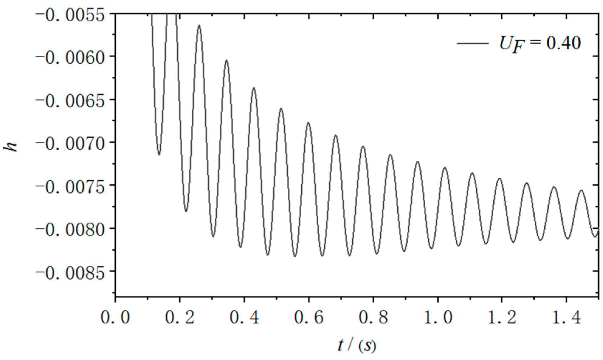
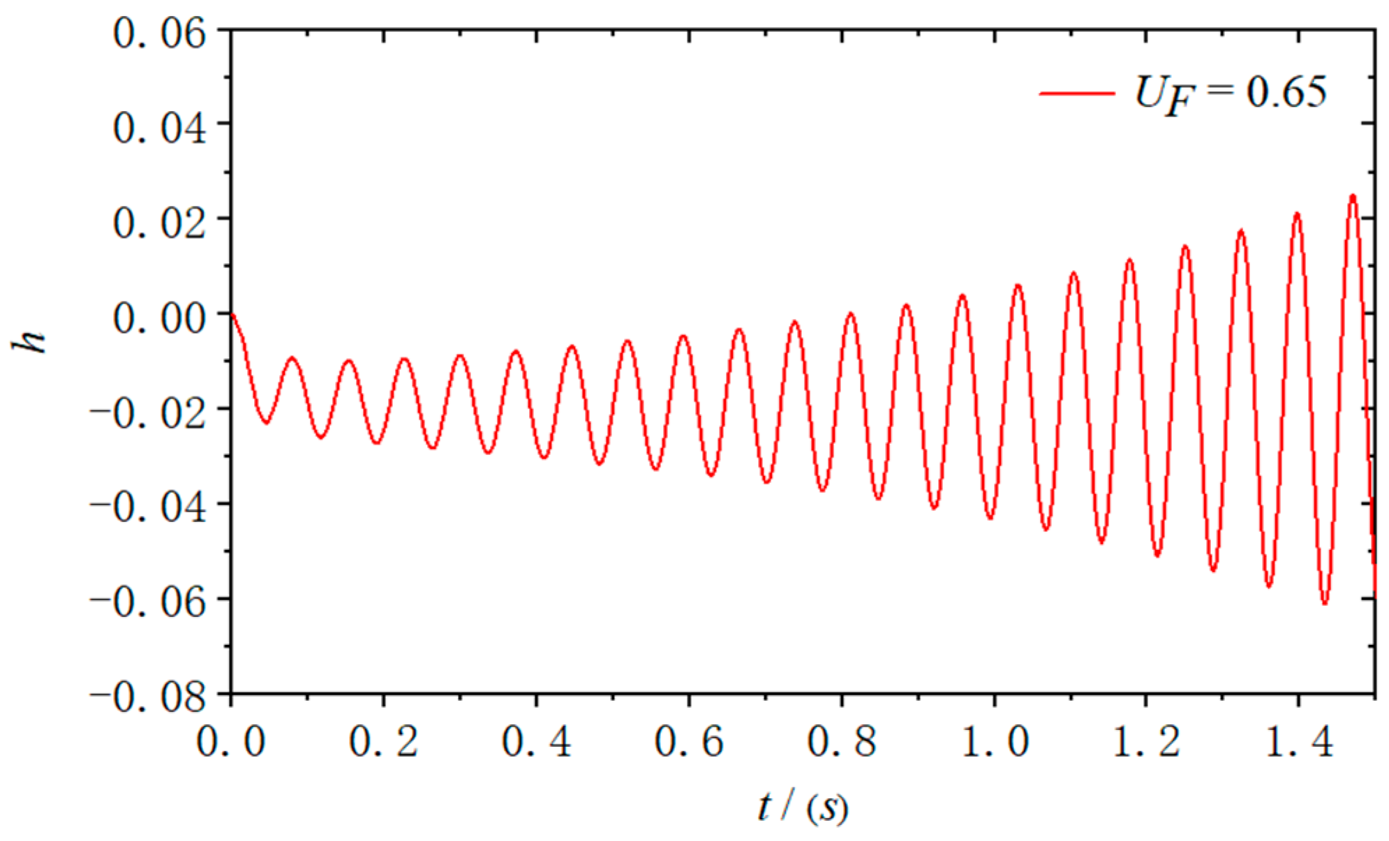
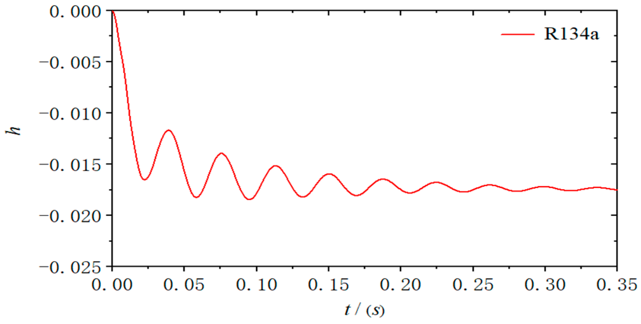
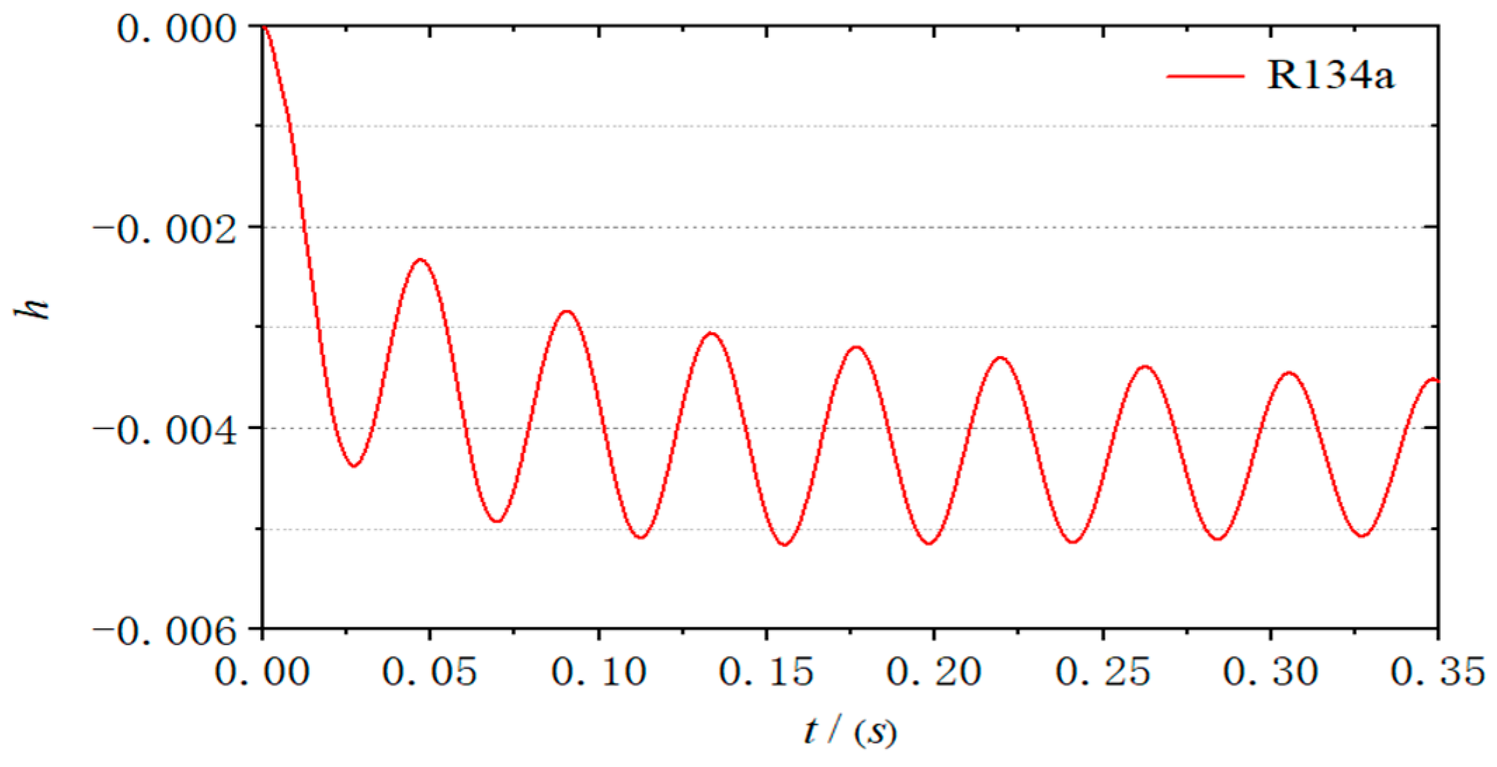
The initial angle of attack is set at 1 degree, with the incoming static pressure maintained at 1 atm. The time step is defined as 0.001 s. The responses of the structure under different dimensionless flutter velocities are presented in
Figure 1 and
Figure 2. Due to an initial angle of attack on the airfoil, it is assumed in the previous discussion that downward structural displacement is considered positive, resulting in an overall downward movement of the structure. Under the condition of
Ma = 0.85, it was observed that vibration converged at
UF = 0.40 and diverged at
UF = 0.65. Multiple adjustments in calculations determined that the dimensionless flutter velocity boundary for the airfoil at
Ma = 0.85 is
UF = 0.535.
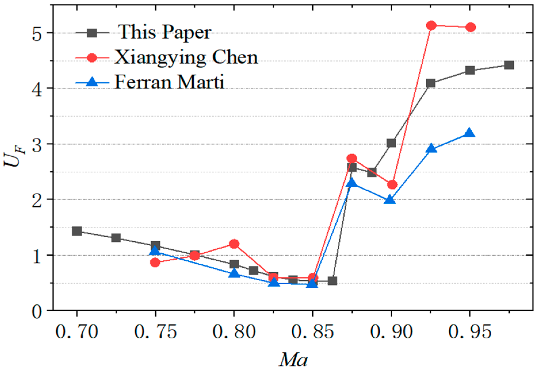
The dimensionless velocity boundary curves for the Mach number range of 0.6 to 0.95 were obtained using the same computational method, and a comparison with the literature results is presented in
Figure 3. The computational results presented in this study align well with the findings reported in the literature by Xiangying Chen [
19] and Ferran Marti [
20]. The curve
UF~
Ma exhibits an S-shaped profile, with a noticeable dip near a Mach number of 0.85. The analysis presented in this paper suggests that the computational method employed is suitable for investigating the flutter issues associated with two-dimensional wings.
4. The Peng–Robinson Equation
Heavy gases typically denote polymeric gases whose molecular weight is approximately thrice that of air [
21]. Commonly employed heavy gas media encompass R12 (Freon, CCl2F2), R134a (tetrafluoromethane, CH2FCF3), and so on. The present study primarily utilizes R134a as the working medium to conduct calculations on heavy gas oscillations, and its thermodynamic parameters are retrieved from the REFPROP9.1 software developed by the National Institute of Standards and Technology (NIST). R134a is free of chlorine atoms, which means it does not contribute to the depletion of the ozone layer. Additionally, it exhibits excellent safety performance. As a typical non-ideal gas, R134a fails to comply with the ideal gas equation of state. Instead, the Peng–Robinson equation typically delineates its thermodynamic properties [
22], as in Equation (11):
where
P, R, and
T denote the gas pressure, the gas constant, and the gas temperature;
denote a specific volume; and the other parameters are elaborated in Equation (12).
Among these parameters, P
c and T
c represent the gas’s critical pressure and critical temperature. At the same time, T
r =
T/T
c signifies the relative temperature, and
ω0 refers to the gas molecule’s acentric factor.
Table 2 exhibits a detailed comparative assessment of several thermodynamic parameters between the heavy gas medium and air (
T = 273.15 K;
P = 1 atm).
5. Flutter of Airfoil in Heavy Gas
5.1. Dynamic Similarity of Flutter
The Mach number, reduced frequency, and mass ratio are all critical similarity parameters in the wind tunnel testing of aircraft flutter:
U is the flow velocity;
a denotes the local sound speed;
ρ signifies the fluid density traversing through the structure;
m refers to the mass per unit extension.
b indicates the half-chord length of the wing, and
ω represents the natural frequency of the aircraft structure. The Mach number reflects the compressibility of a gas; the reduced frequency is defined as the ratio of the structural vibration velocity to the fluid flow velocity passing through it. The Theodorsen function relates reduced frequency to harmonic oscillation aerodynamic forces, demonstrating how reduced frequency characterizes the similarity of unsteady aerodynamic forces [
23].
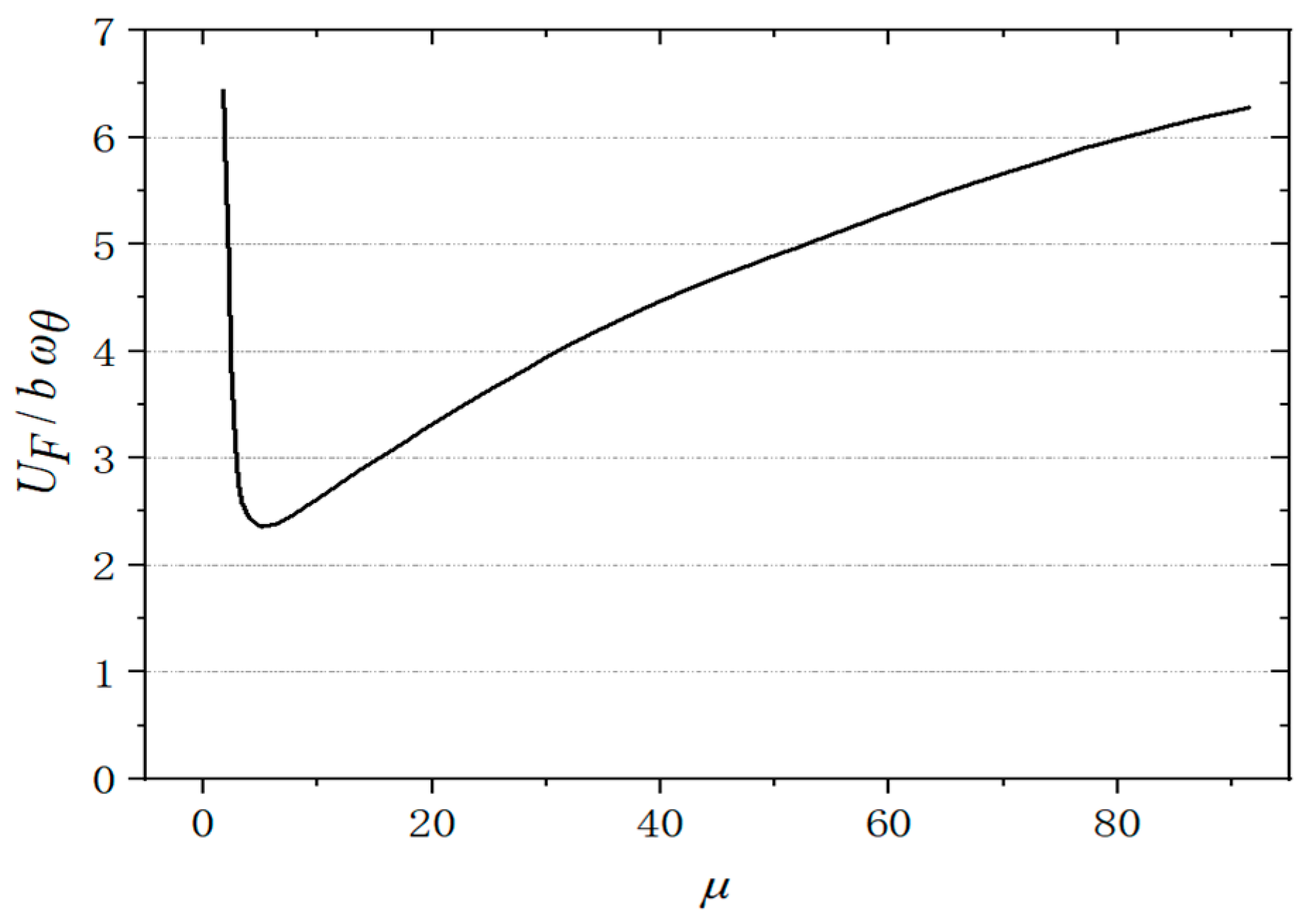
The mass ratio refers to the structural mass ratio to the surrounding fluid’s mass; variations in the mass ratio significantly influence dynamic responses. Altering the mass ratio can affect both the magnitude of oscillation amplitudes and, on the other hand, modify the interaction modes of vibrations. In systems characterized by structural and aerodynamic damping, improper mass scaling may obscure genuinely unstable modal combinations that exist, potentially exciting a different, inherently stable combination. As illustrated in
Figure 4, the relevant literature discusses the impact of the mass ratio parameter on the boundary of flutter velocity [
24]. The flutter velocity exhibits an almost linear increase with the rise in mass ratio, indicating that the flutter boundary of aircraft is highly sensitive to variations in this parameter. The mass ratio of different aircraft configurations varies and is also influenced by atmospheric density and flight altitude [
24]. The impact of the mass ratio on the flutter boundary of aircraft and its characteristics with changes in atmospheric density underscores the necessity for precise simulation of the mass ratio during wind tunnel testing.
It is essential to perform accurate dynamic similarity scaling of the model to conduct flutter tests. Inaccurate dynamic scaling may lead to imprecise predictions of flutter characteristics. An experiment on the F-16 rope-supported flutter model was conducted at TDT in 2010. The model exhibited a combination of secondary bending and torsional flutter modes during the testing process using air as the medium. However, this instability was not observed during subsequent tests with R134a as the medium, nor did it occur in actual flight tests. Given that both R134a and air mediums employed identical models and testing procedures, the test team concluded that the flutter instability observed in the air directly resulted from improper dynamic scaling of the mode [
25].
5.2. Structural Parameters
The present study utilizes R134a as the working medium for heavy gas calculations. R134a’s density is approximately 3.5 to 3.7 times that of air, while its sound speed is about half that of air. The relationship between the mass and frequency scale of the wind tunnel test model is as follows:
The parameters λ
m, λ
ρ, λ
L, λ
ω, and λ
a represent the mass scale factor, density scale factor, geometric dimension scale factor, frequency scale factor, and sound velocity scale factor, respectively. Employing a heavier gas with a greater density increases the model’s mass according to the mass ratio scale.
Figure 5,
Figure 6 and
Figure 7 illustrate the response curves corresponding to different mass ratios under identical inflow conditions (
Ma = 0.8125,
P = 1 atm,
T = 320 K) and consistent model stiffness (
ωh =
ωα =100 rad/s).
The 2D wing model with a mass ratio of 60 exhibits critical flutter under the given airflow conditions. In the R134a gas medium, although the model’s structural mass remains identical, the response curves converge rapidly. Increasing the airfoil’s mass significantly amplifies its vibration amplitude; however, it still fails to reach a harmonic state. The dissimilarity in reduced frequency may be a primary reason for not satisfying structural dynamic similarity.
The frequency scaling indicates that when using a heavier gas with lower sound speed as the flow medium, it is necessary to appropriately reduce the structural stiffness to meet the requirements for reduced frequency similarity. This approach allows for reasonably determining the flutter boundary for airfoil configurations in a heavy gas environment.
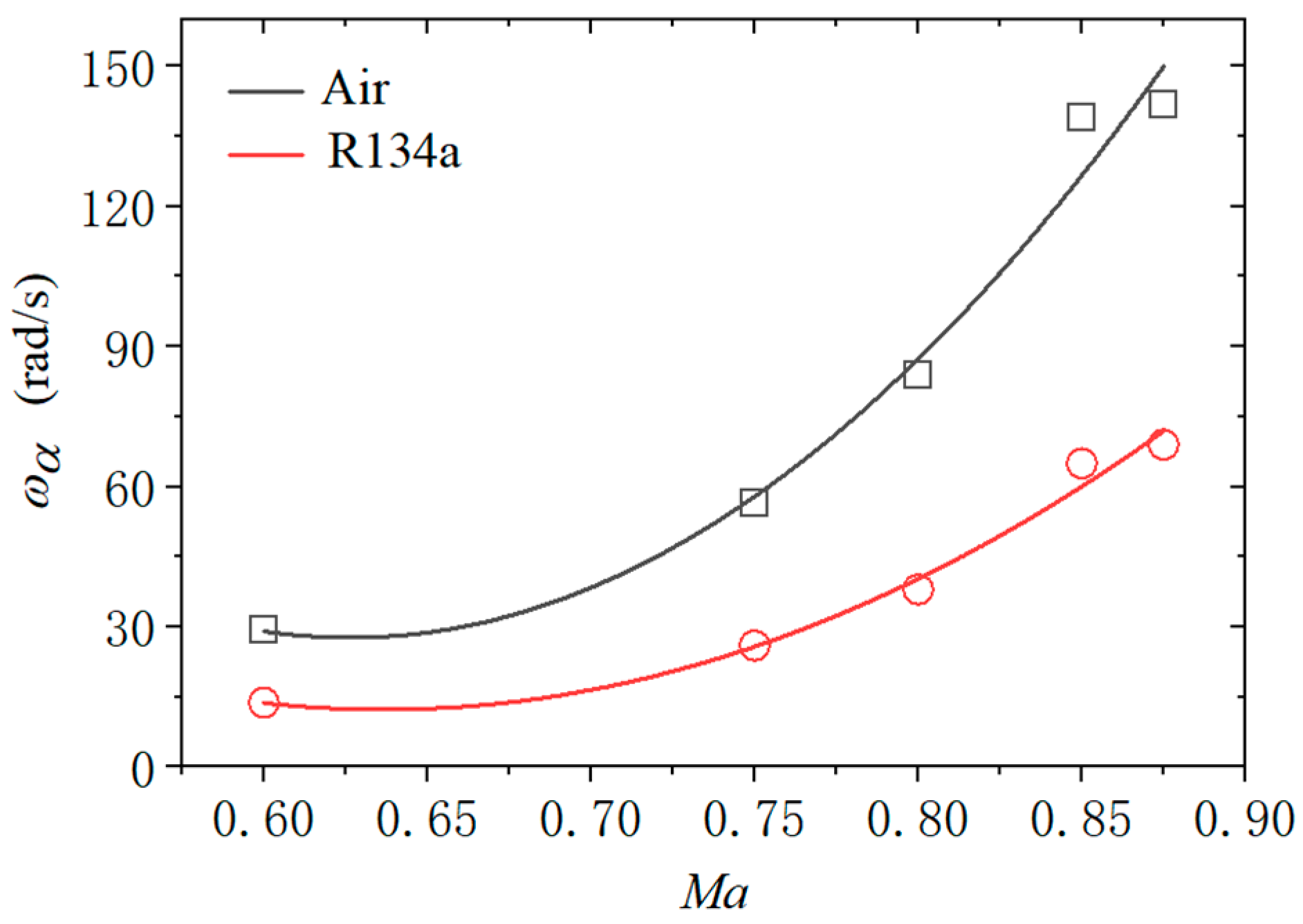
Figure 8 illustrates the required structural natural frequency values for the 2D wing to reach a critical flutter state under identical inflow conditions (
P = 1 atm,
T = 300 K) and mass ratio (
μ = 60). Compared to air, the structural natural frequency required in the R134a medium is significantly lower, approximately 46% to 48% of those needed in air.
5.3. Similar Parameters of Flow
The similarity of flow-related parameters is equally important for the issue of flutter. Meeting the conditions of flow similarity allows for a more accurate and realistic representation of analogous flow phenomena. The primary aspect of flow parameter similarity is the Mach number similarity. The expressions for the flow dynamic pressure
qF and the dimensionless dynamic pressure
qD are as follows:
where
ρ∞ is the density of incoming flow in Equations (15) and (16), and the Mach number is a crucial parameter for characterizing flow characteristics. In this section, we compare the flutter pressure of an airfoil in two different media, air and R134a gas, under identical incoming Mach numbers. The mass ratio is 60, with
ωα = ωh = 100 rad/s in air. For R134a, the model’s natural frequency is dynamically scaled based on reduced frequency similarity.
Figure 9 illustrates the comparison between the two cases; it shows that, compared to air, the flutter dynamic pressure boundary in the R134a medium has been reduced by approximately 20%; the two entities generally exhibit a consistent trend of increase and decrease.
In addition to the similarity in Mach numbers, related studies have also indicated that different families of airfoil shapes and varying specific heat ratios of the flow medium must satisfy certain similarity relationships when operating in the transonic regime. Von Karman [
26], Guderley and Yoshihara [
27], and Cole [
28] derived the equation for the velocity potential function
φ of small disturbances in transonic flow based on the small disturbance equations through a coordinate transformation approach:
The parameter
δc represents the airfoil thickness ratio, while
K1 denotes the similarity parameter for transonic flow. The similarity parameters for transonic flow are derived when the Mach number is approximately equal to 1. Spreiter and colleagues [
29,
30] conducted extensive fitting and analysis of a substantial amount of transonic experimental data, providing similarity parameter
χ that is applicable over a broader range of Mach numbers:
The following form of the subsonic small disturbance velocity potential function is
Assuming that
Ac represents the aspect ratio of the wing and
αc denotes the angle of attack of the wing, we define
The similarity criteria for aerodynamic coefficients in transonic flow are as follows:
The variables , , , and represent the similarity functions for the pressure coefficient, lift coefficient, pitching moment coefficient, and drag coefficient, respectively. The transonic flow similarity parameter χ is commonly employed to elucidate the flow similarity of airfoil families with differing thickness ratios in an air medium. If two airfoils exhibit the same similarity parameter χ in their surrounding flow, then these two flows can be considered similar. In the context of heavy gas flutter issues, this parameter can also describe the transonic flow similarity of models with identical thickness ratios in gaseous media characterized by different specific heat ratio parameters.
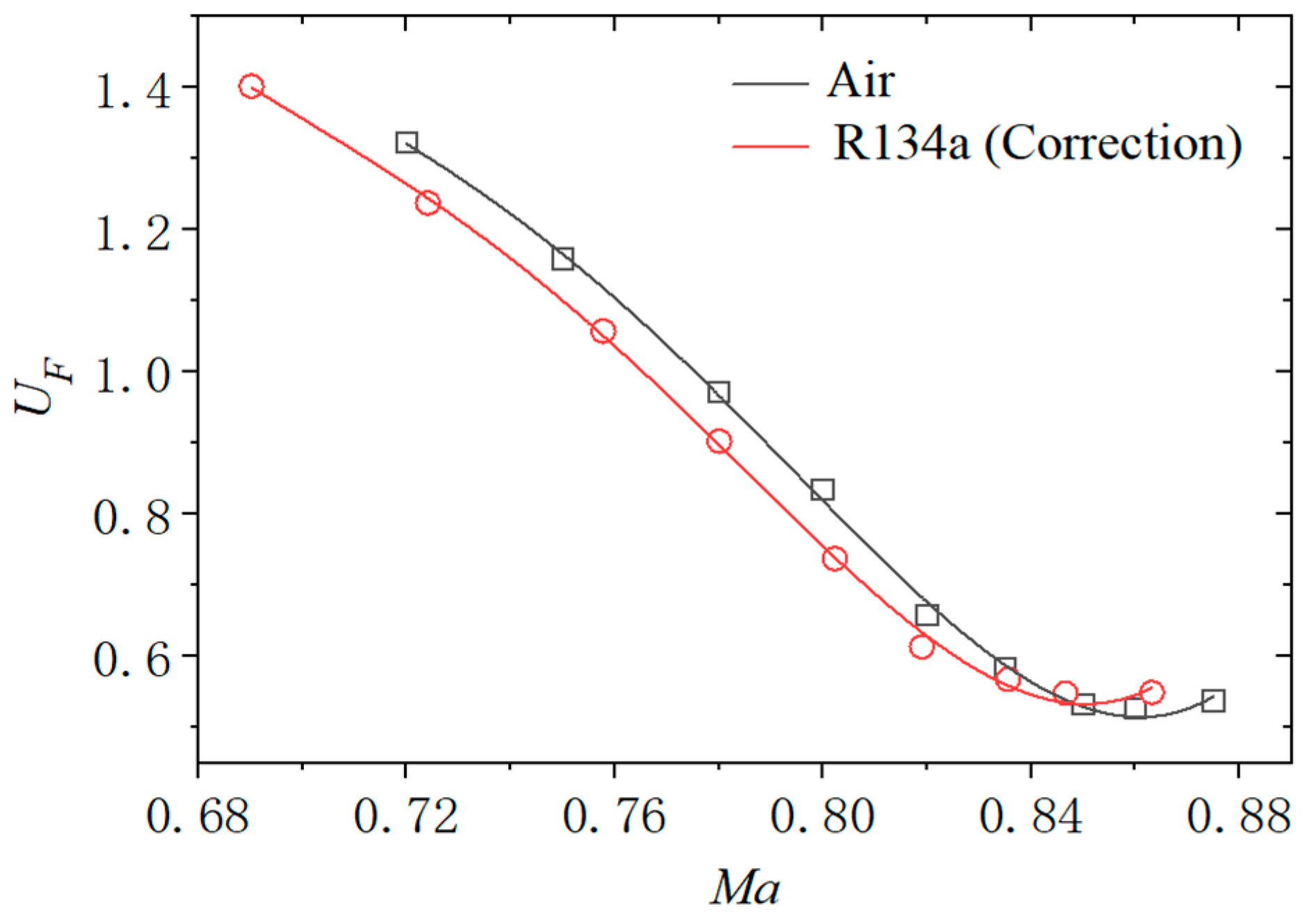
The specific heat ratio of heavy gases is lower than that of air. Therefore, a higher Mach number should be matched accordingly. The numerical results in
Figure 10 indicate that the incoming Mach number of the R134a medium is corrected based on the transonic flow similarity parameter
χ. Furthermore, a structural model stiffness redesign is conducted using reduced frequency similarity. The resulting dimensionless flutter pressure curves for air and R134a medium environments are illustrated in
Figure 10. The results indicate that, after adjusting the Mach number based on the similarity parameters of transonic flow, the dimensionless flutter speed pressure for a 2D wing in the heavy gas R134a medium is slightly lower than that in air, with a value of approximately 90% of that observed in air. Across the analyzed Mach number range, both media show a consistent trend in the variation in dimensionless flutter speed pressure for a 2D wing.
5.4. Differences in Flutter Caused by Specific Heats
The heavy gas medium is a typical non-ideal gas, which differs from air in that its specific heat ratio varies significantly with environmental factors, particularly temperature.
Table 3 presents the values of the specific heat ratios for air and the heavy gas R134a at standard atmospheric pressure across different temperatures. The primary objective of introducing heavy gas media is to address the issue of excessive weight in wind tunnel test models, ensuring that the mass ratio closely resembles actual aircraft and real flight environments. Considering the significant differences in flutter characteristics caused by dissimilar specific heat ratios is essential.
The similarity parameters for transonic flow are derived when the Mach number is approximately equal to 1. Spreiter and colleagues [
29,
30] conducted extensive fitting and analysis of a substantial amount of transonic experimental data, providing a similarity parameter χ applicable to a broader range of Mach numbers.
In the previous study on 2D airfoil flutter calculations, temperature was treated as a variable. The inflow conditions, especially the inflow temperature, significantly affect the specific heat ratio of the R134a medium. To discuss the impact of specific heat ratios of heavy gas media on flutter characteristics, we fixed the air and R134a mediums at a flow temperature and pressure (
P = 1 atm,
T = 300 K) to keep the specific heat ratio constant. This study conducts a comparative analysis of the flutter characteristics of 2D airfoils at different mass ratios (
μ = 30, 60, 100). The flutter boundary is obtained by adjusting the mass and stiffness of the structural model.
Table 4 presents the dimensionless critical flutter speeds under various mass ratios. The subscripts “Air” and “R134a” refer to conditions for air and R134a, respectively (
γAir = 1.4017,
γR134a = 1.1187).
Under the same Mach number conditions, the dimensionless flutter velocity of a 2D wing model in an R134a medium environment is slightly higher than that in air. The Mach number of R134a is corrected based on the transonic flow similarity parameter
χ, resulting in the dimensionless flutter velocity boundary curve illustrated in
Figure 11. The dimensionless flutter velocity in a heavy gas environment is slightly lower than that in air. The numerical results are consistent with the magnitude and trend in
Figure 11.
5.5. Flutter Similarity Law in Heavy Gas
Conducting practical experiments in a heavy gas wind tunnel can result in discrepancies in test data due to differences in the gaseous media’s specific heat ratios. Therefore, it is essential to establish a comprehensive and robust correction method.
In 1998, Bendiksen developed the similarity law for unsteady transonic flow using a 2D wing flutter model under quasi-steady conditions [
31,
32]. The similarity law governing unsteady transonic flow is defined by the similarity parameter
ψ associated with transonic flutter, as presented in Equation (26).
The similarity law for transonic conditions is frequently employed in analyzing transonic flutter similarities across varying thickness ratios within homologous airfoils. Similarity can be achieved by utilizing airfoils with identical thickness ratios to investigate heavy gas flutter phenomena. The integration of transonic flow similarity laws with transonic flutter similarity principles is shown as Equations (27) and (28):
In the above equations, the subscript “
a” represents the corresponding parameter in the air medium, whereas the subscript “
h” denotes the corresponding parameter in the heavy gas medium. The simultaneous satisfaction of Equations (27) and (28) in media with different specific heat ratios indicates that their flutter characteristics are similar. Therefore, the modified relationship can convert flutter boundaries across various media.
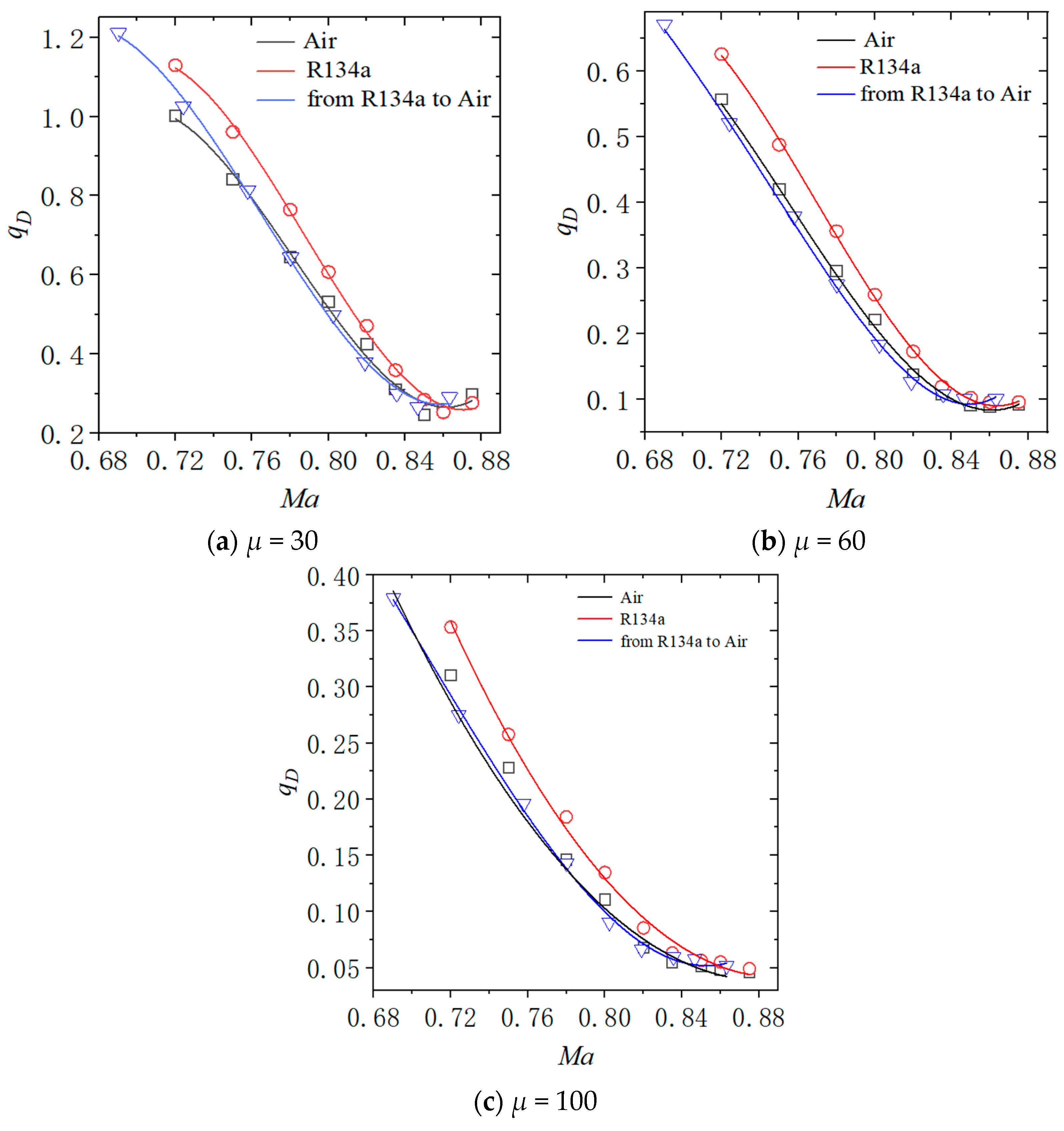
Figure 12 shows the results of correcting computational data for 30, 60, and 100 mass ratios using the heavy gas flutter correction method based on Equations (27) and (28).
The correction method for heavy gas flutter established by Equations (27) and (28), as illustrated in
Figure 12, demonstrates a good explanation of the similarity in dimensionless flutter dynamic pressures between wing models using R134a and air. The corrected results of the flutter data in R134a align well with those obtained from air data. This method is applicable for correcting flutter data of 2D rigid models involving heavy gases. However, it is noteworthy that when considering smaller mass values, such as
μ = 30, and a larger reduced frequency, specifically for Mach numbers greater than 0.85, applying heavy gas flutter similarity laws does not provide satisfactory explanations for the related issues; possible reasons for this situation include the following:
The similarity parameter ψ, based on the quasi-steady (k → 0+) assumption, requires further validation regarding its accuracy at a larger reduced frequency.
The reduced frequency at the critical flutter state is negatively correlated with the product of mass ratio and dimensionless flutter velocity. A smaller mass ratio corresponds to a larger reduced frequency, which limits the applicability of correction methods for flutter similarity laws in heavy gases.
Factors such as mass ratio and the magnitude of reduced frequency should be considered critical elements requiring correction. Consequently, a comprehensive and effective method for correcting heavy gas environment flutter data remains to be further developed and researched.
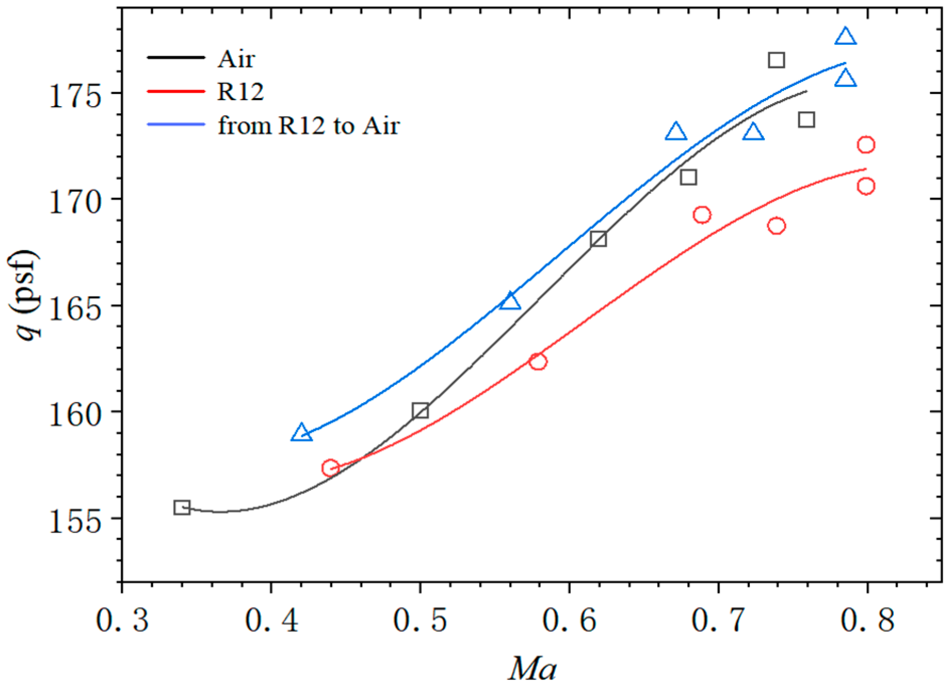
5.6. The TDT Wind Tunnel Flutter Results
The introduction section of this article provides a brief overview of the experimental data from the TDT wind tunnel. For a more detailed and specific analysis, readers should refer to ZHA’s paper [
33]. In order to compare with the numerical results presented in this study, this section presents the flutter boundary for the TDT two-degree-of-freedom model BSCW, as shown in
Figure 13. Additionally, modifications based on the similarity laws established in this paper are applied to the figure.
The similarity law for heavy gases also demonstrates a favorable correction effect for BSCW. However, it is noteworthy that BSCW employs a model with identical mass and stiffness in both media, which results in the failure to satisfy structural dynamic similarity. The numerical results presented in this paper are analogous to those of BSCW; specifically, the flutter boundaries in a heavy gas environment are slightly lower than those observed in conventional air flutter. After applying the similarity law corrections, certain improvements have been achieved. In contrast to BSCW, this study has made adjustments to the computational model’s structure to meet dynamic similarity criteria, representing an advancement and further discussion of previous research.
6. Conclusions and Discussion
The present study utilizes a time-domain analysis method for fluid–structure interaction to explore the flutter characteristics of the two-dimensional airfoil NACA64A010 in heavy gas media and potential correction methods. It highlights the significant influence of structural dynamic similarity parameters, especially the mass ratio, on wind tunnel flutter tests. Building on this foundation, we investigate how structural parameters affect the flutter boundary in heavy gases. The conclusions of this research are as follows:
Models with identical mass reach critical states in the air but exhibit convergent responses in R134a. Under consistent inflow temperature and pressure, structures achieve harmonic vibration in R134a, reducing their natural frequency to 46~48% of that observed in air. With the same incoming flow Mach number, designing the R134a medium model based on reduced frequency similarity results in a flutter pressure decrease of approximately 20% compared to air. By adjusting the incoming flow Mach number for heavy gas R134a according to derived similarity laws for transonic flow, it is found that the dimensionless flutter dynamic pressure of wings in R134a is about 10% lower than that in air. Numerical calculations are used to discuss the differences in heavy gas flutter due to variations in the specific heat ratio. Additionally, a similarity law for heavy gas flutter is established based on the transonic flow similarity parameter χ and the transonic flutter similarity parameter ψ. The numerical results for mass ratios of 30, 60, and 100 have been corrected. The flutter similarity law in heavy gases accounts for the differences in flutter behavior between binary rigid wings in heavy gas and air due to varying specific heat ratios. This law aids in the dimensional analysis and conversion of flutter dynamic pressure between the two media. However, at lower mass ratios like μ = 30 and higher reduced frequencies corresponding to Mach numbers above 0.85, the applicability of heavy gas flutter similarity laws diminishes.
The present study conducts a preliminary investigation into the issue of flutter in heavy gas environments, providing valuable references for the design of models under such conditions. By addressing the differences in aerodynamic flutter pressures between air and heavy gases and proposing corresponding correction methods, this research aims to support practical engineering applications.
The work presented in this paper still exhibits several limitations that need to be addressed as future research objectives. This study employs the Euler equations as the governing equations for flow control, neglecting the effects of viscosity-related phenomena such as flow separation and turbulence on the flutter problem. Furthermore, calculations are based on a 2D model; conducting research using a 3D aircraft model would provide results closer to reality. The flutter correction method for heavy gases proposed in this paper is only accurate within a limited range of conditions. To develop a more comprehensive and precise correction method, further extensive research is required. Conducting wind tunnel tests with heavy gases and integrating test data will effectively advance the development of similarity law correction methods for heavy gas flutter.
Author Contributions
Writing—original draft preparation, Z.H.; resources, S.H.; funding acquisition, B.L.; writing—review and editing, methodology, J.Z. All authors have read and agreed to the published version of the manuscript.
Funding
This work was supported by the National Science Foundation of Sichuan Province (2023NSFSC1295).
Data Availability Statement
The data presented in this study are available on request from the corresponding author.
Conflicts of Interest
The authors declare no conflicts of interest.
References
- Yu, Q.Y.; Yin, Y.P. Discussion on flutter of aircraft and bridge. Mech. Eng. 2023, 45, 721–727. [Google Scholar]
- Yang, X.; Liu, N.; Guo, C.; Zhang, Y.; Sun, J.; Zhang, G.; Yu, X.; Yu, J.; Hou, L. A survey of aeroelastic wind tunnel test techonlogy of flight vehicles. Acta Aerodyn. Sin. 2018, 36, 995–1008. [Google Scholar]
- Yan, Y.; Lu, B.; Yang, X.; Guo, H.; Yu, L. Review on buzz wind tunnel test technology for aircraft control surfaces. Acta Aerodyn. Sin. 2022, 40, 1–9. [Google Scholar]
- Corrado, G.; Ntourmas, G.; Sferza, M.; Traiforos, N.; Arteiro, A.; Brown, L.; Chronopoulos, D.; Daoud, F.; Glock, F.; Ninic, J.; et al. Recent progress, challenges and outlook for multidisciplinary structural optimization of aircraft and aerial vehicles. Prog. Aerosp. Sci. 2022, 135, 100861. [Google Scholar] [CrossRef]
- Zhang, W.; Zhao, K.; Xia, L.; Gao, Z. A multi-disciplinary global/local optimization method for flying-wing airfoils design. Acta Aerodyn. Sin. 2021, 39, 37–52. [Google Scholar]
- Perry, B.; Thomas, E.N. Activities in Aeroelasticity at NASA Langley Research Center. NASA Langley Res. Cent. 1997, 53, 77–88. [Google Scholar]
- Bryan, E.; Dansberry, M.H.; Robert, M. Experimental unsteady pressures at flutter on the Supercritical Wing Benchmark Model. In Proceedings of the 34th Structures, Structural Dynamics and Materials Conference, La Jolla, CA, USA, 19–22 April 1993; p. 1592. [Google Scholar]
- Foughner, J.T., Jr.; Land, N.S.; Yates, E.C., Jr. Measured and Calculated Subsonic and Transonic Flutter Characteristics of a 45 Deg Sweptback Wing Planform in Air and in Freon-12 in the Langley Transonic Dynamics Tunnel; NASA-TN-D-1616; NASA: Washington, DC, USA, 1963. [Google Scholar]
- Zha, J.; Zeng, K.C.; Kou, X.P.; Yang, X.; Zhang, H. Transonic flow characteristics of supercritical airfoil in heavy gas medium. J. Aerosp. Power. 2021, 36, 1894–1905. [Google Scholar]
- Liu, Y.P.; Kou, X.P.; Zha, J.; Yu, L.; Lu, B. The isentropic flow characteristics of heavy gas medium. J. Aerosp. Power 2023, 1–9. [Google Scholar] [CrossRef]
- Liu, Y.P.; Zha, J.; Hu, Z.; Kou, X.P.; Yu, L.; Lu, B. Correction of Aerodynamic Characteristics in Heavy Gas Medium. J. Aerosp. Power 2024, accepted. [Google Scholar]
- Liu, Y.P.; Zha, J.; Hu, Z.; Kou, X.P.; Yu, L.; Lu, B. A survey of the test data correction method in heavy gas wind tunnel. J. Aerosp. Power 2024, accepted. [Google Scholar]
- Versteeg, H.K.; Malalasekera, W. An Introduction to Computational Fluid Dynamics: The Finite Volume Method, 2nd ed.; Pearson Education Limited: Harlow, UK, 2007. [Google Scholar]
- Christopher, J.G.; Henry, G.W.; Luca, G.; Jason, M.R. Implementation of semi-discrete, non-staggered central schemes in a colocated, polyhedral, finite volume framework, for high-velocity viscous flows. Int. J. Numer. Methods Fluids 2010, 63, 1–21. [Google Scholar]
- Rodden, W.P. Theoretical and Computational Aeroelasticity; Crest Publishing: Santa Rosa, CA, USA, 2011. [Google Scholar]
- Juan, J.A.; Antony, J. Filly-Implicit Time-Marching Aeroelast ic Solutions. In Proceedings of the 32nd Aerospace Sciences Meeting and Exhibit, Reno, NV, USA, 10–13 January 1994. [Google Scholar]
- Liu, F.; Cai, J.; Zhu, Y. Calculation of Wing Flutter by a Coupled Fluid-Structure Method. J. Aircrt. 2001, 38, 334–342. [Google Scholar] [CrossRef]
- Isogai, K. Transonic dip mechanism of flutter of a sweptback wing. AIAA J. 1981, 19, 1240–1242. [Google Scholar] [CrossRef]
- Chen, X.; Zha, G.C.; Hu, Z.J.; Yang, M.T. Flutter prediction based on fully coupled fluid-structural interactions. In Proceedings of the 9th National Turbine Engine High Cycle Fatigue Conference, Pinehurst, NC, USA, 16–19 March 2004. [Google Scholar]
- Marti, F.; Liu, F. Flutter Study of NACA 64A010 A-irfoil Using URANS and e^N Transition Models C-oupled with an Integral Boundary Layer Code. In Proceedings of the 55th AIAA Aerospace Sciences Meeting, Grapevine, TX, USA, 9–13 January 2017. [Google Scholar]
- Cole, S.R.; Garcia, J.L. Past, present and future capabilities of the Langley Transonic Dynamics Tunnel from an aeroelasticity perspective. In Proceedings of the 41st Structures, Structural Dynamics, and Materials Conference and Exhibit, Atlanta, GA, USA, 3–6 April 2000. [Google Scholar]
- Poling, B.E.; Prausnitz, J.M.; O’connell, J.P. The Properties of Gases and Liquids; The McGRAW-Hill Companies: New York, NY, USA, 2001; Volume 5. [Google Scholar]
- Theodorsen, T. General Theory of Aerodynamic Instability and the Mechanism of Flutter; NASA: Washington, DC, USA, 1979; NACA-TR-496. [Google Scholar]
- Hodges, D.H.; Pierce, G.A. Introduction to Structural Dynamics and Aeroelasticity; Cambridge University Press: Cambridge, UK, 2011; Volume 11. [Google Scholar]
- Ivanco, T.G. Unique Testing Capabilities of the NASA Langley Transonic Dynamics Tunnel, an Exercise in Aeroelastic Scaling. In Proceedings of the AIAA Ground Testing Conference, San Diego, CA, USA, 24–27 June 2013. [Google Scholar]
- Von, K. The Similarity Law of Transonic Flow. J. Math. Phys. 1947, 28, 182–190. [Google Scholar]
- Guderley, G.; Yoshihara, H. The Flow over a Wedge Profile at Mach Number 1. J. Aeronaut. Sci. 1950, 17, 723–735. [Google Scholar] [CrossRef]
- Cole, J.D. Drag of a Finite Wedge at High Subsonic velocity. J. Math. Phys. 1951, 30, 79–93. [Google Scholar] [CrossRef]
- Spreiter, J.R. On the Application of Transonic Similarity Rules to Wings of Finite Span; NACA-TR-1153; NASA: Washington, DC, USA, 1953. [Google Scholar]
- Spreiter, J.R. On alternate forms for the basic equations of transonic flow theory. J. Aeronaut. Sci. 1954, 21, 70–72. [Google Scholar] [CrossRef]
- Bendiksen, O.O. Transonic Similarity Rules for Flutter and Divergence. In Proceedings of the 39th AIAA/ASME/ASCE/AHS/ASC Structures, Structural Dynamics, and Materials Conference and Exhibit, Long Beach, CA, USA, 20–23 April 1998. [Google Scholar]
- Bendiksen, O.O. Improved similarity rules for transonic flutter. In Proceedings of the 40th Structures, Structural Dynamics, and Materials Conference and Exhibit, St. Louis, MO, USA, 12–15 April 1999. [Google Scholar]
- Hu, Z.; Lu, B.; Liu, Y.; Yu, L.; Kou, X.; Zha, J. Three-Dimensional Flutter Numerical Simulation of Wings in Heavy Gas and Transonic Flutter Similarity Law Correction Method. Aerospace 2024, 11, 932. [Google Scholar] [CrossRef]
| Disclaimer/Publisher’s Note: The statements, opinions and data contained in all publications are solely those of the individual author(s) and contributor(s) and not of MDPI and/or the editor(s). MDPI and/or the editor(s) disclaim responsibility for any injury to people or property resulting from any ideas, methods, instructions or products referred to in the content. |
© 2025 by the authors. Licensee MDPI, Basel, Switzerland. This article is an open access article distributed under the terms and conditions of the Creative Commons Attribution (CC BY) license (https://creativecommons.org/licenses/by/4.0/).


