Article

Effect of Dynamic Flexural Strength on Impact Response Analysis of AlN Substrates for Aerospace Applications

1
Institute of Electronics Packaging Technology and Reliability, Department of Mechanics, Beijing University of Technology, Beijing 100124, China
2
College of Physics and Optoelectronic Engineering, Shenzhen University, Shenzhen 518060, China
*
Author to whom correspondence should be addressed.
Aerospace 2025, 12(3), 221; https://doi.org/10.3390/aerospace12030221
Submission received: 21 January 2025 / Revised: 6 March 2025 / Accepted: 7 March 2025 / Published: 8 March 2025

Abstract

:
Electronic devices play an extremely important role in the aerospace field. Aluminum nitride (AlN) is a promising ceramic material for high-reliability electronic packaging structures that are subjected to impact loads during service. Quasi-static and dynamic flexural tests were conducted to determine the rate-dependent flexural strengths of AlN ceramics. The impact response of the AlN substrates was investigated using experimental tests and a smeared fixed-crack numerical model. The critical velocity of the impactor and the failure mode of the ceramic plate can be accurately predicted using the Drucker–Prager criterion with the scaled fracture-strength parameter. The radial cracks on the ceramic plate upon impact were well reproduced via the proposed novel numerical technique, showing better accuracy compared to the widely used Johnson–Holmquist II (JH-2) model. The effect of impactor nose shape and deflection angles were further investigated to better illustrate the low-velocity impact response of AlN ceramic substrates. Based on the dynamic flexural-strength testing results, this study achieves the prediction of low-speed impact response for AlN ceramic structures, thereby providing technical support for the impact reliability analysis of aerospace ceramic-packaging devices.

Graphical Abstract

1. Introduction

Aluminum nitride (AlN) is a promising electronic substrate and packaging material for aerospace, vehicular, and military device applications [1,2]. AlN substrates have already been utilized in high-power electronic devices, micro-electro mechanical systems (MEMS) and integrated passive devices due to the excellent physical and chemical properties [3,4,5]. Aerospace electronic devices are typically subjected to impact and high acceleration shock loading during service, such as spacecraft landing impact and projectile penetration [6,7]. As a typical brittle material, the tensile strength of AlN ceramics is one order of magnitude lower than its compressive strength [8]. Dynamic-bending-induced tensile fracture is the main failure mode of ceramic substrates under high-acceleration loading conditions, which is a threat to the reliability of electronic devices and safety of aerospace vehicles. However, present studies mainly focus on the dynamic compression tests on bulk ceramic materials [9,10,11] and the ballistic response analysis of ceramic protective structures in the field of military and defense technology [12,13,14]. The accurate evaluation of the dynamic flexural properties of AlN ceramics is necessary for an impact reliability analysis of packaging structures, but related studies are still limited at present.
Numerical modeling is an efficient technique for the mechanical analysis and failure prediction of engineering structures [15,16,17,18]. However, an accurate assessment of the dynamic response of ceramic structures remains challenging because of the tension-compression asymmetry, rate effect, and crack-induced discontinuous computing domain. A novel smeared fixed-crack finite-element method (FEM) model was recently established and applied to model the impact responses of glass structures [19,20]. In this model, each element can contain at most two orthogonal cracks in this model, and the onset of cracks is controlled by a stress-state-related failure criterion [21]. In addition, the loading-rate effect of brittle materials can be considered in this model to effectively capture the dynamic responses of the ceramic structures [22].
Dynamic compression tests have been conducted on engineering ceramics in the past few decades and a positive loading-rate effect has been reported by different researchers [9,23,24,25]. The compression strain-rate-dependent parameters have also been implemented in different numerical models and these models can provide good prediction results for high-velocity impact problems on ceramics [26,27,28,29]. However, a bending fracture is the main failure mechanism for brittle materials under low-velocity impact and high-acceleration shock loading conditions. The application of compression-rate-dependent strength data on bending-fracture-dominated low-velocity impact problems is unreasonable. Researchers have developed different experimental techniques, such as a drop-impact device and modified split Hopkinson pressure (SHPB) bar, to obtain the dynamic flexural strength of brittle materials [30,31,32]. The dynamic impact response of brittle specimens can be analyzed based on the obtained stress signals and synchronous high-speed images. Research on the effect of rate-dependent flexural strength on the failure prediction of ceramic structures under low-velocity impact is necessary and thus presented in this work.
In this study, quasi-static and dynamic flexural tests were performed to obtain rate-dependent flexural strength data for AlN ceramics used for aerospace devices. The low-velocity impact response of AlN substrates was investigated using experimental tests and a smeared fixed-crack numerical model. The effects of the rate-dependent flexural strength and different failure criteria on the failure prediction of the AlN substrates under low-velocity impacts were analyzed. This proposed numerical technique was also compared to the well-known constitutive model for a large amount of strain, high strain rate, and high-pressure applications of ceramics. The validated model was finally utilized to study the effect of impactor nose shape and deflection angles on low-velocity impact response of AlN ceramic tiles.

2. Experimental Tests

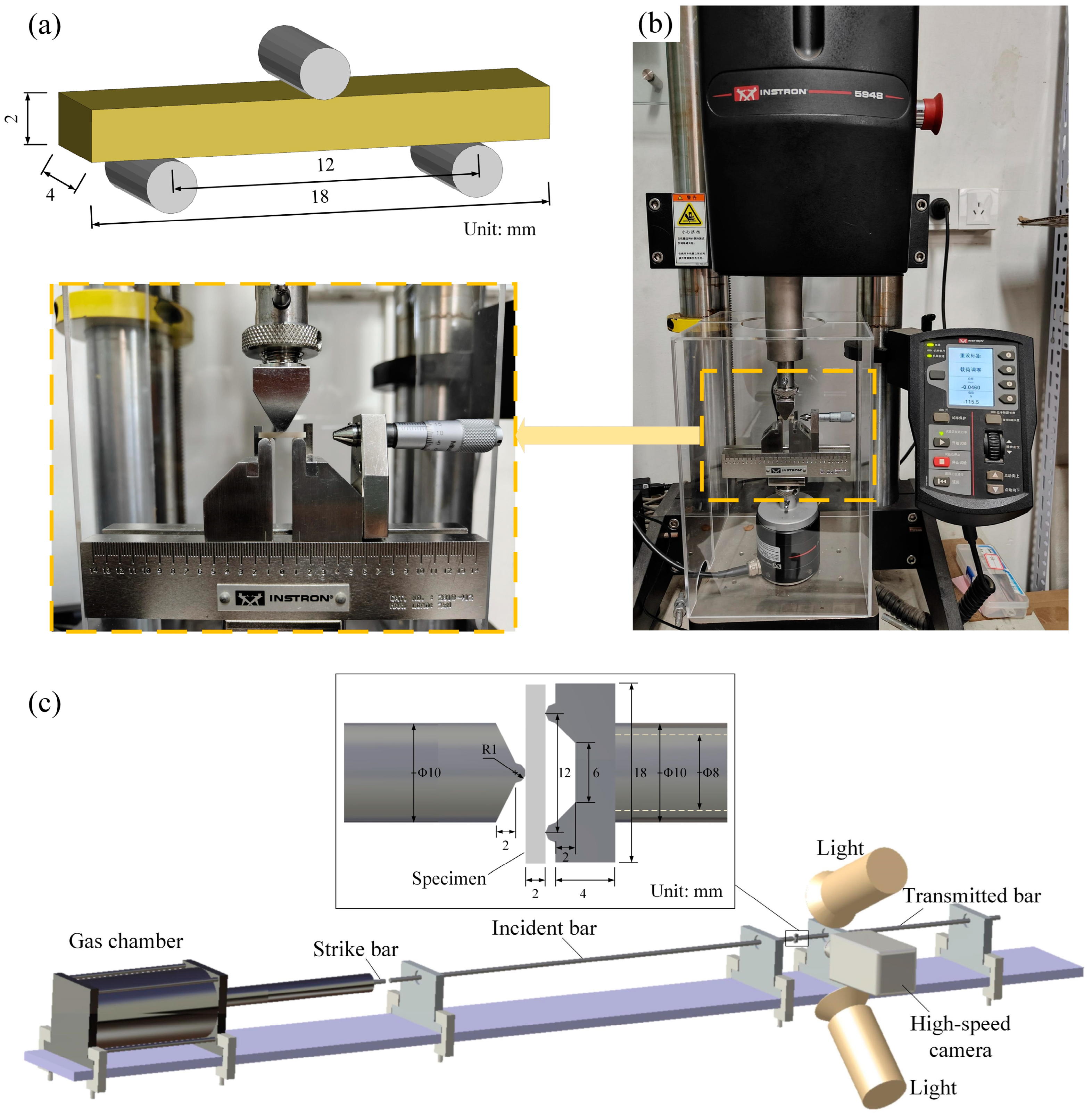
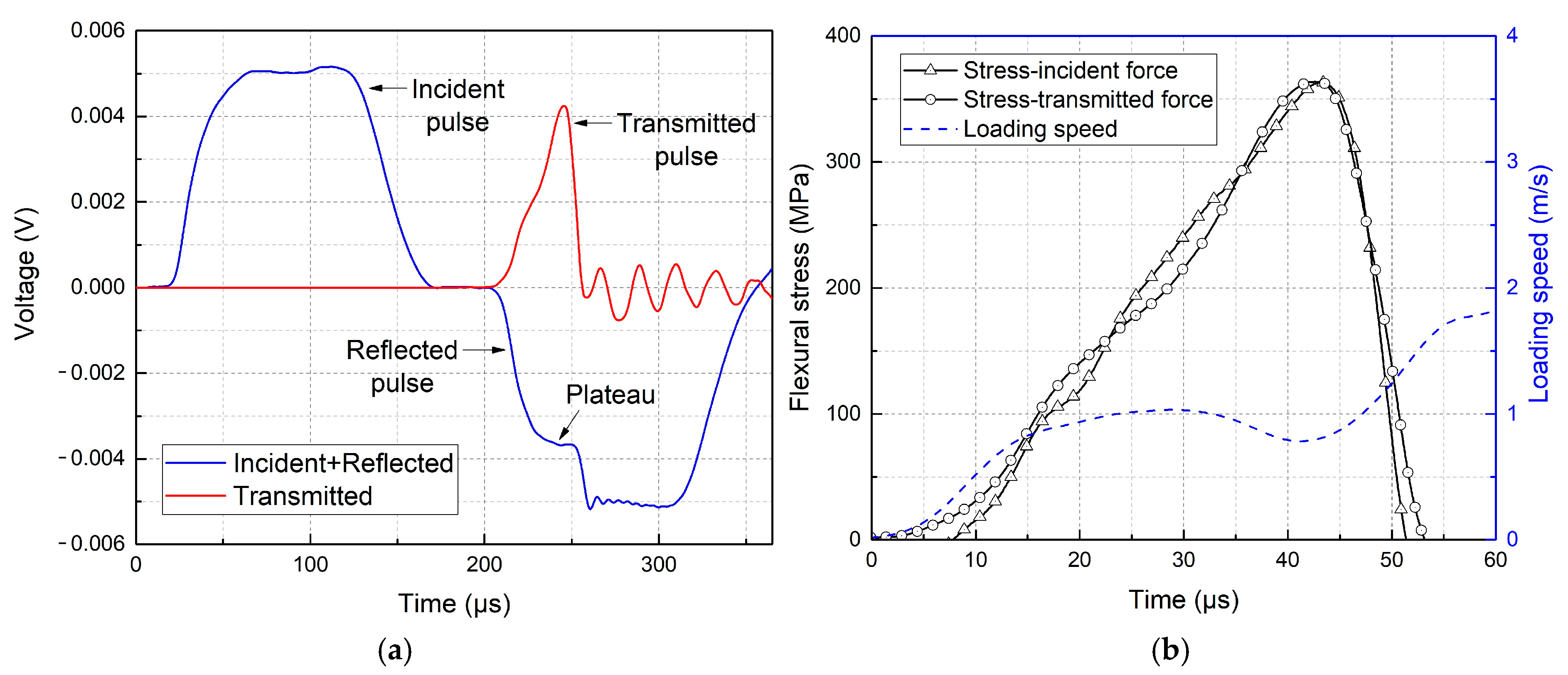
2.1. Quasi-Static and Dynamic Flexural Tests

AlN specimens with dimensions of 18 mm × 4 mm × 2 mm were used for three-point bending tests with an Instron-5948 micro-tester, as shown in Figure 1a,b. The flexural strength can be calculated by [33].
σ f = 3 F m a x L 2 b h 2
where σ f is the flexural strength, F m a x represents the failure load, and b, L, and h represent the width, span length, and thickness of the sample.
A modified SHPB device was designed for the dynamic flexural tests, as shown in Figure 1c. Due to the low flexural strength of ceramics, aluminum alloy was employed for the bars. A thin-walled tube was utilized as a transmission bar to further reduce wave impedance and enhance the strain signals. The fixtures at the ends of the bars were specifically designed to load the samples in a three-point bending configuration. The detailed validation process of the dynamic flexural test method has been presented in the literature [34,35]. The loading displacement u(t) and loading speed V(t) can be expressed as:
u ( t ) = C 0 0 t ε I t ε R t ε T t d t
V ( t ) = C 0 ε I t ε R t ε T t
where C0 is longitudinal elastic-wave velocity of the loading bar. ε represents the strain signals from the bars. The force equilibrium was examined by comparing the flexural stress-time curves obtained from the force history from the loading side (incident bar, PI) and supporting side (transmitted bar, PT), respectively.
P I ( t ) = E A I ε T t + ε R t
P T ( t ) = E A T ε T t
where E and A are the Young’s modulus and cross-section area of the bars. The typical testing result is shown in Figure 2, including original incident, reflected and transmitted waves, as well as flexural stress/loading speed–time curves. It can be seen that the stress-history curves obtained from the incident bar and transmitted bar are in good agreement and a nearly constant loading velocity of 1 m/s was obtained during dynamic tests.
For the quasi-static tests, the loading velocities were 0.02 mm/min (3.33 × 10⁻⁷ m/s) and 0.2 mm/min (3.33 × 10⁻⁶ m/s). The dynamic loading velocity was 1 m/s, and ten repeated tests were conducted for each loading condition. The test results are presented in Table 1. No noticeable difference was observed in the quasi-static flexural strength under the two loading velocities, with an overall average flexural strength of 349.0 MPa. However, the average flexural strength was 394.0 MPa under dynamic loading conditions, indicating a significant increase of 12.9% compared to that under the quasi-static loading condition.

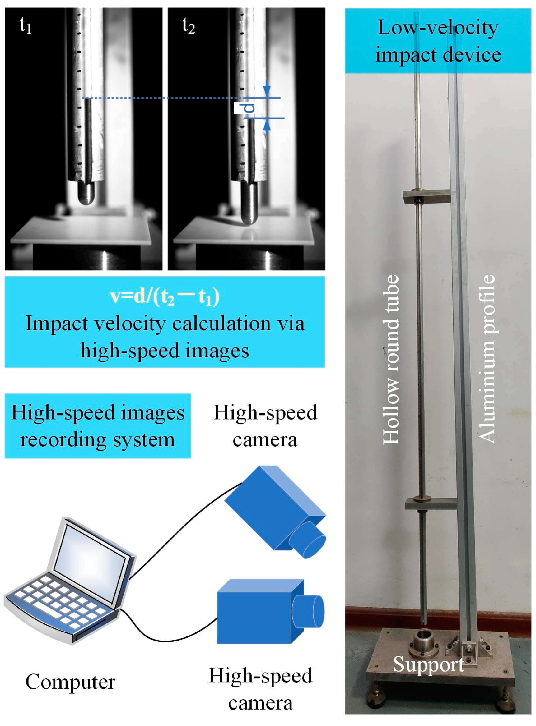
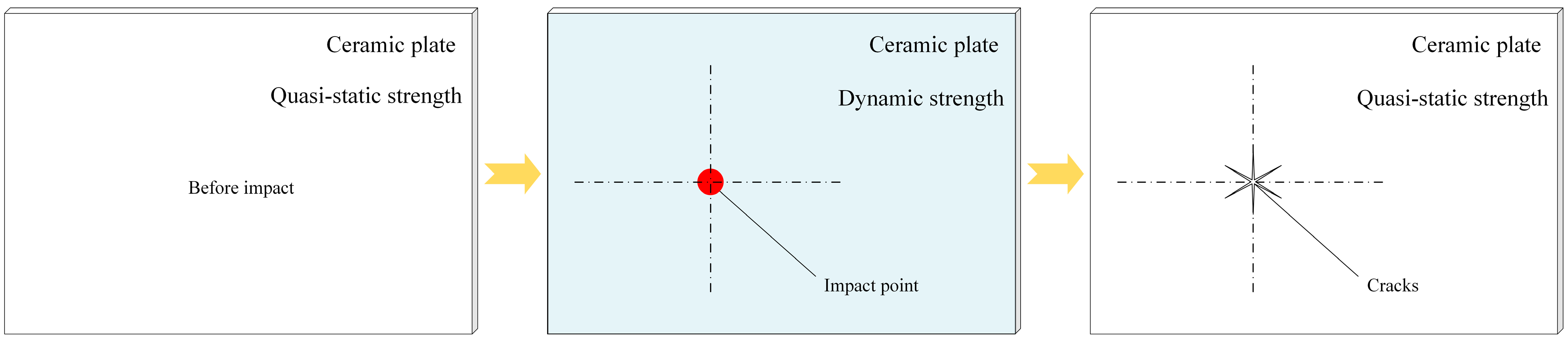
2.2. Drop-Impact Test

A low-velocity drop-impact device consisting of an aluminum profile, a hollow round tube, and a steel support was designed and manufactured for structural impact tests on AlN plates, as shown in Figure 3. The spherical-nosed steel impactor weighed 32.4 g and was placed in the hollow round tube. The dimensions of the specimens were 70 mm × 70 mm × 2 mm, and the diameter of the support ring was 50 mm. Different impact velocities can be achieved by raising the impactor to different heights before allowing it to fall freely. A high-speed camera was used for horizontal observations to calculate the impact velocity of the spherical-nosed steel impactor. The other high-speed camera was used to capture the impact process and failure modes of the AlN plates. Seven repeated impact tests with different impact velocities were conducted, and the results are presented in Table 2. According to the sample status after tests, the critical impact velocity ranged between 1.24 and 1.46 m/s.

3. Numerical Analysis and Validation

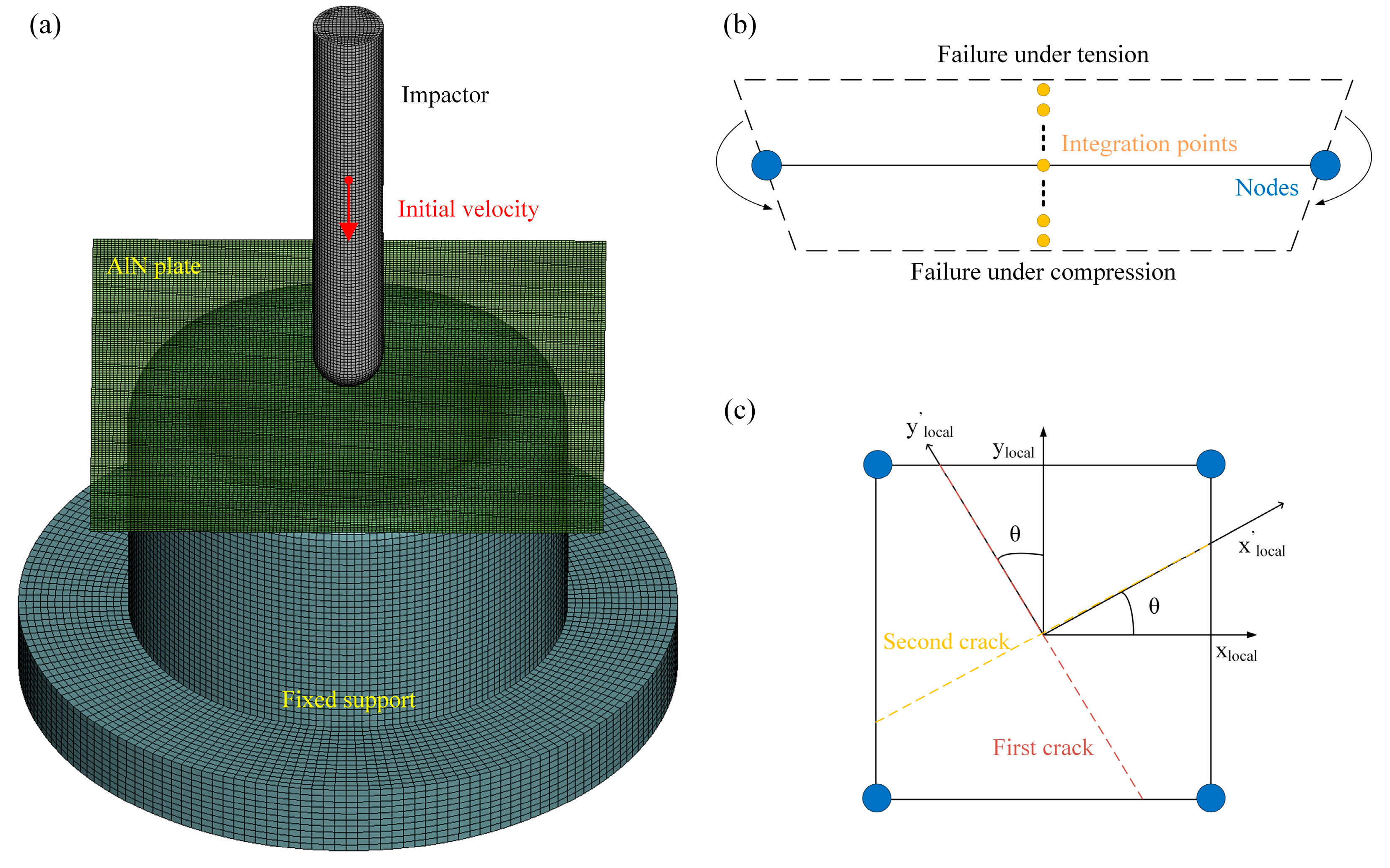
3.1. Smeared Fixed-Crack Model

The numerical model for an impact analysis of the AlN plates is shown in Figure 4a, and the plate is described using a smeared fixed-crack model. Shell elements are typically used for the simulation of thin-walled structures. Several integration points can be defined along the thickness direction and thus the elements are assigned with proper bending stiffness, as illustrated in Figure 4b. Nine integration points were positioned in the thickness direction after a detailed calibration process. The fracture-property definition of smeared fixed-crack model is illustrated in Figure 4c. In the smeared fixed-crack model, the element exhibited linearly elastic isotropic mechanical behavior before fracture [36]. When the stress-state-dependent failure threshold was reached, a crack was initiated perpendicular to the maximum principal stress direction. This implies that a crack coordinate system defined by the relative angle with respect to the local-element coordinate system xlocal-ylocal was established and stored [37]. An element containing a crack can withstand compressive and tensile loads parallel to the crack direction. A second crack orthogonal to the first crack is possible, and it can open and close independently of the first crack, corresponding to the new local-element coordinate system x’local-y’local in the figure. The angle between the second coordinate system and the first coordinate system is θ. The first crack and second crack were shown in the figure as dash lines with different colors. This model has been implemented in the commercial software LS-DYNA R12 recently [21]. As a newly proposed numerical technique, this method is being refined and developed every year and the latest version is released in LS-DYNA R15.
Three different failure criteria were used for the impact response prediction of the AlN plates, as shown in Figure 5a–c. These models can be expressed by principal stresses σ 1 and σ 2 , tensile strength FT, and compressive strength FC, as follows.
(a) Rankine maximum stress
F C < σ 1 , σ 2 < F T
(b) Mohr–Coulomb
m a x σ 1 F T , σ 2 F T < 1 ,                       i f   σ 1 > 0   a n d   σ 2 > 0 m a x σ 1 F C , σ 2 F C < 1 ,       i f   σ 1 < 0   a n d   σ 2 < 0 σ 1 F T σ 2 F T < 1 ,                                           i f   σ 1 > 0   a n d   σ 2 < 0 σ 1 F C + σ 2 F T < 1 ,                                   i f   σ 1 < 0   a n d   σ 2 > 0
(c) Drucker–Prager
1 2 F C F C F T 1 σ 1 + σ 2 + F C F T + 1 σ 1 2 + σ 2 2 σ 1 σ 2 < 1
As shown in Figure 5d, the failure envelopes of the Rankine and Mohr–Coulomb criteria coincided in the first quadrant. The envelope of the Drucker–Prager model was inside the Rankine and Mohr–Coulomb envelopes.
In this study, FT was set to 349.0 MPa obtained from the quasi-static tests. The compression tests on AlN were not conducted in this work. The compressive strength of AlN has been reported by different researchers, i.e., 2.5 GPa [38], 2.81 GPa [39], and 3.3 GPa [40] for a quasi-static loading condition. FC was then set as 3 GPa based on these reported data. Actually, the fracture behavior of the AlN plate is mainly governed by its tensile properties. Different values of FC around 3 GPa have been tried and show little difference for the numerical results. The description of the rate effect of brittle materials in numerical models is still an open topic in recent studies [41,42,43,44]. A scale factor, FTSCL, can be further defined in the smeared fixed-crack model to consider the rate-dependent tensile strength, based on the assumption that a significantly higher tensile strength would be applied to the ceramic plate during impact events. The modified tensile strength can be expressed as follows.
F T m o d = F T S C L × F T
There are two approaches to define the tensile strength after the first crack in a smeared fixed-crack model. The first one is that the tensile strength drops to its original value, FT, as soon as the first crack happens in the associated part. In this case, FTSCL > 1 can be helpful to model high force peaks in impact events. Alternatively, when a crack forms in a neighboring element, the tensile strength for an element is evaluated depending on the smoothed effective strain rate. These two approaches have been compared by the authors in detail [19]. It was found that during the post-fracture process, the second approach overestimated the material strength with a delayed crack-propagation process for quite brittle materials. Thus, the first approach was used in present study. The application of rate-dependent flexural strength in the present model is illustrated in Figure 6. Because the drop-impact velocity was close to the loading velocity of the three-point bending tests, the FTSCL was set to 1.13, based on the ratio of the dynamic and quasi-static flexural strengths of the AlN specimens. All the material parameters used in the proposed numerical models are summarized in Table 3.

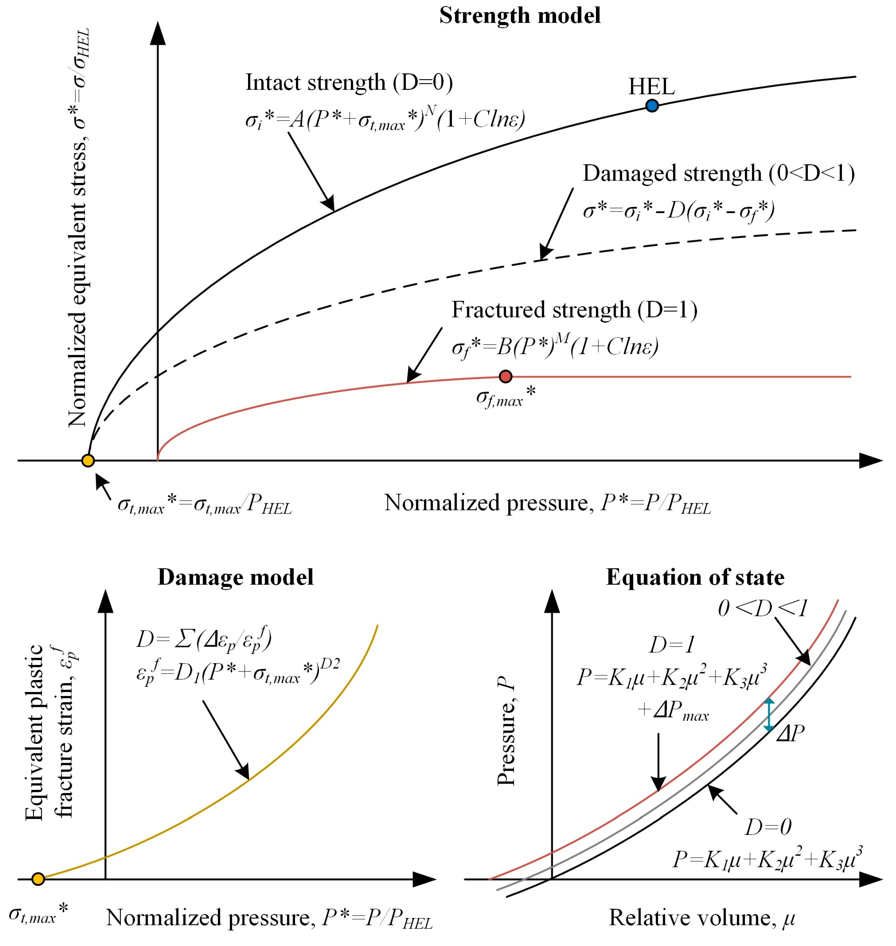
3.2. Failure Prediction of AlN Substrates Under Low-Velocity Impact Loads

A comparison between the experimental data and the numerical results is shown in Figure 7. The experimental results showed that the AlN plate did not fail when the impact velocity was lower than 1.24 m/s but failed when the impact velocity was higher than 1.46 m/s. The three velocity regions are represented by different colors in Figure 7. The numerical results were obtained by the bisection method and the critical velocity was accurate within 0.05 mm. Similar simulation results were obtained when the Rankine maximum stress and Mohr–Coulomb criteria were used. This is because the failure envelopes of the Rankine and Mohr–Coulomb criteria coincided in the first quadrant, and a tensile-induced fracture was the main failure mode of the specimen under this low-velocity impact-loading condition. The critical velocities predicted using the Rankine and Mohr–Coulomb criteria were higher than the experimental values, and the critical velocity predicted using the Drucker–Prager criterion was lower than the experimental data. After considering the rate-dependent tensile strength by defining the FTSCL value, the critical velocity predicted by the Rankine and Mohr–Coulomb criteria were significantly higher, and the critical velocity predicted by the Drucker–Prager criterion fell well within the experimental critical velocity region. Thus, the Drucker–Prager criterion with a scaled tensile strength can satisfactorily analyze the low-velocity impact response of ceramic plates.
The tensile strength FT was obtained based on three-point bending tests, which constitute the uniaxial flexural testing method. The three-point bending test is a common testing method for the flexural-strength evaluation of brittle materials. During tests, the lower surface of the specimen is under uniaxial tensile stress, corresponding to the points at which the envelopes cross the axis, as shown in Figure 5d. However, for the proposed low-velocity impact tests, the lower surface of the AlN plate is under biaxial tensile loading, corresponding to the points at which the envelopes crossed the dotted line shown in Figure 5d. The difference between uniaxial and biaxial flexural strength of AlN ceramic is still not reported in the present literature. According to Figure 5d, the Rankine and Mohr–Coulomb criteria define an envelope, assuming that the biaxial tensile strength is the same as the uniaxial tensile strength. The Drucker–Prager criterion defines an arc-shaped envelope, indicating that the biaxial tensile strength is lower than the uniaxial tensile strength. Based on the simulation results presented in Figure 7, the Drucker–Prager criterion can precisely describe the failure envelope of the AlN plates under biaxial loads.
The observed and simulated failure modes of the AlN plates at different impact velocities are shown in Figure 8. The selected Drucker–Prager criterion with a scaled tensile strength was used in the numerical model. Multiple radial cracks appeared on the plate, and more cracks were observed with an increase in impact velocity to dissipate more impact energy. The replicated numerical cracks propagated not only along the mesh geometry direction, but also along other directions thanks to the independent orthogonal cracks existing in each shell element. The failure modes of the specimens under different impact velocities were replicated well by the proposed numerical model.
The cracked pieces of specimens were collected for further analysis after tests. It can be seen from Figure 9 that the number of cracks in the specimens increased with the increase in impact velocity as well as the impact energy. More cracks were generated to dissipate more impact energy. When the impact velocity of the impactor increased to 4.29 m/s, a conical fracture surface can be identified at the impact region due to the increasing contact force [45]. The crack pattern of AlN substrates can be further shown in the post-processing software LS-PREPOST 4.9. Figure 9 provides the crack information of the shell elements, in which blue elements contain no crack, green elements contain one single crack, and red elements contain two orthogonal cracks. No elements fail due to compression loads. It can be seen that the red elements are predominantly distributed in the vicinity of the loading site. This is because the center of the plate is under equi-biaxial bending stress conditions during the loading process. Also, it can be seen that the simulated crack numbers are exactly the same as experimental observations, proving the validity of the proposed numerical model again.
Figure 10 represents the global x-coordinate of the first crack direction for the numerical specimen impacted at 4.29 m/s. These coordinates can be used to represent the crack as a vector, such as in LS-PREPOST with Post→Vector→Hist. var. cosine. Thus, the values of the elements represent the cosine of the angle between x-axis and first crack direction. It can be seen that the crack direction in each element is substantially coincident with the macroscopic crack-propagation direction. The crack indication technique is a unique progress for the proposed smeared fixed-crack model, which improves the adequate analysis of brittle fracture problems and is impossible with the element erosion technique in traditional FEM models.

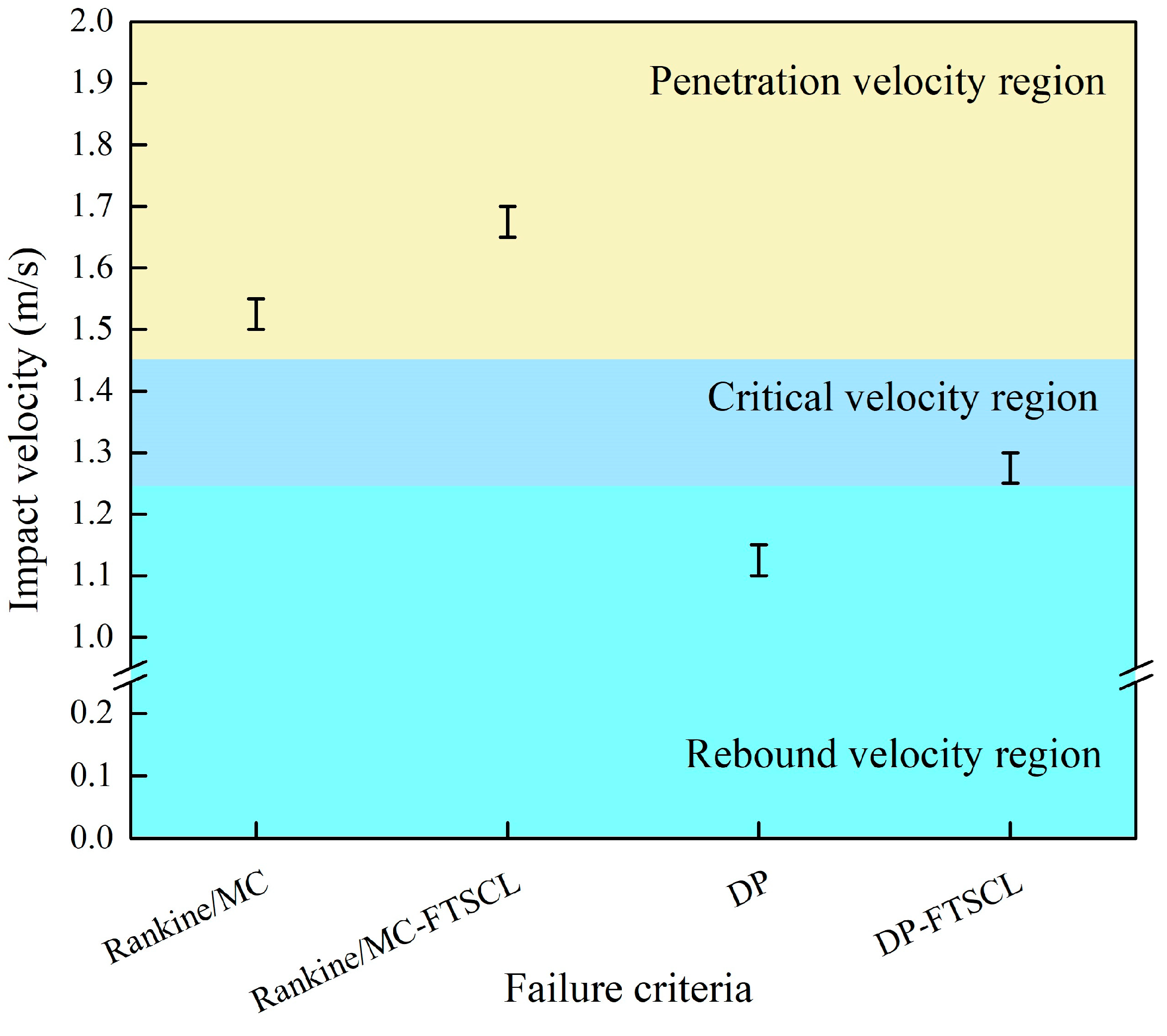
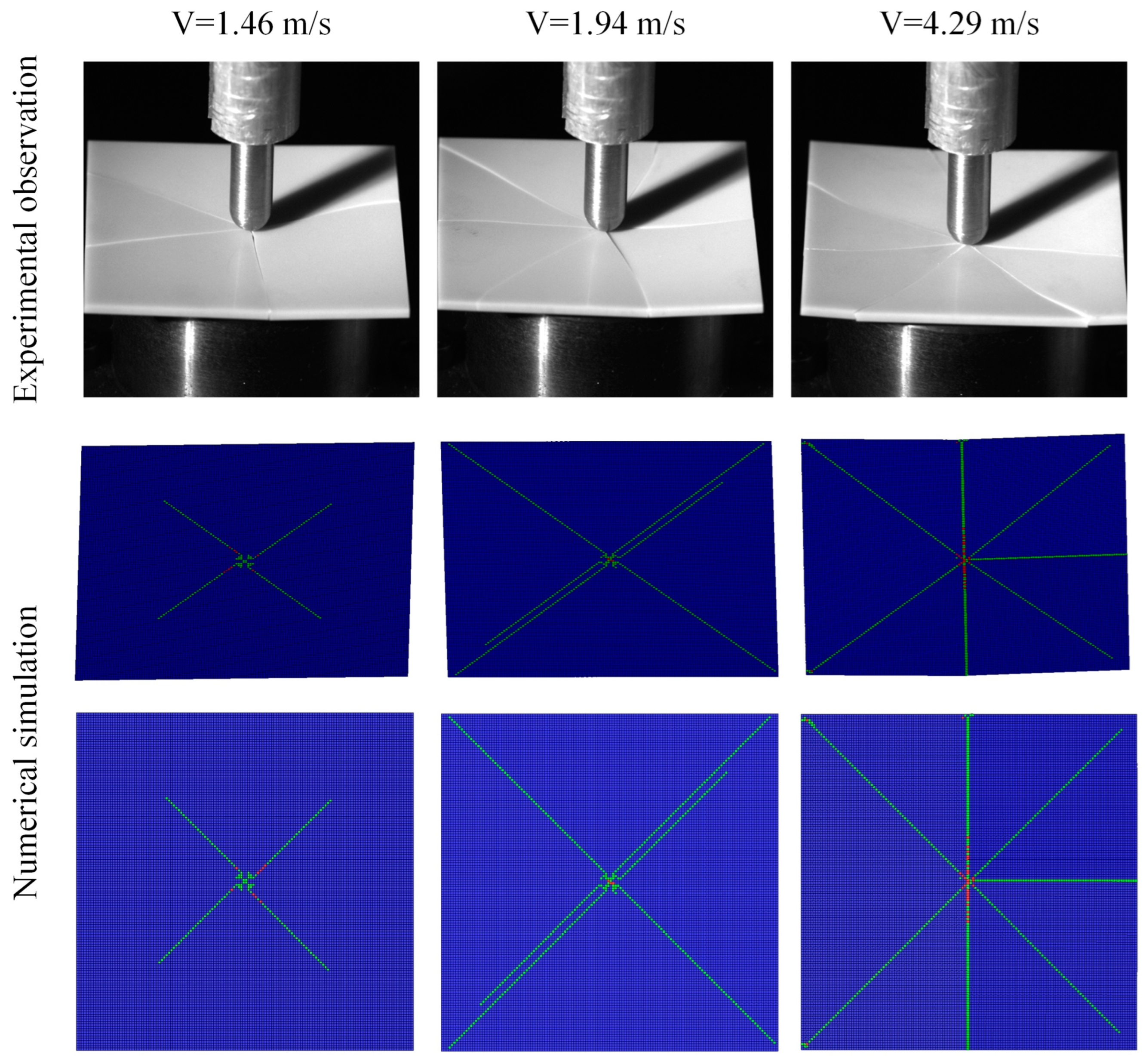
3.3. Comparison and Discussions

Classical numerical models for brittle materials primarily focus on the compression-rate effect of materials. These models provide accurate numerical results for high-velocity impact cases [46,47,48]. The most popular constitutive model for a large amount of strain, a high strain rate, and high-pressure applications is the Johnson–Holmquist II (JH-2) model [49], as shown in Figure 11. The JH-2 constants for AlN have also been determined by Holmquist based on multiple rate-dependent tests and validated by various plate-impact and ballistic experiments [26]. In this study, the JH-2 model together with calibrated parameters (Table 4) for AlN was utilized for low-velocity impact simulation, for comparison with the developed smeared fixed-crack model.
Numerical models utilizing JH-2 material model were built and calculated. The critical velocity range predicted by JH-2 model is 2.85–2.9 m/s and the comparison with experimental tests as well as the smeared fixed-crack model is listed in Table 5. It can be seen that the JH-2 model with parameters mainly focusing on high-strain rate and high-pressure properties will significantly overestimate the low-velocity impact resistance of AlN ceramic plates. This will give rise to safety issues in the structural design.
The failure modes of the ceramic plate impacted at the velocity of 4.29 m/s were further compared, as shown in Figure 12. The ceramic plates’ back views were provided for numerical models. Thanks to the definition of crack directions in the smeared fixed-crack model, radial cracks along different directions were generated freely without any preset crack paths. For the JH-2 model, the cracks were presented based on element erosion, which is related to the element geometry and arrangement. Thus, only cross cracks can be obtained for this structured hexahedron mesh type. It is a fact that a crack in a ceramic plate immediately runs through the thickness due to the low crack-growth toughness. In a smeared fixed-crack model, if the critical number of failed integration points in one element is reached, all integration points over the element thickness fail as well. This critical number was set as one in this model and the simulated cracks were comparable to experimental observations. For the JH-2 model, the cracks initiated from the back side of the specimen and propagated to the impact side. The bending stiffness and back elements’ tensile stress decreased during this process, resulting in an incomplete fracture mode with some elements remaining along the cracks. The limitations and drawbacks of the JH-2 model in modeling the quasi-static or tensile-stress-dominated fracture behavior of brittle materials have also been reported in several recent studies [50,51]. Thus, the proposed smeared fixed-crack model with rate-dependent flexural strength data is an efficient and accurate method for a low-velocity impact response analysis of ceramic structures.
In conclusion, the effect of brittle materials’ rate-dependent flexural or tensile strength has received limited attention in previous numerical models. This study demonstrates that rate-dependent flexural and tensile strengths are essential for the low-velocity impact–response analysis of ceramic structures. A novel experimental technique can be developed to obtain the flexural and tensile mechanical behavior of brittle materials over a wide range of loading rates. A smeared fixed-crack model was then developed, considering rate-dependent flexural strength. This model shows unique strength for low-velocity impact issues in both the qualitative analysis of ceramic failure modes and the quantitative analysis of critical velocity aspects.

4. Parametric Study

After being validated by low-velocity impact tests, the proposed smeared-fixed crack model with rate-dependent flexural strength data was further utilized for parametric study. The effect of impactor nose shape and deflection angles were investigated to better illustrate the low-velocity impact response of AlN ceramic substrates.

4.1. Effect of the Impactor Nose Shape

The high-velocity impact response of targets penetrated by different nose projectiles has been reported, especially for ceramic [48,52], composite [53,54], and metal [55,56] targets. The projectile nose-shape effect on the low-velocity impact response of ceramics is still limited and thus conducted in this study. Spherical and flat-nosed projectiles with the same diameter of 9.6 mm and weight of 32.4 g were built in numerical models, as shown in Figure 13a. The same AlN target was applied here. Based on the bisection method, the critical velocity range was 2.00–2.05 m/s for the flat-nosed projectile, while the range was 1.25–1.30 m/s for the spherical-nosed projectile. With the same impact velocity and impact energy, a remarkable increase of 58.8% for critical velocity and 152.2% for critical energy was obtained for the flat-nosed projectile compared to the spherical-nosed projectile. Figure 13b,c shows the failure mode of ceramic plates impacted by spherical and flat-nosed projectiles. A larger cracked area in the impact region can be seen for the ceramic plate impacted by the flat-nosed projectile. For the spherical and flat-nosed projectile, the initial contact with targets are point–surface contact and surface–surface contact, respectively. The increase in contact area will decrease the local contact stress and improve the low-velocity impact resistance of AlN plates.
The comparison of the ceramic plates’ maximum principal-stress-field evolution is shown in Figure 14. The moment before the impactor made contact with the ceramic plate is recognized as t = 0 μs. A smaller area of stress concentration was shown for the sphere-nose impact condition. For the flat-nosed projectile, the ceramic plate failed at 40 μs, while the ceramic plate failed at 70 μs for the sphere-nosed projectile. This is due to the smaller contact stiffness between the sphere-nosed projectile and ceramic plate.

4.2. Effect of the Impactor Deflection Angles

The impact response of ceramic tiles with different impactor deflection angles was further investigated. As shown in Figure 15, the impact velocity was in the same direction as the axis of the projectiles. The impactor deflection angle was defined as the angle between the axis of the target and the impact velocity direction.
Deflection angles of 2°, 4°, and 6° were selected for model building and calculating. The critical impact velocity range for spherical and flat-nosed projectiles with different deflection angles is shown in Figure 16. For the spherical-nosed projectile, a small deflection angle has little influence on the critical impact velocity. For the flat-nosed projectile, the critical impact velocity decreases remarkably for non-vertical impact conditions. The values decrease to the same level as the spherical-nosed projectile’s impact condition. When there is a deflection angle for flat-nosed projectiles, the initial contact type between projectile and target will transfer to point–surface contact, which is the same as the spherical-nosed projectile. It also should be noted that the critical impact velocity increases slightly when the deflection angle increases to 6°. This is mainly due to the velocity component perpendicular to the target plate, which decreases with the increase in deflection angles.
The failure modes of AlN ceramic plates impacted by the flat-nosed projectile under different impact velocities with a deflection angle of 2° are shown in Figure 17. It can be seen that the oblique impact response of the AlN plate is totally different compared to the vertical impact response shown in Figure 13c. Multiple radial cracks appear on the plate, similar to the spherical-nosed projectile’s impact condition. More cracks can be observed with the increase in impact velocity.

5. Conclusions

In order to improve the reliability of the ceramic-packaging electronic structures for aerospace applications, quasi-static and dynamic flexural tests were conducted to determine the rate-dependent flexural strengths of the AlN ceramics. The average dynamic flexural strength significantly increased by 12.9% compared with that of the quasi-static loading condition. The low-velocity impact response of AlN substrates was predicted using the proposed smeared fixed-crack numerical model. A detailed comparison with the experimental results showed that the critical velocity of the impactor and the failure mode of the plate can be accurately predicted using the Drucker–Prager criterion with the scaled fracture-strength parameter. Rate-dependent flexural and tensile strengths in numerical models are essential for a low-velocity impact–response analysis of ceramic structures. The radial cracks on the ceramic plate upon impact were reproduced well using the proposed novel numerical technique. This model shows unique strength for low-velocity impact issues in both the qualitative analysis of ceramic failure modes and the quantitative analysis of critical velocity aspects over the classical JH-2 model.
Parametric studies show that ceramic tiles possess better low-velocity impact resistance to the flat-nosed projectile due to the increase in contact area. For thee spherical-nosed projectile, a small deflection angle has little influence on the critical impact velocity. For the flat-nosed projectile, the critical impact velocity decreases remarkably for non-vertical impact conditions due to the change in initial contact condition. This study achieves the prediction of low-speed impact response for AlN ceramic structures based on dynamic flexural tests on brittle materials and the developed smeared fixed-crack model, thereby providing technical support for the impact reliability analysis of aerospace ceramic-packaging devices.

Author Contributions

Methodology, Z.W.; Software, Z.W.; Validation, Z.W.; Formal analysis, Y.L.; Writing—original draft, Z.W.; Writing—review and editing, Y.L.; Funding acquisition, Z.W. and Y.L. All authors have read and agreed to the published version of the manuscript.

Funding

Support from the National Natural Science Foundation of China (12402447, 12202282), Beijing Natural Science Foundation (3244028), and R&D Program of the Beijing Municipal Education Commission (KM202410005038) is gratefully acknowledged.

Data Availability Statement

Data are contained within the article.

Conflicts of Interest

The authors declare no conflicts of interest.

Nomenclature

σ f Flexural strength;
F m a x Failure load;
L, b, hSpan length, width and thickness of the sample;
ε I t ,   ε R t , ε T t Incident, reflection and transmission strain signal;
u(t), V(t)Loading displacement and loading speed;
C0Longitudinal elastic wave velocity of the loading bar;
E, AYoung’s modulus and cross-section area of the bars;
PI, PTForce history from loading side and supporting side;
σ1, σ2Principal stresses in the shell elements;
νPoisson’s ratio;
FCCompressive strength;
FTQuasi-static tensile strength;
FTmodModified dynamic tensile strength;
FTSCLScale factor for dynamic tensile strength;
AlNAluminum nitride;
MEMSMicro-electro mechanical systems;
FEMFinite-element method;
SHPBSplit Hopkinson pressure bar;
JH-2Johnson–Holmquist II;
MCMohr–Coulomb;
DPDrucker–Prager.

References

  1. Zagorac, D.; Zagorac, J.; Djukic, M.B.; Jordanov, D.; Matović, B. Theoretical study of AlN mechanical behaviour under high pressure regime. Theor. Appl. Fract. Mech. 2019, 103, 102289. [Google Scholar] [CrossRef]
  2. Baek, S.-H.; Jeong, H.; Ryu, S.-S. AlN with high strength and high thermal conductivity based on an MCAS-Y2O3-YSZ multi-additive system. J. Eur. Ceram. Soc. 2022, 42, 898–904. [Google Scholar] [CrossRef]
  3. Fattahi, M.; Vaferi, K.; Vajdi, M.; Moghanlou, F.S.; Namini, A.S.; Asl, M.S. Aluminum nitride as an alternative ceramic for fabrication of microchannel heat exchangers: A numerical study. Ceram. Int. 2020, 46, 11647–11657. [Google Scholar] [CrossRef]
  4. Chen, G.-R.; Lin, K.-L.; Lin, C.-C. Aging effect on high heat dissipation DBA and DBAC substrates for high power electronics. Ceram. Int. 2022, 48, 28889–28897. [Google Scholar] [CrossRef]
  5. Hung, S.-W.; Chen, T.-K. Disclosing AlN ceramic substrate process failure mode and effect analysis. Microelectron. Reliab. 2019, 103, 113508. [Google Scholar] [CrossRef]
  6. Luo, H.; Li, Y.; Fan, C.; Wu, X.; Liu, G. Design and experimental research on buffer protection of high-g penetrator for deep space exploration. Acta Astronaut. 2021, 189, 63–78. [Google Scholar] [CrossRef]
  7. Zhang, X.-H.; Li, J.-Z.; Qin, F.; Wang, L. Experiments and numerical simulations of microelectronic devices subjected to multipoint impact loading. Microelectron. Reliab. 2021, 127, 114408. [Google Scholar] [CrossRef]
  8. Ji, M.; Li, H.; Zheng, J.; Yang, S.; Zaiemyekeh, Z.; Hogan, J.D. An experimental study on the strain-rate-dependent compressive and tensile response of an alumina ceramic. Ceram. Int. 2022, 48, 28121–28134. [Google Scholar] [CrossRef]
  9. Jia, X.-T.; Zhang, Z.-H.; Li, X.-Y.; Liu, L.-J.; Wang, Q.; He, Y.-Y.; Feng, X.-X.; Liu, Y.; Sun, Y.-H.; Cheng, X.-W. Compressive properties and failure mechanisms of AlON ceramics under different strain rates. Ceram. Int. 2024, 50, 12787–12801. [Google Scholar] [CrossRef]
  10. Venkatesan, J.; Iqbal, M.A.; Madhu, V. Experimental and numerical study of the dynamic response of B4C ceramic under uniaxial compression. Thin Walled Struct. 2020, 154, 106785. [Google Scholar] [CrossRef]
  11. Song, Q.; Cheng, Z. Dynamic response of the TiB2–SiC/B4C composite ceramic under dynamic loading. Int. J. Appl. Ceram. Technol. 2023, 20, 2511–2521. [Google Scholar] [CrossRef]
  12. Iqbal, M.A.; Khan, M.K. Failure pattern in ceramic metallic target under ballistic impact. Def. Technol. 2024, 40, 173–190. [Google Scholar] [CrossRef]
  13. An, R.; Wang, Y.; Bao, J.; Jiang, B.; Cheng, H.; Cheng, X.; Wang, F. Predicting ballistic resistance based on the mechanical properties of armored ceramics. J. Mater. Res. Technol. 2024, 32, 2370–2385. [Google Scholar] [CrossRef]
  14. Bresciani, L.M.; Manes, A.; Giglio, M. An analytical model for ballistic impacts against ceramic tiles. Ceram. Int. 2018, 44, 21249–21261. [Google Scholar] [CrossRef]
  15. Wang, X.-E.; Yang, J.; Liu, Q.-F.; Zhang, Y.-M.; Zhao, C. A comparative study of numerical modelling techniques for the fracture of brittle materials with specific reference to glass. Eng. Struct. 2017, 152, 493–505. [Google Scholar] [CrossRef]
  16. Fan, Y.; You, H.; Tian, X.; Yang, X.; Li, X.; Prakash, N.; Yu, Y. A meshfree peridynamic model for brittle fracture in randomly heterogeneous materials. Comput. Methods Appl. Mech. Eng. 2022, 399, 115340. [Google Scholar] [CrossRef]
  17. Wang, Z.; Ma, D.; Suo, T.; Li, Y.; Manes, A. Investigation into different numerical methods in predicting the response of aluminosilicate glass under quasi-static and impact loading conditions. Int. J. Mech. Sci. 2021, 196, 106286. [Google Scholar] [CrossRef]
  18. Kim, H.-S.; Ha, B.-K.; Yoo, B.-Y.; Jeong, H.-S.; Park, S.-H. Numerical prediction of dynamic fracture strength of edge-mounted non-symmetric tempered glass panels under steel ball drop impact. J. Mater. Res. Technol. 2022, 17, 270–281. [Google Scholar] [CrossRef]
  19. Wang, Z.; Ma, D.; Qin, F. Smeared fixed crack model for quasi-static and dynamic biaxial flexural response analysis of aluminosilicate glass plates. Thin Walled Struct. 2024, 205, 112533. [Google Scholar] [CrossRef]
  20. Zemanová, A.; Hála, P.; Konrád, P.; Sovják, R.; Šejnoha, M. Gradual fracture of layers in laminated glass plates under low-velocity impact. Comput. Struct. 2023, 283, 107053. [Google Scholar] [CrossRef]
  21. Zemanová, A.; Hála, P.; Konrád, P.; Šejnoha, M. Smeared Fixed Crack Model for Numerical Modelling of Glass Fracture in LS-DYNA. In AIP Conference Proceedings; AIP Publishing: Melville, NY, USA, 2023. [Google Scholar] [CrossRef]
  22. Hála, P.; Zemanová, A.; Zeman, J.; Šejnoha, M. Numerical study on failure of laminated glass subjected to low-velocity impact. Glas. Struct. Eng. 2023, 8, 99–117. [Google Scholar] [CrossRef]
  23. Hogan, J.D.; Farbaniec, L.; Sano, T.; Shaeffer, M.; Ramesh, K.T. The effects of defects on the uniaxial compressive strength and failure of an advanced ceramic. Acta Mater. 2016, 102, 263–272. [Google Scholar] [CrossRef]
  24. Huang, J.Y.; Lin, C.K.; Bian, Y.L.; Xie, H.L.; Chai, H.W.; Ding, Y.Y.; Luo, S.N. Strain rate effects on fragment morphology of ceramic alumina: A synchrotron-based study. Int. J. Mech. Sci. 2024, 280, 109506. [Google Scholar] [CrossRef]
  25. Zhang, X.; Zou, Y.; Hao, H.; Li, X.; Ma, G.; Liu, K. Laboratory test on dynamic material properties of annealed float glass. Int. J. Prot. Struct. 2012, 3, 407–430. [Google Scholar] [CrossRef]
  26. Holmquist, T.J.; Templeton, D.W.; Bishnoi, K.D. Constitutive modeling of aluminum nitride for large strain, high-strain rate, and high-pressure applications. Int. J. Impact Eng. 2001, 25, 211–231. [Google Scholar] [CrossRef]
  27. Islam, M.R.I.; Zheng, J.Q.; Batra, R.C. Ballistic performance of ceramic and ceramic-metal composite plates with JH1, JH2 and JHB material model. Int. J. Impact Eng. 2020, 137, 103469. [Google Scholar] [CrossRef]
  28. Baranowski, P.; Kucewicz, M.; Gieleta, R.; Stankiewicz, M.; Konarzewski, M.; Bogusz, P.; Pytlik, M.; Małachowski, J. Fracture and fragmentation of dolomite rock using the JH-2 constitutive model: Parameter determination, experiments and simulations. Int. J. Impact Eng. 2020, 140, 103543. [Google Scholar] [CrossRef]
  29. Zhang, X.; Hao, H.; Ma, G. Dynamic material model of annealed soda-lime glass. Int. J. Impact Eng. 2015, 77, 108–119. [Google Scholar] [CrossRef]
  30. Meyland, M.J.; Bønding, C.K.T.; Eriksen, R.N.W.; Nielsen, J.H. An experimental investigation of the flexural strength of soda–lime–silica glass at high loading rates. Glas. Struct. Eng. 2019, 4, 175–183. [Google Scholar] [CrossRef]
  31. Cheng, M.; Chen, W.; Sridhar, K.R. Experimental method for a dynamic biaxial flexural strength test of thin ceramic substrates. J. Am. Ceram. Soc. 2002, 85, 1203–1209. [Google Scholar] [CrossRef]
  32. Nie, X.; Chen, W.W.; Wereszczak, A.A.; Templeton, D.W. Effect of loading rate and surface conditions on the flexural strength of borosilicate glass. J. Am. Ceram. Soc. 2009, 92, 1287–1295. [Google Scholar] [CrossRef]
  33. Quinn, G.D.; Morrell, R. Design Data for Engineering Ceramics: A Review of the Flexure Test. J. Am. Ceram. Soc. 1991, 74, 2037–2066. [Google Scholar] [CrossRef]
  34. Wang, Z.; Suo, T.; Sheikh, M.Z.; Li, Y.; Wang, X.; Wang, Y. Quasi-static and dynamic flexural behavior of annealed and chemically strengthened aluminosilicate glass with notch defects. J. Non Cryst. Solids 2019, 521, 119479. [Google Scholar] [CrossRef]
  35. Wang, Z.; Ren, T.; Sang, S.; Qin, F.; Zhang, C. Experimental and numerical investigation on the discrete fracture property and dynamic flexural response of aluminum nitride ceramics. Eng. Fract. Mech. 2024, 308, 110384. [Google Scholar] [CrossRef]
  36. Wang, Z.; Manes, A. Stress analysis and fracture simulation of aluminosilicate glass plates under Ring-On-Ring loading. Forces Mech. 2021, 5, 100047. [Google Scholar] [CrossRef]
  37. Pelfrene, J.; Kuntsche, J.; Van Dam, S.; Van Paepegem, W.; Schneider, J. Critical assessment of the post-breakage performance of blast loaded laminated glazing: Experiments and simulations. Int. J. Impact Eng. 2016, 88, 61–71. [Google Scholar] [CrossRef]
  38. Chen, W.; Ravichandran, G. Static and dynamic compressive behavior of aluminum nitride under moderate confinement. J. Am. Ceram. Soc. 1996, 79, 579–584. [Google Scholar] [CrossRef]
  39. Subhash, G.; Ravichandran, G. Mechanical behaviour of a hot pressed aluminum nitride under uniaxial compression. J. Mater. Sci. 1998, 33, 1933–1939. [Google Scholar] [CrossRef]
  40. Hu, G.; Ramesh, K.T.; Cao, B.; McCauley, J.W. The compressive failure of aluminum nitride considered as a model advanced ceramic. J. Mech. Phys. Solids 2011, 59, 1076–1093. [Google Scholar] [CrossRef]
  41. Osnes, K.; Hopperstad, O.S.; Børvik, T. Rate dependent fracture of monolithic and laminated glass: Experiments and simulations. Eng. Struct. 2020, 212, 110516. [Google Scholar] [CrossRef]
  42. Zaiemyekeh, Z.; Li, H.; Sayahlatifi, S.; Ji, M.; Zheng, J.; Romanyk, D.L.; Hogan, J.D. Computational finite element modeling of stress-state- and strain-rate-dependent failure behavior of ceramics with experimental validation. Ceram. Int. 2023, 49, 13878–13895. [Google Scholar] [CrossRef]
  43. Tan, S.; Long, S.; Yao, X.; Zhang, X. An improved material model for loading-path and strain-rate dependent strength of impacted soda-lime glass plate. J. Mater. Res. Technol. 2021, 15, 1905–1919. [Google Scholar] [CrossRef]
  44. Ma, D.; Wang, Z.; Giglio, M.; Amico, S.C.; Manes, A. Influence of strain-rate related parameters on the simulation of ballistic impact in woven composites. Compos. Struct. 2022, 300, 116142. [Google Scholar] [CrossRef]
  45. Simons, E.C.; Weerheijm, J.; Toussaint, G.; Sluys, L.J. An experimental and numerical investigation of sphere impact on alumina ceramic. Int. J. Impact Eng. 2020, 145, 103670. [Google Scholar] [CrossRef]
  46. Bresciani, L.M.; Manes, A.; Romano, T.A.; Iavarone, P.; Giglio, M. Numerical modelling to reproduce fragmentation of a tungsten heavy alloy projectile impacting a ceramic tile: Adaptive solid mesh to the SPH technique and the cohesive law. Int. J. Impact Eng. 2016, 87, 3–13. [Google Scholar] [CrossRef]
  47. Wang, Z.; Ren, T.; Suo, T.; Manes, A. Quasi-static and low-velocity impact biaxial flexural fracture of aluminosilicate glass—An experimental and numerical study. Thin Walled Struct. 2021, 165, 107939. [Google Scholar] [CrossRef]
  48. Wang, Z.; Li, Y.; Ma, D.; Wang, X.; Li, Y.; Suo, T.; Manes, A. Experimental and numerical investigation on the ballistic performance of aluminosilicate glass with different nosed projectiles. Ceram. Int. 2023, 49, 17729–17745. [Google Scholar] [CrossRef]
  49. Johnson, G.R.; Holmquist, T.J. An improved computational constitutive model for brittle materials. In AIP Conference Proceedings; AIP Publishing: Melville, NY, USA, 1994; Volume 309, pp. 981–984. [Google Scholar]
  50. Simons, E.C.; Weerheijm, J.; Sluys, L.J. A viscosity regularized plasticity model for ceramics. Eur. J. Mech. A Solids 2018, 72, 310–328. [Google Scholar] [CrossRef]
  51. Baranowski, P.; Kucewicz, M.; Janiszewski, J. JH-2 constitutive model of sandstone for dynamic problems. Sci. Rep. 2024, 14, 3339. [Google Scholar] [CrossRef]
  52. Fadhil, B.M. Ballistic impact on ceramic armour with different nosed projectiles: Numerical study. Int. J. Mech. Mater. Eng. 2012, 7, 69–77. [Google Scholar]
  53. Zhu, Q.; Zhang, C.; Curiel-Sosa, J.L.; Bui, T.Q.; Xu, X. Finite element simulation of damage in fiber metal laminates under high velocity impact by projectiles with different shapes. Compos. Struct. 2019, 214, 73–82. [Google Scholar] [CrossRef]
  54. Ansari, M.M.; Chakrabarti, A. Influence of projectile nose shape and incidence angle on the ballistic perforation of laminated glass fiber composite plate. Compos. Sci. Technol. 2017, 142, 107–116. [Google Scholar] [CrossRef]
  55. Gupta, N.K.; Iqbal, M.A.; Sekhon, G.S. Effect of projectile nose shape, impact velocity and target thickness on deformation behavior of aluminum plates. Int. J. Solids Struct. 2007, 44, 3411–3439. [Google Scholar] [CrossRef]
  56. Walker, J.D.; Anderson, C.E., Jr. The influence of initial nose shape in eroding penetration. Int. J. Impact Eng. 1994, 15, 139–148. [Google Scholar] [CrossRef]
Figure 1. (a) Schematic of three-point bending tests; (b) Instron-5948 micro-tester for quasi-static flexural tests; (c) modified SHPB device for dynamic flexural tests.
Aerospace 12 00221 g001
Figure 2. Typical experimental results for dynamic flexural tests. (a) Original incident, reflected and transmitted waves; (b) flexural stress/loading speed–time curves.
Aerospace 12 00221 g002
Figure 3. Low-velocity drop-impact device with high-speed image-recording system. The impact velocity can be calculated by the quotient of the bullet’s height difference (marked by dashed line and arrows) and interval time.
Aerospace 12 00221 g003
Figure 4. (a) Numerical model for low-velocity impact tests; (b) integration points in the thickness direction of shell elements; (c) orthogonal cracks existing in one element for smeared fixed-crack model.
Aerospace 12 00221 g004
Figure 5. Comparison of different failure criteria. (a) Rankine maximum stress failure criterion; (b) Mohr–Coulomb failure criterion; (c) Drucker–Prager failure criterion; (d) Comparison of different failure criteria at the first quadrant.
Aerospace 12 00221 g005
Figure 6. Application of rate-dependent flexural strength in smeared fixed-crack model.
Aerospace 12 00221 g006
Figure 7. Effects of different failure criteria and scaled strength on simulation results. The different colors represent different velocity regions as marked in the figure.
Aerospace 12 00221 g007
Figure 8. Comparison of failure modes of AlN substrates between experimental observations and numerical simulations with different impact velocities.
Aerospace 12 00221 g008
Figure 9. Detailed comparison for crack patterns of AlN plates. A partial enlarged image for the impacted region of AlN specimen loaded at 4.29 m/s was marked by the dashed square.
Aerospace 12 00221 g009
Figure 10. Vector plot of crack direction for the AlN plate under the impact velocity of 4.29 m/s.
Aerospace 12 00221 g010
Figure 11. JH-2 model.
Aerospace 12 00221 g011
Figure 12. A comparison between experimental observation, the smeared fixed-crack model, and JH-2 model simulation results for the AlN plate impacted at the velocity of 4.29 m/s.
Aerospace 12 00221 g012
Figure 13. (a) Spherical and flat-nosed projectiles with the same diameter of 9.6 mm and weight of 32.4 g; (b) AlN plate impacted by a spherical-nosed projectile at 4 m/s; (c) AlN plate impacted by a flat-nosed projectile at 4 m/s.
Aerospace 12 00221 g013
Figure 14. A comparison of the ceramic plates’ maximum principal-stress-field evolution impacted by different nosed projectiles at 4 m/s. (a) sphere nosed projectile; (b) flat-nosed projectile.
Aerospace 12 00221 g014
Figure 15. Effect of deflection angles for spherical (left) and flat (right)-nosed projectiles.
Aerospace 12 00221 g015
Figure 16. Critical impact velocity range for spherical and flat-nosed projectiles with different deflection angles.
Aerospace 12 00221 g016
Figure 17. Failure modes of AlN ceramic plates impacted by the flat-nosed projectile under different impact velocities with a deflection angle of 2°.
Aerospace 12 00221 g017
Table 1. Flexural strength of AlN specimens.
Flexural Strength (MPa)Loading Velocity (m/s)
3.33 × 10−73.33 × 10−61
No. 1353.6343.1433.3
No. 2349.6362.1395.7
No. 3342.2332.6382.3
No. 4367.2348.2396.7
No. 5355.1351.6365.2
No. 6329.6338.2403.6
No. 7370.3332.6362.2
No. 8319.8370.3433.5
No. 9335.8364.6378.3
No. 10363.8348.8388.8
Average348.7349.2394.0
349.0
Table 2. Experimental results of low-velocity impact response of AlN plates.
Impact Velocity (m/s)Sample Status
1.05Did not fail
1.24Did not fail
1.46Failed
1.67Failed
1.94Failed
3.02Failed
4.29Failed
Table 3. Smeared fixed-crack model parameters for AlN.
ParameterValueParameterValue
ρ 0 (kg·m−3)3226 F T (MPa)349
E (GPa)320 F C (MPa)3000
ν0.25FTSCL1.13
Table 4. JH-2 model constants for AlN [26].
ParameterValueParameterValue
ρ 0 (kg·m−3)3226B0.31
G (GPa)127M0.21
HEL (GPa)9K1 (GPa)201
σ H E L (GPa)6K2 (GPa)260
P H E L (GPa)5K3 (GPa)0
σ t , m a x (MPa)320β1
A0.85D10.02
N0.29D21.85
C0.013
Table 5. Comparison of critical velocity obtained from experiments and simulations.
ItemsExperimental TestsNumerical Simulation—Smeared Fixed-Crack ModelNumerical Simulation—JH-2 Model
Critical velocity range1.24–1.46 m/s1.25–1.30 m/s2.85–2.90 m/s
Disclaimer/Publisher’s Note: The statements, opinions and data contained in all publications are solely those of the individual author(s) and contributor(s) and not of MDPI and/or the editor(s). MDPI and/or the editor(s) disclaim responsibility for any injury to people or property resulting from any ideas, methods, instructions or products referred to in the content.

