Abstract
Serpentine exhaust systems, known for their infrared and radar stealth capabilities, are becoming standard in flying wing aircraft. However, their design is constrained by the fuselage layout, causing potential offsets between the engine and nozzle exit axes. Developing a universal, high-performance serpentine nozzle design that accommodates various vertical and spanwise offsets (ΔZ, ΔY) presents a significant challenge. A series of ‘Preferred Nozzles’ and ‘Modest Nozzles’ were designed and numerically evaluated to assess the impact of these offsets on flow characteristics. Results show that the ‘Modest Nozzle’ exhibits a complex wave system and significant local losses in the constant-area extension section when subjected to ΔZ > 0.10D0 (D0 is the nozzle inlet diameter) or ΔY > 1.0D0, leading to a rapid thrust coefficient decrease. Vertical offsets significantly affect the Preferred Nozzle’s aerodynamic performance. When ΔZ = −0.50D0, a large vertical offset in the first ‘S’ section creates a recirculation zone, causing significant losses and reducing the thrust coefficient to around 0.96. When ΔZ ≥ −0.25D0, gas flow and wall shear stress distributions transition smoothly. When ΔZ ≥ 0.10D0, as the spanwise offset increases, the thrust coefficient experiences only a 0.17% loss and remains above 0.97.
1. Introduction
Stealth technology, also known as ‘low detectability technology’, refers to the effective methods used to reduce the detectable signal characteristics of a target, including infrared radiation and radar reflection signals, thereby enhancing the survivability of combat platforms [1,2,3]. The flying wing layout employs a blended wing-body design with a tailless structure, which exhibits excellent aerodynamic performance and radar stealth capabilities [4,5]. The serpentine exhaust system incorporates significant features such as a circular-to-rectangular cross-section transition and a serpentine profile, which can enhance the mixing of the thermal jet with the ambient atmosphere, significantly reducing the infrared radiation intensity of the thermal plume, and can shield the high-temperature components inside the engine, effectively decreasing the infrared radiation intensity of the hot wall [6,7,8]. It can also avoid electromagnetic waves directly shining on the turbine rotating blades and increase their reflection frequency, significantly weakening the radar reflection signal characteristics [9,10]. Therefore, the combination of flying wing layout and serpentine exhaust system has become an important development area for stealth aircraft, such as the US B2 bomber and the French Neuron UAV, which all adopt this structural form [11,12].
However, serpentine exhaust systems are usually embedded inside the flying wing, and the layout characteristics of the fuselage limit their geometric configurations. At this time, the structural parameters involved are diverse, and the effects on aerodynamic performance are complex [13,14,15]. Clarifying the underlying mechanisms is a crucial topic in the research of serpentine exhaust systems [16,17]. Sun et al. [18,19,20,21] systematically investigated the impact of various structural parameters (including the length-to-diameter ratio, the area, width, and offset of the first ‘S’ section exit, aspect ratio, etc.) on the aerodynamic performance of serpentine nozzles, and provided the optimal ranges for each of them. Additionally, it was noted that the local accelerated flow present at the bend and the secondary flow formed by the near-wall flow movement against the mainstream direction under the transverse/normal pressure gradient are significant characteristics within the serpentine nozzle. Sun et al. [22] noted that the flow inside and outside the serpentine nozzle is highly uneven, with features such as localized high shear stress, high-velocity regions, bending streamlines, and velocity fluctuations in the plume core. Zhang et al. [23] found that aspect ratio and area ratio have different effects on aerodynamic performance because of varying gas flow acceleration effects inside nozzles and different friction losses on nozzle walls, and the interaction between these factors cannot be ignored.
Furthermore, to address the potential significant offset between the engine axis and the nozzle exit axis along the spanwise direction, some researchers have proposed design solutions for the serpentine exhaust system to enhance aerodynamic performance. Meng et al. [24] improved the Lee curve method to design a serpentine exhaust system with vector angles and spanwise offsets. Numerical simulations demonstrated that this nozzle maintained high aerodynamic performance under critical and supercritical conditions. Zhang et al. [25] combined CFD and Taguchi methods to comprehensively analyze the selection principles of the Distribution of Area (DA), Distributions of Centerline for the first and second ‘S’ sections in the Vertical direction (DCV1 and DCV2), and Distribution of Centerline in the Spanwise direction (DCS), and pointed out that a nozzle in which DA changes rapidly at the exit and DCV1, DCV2, and DCS change rapidly at the entrance gives the best aerodynamic performance. It is worth noting that this preferred structure is only based on specific constraints for axial length (L = 4.8D0), vertical offset (ΔZ = 0.1D0), and spanwise offset (ΔY = 1.0D0), where D0 is the diameter of the nozzle inlet.
The constraints on serpentine nozzle parameters vary across aircraft with different wing layouts. Whether the findings on distributions of area and centerline in Reference [25] can be universally applied, considering the various vertical and spanwise offset requirements remains an open question for further research. This study explores the impact of vertical and spanwise offsets on the aerodynamic performance of serpentine nozzles with a fixed axial length. The ‘Preferred Nozzle’ and ‘Uniform Nozzle’ are designed and analyzed through numerical simulations. A comparative analysis of these two model groups also helps clarify the influence of different change rates on the aerodynamic performance of serpentine nozzles.
2. Research Methodology
2.1. Geometry of Double Serpentine Nozzle
Figure 1 shows the geometric model of the serpentine exhaust system with a spanwise offset, consisting of an entrance section and a serpentine nozzle section. Figure 1b,c show the structure of the entrance section, with the entrance wall, annular mixer, and exhaust cone jointly shaping the core flow and bypass flow channels. Figure 1d,e show the projections of the serpentine nozzle section, which includes the first ‘S’ section, the second ‘S’ section, and the constant-area extension section. Two ‘S’ sections form a double serpentine centerline in the vertical direction and a single serpentine centerline in the spanwise direction, with axial lengths of L1 and L2, vertical offsets of ΔZ1 and ΔZ2, and a total spanwise offset of ΔY. ΔZ = ΔZ2 − ΔZ1 and ΔY are uniquely determined according to the layout requirements of the confined space. It is also necessary to ensure that the three points of the vertical plane projection, M, Q, and N, are collinear to fully shield high-temperature components [26]. In addition, the constant-area extension section is created by the axial extension of L3 length from the second ‘S’ section exit, which effectively constrains the direction and reduces the non-uniformity of the gas flow [21]. The values of the key geometric parameters of the serpentine exhaust system are listed in Table 1. The cross-section channel profile from a circular inlet to a 2D exit is achieved by the curvature regulation method [27]. The distribution of area is controlled by the Lee area control equation (Equation (1)), while the distribution of the centerline is governed by the Lee curve control equation (Equation (2)) [28].
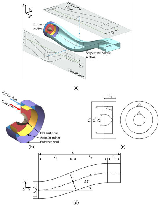
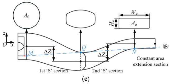
Figure 1.
Geometric model of the serpentine exhaust system with a spanwise offset. (a) Geometry of the serpentine exhaust system. (b) Geometry of the entrance section. (c) Parameters of the entrance section. (d) Projection of serpentine nozzle section (horizontal plane). (e) Projection of serpentine nozzle section (vertical plane). The blue line in (e) represents the condition of fully shielding high-temperature components.

Table 1.
Key geometric parameters of the serpentine exhaust system.
In Equations (1) and (2), L represents the nozzle axial length, and x is the streamwise location. A0 denotes the inlet area, Ae the exit area, and A the cross-sectional area at position x. ΔS represents the offset of the serpentine nozzles, and s corresponds to the offset at the x coordinate. The distributions of area and centerline governed by these equations exhibit varying rates of change. Equations #A1 and #L1 describe rapid change at the exit, #A2 and #L2 represent modest change, and #A3 and #L3 provide rapid change at the entrance. Figure 2 illustrates the trends for these cases.
Figure 2.
Different distributions of area and centerline.
The Distribution of Centerline (DC), including the Distribution of Centerline for the first ‘S’ section in the Vertical direction (DCV1), the Distribution of Centerline for the second ‘S’ section in the Vertical direction (DCV2), and the Distribution of Centerline in the Spanwise direction (DCS), each have three types of change rate, resulting in 81 models if a full-factorial experiment is conducted. Reference [25] used a Taguchi-based optimization method to determine the selection principles for the distribution of the ‘Preferred Nozzle’, ‘Modest Nozzle’, and ‘Undesirable Nozzle’, as shown in Table 2. The structural characteristics of each nozzle are shown in Figure 3. When the axial length L = 4.8D0, the vertical offset ΔZ = 0.1D0, and the spanwise offset ΔY = 1.0D0, the ‘Preferred nozzle’ shows a larger cross-section area, with a weaker overall acceleration effect of the gas flow and lower overall shear stress on the wall surface. At the same time, its centerline reduces the curvature near the constant-area extension section, with less pronounced localized acceleration of the gas flow and smaller local and friction losses. Therefore, compared to the ‘Modest Nozzle’ and ‘Undesirable Nozzle’, the ‘Preferred Nozzle’ exhibits superior aerodynamic performance at this offset configuration.
Table 2.
Comparisons of distribution of the ‘Preferred Nozzle’, ‘Modest Nozzle’, and ‘Undesirable Nozzle’ (L = 4.8D0, ΔZ = 0.1D0, ΔY = 1.0D0).
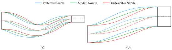
Figure 3.
Comparisons of structures of the ‘Preferred Nozzle’, ‘Modest Nozzle’, and ‘Undesirable Nozzle’ (L = 4.8D0, ΔZ = 0.1D0, ΔY = 1.0D0). (a) Projection on the vertical plane. (b) Projection on the horizontal plane. The dashed lines of different colors represent the centerline of the corresponding nozzles.
2.2. Numerical Method
The numerical grid of the computational domain is shown in Figure 4. Downstream of the nozzle exit, there is an external flow domain with a diameter of 6D0 and a length of 15D0 (see Figure 4a), allowing the exhaust gas to fully develop [29]. A fully structured hexahedral grid is generated using a three-layer O-block strategy in ANSYS ICEM 14.0 [23]. These layers correspond to the entrance and nozzle wall, the mixer wall, and the cone wall. Boundary layers are also applied to achieve y + ≈ 1, as shown in Figure 4b.
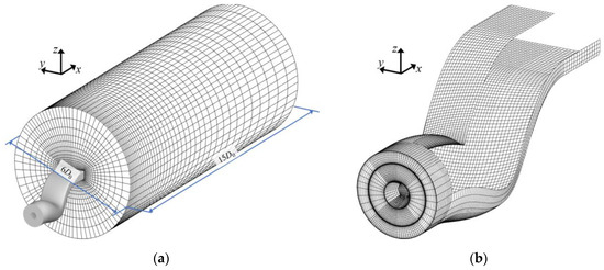
Figure 4.
Numerical grid of the computational domain. (a) Computational domain. (b) Grids of the serpentine exhaust system.
As shown in Equations (3)–(7), the equations solved are the fully 3D, steady, compressible, Reynolds-averaged Navier–Stokes equations [19]. The governing equations include the mass conservation, momentum conservation, and energy conservation equations [7]. Due to the significant differences in the composition of core gas flow compared to air, as well as its high temperature, both the species transport and the Discrete Ordinate (DO) radiation models are also activated to account for species concentration and radiative heat transfer effects [30].
where ρ is the density of gas, is the velocity vector, P is static pressure, is stress tensor, E is total energy, λeff is effective conductivity, and T is temperature. hj, , and Yj represent the enthalpy, diffusion flux, and local mass fraction for species j, respectively. is the position vector, is the direction vector, kα is the absorption coefficient, σ is the Stefan–Boltzmann constant, and L is radiance.
In References [18,19], six turbulence models were used to carry out the numerical calculations for the serpentine nozzles, and comparisons with experimental results indicate that the Shear-Stress Transport (SST κ-ω) turbulence model best captures the flow field details for serpentine nozzles. In addition, the flow and heat transfer control equations are discretized using a second-order upwind scheme [19]. The specified convergence criteria for the numerical solutions required the residuals of the energy equation to be less than 10−6 and the residuals of the other equations to be less than 10−4. The parallel calculations are performed on a 4.20 GHz Intel-Core (i7-7700 K) CPU with 32 GB memory. The computation time for each simulation run is approximately 38 h. As shown in Figure 5a, numerical calculations were performed based on the experimental model from Reference [19]. Results show that the calculated static pressure distribution along the upper and lower walls of the nozzle is in good agreement with the experimental results, with a maximum error of 4.67%, demonstrating the accuracy of the CFD method used in this study. As shown in Figure 5b, the results of the grid independence study based on the nozzle exit Ma and static pressure indicate that a mesh with 4.177 million cells is optimal.
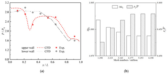
Figure 5.
Verification of numerical method and grid independence. (a) Numerical method verification [19]. (b) Grid independence verification.
As shown in Table 3, both the core flow and bypass flow inlets of the serpentine exhaust system are modeled with pressure inlet boundaries, specifying flow pressure, temperature, and composition. Serpentine converging nozzles are typically used in flying-wing aircraft, which generally operate at high subsonic cruise speeds. Therefore, a pressure far-field boundary condition with a Mach number (Ma) of 0.8 is applied to the inlet and cylindrical surfaces of the external domain, while the pressure outlet boundary is used for its outlet surface, applying high-altitude 11 km airflow parameters. The emissivity of all solid wall surfaces is set to 0.8. Due to the temperature differences between the inner and outer sides of the fluid, the annular mixer wall needs to be set as a coupled heat transfer surface to account for the heat exchange between them. The exhaust system has a limited length, and the high gas flow velocity results in very limited heat exchange with the external environment. Therefore, the external wall of the entrance and nozzle are modeled with adiabatic, no-slip conditions.
Table 3.
Boundary condition settings.
2.3. Evaluation Index
The axial thrust coefficient (Cf) is defined as the ratio of actual thrust to ideal thrust (one-dimensional isentropic fully expanded flow thrust) [31].
where F is the actual thrust, which is determined by parameters such as the nozzle exit area (Ae), mass flow rate (m), flow density (ρ), axial velocity (U), pressure (Pe), and ambient pressure (Pamb). Fi is the ideal thrust, and for a double-flow convergent nozzle, it can be calculated based on the conditions of static pressure balance and the assumption that the core flow and bypass flow slides and expands separately [32].
The losses inside serpentine nozzles include local and friction losses. The local loss comes from local acceleration, secondary flow, and shock loss and can be visually analyzed through the flow parameter (e.g., Ma) distributions inside the nozzle. The local loss coefficient Ll (Equation (10)) can reflect its magnitude. Friction loss relates to the velocity gradient near the wall and the wetted area and is quantified using the friction loss coefficient Lf (Equation (11)) [32].
where Ff is the friction force on the inner wall of serpentine nozzles.
3. Results and Discussion
3.1. Influence of ΔZ (ΔY = 0)
With a fixed spanwise offset of ΔY = 0, the study investigates the effect of different vertical offsets (ΔZ = −0.50D0, −0.25D0, 0.10D0, 0.50D0, 1.00D0) on the aerodynamics of serpentine nozzles. Figure 6 shows the projections of the ‘Preferred Nozzle’ and ‘Modest Nozzle’ structures on the vertical and horizontal planes, with the solid line representing the ‘Preferred Nozzle’ and the corresponding dashed lines indicating the ‘Modest Nozzle’. For simplicity, the upper and lower parts of the vertical projection are defined as the upper and lower walls, respectively, while the upper and lower parts of the horizontal projection are defined as the right and left walls, respectively, based on the rear perspective of the nozzle. As shown in Figure 6, there are significant differences in the vertical projection under different vertical offsets. In the first ‘S’ section, the difference between the two gradually decreases as the vertical offset changes from −0.50D0 to 1.00D0. When ΔZ = −0.50D0, the ‘Preferred Nozzle’, in which the distribution of the centerline changes rapidly at the entrance, results in a very large curvature of the lower wall at the inlet. Conversely, the ‘Modest Nozzle’, in which the distribution of the centerline changes modestly, allows for a smooth transition of the lower wall at the nozzle inlet with the entrance wall. In the second ‘S’ section, the difference between the two gradually increases as the vertical offset changes from −0.50D0 to 1.00D0. When ΔZ = 1.00D0, the ‘Preferred Nozzle’ effectively reduces the curvature of the lower wall profile at the exit of the second ‘S’ section. Conversely, the ‘Modest Nozzle’ leads to a significantly larger curvature at the same position, inevitably increasing the flow acceleration losses and wall friction losses in the surrounding region. Under different vertical offsets, the projections of the ‘Preferred Nozzle’ and ‘Modest Nozzle’ on the horizontal plane almost overlap. The ‘Preferred Nozzle’, characterized by an area distribution with rapid change at the exit, has a larger cross-sectional area along the length of the nozzle, apart from the inlet and exit, compared to the ‘Modest Nozzle’, which exhibits a modest area change rate. Therefore, the envelope region of its left and right wall profiles is also larger, with the biggest difference between the two appearing at the exit of the first ‘S’ section.
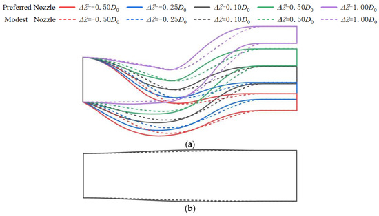
Figure 6.
Structures of serpentine nozzles with different ΔZ (ΔY = 0). (a) Projection on vertical plane; (b) projection on horizontal plane.
The complex serpentine structure of the nozzle subjects the gas flow to centrifugal and centripetal forces, which cause Ma at each cross-section to exhibit obviously asymmetric characteristics. When the pressure near the wall is low, the gas flow experiences centrifugal force, leading to higher speed and local acceleration. In contrast, centripetal force causes local flow deceleration. To clarify the flow characteristics inside the nozzle, six sections are established with positions of x/(L1 + L2) =0, 0.2, 0.4, 0.6, 0.8, 1.0, as shown in Figure 7. I0 and I5 represent the inlet to the first ‘S’ section and the exit of the second ‘S’ section, respectively. I1 and I2 are located in the first ‘S’ section, while I3 and I4 are located in the second. The symmetry plane refers to the symmetry plane of the constant-area extension section.
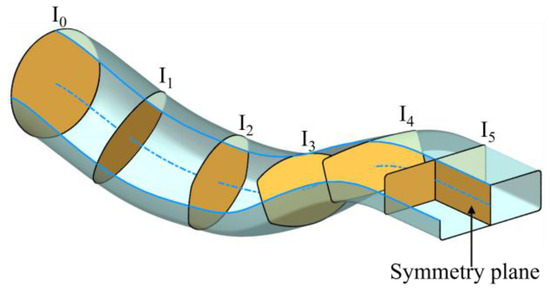
Figure 7.
Locations of typical sections. The blue surface represents the nozzle wall, and the orange planes represent the typical sections.
The Ma distribution of the ‘Preferred Nozzle’ characteristic sections under different vertical offsets is shown in Figure 8. Due to the slightly higher total pressure of the bypass flow compared to the core flow, the corresponding velocity of the former is also higher than that of the latter. The interface between these two can be clearly identified in the first ‘S’ section. As the flow enters the second ‘S’ section, the velocities of these two tend to be consistent. The area of the nozzle channel gradually decreases, causing the flow velocity to increase progressively. Although the area within the constant-area extension section remains unchanged, the curvature of the lower wall profile at the exit of the second ‘S’ section causes the flow tube to still exhibit a contracting state, leading to the continued acceleration of the gas flow, which approaches sonic speed near the nozzle exit. When ΔZ = −0.50D0, a local low-Ma flow develops at the lower wall of the first ‘S’ section entrance due to the constraint of complete shielding propagating downstream. A distinct recirculation zone appears within this section and gradually dissipates after Section I3. When ΔZ ≥ −0.25D0, the flow smooths out, with no recirculation zones, though differences in acceleration characteristics remain between nozzles. Specifically, as ΔZ increases from −0.25D0 to 1.00D0, the curvature of the lower wall at the nozzle entrance decreases due to the reduction in ΔZ1. This leads to a gradual reduction in the high-Ma region below Section I0. The differences in Ma distribution at Sections I1 and I2 among different models are minimal, with the most uniform distribution occurring at ΔZ = 1.00D0, where ΔZ1 is nearly zero, and there is little curvature in the wall profiles. As vertical offsets increase, the curvature of the upper wall at the exit of the first ‘S’ section grows, expanding the high-Ma region above Section I3. The curvature of the lower wall near the second ‘S’ section exit becomes more influential at Section I4, shifting the high-Ma region to the lower flow channel, with both its range and magnitude increasing as the vertical offset increases. The Ma distribution in Section I5 tends toward uniformity. In the constant-area extension section, the gas flow reaches supersonic speeds near the nozzle exit under all vertical offsets, with no local supersonic regions. In summary, within the first ‘S’ section, the ‘Preferred Nozzle’ with negative vertical offsets exhibits a more pronounced asymmetry in the Ma distribution due to its greater ΔZ1. Conversely, in the second ‘S’ section, the ‘Preferred Nozzle’ with larger positive vertical offsets demonstrates a more significant acceleration effect corresponding to the increased wall curvature. However, in the constant-area extension section, the Ma distribution shows little difference across the different vertical offsets.

Figure 8.
Comparisons of section Ma contours of nozzles with different ΔZ (ΔY = 0, Preferred Nozzle).
The Ma distribution of the ‘Modest Nozzle’ characteristic sections under different vertical offsets is shown in Figure 9. In the first ‘S’ section, similar to the ‘Preferred Nozzles’, the asymmetric characteristic of the Ma distribution in the ‘Modest Nozzle’ weakens as ΔZ increases. When ΔZ = 1.00D0, its circumferential distribution is the most uniform. When ΔZ = −0.50D0, in contrast to the ‘Preferred Nozzle’, the recirculation zone near the lower wall of the first ‘S’ section disappears, effectively avoiding secondary flow losses. In the second ‘S’ section, the ‘Modest Nozzle’ has a more gradual centerline change, resulting in larger curvature at both the upper wall at the entrance and the lower wall at the exit of the second ‘S’ section, compared to the ‘Preferred Nozzle’. This causes stronger local gas flow acceleration, particularly in the upper region of Section I3 and the lower region of Section I5. In Section I3, a high-speed flow region with Ma > 0.6 begins to appear when ΔZ = 0.10D0, and as ΔZ further increases, the range and size of this region gradually increase. At section I5, a localized supersonic zone emerges when ΔZ = 0.10D0, and when ΔZ ≥ 0.50D0, this supersonic region occupies more than half of the flow channel, inevitably resulting in significant local losses. In the constant-area extension section, the Ma distribution differs noticeably. When ΔZ = −0.50D0, the flow velocity is relatively uniform. When −0.25D0 ≤ ΔZ ≤ 0.10D0, localized supersonic regions begin to appear on the lower wall upstream of this section, although their range is limited. However, as ΔZ increases beyond 0.50D0, a rightward sloping expansion waveforms, occupying the entire flow channel and reflecting off the upper and lower walls. This complex wave structure leads to significant flow losses.
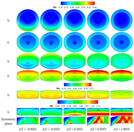
Figure 9.
Comparisons of section Ma contours of nozzles with different ΔZ (ΔY = 0, Modest Nozzle).
The wall shear stress distribution of the ‘Preferred Nozzle’ walls under different vertical offsets is shown in Figure 10. The shear stress on a solid wall is related to the velocity gradient of the nearby gas flow, with higher velocity gradients leading to higher shear stress. In a serpentine convergent nozzle, the gas flow continuously accelerates, causing the wall shear stress to increase from the nozzle entrance to the exit. The distribution of shear stress is complex due to varying acceleration effects in different regions of the nozzle. Corresponding to the high-speed flow region near the inner wall of the serpentine channel, the shear stress is higher on the lower wall at the first ‘S’ section entrance, the upper wall at the second ‘S’ section entrance, and the lower wall at the second ‘S’ section exit. When ΔZ = −0.50D0, a low shear stress band forms at the lower wall near the nozzle entrance and gradually extends downstream, remaining noticeable up to the second ‘S’ section, where its width decreases. There is also a low shear stress region at the middle of the lower wall in the constant-area extension section, flanked by high shear stress bands extending to the nozzle exit. These characteristics indicate that the recirculation zone significantly influences the shear stress distribution along the entire lower wall. When ΔZ ≥ −0.25D0, the shear stress distribution pattern becomes more pronounced. As ΔZ increases, the high-Ma region at the lower part of Section I0 shrinks, and the high shear stress region at the lower wall of the first ‘S’ section entrance diminishes, disappearing when ΔZ = 1.00D0. In contrast, the high-Ma regions at the upper part of Section I3 and lower part of Section I5 increase, while high shear stress regions at the upper wall of the second ‘S’ section entrance and the lower wall of its exit expand. The shear stress distribution in other areas shows minimal change.
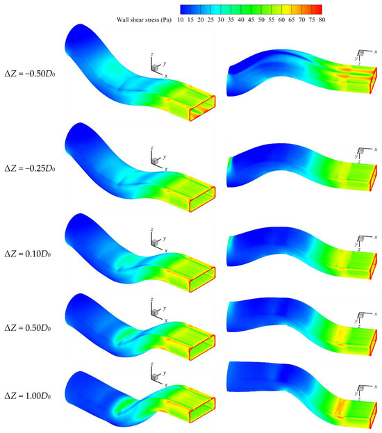
Figure 10.
Comparisons of wall shear stress of nozzles with different ΔZ (ΔY = 0, Preferred Nozzle).
The wall shear stress distribution of the ‘Modest Nozzle’ walls under different vertical offsets is shown in Figure 11. The ‘Modest Nozzle’ has a slightly higher gas flow velocity than the ‘Preferred Nozzle’, resulting in slightly higher wall shear stress values. This difference is most noticeable in the upper wall of the second ‘S’ section. When ΔZ = −0.50D0, there is no recirculation zone present in the ‘Modest Nozzle’, so its shear stress distribution is essentially the same as those of ‘Modest Nozzles’ and ‘Preferred Nozzles’ with ΔZ ≥ −0.25D0. High shear stress regions occur at the lower wall of the first ‘S’ section entrance, the upper wall of the second ‘S’ section entrance, and the lower wall of the second ‘S’ section exit. When ΔZ ≥ 0.50D0, the high shear stress region at the lower wall of the second ‘S’ section exit extends to the upper wall of the constant-area extension section and continues downstream, forming an ‘N’-shaped distribution on the sidewalls, reflecting the expansion waves in this section.
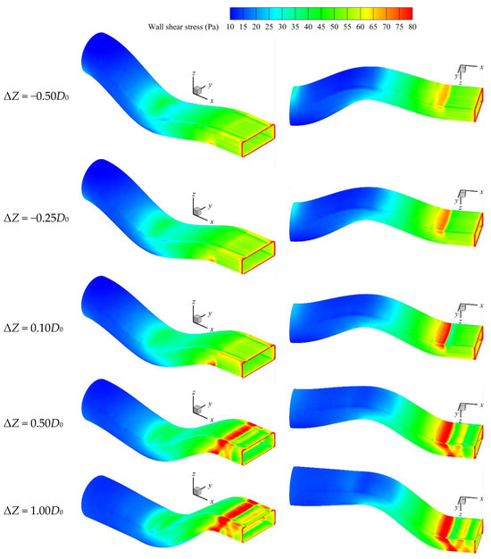
Figure 11.
Comparisons of wall shear stress of nozzles with different ΔZ (ΔY = 0, Modest Nozzle).
The comparisons of loss coefficient and axial thrust coefficient with different vertical offsets are shown in Figure 12. For the ‘Preferred Nozzle’, when ΔZ = −0.50D0, both the local and friction loss coefficients reach their maximum values, with an axial thrust coefficient of approximately 0.960, indicating relatively poor aerodynamic performance. Conversely, when ΔZ ≥ −0.25D0, as the vertical offset increases, both loss coefficients gradually increase, though the increase is minimal. Consequently, the axial thrust coefficient remains consistently around 0.973, demonstrating superior aerodynamic performance. For the ‘Modest Nozzle’, although the local and friction loss coefficients are lowest at ΔZ = −0.50D0 with an axial thrust coefficient above 0.971, the local loss coefficient increases sharply with higher vertical offsets, causing a rapid drop in the axial thrust coefficient. This trend becomes more significant while changes in the friction loss coefficient are negligible. In comparison, the ‘Preferred Nozzle’ exhibits better aerodynamic performance when ΔZ ≥ −0.25D0.
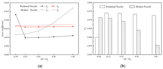
Figure 12.
Comparisons of aerodynamic performance of nozzles with different ΔZ (ΔY = 0). (a) Comparisons of loss coefficient. (b) Comparisons of axial thrust coefficient.
3.2. Influence of ΔY (ΔZ = −0.50D0)
With a fixed vertical offset of ΔZ = −0.50D0, the study investigates the effect of different spanwise offsets (ΔY = 0, 0.5D0, 1.0D0, 1.5D0, 2.0D0) on the aerodynamics of serpentine nozzles. Figure 13 shows the projections of the ‘Preferred Nozzle’ and ‘Modest Nozzle’ structures on the vertical and horizontal planes. The maximum difference on the vertical plane occurs in the middle of the first ‘S’ section, with the ‘Modest Nozzle’ consistently showing a smaller vertical offset throughout the entire section. The differences between the two are relatively minor in the second ‘S’ section. However, there is a significant disparity in the horizontal plane projections at different spanwise offsets, with the maximum difference observed at the exit of the first ‘S’ section. With the increase in the spanwise offset, the difference between the left and right wall profiles of the ‘Preferred Nozzle’ and ‘Modest Nozzle’ becomes increasingly significant. When ΔY = 2.0D0, at the entrance of the first ‘S’ section, the left and right wall profiles of the ‘Modest Nozzle’ have a smaller curvature, while at the exit of the second ‘S’ section, the curvature of the ‘Preferred Nozzle’ profiles is smaller.
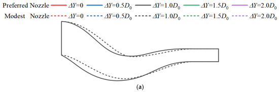
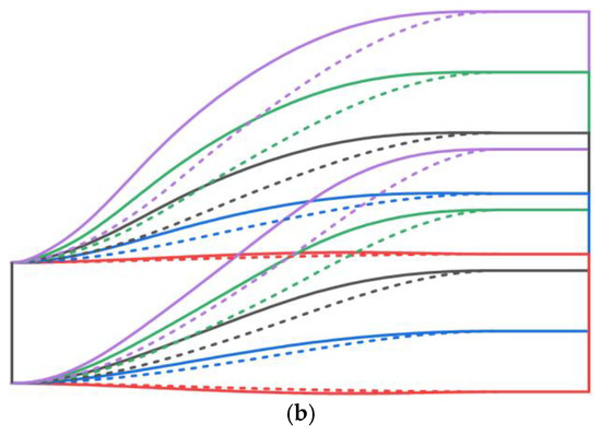
Figure 13.
Structures of serpentine nozzles with different ΔY (ΔZ = −0.50D0). (a) Projection on vertical plane. (b) Projection on horizontal plane.
The Ma distribution of the ‘Preferred Nozzle’ characteristic sections under different spanwise offsets is shown in Figure 14. The high-curvature lower wall at the entrance of the first ‘S’ section accelerates the gas flow, creating a high-speed region in Section I0. As the spanwise offset increases, this region shifts to the lower right due to the combined effects of the high-curvature right wall at the section’s entrance. The localized low-Ma recirculation zone near the lower wall at the entrance becomes a prominent feature of the first ‘S’ section, and it shifts rightward in Sections I1 and I2 as the spanwise offset increases. Upon entering the second ‘S’ section, this recirculation zone compresses and fades due to the inward geometry of the lower and right walls. Meanwhile, the curvature of the left and upper walls in the second ‘S’ section entrance accelerates the gas flow, creating a high-Ma region in the upper left of Section I3. At the exit of the second ‘S’ section, the curvature of the left and lower walls generates another high-Ma region in the lower left of Sections I4 and I5, which becomes more pronounced at larger spanwise offsets. In the constant-area extension section of the ‘Preferred Nozzle’, despite variations in Ma across different spanwise offsets, the gas flow only remains supersonic near the exit, resulting in relatively low local losses.
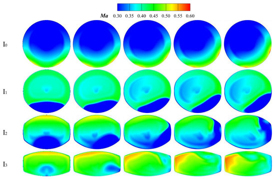
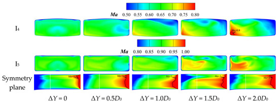
Figure 14.
Comparisons of section Ma contours of nozzles with different ΔY (ΔZ = −0.50D0, Preferred Nozzle).
The Ma distribution of the ‘Modest Nozzle’ characteristic sections under different spanwise offsets is shown in Figure 15. As the spanwise offset increases, high-Ma regions of Sections I0 and I1 in the first ‘S’ section shift gradually from the lower part towards the lower right, while the high-Ma region of Section I2 moves from the upper part towards the upper right. Overall, the Ma distribution in these sections becomes more uniform compared to the ‘Preferred Nozzle’. In the second ‘S’ section, when ΔY = 0, Section I3 shows a significant acceleration, but its velocity becomes more uniform as it progresses to Sections I4 and I5. When ΔY ≥ 0.5D0, a local high-Ma region remains at Section I3, shifting towards the upper left. The high-curvature wall on the left of Section I4 causes a distinct high-Ma region, with both its range and magnitude increasing significantly as the spanwise offset grows. As the high-Ma region develops, the gas flow can reach supersonic speeds at the exit of the second ‘S’ section, particularly at larger offsets (ΔY ≥ 1.0D0), where supersonic flow occupies nearly half of the flow channel at Section I5. The high-Ma flow in the constant-area extension section will inevitably cause significant flow losses.
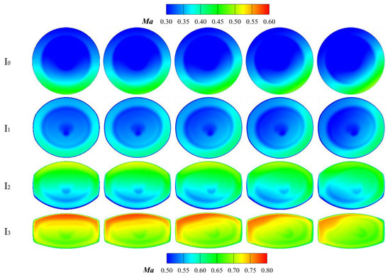
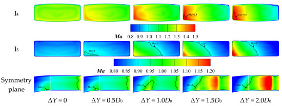
Figure 15.
Comparisons of section Ma contours of nozzles with different ΔY (ΔZ = −0.50D0, Modest Nozzle).
Since the friction loss coefficient changes little with different spanwise offsets, and the difference between the ‘Preferred Nozzle’ and ‘Modest Nozzle’ is also minimal, the comparisons of wall shear stress will no longer be analyzed in the following text. The comparisons of loss coefficient and thrust coefficient with different spanwise offsets are shown in Figure 16. The local and friction loss coefficients of both models increase with the spanwise offset. The friction loss coefficient of the ‘Preferred Nozzle’ is slightly lower than that of the ‘Modest Nozzle’, though both show minimal variation. The local loss coefficient of the ‘Preferred Nozzle’ remains consistently higher than the friction loss coefficient but with less variation than the ‘Modest Nozzle’, and the thrust coefficient reduction at larger spanwise offsets stays within 0.7%. At smaller offsets (ΔY ≤ 1.0D0), the local loss coefficient of the ‘Modest Nozzle’ is lower than the friction loss coefficient. However, at larger offsets (ΔY > 1.0D0), the local loss coefficient increases sharply, causing a significant drop in axial thrust. Notably, at ΔY = 2.0D0, the axial thrust coefficient of the ‘Modest Nozzle’ is lower than that of the ‘Preferred Nozzle’, which has a large internal recirculation zone.
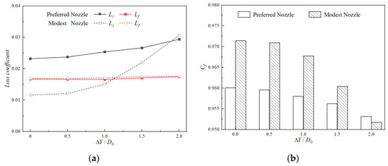
Figure 16.
Comparisons of aerodynamic performance of nozzles with different ΔY (ΔZ = −0.50D0). (a) Comparisons of loss coefficient. (b) Comparisons of axial thrust coefficient.
3.3. Influence of ΔY (ΔZ = 0.10D0)
With a fixed vertical offset of ΔZ = 0.10D0, the study investigates the effect of different spanwise offsets (ΔY = 0, 0.5D0, 1.0D0, 1.5D0, 2.0D0) on the aerodynamics of serpentine nozzles. Figure 17 shows the projections of the ‘Preferred Nozzle’ and ‘Modest Nozzle’ structures on the vertical and horizontal planes. At different spanwise offsets, the differences in the upper and lower wall profiles of both nozzles are largest at the midpoints of the first and second ‘S’ sections, with these differences being roughly equal between the two sections. The ‘Modest Nozzle’ has a larger curvature on the lower wall at the exit of the second ‘S’ section. The projection of the above models on the horizontal plane is consistent with Section 3.2, so no further explanation is needed.
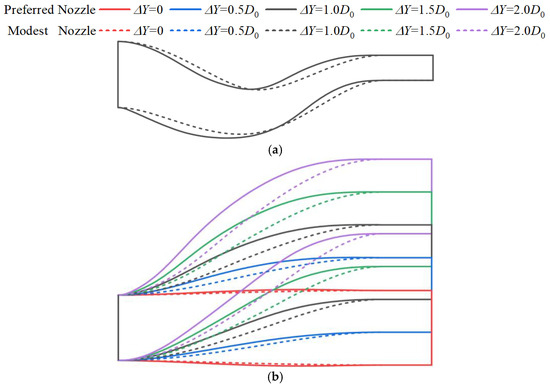
Figure 17.
Structures of serpentine nozzles with different ΔY (ΔZ = 0.10D0). (a) Projection on vertical plane. (b) Projection on horizontal plane.
The Ma distributions of the ‘Preferred Nozzle’ and ‘Modest Nozzle’ characteristic sections under different spanwise offsets are shown in Figure 18 and Figure 19, respectively. In the first ‘S’ section, the high-Ma region at Section I0 of the ‘Preferred Nozzle’ has both a larger range and higher values than that of the ‘Modest Nozzle’. As the spanwise offset increases, these differences become more pronounced, reflecting the varying curvatures of the lower and right walls at the section entrance. In Sections I2 and I3, the ‘Modest Nozzle’ shows significantly higher average Ma values, especially in Section I4, where its Ma distribution is more uniform. This is mainly due to the modest area change rate, which keeps the cross-sectional area consistently smaller than that of the ‘Preferred Nozzle’, leading to a stronger acceleration of the gas flow. In the second ‘S’ section, the curvature of the upper wall at the inlet and lower wall at the exit creates local high-Ma regions in Sections I3 and I4 for both nozzles. As the spanwise offset increases, the high-Ma region shifts left due to the combined effect of the left wall curvature. However, the acceleration in the ‘Preferred Nozzle’ is significantly less than in the ‘Modest Nozzle’. As the gas flow enters the constant-area extension section, the Ma distribution differs significantly between the two nozzle configurations. In the ‘Preferred Nozzle’, the Ma distribution at Section I5 is more uniform, with minimal variation across spanwise offsets. The gas flow reaches sonic speed only at the nozzle exit, resulting in low flow losses. In contrast, the ‘Modest Nozzle’ shows a strong acceleration effect due to the high curvature of the lower wall at the section entrance. At Section I5, the supersonic region nearly occupies half of the flow channel and shifts left as the spanwise offset increases, with Ma exceeding 1.5 in the lower left of Section I5. For smaller spanwise offsets (ΔY = 0, 0.5D0), the ‘Modest Nozzle’ has two distinct supersonic regions: one caused by the high-curvature lower wall at the inlet and another from normal flow acceleration within the section. For larger spanwise offsets (ΔY ≥ 1.0D0), these regions merge, creating shock waves that result in significant flow losses.
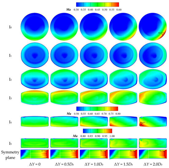
Figure 18.
Comparisons of section Ma contours of nozzles with different ΔY (ΔZ = 0.10D0, Preferred Nozzle).

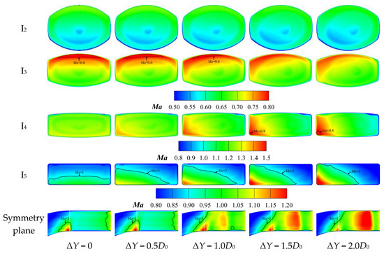
Figure 19.
Comparisons of section Ma contours of nozzles with different ΔY (ΔZ = 0.10D0, Modest Nozzle).
The comparisons of loss coefficient and thrust coefficient with different spanwise offsets are shown in Figure 20. Compared to the ‘Preferred Nozzle’ with ΔZ = −0.50D0, the local loss coefficient of the ‘Preferred Nozzle’ with ΔZ = 0.10D0 is consistently lower than the friction loss coefficient and less sensitive to spanwise offsets. As a result, the axial thrust coefficient stays above 0.972 across different offsets, with a maximum variation within 0.17%. In contrast, the local loss coefficient of the ‘Modest Nozzle’ shows significant variation, with a sharp drop in the axial thrust coefficient at larger spanwise offsets, highlighting its poorer aerodynamic performance compared to the ‘Preferred Nozzle’.
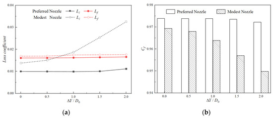
Figure 20.
Comparisons of aerodynamic performance of nozzles with different ΔY (ΔZ = 0.10D0). (a) Comparisons of loss coefficient. (b) Comparisons of axial thrust coefficient.
3.4. Influence of ΔY (ΔZ = 1.00D0)
With a fixed vertical offset of ΔZ = 1.00D0, the study investigates the effect of different spanwise offsets (ΔY = 0, 0.5D0, 1.0D0, 1.5D0, 2.0D0) on the aerodynamics of serpentine nozzles. Figure 21 shows the projections of the ‘Preferred Nozzle’ and ‘Modest Nozzle’ structures on the vertical and horizontal planes. Under different spanwise offsets, the upper and lower wall profiles of the first ‘S’ section for both the ‘Preferred Nozzle’ and ‘Modest Nozzle’ are largely consistent, with the flow channel remaining nearly horizontal. This is due to the minimal vertical offset required in this section to meet the shielding constraint at ΔZ = 1.00D0. However, in the second ‘S’ section, the large vertical offset (ΔZ2) creates a noticeable difference between the two nozzles, significantly impacting the transition from the lower wall at the section exit to the constant-area extension section. The projection of these models on the horizontal plane also aligns with the nozzle at ΔZ = −0.50D0, which is not discussed further here.
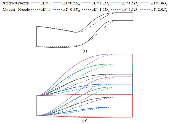
Figure 21.
Structures of serpentine nozzles with different ΔY (ΔZ = 1.00D0). (a) Projection on vertical plane; (b) Projection on horizontal plane.
The Ma distributions of the ‘Preferred Nozzle’ and ‘Modest Nozzle’ characteristic sections under different spanwise offsets are shown in Figure 22 and Figure 23, respectively. The Ma distribution in Sections I0, I1, and I2 of both nozzles is nearly symmetrical in the vertical direction. However, due to the curvature of the left and right walls, the high-Ma regions shift to the right or left sides in each section for the serpentine nozzle with a spanwise offset (ΔY > 0). Compared to the ‘Preferred Nozzle’ with ΔZ = 0.10D0, the Ma distribution of the ‘Preferred Nozzle’ with ΔZ = 1.00D0 is nearly identical in Sections I3, I4, I5, and the symmetry plane of the constant-area extension section. Compared to the ‘Modest Nozzle’ with ΔZ = 0.10D0, the Ma distribution of the ‘Modest Nozzle’ with ΔZ = 1.00D0 is similar in Sections I3, I4, and I5. However, the larger vertical offset of the second ‘S’ section causes a more extensive and higher high-Ma region at Section I5 for the ΔZ = 1.00D0 nozzle. In the constant-area extension section, the supersonic flow nearly fills the entire channel, and its wave structure becomes more complex. Notably, when the spanwise offset is small (ΔY = 0, 0.5D0), the two small supersonic regions disappear, replaced by a right-leaning expansion wave that continuously reflects within the constant-area extension section. This causes significant local losses, leading to a notable decline in aerodynamic performance.
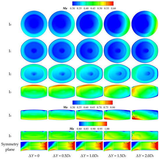
Figure 22.
Comparisons of section Ma contours of nozzles with different ΔY (ΔZ = 1.00D0, Preferred Nozzle).
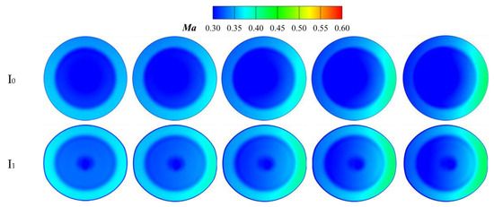
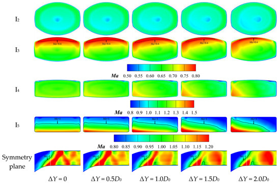
Figure 23.
Comparisons of section Ma contours of nozzles with different ΔY (ΔZ = 1.00D0, Modest Nozzle).
The comparisons of loss coefficient and thrust coefficient with different spanwise offsets are shown in Figure 24. Similar to the case with ΔZ = 0.10D0, the local loss and friction loss coefficients of the ‘Preferred Nozzle’ show minimal variation. The thrust coefficient remains consistently above 0.970 across different spanwise offsets, with a maximum difference of only 0.17%. For the ‘Modest Nozzle’, the friction loss coefficient also shows little variation, but the local loss coefficient increases significantly and exceeds that of the ΔZ = 0.10D0 nozzle at the same spanwise offset. As a result, the axial thrust coefficient declines further, leading to a deterioration in aerodynamic performance.
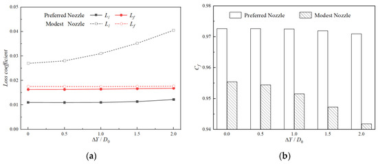
Figure 24.
Comparisons of aerodynamic performance of nozzles with different ΔY (ΔZ = 1.00D0). (a) Comparisons of loss coefficient. (b) Comparisons of axial thrust coefficient.
Several ‘Preferred Nozzle’ designs have been tested across a range of vertical offsets (−0.50D0 ≤ ΔZ ≤ 1.50D0) and spanwise offsets (0 ≤ ΔY ≤ 2.0D0), with their axial thrust coefficients calculated numerically, as shown in Figure 25. The impact of vertical offset is significantly greater than that of spanwise offset. Except for the nozzle with ΔZ = −0.50D0, which performs poorly due to a large internal recirculation region, the nozzle in which the area changes rapidly at the exit and centerline changes rapidly at the entrance can achieve excellent aerodynamic performance across a wide range of offsets, making it adaptable to the internal space constraints of various flying wing layouts. More specifically, based on these results, recommendations for the serpentine nozzle design process can be made. The fundamental principle is to avoid the formation of recirculation zones induced by the lower wall surface at the first ‘S’ section inlet and the presence of complex supersonic regions within the constant-area extension section. When −0.25D0 ≤ ΔZ < 0.10D0, the axial thrust coefficient of the nozzle remains above 0.97 with smaller spanwise offsets (ΔY ≤ 1.0D0), but it rapidly decreases with larger spanwise offsets (ΔY > 1.0D0). Therefore, when designing the serpentine nozzle for this range of vertical offsets, larger spanwise offsets should be avoided. When ΔZ ≥ 0.10D0, the local losses and friction losses under different spanwise offsets remain essentially unchanged, and the axial thrust coefficient stays above 0.97. Thus, for the serpentine nozzle design in this range of vertical offsets, the spanwise offset can be adjusted appropriately to meet the internal space requirements for other equipment and components without significantly affecting the engine’s thrust performance.
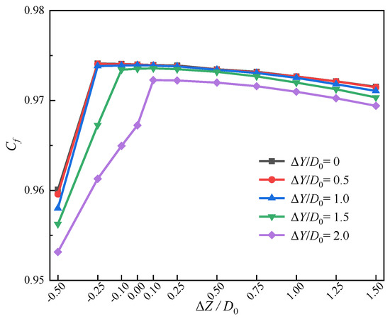
Figure 25.
Axial thrust coefficient distribution.
4. Conclusions
A series of ‘Preferred Nozzles’ and ‘Modest Nozzles’ are created to explore the effects of different vertical and spanwise offsets on the aerodynamic performance of serpentine nozzles. The comparative analysis of two sets of nozzles further clarified the mechanism by which the area/centerline variation rate affects the internal flow field characteristics. The main conclusions are as follows:
- (1)
- For the ‘Preferred Nozzle’, the vertical offset (ΔZ) has a significant impact on its aerodynamic performance. When ΔZ = −0.50D0, the recirculation zone induced by the high-curvature lower wall at the first ‘S’ section entrance becomes the most critical flow feature, leading to a consistently high local loss coefficient and an axial thrust coefficient below 0.96. However, when ΔZ ≥ 0.10D0, aside from the local high-Ma regions and high shear stress areas near the upper wall at the exit of the first ‘S’ section and the lower wall at the exit of the second ‘S’ section, the flow velocity and wall shear stress distribution inside the nozzle transition more uniformly, with the axial thrust coefficient remaining above 0.97.
- (2)
- For the ‘Preferred Nozzle’, the spanwise offset (ΔY) has little effect on its aerodynamic performance. Particularly when ΔZ ≥ 0.10D0, the local losses and friction losses remain nearly unchanged across different ΔY, with the axial thrust coefficient staying above 0.97, and the maximum difference being only around 0.17%. Therefore, when designing the serpentine exhaust system buried within the flying wing layout, the spanwise offset of the nozzle can be adjusted within an appropriate vertical offset to accommodate the internal space requirements for other equipment and components in the fuselage without significantly affecting the engine’s thrust performance.
- (3)
- For the ‘Modest Nozzle’, when ΔY = 0 and ΔZ ≤ 0.10D0, there are localized high-Ma regions near the upper wall at the exit of the first ‘S’ section and the lower wall at the exit of the second ‘S’ section. The local loss coefficient remains low, staying below the friction loss coefficient, while the nozzle’s thrust coefficient remains around 0.97. However, when ΔY = 0 and ΔZ ≥ 0.50D0, complex wave structures formed by the continuous reflection of expansion waves in the constant-area extension section lead to significant flow losses. This causes a sharp increase in the local loss coefficient, which exceeds the friction loss coefficient, resulting in a rapid decline in the nozzle’s thrust coefficient.
- (4)
- For the ‘Modest Nozzle’, the spanwise offset has a significant impact on its performance. The variation in the spanwise centerline rate results in increased curvature on the left wall at the exit of the second ‘S’ section, which induces localized high-Ma flow and generates complex wave structures within the constant-area extension section. This leads to a rapid increase in local flow losses. Additionally, a complex high shear stress distribution will be observed on the wall of the constant-area extension section, though it has minimal impact on the friction loss coefficient. The axial thrust coefficient decreases rapidly.
- (5)
- When designing a serpentine nozzle, the following recommendations should be followed: when ΔZ ≥ 0.10D0, a wide range of spanwise offsets (0 ≤ ΔY ≤ 2.0D0) does not significantly negatively impact the axial thrust performance; when −0.25D0 ≤ ΔZ < 0.10D0, a moderate spanwise offset also has minimal effect on the thrust coefficient, though larger spanwise offsets should be avoided; when ΔZ < −0.25D0, the nozzle thrust coefficient rapidly decreases to around 0.96, and the thrust coefficient decreases further as the spanwise offset increases, so this design should be completely discarded.
Author Contributions
Conceptualization, X.Z. and Y.S.; methodology, X.Z.; software, X.Z.; validation, X.Z., Y.S., and J.Z.; investigation, X.Z.; data curation, X.Z.; writing—original draft preparation, X.Z.; writing—review and editing, Y.S. and J.Z.; visualization, X.Z., Y.S., and J.Z.; supervision, J.Z. All authors have read and agreed to the published version of the manuscript.
Funding
This research was funded by the National Science and Technology Major Project of China, grant number: J2019-III-0009-0053.
Data Availability Statement
Data are contained within the article.
Conflicts of Interest
The authors declare no conflicts of interest.
Abbreviations
| CFD | Computational Fluid Dynamic |
| UAV | Unmanned Aerial Vehicle |
| DA | Distribution of Area |
| DCV1 | Distribution of Centerline for the First ‘S’ section in the Vertical direction |
| DCV2 | Distribution of Centerline for the Second ‘S’ section in the Vertical direction |
| DCS | Distribution of Centerline in the Spanwise direction |
| Nomenclature | |
| A | Area (m2) |
| Cf | Axial thrust coefficient (dimensionless) |
| D | Diameter (m) |
| F | Axial thrust (N) |
| H | Height (m) |
| L | Axial length (m) |
| Mass flow rate (kg/s) | |
| P | Pressure (Pa) |
| T | Temperature (K) |
| W | Width (m) |
| x, y, z | Coordinates (m) |
| Greek letters | |
| ρ | Density (kg/m3) |
| ΔZ | Vertical offset (m) |
| Subscripts | |
| amb | Ambient |
| b | Bypass flow |
| c | Core flow, exhaust cone |
| e | Nozzle exit |
| i | Ideal state |
| m | Annular mixer |
| r | Residual |
| 0 | Entrance section, nozzle inlet |
| 1 | First ‘S’ section |
| 2 | Second ‘S’ section |
| 3 | Constant area extension section |
| Superscripts | |
| * | Total parameters |
References
- Zhou, Z.Y.; Huang, J. Mixed design of radar/infrared stealth for advanced fighter intake and exhaust system. Aerosp. Sci. Technol. 2021, 110, 106490. [Google Scholar] [CrossRef]
- Zhang, S.L.; Yang, Q.Z.; Wang, R.; Wang, X.F. Multi-Objective Bayesian Optimization Design of Elliptical Double Serpentine Nozzle. Aerospace 2024, 11, 48. [Google Scholar] [CrossRef]
- Yu, K.; Wang, Y.Y.; Zhang, W.; Shen, P.; Qian, M.D.; Liu, Y.F.; Zhang, K.H. A planarized Mo/ZnS multilayer film for infrared stealth at high temperature. Case Stud. Therm. Eng. 2023, 49, 103193. [Google Scholar] [CrossRef]
- Zhao, Z.J.; Deng, X.; Luo, Z.B.; Peng, W.Q.; Zhang, J.Y.; Liu, J.F. Flight control of a flying wing aircraft based on circulation control using synthetic jet actuators. Chin. J. Aeronaut. 2023, 36, 152–164. [Google Scholar] [CrossRef]
- Vaitheeswaran, S.M.; Gowthami, T.S.; Prasad, S.; Yathirajam, B. Monostatic radar cross section of flying wing delta planforms. Eng. Sci. Technol. Int. J. 2017, 20, 467–481. [Google Scholar] [CrossRef]
- Cheng, W.; Wang, Z.X.; Zhou, L.; Sun, X.L.; Shi, J.W. Investigation of infrared signature of serpentine nozzle for turbofan. J. Thermophys. Heat Transf. 2019, 33, 170–178. [Google Scholar] [CrossRef]
- Cheng, W.; Wang, Z.X.; Zhou, L.; Shi, J.W.; Sun, X.L. Infrared signature of serpentine nozzle with engine swirl. Aerosp. Sci. Technol. 2019, 86, 794–804. [Google Scholar] [CrossRef]
- Abdelmotalib, H.M.; Changwook, L.; Yechan, S.; Jeekeun, L. A Computational Study of Two-Dimensional Serpentine Nozzle Performance with Different Annular Mixer Configurations. Int. J. Mech. Sci. 2021, 208, 106690. [Google Scholar] [CrossRef]
- He, Y.B.; Yang, Q.Z.; Gao, X. Comprehensive optimization design of aerodynamic and electromagnetic scattering characteristics of serpentine nozzle. Chin. J. Aeronaut. 2021, 34, 118–128. [Google Scholar] [CrossRef]
- Seok, H.R.; Seong, J.J.; Rho, S.M. Effects of cross-sectional shape on the low observability of double serpentine nozzles. Aerosp. Sci. Technol. 2024, 155, 109593. [Google Scholar]
- Mahulikar, S.P.; Sonawane, H.R.; Rao, G.A. Infrared signature studies of aerospace vehicles. Prog. Aerosp. Sci. 2007, 43, 218–245. [Google Scholar] [CrossRef]
- Hui, Z.H.; Shi, J.W.; Zhou, L.; Wang, Z.X.; Liu, Y.Q. Experimental investigation of serpentine nozzles for turbofan. Aerosp. Sci. Technol. 2021, 117, 106892. [Google Scholar] [CrossRef]
- Crowe, D.S.; Martin, C.L. Hot streak characterization of high-performance double-serpentine exhaust nozzles at design conditions. J. Propuls. Power 2019, 35, 501–511. [Google Scholar] [CrossRef]
- Shan, Y.; Zhou, X.M.; Tan, X.M.; Zhang, J.Z.; Wu, Y.H. Parametric design method and performance analysis of double S-shaped nozzles. Int. J. Aerosp. Eng. 2019, 2019, 4694837. [Google Scholar] [CrossRef]
- Wei, X.; Shi, X.J.; Ji, H.H. Influence of geometric parameters on aerodynamic characteristics of serpentine convergent-divergent nozzle. Chin. J. Aeronaut. 2024, in press. [CrossRef]
- Rajkumar, P.; Sekar, T.C.; Kushari, A.; Mody, B.; Uthup, B. Flow characterization for a shallow single serpentine nozzle with aft deck. J. Propuls. Power 2017, 33, 1130–1139. [Google Scholar] [CrossRef]
- Meng, Y.B.; Shi, J.W.; Zhou, L.; Wang, Z.X. Numerical investigation on flow characteristics of multi-stream supersonic nozzle with serpentine configuration. Aerosp. Sci. Technol. 2024, 144, 108799. [Google Scholar] [CrossRef]
- Sun, X.L. Investigation on Design Method and Performance Estimation of Low Observable S-Shaped Nozzle. Ph.D. Dissertation, Northwestern Polytechnical University, Xi’an, China, 2018. [Google Scholar]
- Sun, X.L.; Wang, Z.X.; Zhou, L.; Liu, Z.W.; Shi, J.W. Influences of design parameters on a double serpentine convergent nozzle. J. Eng. Gas Turbines Power 2016, 138, 072301. [Google Scholar] [CrossRef]
- Sun, X.L.; Wang, Z.X.; Zhou, L.; Shi, J.W.; Cheng, W. Flow characteristics of double serpentine convergent nozzle with different inlet configuration. J. Eng. Gas Turbines Power 2018, 140, 082602. [Google Scholar]
- Sun, X.L.; Wang, Z.X.; Zhou, L.; Shi, J.W.; Liu, Z.W. Experimental and computational investigation of double serpentine nozzle. Proc. Inst. Mech. Eng. Part G J. Aerosp. Eng. 2014, 229, 2035–2050. [Google Scholar] [CrossRef]
- Sun, P.; Zhou, L.; Wang, Z.X.; Shi, J.W. Influences of geometric parameters on serpentine nozzles for turbofan. Aerosp. Sci. Technol. 2023, 136, 108224. [Google Scholar] [CrossRef]
- Zhang, X.Y.; Shan, Y.; Zhang, J.Z. Optimization and sensitivity analysis of double serpentine nozzles within confined layouts by response surface methodology. Therm. Sci. Eng. Prog. 2023, 43, 102002. [Google Scholar] [CrossRef]
- Meng, Y.B.; Shi, J.W.; Zhou, L.; Zhang, Y.; Wang, Z.X. Design method for multi-dimensional deflected serpentine nozzle with abnormal exit. Acta Aeronaut. Astronaut. Sin. 2024, 45, 128930. [Google Scholar]
- Zhang, X.Y.; Shan, Y.; Zhang, J.Z.; Wu, Z.C. Optimization for aerodynamic performance of double serpentine nozzles with spanwise offsets using Taguchi-based CFD analysis. Chin. J. Aeronaut. 2023, 36, 1–17. [Google Scholar] [CrossRef]
- Zhou, X.M. Aerodynamic and Infrared Radiation Characteristics of Low Observable Double S-Shaped Nozzles. Master’s Dissertation, Nanjing University of Aeronautics and Astronautics, Nanjing, China, 2018. [Google Scholar]
- Gao, X. Investigation on the Infrared Radiation and Radar Scattering Characteristics of Aircraft and Engine. Ph.D. Dissertation, Northwestern Polytechnical University, Xi’an, China, 2016. [Google Scholar]
- Lee, C.; Boedicker, C. Subsonic diffuser design and performance for advanced fighter aircraft. In Proceedings of the Aircraft Design Systems and Operations Meeting, Colorado Springs, CO, USA, 14–16 October 1985. [Google Scholar]
- Yan, P.P.; Gao, W.Q.; Meng, X.Y.; Wang, H.L.; Niu, Q.L.; Dong, S.K. A numerical study on the influence of multiple nozzles on the infrared radiation signatures of liquid rocket exhaust plumes. Case Stud. Therm. Eng. 2024, 61, 104835. [Google Scholar] [CrossRef]
- Pan, C.X.; Zhang, J.Z.; Shan, Y. Effects of exhaust temperature on helicopter infrared signature. Appl. Therm. Eng. 2013, 51, 529–538. [Google Scholar]
- Hui, Z.H.; Shi, J.W.; Lin, W.T.; Zhou, L.; Wang, Z.X.; Liu, Y.Q. Experimental investigation and numerical analysis on high-efficiency shock vectoring control serpentine nozzles. Chin. J. Aeronaut. 2024, 37, 296–324. [Google Scholar] [CrossRef]
- Ai, J.Q.; Zhou, L.; Yang, Q.Z. Serpentine Stealth Nozzle; National Defense Industry Press: Beijing, China, 2017; pp. 27–61. [Google Scholar]
Disclaimer/Publisher’s Note: The statements, opinions and data contained in all publications are solely those of the individual author(s) and contributor(s) and not of MDPI and/or the editor(s). MDPI and/or the editor(s) disclaim responsibility for any injury to people or property resulting from any ideas, methods, instructions or products referred to in the content. |
© 2025 by the authors. Licensee MDPI, Basel, Switzerland. This article is an open access article distributed under the terms and conditions of the Creative Commons Attribution (CC BY) license (https://creativecommons.org/licenses/by/4.0/).