Article

A Distributed Cooperative Guidance Law with Prescribed-Time Consensus Performance

1
School of Aerospace Engineering, Huazhong University of Science and Technology, Wuhan 430074, China
2
Aerospace Technology Institute of China Aerodynamics Research and Development Center, Mianyang 621000, China
*
Author to whom correspondence should be addressed.
Aerospace 2025, 12(3), 169; https://doi.org/10.3390/aerospace12030169
Submission received: 17 January 2025 / Revised: 16 February 2025 / Accepted: 17 February 2025 / Published: 20 February 2025
(This article belongs to the Special Issue Dynamics, Guidance and Control of Aerospace Vehicles)

Abstract

:
This paper proposes a prescribed-time convergent distributed cooperative guidance law that enables aircraft to reach the same location in a cooperative manner in both undirected and directed communication topologies. First, the heading error angle is designed to derive the analytical expression of the flight time. Then, the guidance law is incorporated as a bias term into the heading error angle to ensure that the remaining flight time error converges to zero within the prescribed time so as to realize the cooperative arrival of the aircraft at the same location. Finally, numerical simulations were conducted to verify the effectiveness of the proposed algorithm under both communication topologies.

1. Introduction

With advances in science and technology, the cooperation of multiple agents [1] has become a hot research topic. Due to the rapid development of aircraft technology, the communication performance [2] of aircraft has been improved, so the cooperative arrival of multiple aircraft at a certain location has received wide attention. To achieve simultaneous arrival [3], aircraft need to constantly exchange information and adjust their control strategies. One of the most critical factors is the design of the guidance law.
Early research proposed impact time control guidance (ITCG) laws, in which the aircraft must simultaneously reach a certain location at a predetermined time. This approach enhances target tracking and capture performance, resulting in widespread adoption. In ref. [4], the ITCG law was first proposed for cooperative arrival against stationary targets. Ref. [5] extended this approach using nonlinear theory and proportional guidance to enable the acquisition of maneuvering targets. With advancements in nonlinear theory, sliding-mode control [6] and the Lyapunov theory [7] have been applied to ITCG. Aircraft also face various constraints during flight. Ref. [8] introduced a field-of-view constraint for impact time control, achieving successful cooperative arrival against stationary targets. Ref. [9] designed an ITCG law for aircraft with time-varying speeds during flight. The advancement of artificial intelligence has opened new avenues for ITCG. For instance, Ref. [10] proposed an FOV-constrained ITCG law based on deep reinforcement learning, while ref. [11] introduced a novel ITCG law utilizing deep neural networks. Although ITCG is effective in certain flight missions, its reliance on precise impact time presets and trajectory planning limits its flexibility. In jamming environments, it may disrupt time control, affecting target position accuracy and impact timing.
To address ITCG limitations, cooperative guidance methods were developed, emphasizing system collaboration through real-time data exchange and decision optimization to enhance cooperative arrival accuracy and efficiency. Commonly used cooperative guidance methods include finite-time and fixed-time cooperative guidance algorithms [12]. Ref. [13] introduced a finite-time cooperative guidance law for multiple aircraft, enabling cooperative arrival under terminal angle constraints. Ref. [14] explored aircraft guidance with terminal time and angle constraints, presenting a novel law for dynamic flight environments. The key advantage of finite-time cooperative guidance is its rapid convergence, making it ideal for flexible control in dynamic environments. However, its convergence time depends on the initial conditions and can degrade under disturbances. In contrast, fixed-time cooperative guidance ensures robustness and guarantees convergence, making it better for tasks with strict time constraints. Ref. [15] proposed a fixed-time cooperative guidance law that ensures that multiple aircraft complete their cooperative arrival within a fixed time, meeting terminal angle constraints. Ref. [16] later improved this by exploring fixed-time guidance under directed communication topologies. For maneuvering targets, refs. [17,18,19,20] developed methods from various constraint perspectives, achieving cooperative arrival within a fixed time. While fixed-time cooperative guidance enhances stability against uncertainties and disturbances, it introduces greater complexity in design and implementation.
In recent years, scholars have proposed prescribed-time control theory, which offers significant advantages over the previously mentioned time control methods [21,22,23]. Prescribed-time control, free from initial condition constraints, allows precise convergence time settings. Its integration with adaptive control enables real-time parameter adjustments, enhancing flexibility. These features make prescribed-time control theory highly valuable in emerging fields, such as cooperative guidance [24], trajectories of quadrotor UAVs [25], and formation control of helicopters [26].
Inspired by prior work, this paper proposes a distributed cooperative guidance law with prescribed-time convergence. The total flight time is analytically derived by designing the basic heading error angle. Control laws are developed for both undirected and directed topologies, incorporating them as bias terms into the heading angle error to enable cooperative arrival with prescribed-time convergence. Numerical simulations under both communication topologies were conducted to validate the effectiveness of the proposed guidance law.
The main contributions of the proposed guidance law are as follows:
  • The aircraft achieves cooperation within a prescribed time. Unlike traditional laws that only provide an upper time limit, this law enables preset cooperation time, allowing for precise consensus control.
  • Unlike general methods, this law directly handles flight time under the communication topology, enhancing accuracy without requiring arrival time estimation.
  • The proposed law imposes no restrictions on the number of cooperating aircraft and has been validated in single-node failure scenarios, ensuring high applicability to complex missions.
This paper is structured as follows: Section 2 outlines the fundamental theory and formulates the motion model within the given context. Section 3 details the primary findings, design approaches, and the derivation of cooperative guidance laws for both undirected and directed topologies. Section 4 details the numerical simulations carried out to evaluate distributed cooperative guidance under these topologies. Section 5 summarizes the conclusions.

2. Basic Theory and Motion Model

2.1. Basic Theory

The interaction network among multiple aircraft can be modeled using a directed graph structure Ω ( ν , ε ) , where ν = { 1 , 2 , , n } denotes the collection of n participating agents (aircraft), and ε ν × ν indicates directional information channels between them. Specifically, an edge ( i , j ) implies unidirectional data transmission capability from aircraft i to aircraft j. For each aircraft, its neighboring set is characterized as N i = { j ν | ( j , i ) ε } , with N i representing the number of connected neighbors. The network connectivity is mathematically described through an adjacency matrix A = [ a i j ] R n × n , whose elements adhere to the following: when ( j , i ) ε , then a i i = 0 , a i j = 1 , and otherwise, a i j = 0 . Furthermore, the graph’s Laplacian matrix L = [ l i j ] R n × n is formally defined by the following relationship:
l i i = j = 1 n a i j , i = j l i j = a i j , i j
For undirected graph structures Ω , the adjacent relationships exhibit symmetrical properties ( i , j ) ε ( j , i ) ε . When introducing a command node (indexed as 0) into the original n-agent system, the extended communication architecture encompassing n + 1 agents can be represented by an augmented diagraph Ω ˜ ( ν ˜ , ε ˜ ) , constructed through topological expansion of Ω . An information propagation route between agents is formally defined as an ordered edge sequence connecting them. The system achieves strong connectivity when a diagraph demonstrates bidirectional pathways between all agent pairs. Furthermore, the existence of a directed spanning tree implies hierarchical connectivity, where at least one root agent possesses unilateral information dissemination capability to all followers without reciprocal reception.
Lemma 1.
For a connected undirected graph  Ω ˜ , the corresponding Laplacian matrix  L = [ l i j ] R n × n  has the following properties: the zero eigenvalue is unique, and  L 1 n = 0 n ; all other eigenvalues are positive real numbers.  x T L x λ 2 ( L ) x T x , where   λ 2 ( L )   signifies the smallest positive eigenvalue, and x R n meets the condition  1 n T x = 0 .
Lemma 2.
If the directed graph  Ω ˜ has a directed spanning tree rooted at the leader, then a positive diagonal matrix  H  can be found, such that  U = H M + M T H > 0 , where  M = L + diag ( a 10 , , a n 0 ) . A possible choice for  H  is  diag ( h 1 , , h n ) , where  h = [ h 1 , , h n ] T = ( M T ) 1 1 n , representing  h min = min { h 1 , , h n }  and h max = max { h 1 , , h n } . Additionally,  λ min ( U ) denotes the minimum eigenvalue of  U .

2.2. Motion Model

This paper considers the cooperative arrival problem of multiple aircraft against a stationary target in two-dimensional space. The aircraft flight plane X O Y is illustrated in Figure 1, where M i represents the i-th aircraft, and T denotes the target point. Before deriving the relevant kinematic equations, we make the following assumptions: First, the target is stationary. Second, the flight speed of each aircraft remains constant throughout the process, although the initial flight speeds of different aircraft may vary.
Under the conditions of these assumptions, the corresponding motion differential equations can be established as follows:
σ i = θ i + q i = θ i q i , i = 1 , 2 , , n .
θ ˙ i = a i V i , i = 1 , 2 , , n .
R ˙ i = V i cos σ i , i = 1 , 2 , , n .
q ˙ i = V i sin σ i R i , i = 1 , 2 , , n .
where θ represents the heading angle, q denotes the line-of-sight (LOS) angle, σ indicates the heading error angle, V is the flight speed, a represents the lateral acceleration, and R denotes the relative distance between the target and the aircraft.
In addition, the two-dimensional kinematic equations can be obtained from the geometrical relations in Figure 1:
x ˙ i = V i cos θ i , i = 1 , 2 , , n . y ˙ i = V i sin θ i , i = 1 , 2 , , n .
where x and y denote the instantaneous position of the aircraft in two dimensions.
To ensure that the aircraft reaches the target with zero deviation, the velocity vector should point directly at the target, meaning the heading error angle should reach zero at or before arrival. To achieve this, this paper proposes a design for σ ˙ i to facilitate the cooperative arrival.
It is assumed that σ ˙ i satisfies the following:
σ ˙ i = c i V i R i sin σ i , c i > 0 ,   i = 1 , , n .
Dividing both sides of Equation (4) by Equation (7) yields:
d σ i tan σ i = c i R i d R i , c i > 0 ,   i = 1 , , n .
Integrating both sides of Equation (8) yields:
sin σ i = R i R 0 i c i sin σ 0 i , c i > 0 ,   i = 1 , , n .
Equation (9) indicates that the heading error is related to the relative distance, which will decrease to zero as the engagement progresses. Simultaneously, Equation (4) shows that the relative distance will monotonically decrease, implying that the heading error will also converge to zero by the end of the flight.
Then, differentiating Equation (2) results in:
σ ˙ i = θ ˙ i q ˙ i , i = 1 , 2 , , n .
Combining Equations (3), (5), (7) and (10) results in:
a i = ( c i + 1 ) V i 2 R i sin σ i , c i > 0 ,   i = 1 , , n .
Differentiating Equation (11) yields:
a ˙ i = ( c i + 1 ) ( 2 V i V ˙ i sin σ i + V i 2 σ ˙ i cos σ i ) R i R ˙ i V i 2 sin σ i R 2 c i > 0 ,   i = 1 , , n .
From the assumptions, we have V ˙ i = 0 ; thus, a ˙ i can be simplified to:
a ˙ i = ( c i + 1 ) ( c i V i sin σ i cos σ i + V i sin σ i cos σ i ) R 2 c i > 0 ,   i = 1 , , n .
Clearly, if and only if c i = 1 , we have a ˙ i 0 , σ ˙ i = q ˙ i = θ . 2 . Given the initial flight state, for the initial moment t = 0 , we have a i = 2 V i 2 R 0 i sin σ 0 i , and substituting this into Equation (10) yields:
σ ˙ i = q ˙ i = V i R 0 i sin σ 0 i i = 1 , 2 , , n .
Combining Equations (9) and (14) indicates that when c i = 1 , the heading error rate remains negative and constant in magnitude. Therefore, the heading error will monotonically decrease to 0, ensuring a precise arrival at the target. Based on these conditions, the total flight time can be obtained by dividing the total change in the heading error by its rate of change, yielding the following analytical expression:
t i = σ 0 i R 0 i V i sin σ 0 i , i = 1 , 2 , , n .
The main objective of this paper is to propose a guidance law that reduces the differences in flight time across aircraft, thereby ensuring uniform flight durations. If the total flight time for each aircraft, calculated using Equation (15), matches, simultaneous arrival can be achieved.

3. Main Result

3.1. Design Strategy

Inspired by the mathematical expression of the total flight time in Equation (15), this paper proposes a two-step control strategy to achieve the distributed cooperative guidance law.
First, it is assumed that the aircraft design is based on Equation (7), with c i = 1 . Once the initial conditions are given, the total flight time can be calculated using Equation (15). Next, each time step is treated as the initial time, and the instantaneous state is considered as the initial state to recalculate the flight time using Equation (15). The equation is updated as follows:
t i = σ i R i V i sin σ i , i = 1 , 2 , , n .
Combining with Equation (16), the relative impact time error of the i-th aircraft is defined as follows:
ϵ i = j = 1 n a i j t i t j , i = 1 , 2 , , n .
where
t i = t i + t = σ i R i V i sin σ i + t
Let ϵ = [ ϵ 1 , , ϵ n ] T and t i = [ t 1 , , t n ] T ; then, the compact vector form can be expressed as:
ϵ = L t i
Second, the control parameters are adjusted to achieve consensus on the total flight time. From the previous discussion, the consensus on the total flight time allows for simultaneous arrival. Once the consensus error calculated using Equation (17) becomes zero, all aircraft will set their control parameters to c i = 1 and maintain that value.

3.2. Undirected Topology Cooperative Guidance Law

To accomplish the task of cooperative arrival, each aircraft must estimate its own remaining flight time while also obtaining the remaining flight times of other aircraft. By analyzing this information, they can continuously adjust their flight speeds to achieve cooperative guidance. During the flight, if aircraft can exchange information with one another, they can maximize the use of flight data, enhancing cooperative efficiency, which represents the optimal communication state. Based on these conditions, this subsection considers the ideal scenario of designing cooperative guidance under an undirected topology communication state.
Lemma 3.
A first-order multi-agent system with n agents is described by the following dynamic equation:
x ˙ i ( t ) = u i ( t ) , i = 1 , 2 , , n .
where u i ( t ) R denotes the designed protocol, and x ˙ i ( t ) R represents the state of the i-th agent. If the graph Ω connecting the agents is connected and undirected, each agent follows the protocol defined as:
u i ( t ) = ξ ˙ ( t ) 2 λ 2 ( L ) ( 1 ξ ( t ) + δ ) + α j = 1 n a i j x i ( t ) x j ( t )
where λ 2 ( L ) is defined by Lemma 1, 0 < δ 1 , α > 0 are constant parameters, and ξ ( t ) is a time-varying function with the following properties:
1.
ξ ( t ) is twice continuously differentiable on the interval 0 , .
2.
ξ ( t ) is monotonically increasing from ξ ( 0 ) = 0 to ξ ( t p r e ) = 1 , where t p r e < represents the prescribed time.
3.
ξ ( 0 ) = ξ ( t p r e ) = 0 .
4.
ξ ( t ) = 0 and ξ ( t ) = 1 when t > t p r e .
Thus, the system will achieve consensus within the prescribed time, expressed as:
lim t t pre | x i ( t ) x j ( t ) | ( n 1 ) 2 δ 1 + δ V 1 ( 0 ) | x i ( t ) x j ( t ) | ( n 1 ) 2 δ 1 + δ V 1 ( 0 ) , t > t pre lim t + | x i ( t ) x j ( t ) | = 0 i = 1 , 2 , , n .
where V 1 ( 0 ) is the initial value of a non-negative function V 1 ( t ) = 1 2 x T ( t ) L x ( t ) .
For the cooperative arrival problem of multiple aircraft under an undirected topology, this paper makes the following assumptions:
Assumption 1.
The communication topology between the aircraft is undirected and connected.
Assumption 2.
During the flight, the changes are small-angle variations; thus,   sin σ i σ i , cos σ i 1 σ i 2 / 2 .
In this section, the control variable is selected as σ ˙ i , and a prescribed-time guidance law for stationary targets under an undirected graph is proposed, taking the following form:
σ ˙ i = ( 1 + 2 ϵ i ξ ˙ ( t ) 2 λ 2 ( L ) ( 1 ξ ( t ) + δ ) + α σ i 2 ) V i R i sin σ i , i = 1 , 2 , , n .
where λ 2 ( L ) satisfies the definition in Lemma 1, δ , ξ ( t ) , and α meet the conditions outlined in Lemma 3, and ϵ i follows the definition in Equation (17).
Theorem 1.
If Assumption 1 and Assumption 2 are satisfied, the guidance law defined by Equation (23) guarantees that the actual flight time reaches prescribed-time consensus. Moreover, when  t > t p r e , due to  ϵ i 0 , it can be assumed that  σ ˙ i = V t p r e , i R t p r e , i sin σ t p r e , i = C i , where  C i  is a constant.
Proof 1.
Taking the derivative with respect to time yields:
t ˙ i = R ˙ i σ i sin σ i + σ ˙ i ( R i sin σ i R i σ i cos σ i ) V i sin 2 σ i + 1
Combining Assumption 2 and substituting into Equations (2), (4), and (23) yields:
t ˙ i = R ˙ i σ i V i sin σ i ( 1 + 2 ϵ i ξ ˙ ( t ) 2 λ 2 ( L ) ( 1 ξ ( t ) + δ ) + α σ i 2 ) ( sin σ i σ i cos σ i sin σ i ) + 1 = σ i cos σ i sin σ i + σ i cos σ i sin σ i 2 ϵ i ξ ˙ ( t ) 2 λ 2 ( L ) ( 1 ξ ( t ) + δ ) + α σ i 2 ( 1 σ i cos σ i sin σ i ) = 2 ϵ i ξ ˙ ( t ) 2 λ 2 ( L ) ( 1 ξ ( t ) + δ ) + α σ i 2 ( 1 1 + σ i 2 / 2 ) = j = 1 n a i j ( t i t j ) ξ ˙ ( t ) 2 λ 2 ( L ) ( 1 ξ ( t ) + δ ) + α
Equation (25) satisfies the form of Equation (21), which confirms that the total flight time can reach consensus within the prescribed time.
Consider the Lyapunov function of the form:
V 1 ( t ) = 1 4 i = 1 n j = 1 n a i j t i t j 2 = 1 2 t T L t
It is clear that V 1 ( t ) is positive and semi-definite, and V 1 ( t ) = 0 if and only if t 1 = t 2 = = t n . This indicates that once V 1 ( t ) = 0 , consensus on the remaining flight time is achieved. Combining Property 3 and Lemma 3 allows for the derivation of the following:
lim t t pre | t i t j | ( n 1 ) 2 δ ( 1 + δ ) V 1 ( 0 ) i , j = 1 , 2 , , n .
where V 1 ( 0 ) is the initial value of V 1 ( t ) in Equation (26). Now, consider the case when t > t p r e . By applying Property 3 from Lemma 3 and Equation (25), it can be concluded that:
t ˙ i = α ϵ i , t > t pre
Using Equations (19) and (28), the first-order time derivative of V 1 ( t ) can be expressed as:
V 1 . ( t ) = t T L t = α i = 1 n ϵ i 2 0 , t > t pre
This indicates that V 1 ( t ) monotonically decreases for t > t p r e . Combining with Equation (27), it follows that:
| t i t f | ( n 1 ) 2 δ ( 1 + δ ) V 1 ( 0 ) , t > t pre i , j = 1 , 2 , , n .
This means that when δ is chosen to be sufficiently small, | t i t f | ensures that for all i , j V , the values will approach to a sufficiently small region within the prescribed time and remain in that neighborhood until interception, thereby ensuring the accuracy of the impact timing. □

3.3. Directed Topology Cooperative Guidance Law

In practical applications, the communication channels between aircraft are often unreliable due to the varying performance of communication devices. A more general scenario is examined to further lessen the communication burden, with the communication topology between the aircraft being directed. It is assumed that in addition to the n aircraft, there is one leader aircraft (indexed as 0). The communication topology among the n + 1 aircraft is characterized by a directed graph Ω ˜ ( ν ˜ , ε ˜ ) , where ε ˜ denotes the communication links and ν ˜ denotes the set of aircraft.
Lemma 4.
For a multi-agent system with a stationary leader (indexed as 0), let the dynamics of the leader be represented by  x ˙ 0 ( t ) = u 0 ( t ) = 0 , where  u 0 ( t ) R and  x 0 ( t ) R  represent the control input and state of the leader, respectively. It is assumed that the communication topology  Ω ˜  contains a directed spanning tree with the leader as the root. The rule established for each follower is:
u i ( t ) = h max ξ ˙ ( t ) λ min ( U ) ( 1 ξ ( t ) + δ ) + α j = 0 n a i j x i ( t ) x j ( t )
For Equation (31), if δ and α satisfy the conditions of Lemma 3, h m a x and λ m i n ( U ) meet the definitions of Lemma 2; then:
lim t t pre | x i ( t ) x 0 ( t ) | 2 δ h min ( 1 + δ ) V 2 ( 0 ) | x i ( t ) x 0 ( t ) | 2 δ h min ( 1 + δ ) V 2 ( 0 ) lim t + | x i ( t ) x 0 ( t ) | = 0 t i > t pre i = 1 , 2 , , n .
where h min satisfies the definition of Lemma 2, and V 2 ( 0 ) denotes the initial value of the non-negative function V 2 ( t ) , defined as follows:
V 2 ( t ) = 1 2 e T ( t ) H e ( t )
For the functions V 2 ( t ) , H satisfies the definitions in Lemma 2 and has the following properties: e ( t ) = [ e 1 ( t ) , , e n ( t ) ] T = [ x 1 ( t ) x 0 ( t ) , , x n ( t ) x 0 ( t ) ] T .
Assumption 3.
Among the n + 1 aircraft, the communication topology is structured as a leader–follower graph  Ω ˜ ( ν ˜ , ε ˜ ) , where the leader aircraft acts as the root of a directed spanning tree. The communication network among the other aircraft, excluding the leader, is represented by  Ω ( ν , ε ) .
Remark 1.
It should be emphasized that the leader aircraft does not receive any information from other aircraft. Consequently, it adheres to the guidance law specified in Equation (14) to navigate towards the target.
The relative impact time error of the i-th aircraft (as a follower) in the leader–follower setup is defined as:
ϵ i = j = 0 n a i j t i t j , i = 1 , 2 , , n .
where t i = t i + t = σ i R i V i sin σ i + t . Additionally, e ( t ) = [ e 1 ( t ) , , e n ( t ) ] T and e i = t i t 0 are defined.
Then, for a stationary target, the actual prescribed-time guidance law designed under the directed graph is expressed as:
σ ˙ i = ( 1 + 2 ϵ i h max ξ ˙ ( t ) λ min ( U ) ( 1 ξ ( t ) + δ ) + α σ i 2 ) V i R i sin σ i , i = 1 , 2 , , n .
where δ , ξ ( t ) , and α satisfy the conditions outlined in Lemma 3, while h max and λ min ( U ) meet the conditions specified in Lemma 2.
Theorem 2.
If Assumption 2 and Assumption 3 hold, the guidance law defined by Equation (35) ensures that the actual flight time achieves prescribed-time consistency. Additionally,  | e i | , i = 1 , 2 , , n .  is bounded for  t > t p r e .
Proof 2.
Under Remark 1, it is known that the leader’s acceleration variation satisfies a ˙ 0 . According to Equation (15), the leader’s total flight time can be expressed as:
t 0 = σ 0 R 0 V 0 sin σ 0
Then, the flight time t i is differentiated for the followers, and Equations (2), (4), and (35) are substituted into it to obtain:
t ˙ i = R ˙ i σ i V i sin σ i ( 1 + 2 ϵ i h max ξ ˙ ( t ) λ min ( U ) ( 1 ξ ( t ) + δ ) + α σ i 2 ) ( sin σ i σ i cos σ i sin σ i ) + 1 = σ i cos σ i sin σ i + σ i cos σ i sin σ i 2 ϵ i h max ξ ˙ ( t ) λ min ( U ) ( 1 ξ ( t ) + δ ) + α σ i 2 ( 1 σ i cos σ i sin σ i ) = 2 ϵ i h max ξ ˙ ( t ) λ min ( U ) ( 1 ξ ( t ) + δ ) + α σ i 2 ( 1 1 + σ i 2 / 2 ) = h max ξ ˙ ( t ) λ min ( U ) ( 1 ξ ( t ) + δ ) + α ϵ i
Equation (37) satisfies the form of Equation (31), which indicates that the flight times t i can achieve consensus within the prescribed time.
Consider the Lyapunov function of the form:
V 2 ( t ) = 1 2 e T ( t ) H e ( t )
where H is a diagonal matrix with positive entries and satisfies the conditions of Lemma 2. Clearly, V 2 ( t ) is positive and definite, and for Equation (38), V 2 ( t ) = 0 if and only if all e i = 0 .
This indicates that once V 2 ( t ) = 0 , the total flight times of all aircraft can be expressed as t i = t 0 = σ 0 R 0 V 0 sin σ 0 , achieving consensus in flight times.
According to Lemma 4 and Equation (37), it can be concluded that when t t p r e :
lim t t pre | e i | 2 δ h min ( 1 + δ ) V 2 ( 0 ) ,   i = 1 , 2 , , n .
where h min satisfies the definition in Lemma 2, and V 2 ( 0 ) is the initial value of V 2 ( t ) in Equation (38). Now consider the case when t > t p r e . According to Property 3 in Lemma 3 and Equation (37), the time derivative of e can be expressed as:
e ˙ = α M e , t > t p r e
where M is defined by Lemma 2. Differentiating V 2 ( t ) and substituting Equation (40) yields:
V ˙ 2 ( t ) = α e T H M e = 1 2 α e T ( H M + M T H ) e = 1 2 α e T U e 1 2 α λ min ( U ) e T e 0
where from Lemma 2, U = H M + M T H > 0 . Therefore, V 2 ( t ) is monotonically decreasing for t > t p r e , and for Equation (39), it follows that:
| e i | 2 δ h min ( 1 + δ ) V 2 ( 0 ) , t > t pre , i , j = 1 , 2 , , n .
This means that within the prescribed time, the errors of all aircraft can converge to a sufficiently small neighborhood around the origin and remain within that neighborhood before arrival occurs, thereby ensuring the accuracy of cooperative arrival timing. □

4. Numerical Simulations

In this section, numerical simulations are conducted to demonstrate the effectiveness of the proposed strategy. The simulation time step is 0.01 s. All simulations terminate when the relative speed becomes positive, or the relative distance is less than 0.01 m. Four aircraft approach a common target from different directions, with the target fixed at (8000, 0) m. The parameters selected for the proposed guidance law are δ = 0 . 001 and α = 0 . 5 . The detailed initial parameters for the four aircraft are shown in Table 1.

4.1. Undirected Topology

In this subsection, simulations demonstrate the effectiveness of the proposed guidance law under an undirected and connected communication topology. The communication topology is illustrated in Figure 2, and the specific simulation parameters are listed in Table 1.
Since the communication between any two different aircraft is undirected, all aircraft can receive information from neighboring aircraft. The Laplacian matrix for Figure 2 is expressed as follows:
L = 3 1 1 1 1 2 1 0 1 1 3 1 1 0 1 3
To ensure cooperation is achieved within the prescribed time, ξ ( t ) must satisfy the conditions outlined in Lemma 3. Therefore, this paper designs ξ ( t ) in Equation (23) as follows:
ξ ( t ) = 1 cos ( π t 5 ) 2 , 0 t t pre ; 1 , t > t pre
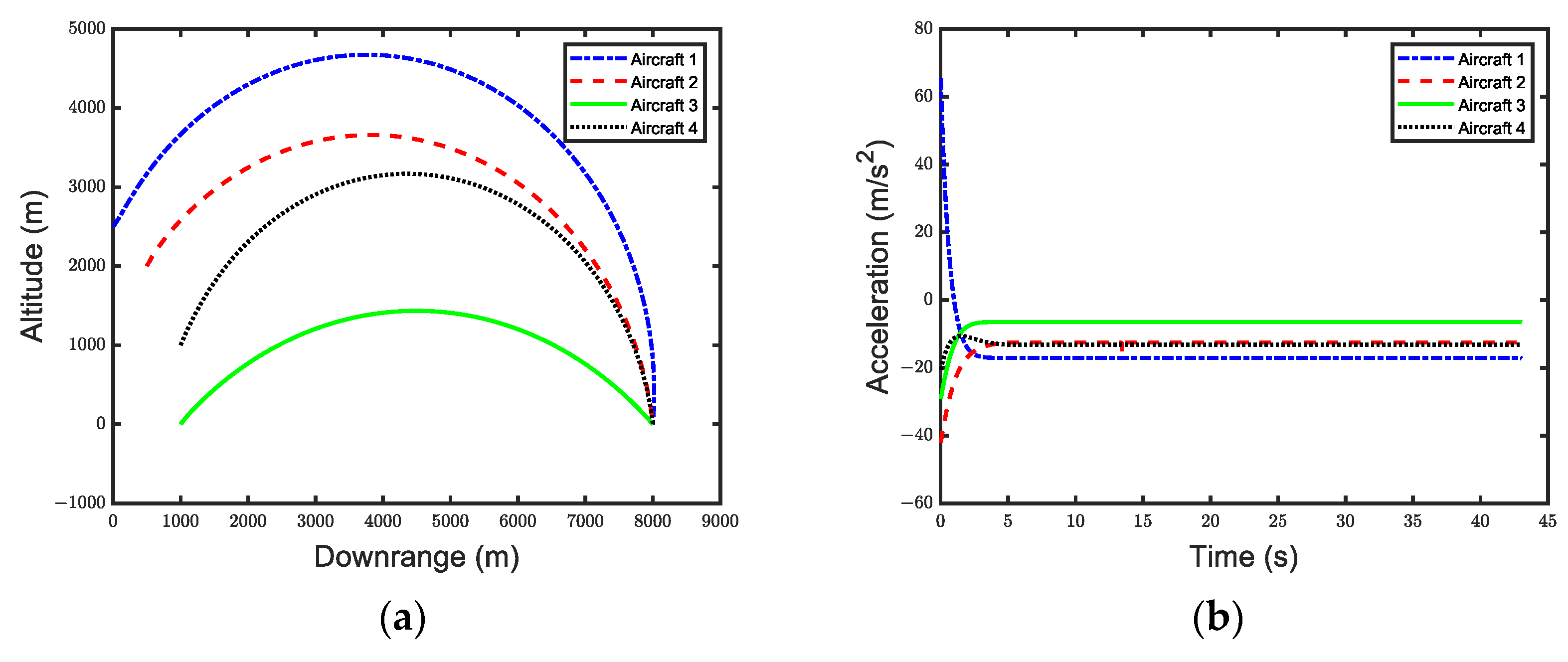
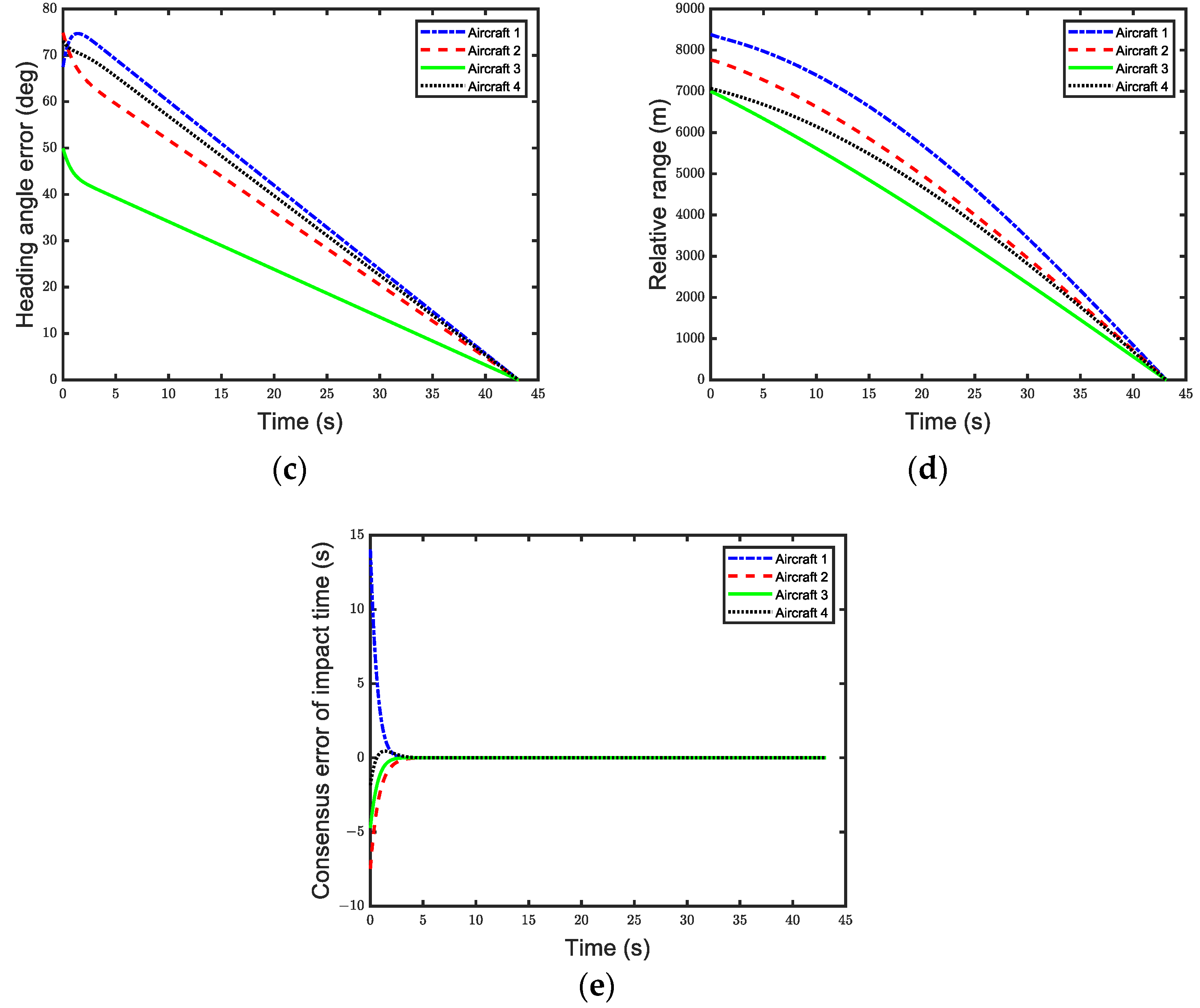
where t pre = 5   s . The simulation results are shown in Figure 3, where the blue, red, green, and black lines represent the results of Aircraft 1, 2, 3, and 4, respectively.
Figure 3a illustrates the flight trajectories of each aircraft during the cooperative arrival. It can be seen that they are all smooth trajectories, indicating that the guidance law can maintain stable flight conditions while executing the cooperative arrival mission.
Figure 3b shows the variation in aircraft acceleration over time. It is evident that the accelerations of all aircraft remain constant after time t = t pre = 5   s , aligning with the requirements of the design strategy.
Figure 3c displays the changes in the heading error angle. When t > 5   s , the heading angle changes linearly and converges to 0 at the same time, indicating that the aircraft have achieved cooperative arrival.
Figure 3d illustrates the variation in the flight distance. Together, these figures demonstrate that both the heading error angle and distance of the aircraft converge to zero at the same moment, successfully proving that the proposed guidance law can achieve cooperative guidance for multiple aircraft.
Figure 3e illustrates the consensus error in the flight time. When t > 5   s , the error converges to zero, indicating that the remaining flight time of all aircraft has achieved consistency.
Each aircraft’s flight time achieves consensus at the prescribed time t pre = 5   s . Compared to finite-time control laws, this guidance law enables precise control of cooperative timing, enhancing accuracy.

4.2. Directed Topology

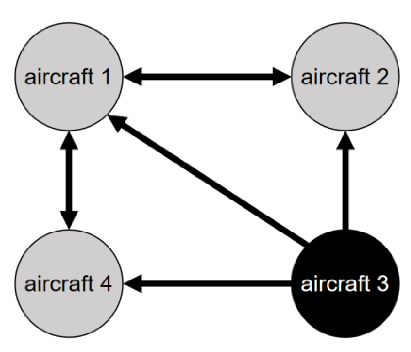
In this subsection, Aircraft 3 is selected as the leader, which can provide but not receive information. The remaining three aircraft can still communicate with each other. The communication topology is illustrated in Figure 4.
Consequently, the Laplacian matrix for Figure 4 is given by:
L = 2 1 0 1 1 3 1 1 0 1 2 1 0 0 0 0
First, the flight state of the leader Aircraft 3 is set, assuming that its acceleration a 0 remains constant during the flight. Consequently, the flight time t satisfies Equation (36). The detailed simulation parameters for each aircraft remain the same as in the undirected topology, and the specific parameters are listed in Table 1.
To ensure cooperation is achieved within the prescribed time, h max , λ min ( U ) , and ξ ( t ) are first set. Based on Lemma 4, h max = 2 and λ min ( U ) = 1 . 84 are calculated. The parameter ξ ( t ) must satisfy the conditions outlined in Lemma 4. Therefore, this paper designs ξ ( t ) in Equation (35) as follows:
ξ ( t ) = 1 cos ( π t 7 ) 2 , 0 t t pre ; 1 , t > t pre
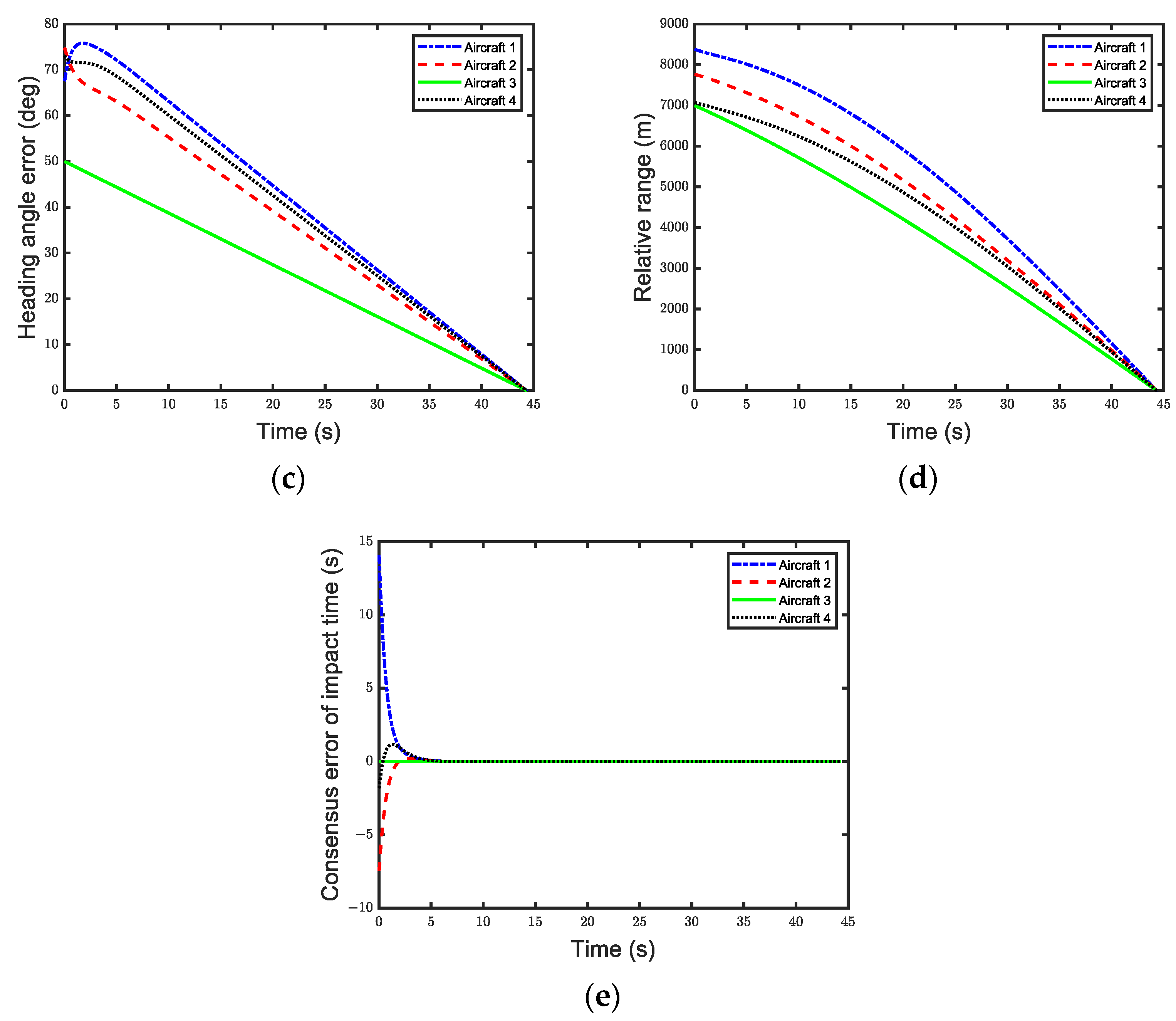
where t pre = 7   s . The simulation results are shown in Figure 5. The blue, red, green, and black lines represent the results of Aircraft 1, 2, 3, and 4, respectively.
Figure 5a illustrates the flight trajectories of each aircraft during the cooperative arrival. The smooth paths indicate that the guidance law can ensure stable flight conditions not only under undirected topology but also in directed topology scenarios.
Figure 5b shows the variation in aircraft acceleration over time. Since Aircraft 3 acts as the leader, its control parameter c i remains constant at 1 during the return phase, keeping the acceleration unchanged. The other aircraft adjust their control parameters based on Aircraft 3. It is evident that all aircraft achieve stable acceleration after time t = t pre = 7   s , fulfilling the requirements of the design strategy.
Figure 5c illustrates the changes in the heading error angle. When t > 7   s , the heading angle changes linearly and converges to 0 at the same time, indicating that the aircraft have achieved cooperative arrival.
Figure 5d shows the variation in flight distance. Together, these figures reveal that both the heading error angle and distance of the aircraft converge to zero at the same moment, successfully demonstrating that the proposed guidance law can achieve cooperative guidance for multiple aircraft under a directed topology.
Figure 5e illustrates the consensus error in the flight time. When t > 7   s , the error converges to zero, indicating that the remaining flight time of all aircraft has achieved consistency.
In summary, it is evident that under the proposed guidance law, each aircraft’s flight time can achieve consensus within the prescribed time. This simulation demonstrates that even in the presence of communication failures, the proposed guidance law can still be effectively applied to facilitate cooperative arrival.

5. Conclusions

This paper proposes a distributed cooperative guidance law under prescribed-time convergence. Unlike traditional control laws, this guidance law does not preset the arrival time during the design process but instead directly addresses the consensus on the flight time, making it suitable for more complex flight situations. Numerical simulations successfully demonstrate the precise control of cooperative timing under both undirected and directed topologies, improving the convergence speed of flight time consensus. Future work may consider further designing parameters to reduce the initial acceleration and enhance the safety and reliability of aircraft during flight.

Author Contributions

Conceptualization, A.S. and C.O.; methodology, A.S.; software, C.O.; validation, A.S., C.O. and Z.C.; formal analysis, C.O.; investigation, A.S.; resources, C.O.; data curation, A.S.; writing—original draft preparation, A.S.; writing—review and editing, Z.C.; visualization, A.S.; supervision, Y.L.; project administration, Z.C.; funding acquisition, Z.C. All authors have read and agreed to the published version of the manuscript.

Funding

The National Natural Science Foundation of China (No. 61903146).

Data Availability Statement

The data presented in this study are only available on request from the corresponding author due to privacy reasons.

Conflicts of Interest

The authors declare no conflict of interest.

References

  1. Tuncer, O.; Cirpan, H.A. Adaptive fuzzy based threat evaluation method for air and missile defense systems. Inf. Sci. 2023, 643, 119191. [Google Scholar] [CrossRef]
  2. Zeng, J.; Dou, L.; Xin, B. A joint mid-course and terminal course cooperative guidance law for multi-missile salvo attack. Chin. J. Aeronaut. 2018, 31, 1311–1326. [Google Scholar] [CrossRef]
  3. Lyu, T.; Guo, Y.; Li, C.; Ma, G.; Zhang, H. Multiple missiles cooperative guidance with simultaneous attack requirement under directed topologies. Aerosp. Sci. Technol. 2019, 89, 100–110. [Google Scholar] [CrossRef]
  4. In-Soo, J.; Jin-Ik, L.; Min-Jea, T. Impact-time-control guidance law for anti-ship missiles. IEEE Trans. Control Syst. Technol. 2006, 14, 260–266. [Google Scholar] [CrossRef]
  5. Jeon, I.-S.; Lee, J.-I.; Tahk, M.-J. Impact-Time-Control Guidance with Generalized Proportional Navigation Based on Nonlinear Formulation. J. Guid. Control Dyn. 2016, 39, 1885–1890. [Google Scholar] [CrossRef]
  6. Liu, S.; Liu, W.; Yan, B.; Liu, S.; Yin, Y. Impact Time Control Guidance Law for Large Initial Lead Angles Based on Sliding Mode Control. J. Phys. Conf. Ser. 2021, 2031, 012050. [Google Scholar] [CrossRef]
  7. Kim, H.-G.; Shin, J. Lyapunov-Based Impact Time Control Guidance Law with Performance Prediction. Aerospace 2023, 10, 308. [Google Scholar] [CrossRef]
  8. He, S.; Lee, C.-H.; Shin, H.-S.; Tsourdos, A. Optimal three-dimensional impact time guidance with seeker’s field-of-view constraint. Chin. J. Aeronaut. 2021, 34, 240–251. [Google Scholar] [CrossRef]
  9. Zhu, C.; Xu, G.; Wei, C.; Cai, D.; Yu, Y. Impact-Time-Control Guidance Law for Hypersonic Missiles in Terminal Phase. IEEE Access 2020, 8, 44611–44621. [Google Scholar] [CrossRef]
  10. Wang, N.; Wang, X.; Cui, N.; Li, Y.; Liu, B. Deep reinforcement learning-based impact time control guidance law with constraints on the field-of-view. Aerosp. Sci. Technol. 2022, 128, 107765. [Google Scholar] [CrossRef]
  11. Liu, Z.; Wang, J.; He, S.; Shin, H.-S.; Tsourdos, A. Learning prediction-correction guidance for impact time control. Aerosp. Sci. Technol. 2021, 119, 107187. [Google Scholar] [CrossRef]
  12. You, H.; Chang, X.; Zhao, J.; Wang, S.; Zhang, Y. Three-dimensional impact-angle-constrained fixed-time cooperative guidance algorithm with adjustable impact time. Aerosp. Sci. Technol. 2023, 141, 108574. [Google Scholar] [CrossRef]
  13. Zhang, W.; Yan, J.; Yan, B. Finite-Time Distributed Cooperative Guidance Law with Impact Angle Constraint. Int. J. Aerosp. Eng. 2023, 2023, 5568394. [Google Scholar] [CrossRef]
  14. Ye, T.; Yuan-li, C. A Cooperative Guidance Law for Multiple Missiles with Impact Time and Terminal Angle Constraints. In Proceedings of the 2019 Chinese Control and Decision Conference (CCDC), Nanchang, China, 3–5 June 2019; IEEE: Piscataway, NJ, USA, 2019; pp. 1504–1510. [Google Scholar]
  15. Chen, Z.; Chen, W.; Liu, X.; Cheng, J. Three-dimensional fixed-time robust cooperative guidance law for simultaneous attack with impact angle constraint. Aerosp. Sci. Technol. 2021, 110, 106523. [Google Scholar] [CrossRef]
  16. Gu, Z.; Wang, X.; Wang, Z. Fixed-Time Distributed Event-Triggered Cooperative Guidance Methods for Multiple Vehicles with Limited Communications to Achieve Simultaneous Arrival. Aerospace 2024, 11, 709. [Google Scholar] [CrossRef]
  17. Chen, Z.; Yu, J.; Dong, X.; Ren, Z. Three-dimensional cooperative guidance strategy and guidance law for intercepting highly maneuvering target. Chin. J. Aeronaut. 2021, 34, 485–495. [Google Scholar] [CrossRef]
  18. Zhang, P.; Zhang, X. Multiple missiles fixed-time cooperative guidance without measuring radial velocity for maneuvering targets interception. ISA Trans. 2022, 126, 388–397. [Google Scholar] [CrossRef]
  19. Ma, X.; Dai, K.; Zou, Y.; Yu, H.; Zhang, H.; Wang, X. Fixed-time anti-saturation grouped cooperative guidance law with state estimations of multiple maneuvering targets. J. Frankl. Inst. 2023, 360, 5524–5547. [Google Scholar] [CrossRef]
  20. Gao, J.; Li, X.; Zang, S.; Ma, J.; Zhang, J.; Yan, B. Adaptive Distributed Fixed-Time Cooperative Three-Dimensional Guidance Law for Multimissiles against Manoeuvring Target. Int. J. Aerosp. Eng. 2023, 2023, 4692840. [Google Scholar] [CrossRef]
  21. Chen, C.; Han, Y.; Zhu, S.; Zeng, Z. Prescribed-Time Cooperative Output Regulation of Heterogeneous Multiagent Systems. IEEE Trans. Ind. Inform. 2024, 20, 2432–2443. [Google Scholar] [CrossRef]
  22. Song, Y.; Ye, H.; Lewis, F.L. Prescribed-Time Control and Its Latest Developments. IEEE Trans. Syst. Man Cybern. Syst. 2023, 53, 4102–4116. [Google Scholar] [CrossRef]
  23. Shakouri, A.; Assadian, N. A Framework for Prescribed-Time Control Design via Time-Scale Transformation. IEEE Control Syst. Lett. 2022, 6, 1976–1981. [Google Scholar] [CrossRef]
  24. Xu, C.; Wu, B.; Zhang, Y. Distributed prescribed-time attitude cooperative control for multiple spacecraft. Aerosp. Sci. Technol. 2021, 113, 106699. [Google Scholar] [CrossRef]
  25. Bai, H.; Mei, S.; Dong, J. Hierarchical temporal sequence convergence in prescribed-time control for quadrotor UAVs under unknown dynamic disturbances. Aerosp. Sci. Technol. 2024, 148, 109094. [Google Scholar] [CrossRef]
  26. Miao, Q.; Zhang, K.; Jiang, B. Incremental fully actuated system approach-based prescribed-time fault-tolerant formation control of helicopters under multiple faults. Aerosp. Sci. Technol. 2024, 151, 109334. [Google Scholar] [CrossRef]
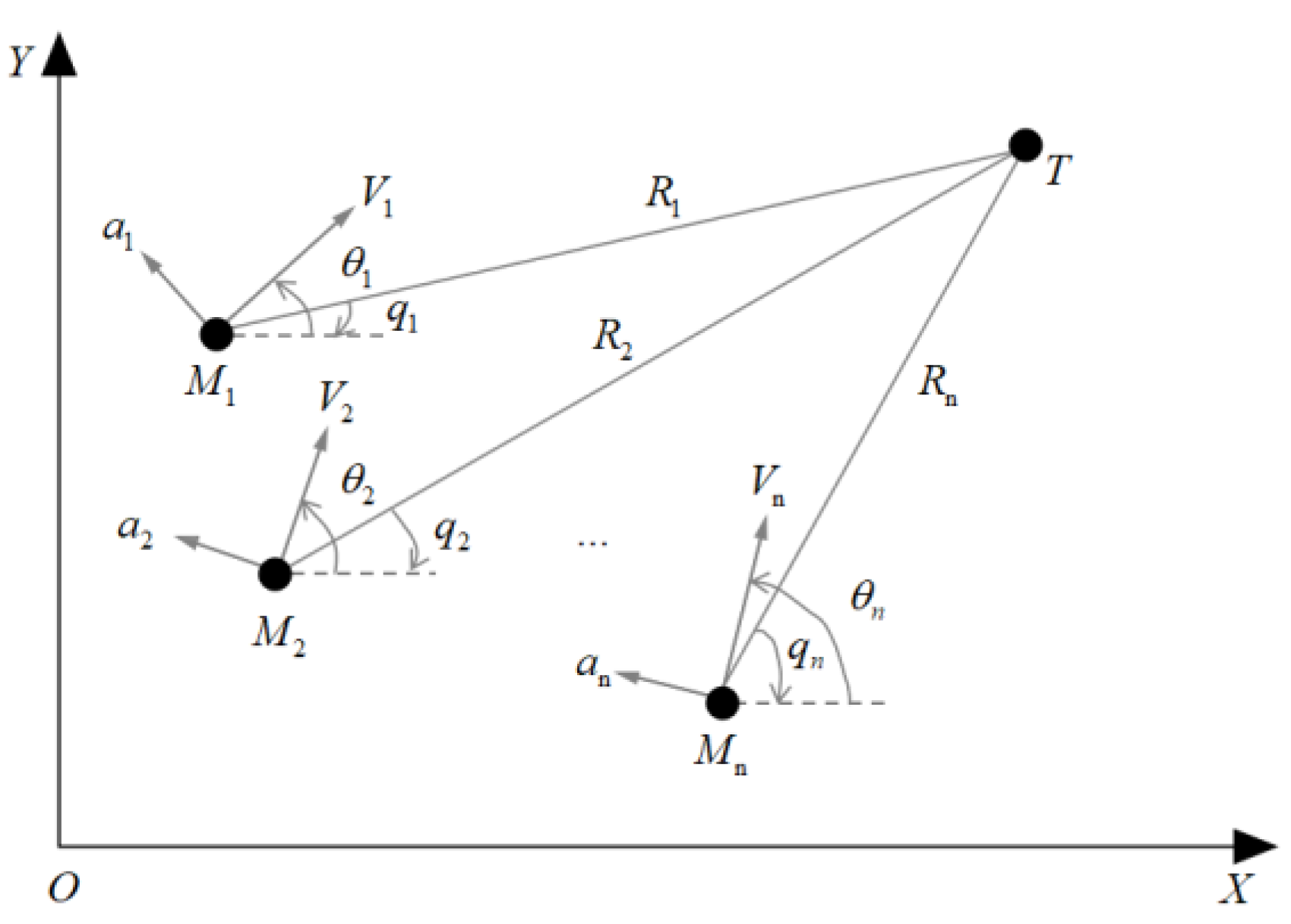
Figure 1. Schematic diagram of motion model.
Aerospace 12 00169 g001
Figure 2. Undirected and connected communication topology among aircraft.
Aerospace 12 00169 g002
Figure 3. Simulation results under undirected and connected communication topology. (a) Aircraft trajectory. (b) Lateral acceleration. (c) Heading error. (d) Range variation. (e) Consensus error of flight time.
Aerospace 12 00169 g003aAerospace 12 00169 g003b
Figure 4. Leader–follower communication topology among aircraft.
Aerospace 12 00169 g004
Figure 5. Simulation results under leader−follower communication topology. (a) Aircraft trajectory. (b) Lateral acceleration. (c) Heading error. (d) Range variation. (e) Consensus error of flight time.
Aerospace 12 00169 g005aAerospace 12 00169 g005b
Table 1. Initial parameters for the four aircraft.
Initial Relative Range (m)Velocity (m/s)Initial Heading Angle (deg)Initial LOS Angle (deg)
1832027050−17.37
2776023060−14.95
37000180500
4707022065−8.15
Disclaimer/Publisher’s Note: The statements, opinions and data contained in all publications are solely those of the individual author(s) and contributor(s) and not of MDPI and/or the editor(s). MDPI and/or the editor(s) disclaim responsibility for any injury to people or property resulting from any ideas, methods, instructions or products referred to in the content.