Article

The Application of Negative Poisson’s Ratio Metamaterials in the Optimization of a Variable Area Wing

State Key Laboratory of Mechanics and Control for Aerospace Structures, Nanjing University of Aeronautics and Astronautics, Nanjing 210016, China
*
Author to whom correspondence should be addressed.
Aerospace 2025, 12(2), 125; https://doi.org/10.3390/aerospace12020125
Submission received: 14 December 2024 / Revised: 27 January 2025 / Accepted: 3 February 2025 / Published: 7 February 2025
(This article belongs to the Section Aeronautics)

Abstract

:
Mechanical metamaterials, especially the cells with a negative Poisson’s ratio (NPR), have received much attention since they offer more deformability potential in morphing wings. This paper proposes a strategy for regulating the deformation of metamaterial cells based on the deformation form of the wing planform. The deformation of the wing shape was achieved through this strategy, with the main control factor of NPR. In light of the strategy, taking bi-directional re-entrant anti-tetrachiral (BRATC) metamaterial cells with NPR as an example, a scheme for BRATC metamaterial cells to regulate NPR is proposed. Driven by the same increase in wingspan (Δspan = 5%), the wing models, which are constructed based on the BRATC metamaterial cells with NPR characteristics at the different chord length increment at wing root (Δchord = 20%, 25%, and 30%), achieved an acceptable object-contour shape error (K = 1.29%, 1.40%, and 2.10%) with corresponding relative area increases (Ar = 15.5%, 18.13%, and 20.75%). Finally, the feasibility of the method is verified by experimentally measuring the deformation of the wing model.

1. Introduction

The aerodynamic performance of an aircraft is largely determined by its shape. As flight missions become increasingly diverse and complex, the design requirements for morphing aircraft are becoming more prominent [1,2]. A morphing aircraft can be defined as an aircraft that changes configuration to maximize its performance at radically different flight conditions [3]. The wings, which constitute the primary source of lift in the configuration of morphing aircraft, have the potential to markedly enhance overall aerodynamic performance, thus becoming the main object in the morphing aircraft field [4]. Among the various forms of shape morphing of aircraft wings [5,6,7,8,9,10,11], the variable span wing exhibits a notable variation in the reference area of the wing, which has a substantial impact on the lift and speed of the aircraft [12,13,14,15]. Concurrently, the wings must be capable of withstanding considerable dynamic loads and have certain requirements for strength and stiffness [16]. The traditional forms of span change are mainly two categories: telescoping [17,18,19,20,21,22,23] and folding [24]. Victor et al. [17] proposed a telescopic variable-span wing with one and two wing extensions deployed, which are actuated by a stepper motor and transmission rack. To not change the total unmanned aerial vehicle weight of the original configuration, a weight constraint was imposed for the sizing of the wing-box structure. The results indicate that an increase of 50% in the wingspan can enhance the aerodynamic efficiency of the unmanned aerial vehicle up to 15% and reduce the drag coefficient up to 6% compared with the baseline rectangular wing. Ajaj et al. [19] proposed the development of a novel multi-objective polymorphing wing capable of active span morphing and passive pitching for small unmanned aerial vehicles. The wingspan can be actively extended by up to 25% to enhance aerodynamic efficiency, whilst the passive pitch is utilized to alleviate gust and maneuver loads at off-design conditions and shift the lift distribution during 1 g flight. Both telescopic and foldable forms of wing design are afflicted by a common fundamental issue, namely the presence of discontinuous wing surfaces [25].
Metamaterials, with their strong designability and advantages over traditional materials, are expected to drive new developments in morphing-wing technology [26,27,28,29,30,31]. In recent years, metamaterial cells with zero Poisson’s ratio (ZPR) [32,33,34,35,36] have received the most attention in the application of span-change morphing wings. The application of metamaterial with ZPR property in morphing wings can only increase the wing area in one dimension [37,38], whereas the application of metamaterials with a negative Poisson’s ratio (NPR) property in morphing-wing structures can cause both spanwise and chordwise deformation, resulting in the two-dimensional deformation of the wing and greater potential for area variation. Presently, research on metamaterial cells with NPR characteristics based on morphing-wing applications mainly focuses on exploring the mechanical properties of metamaterials or conceptual wing design [39]. In the previous work at Refs [40,41], metamaterial cells with NPR properties were designed and the relationship between the mechanical properties of these cells and their geometric parameters was investigated and verified. To broaden the application of NPR on morphing wings, this article further explores and provides a new type of morphing-wing deformation.
This paper proposes a strategy for regulating the deformation of metamaterial cells based on the deformation form of the wing planform. In the light of finite element analysis, the concept of regional division is employed to divide the wing into N blocks. Based on this partitioning, the distribution law of NPR value in the wing is derived, thereby enabling the control of the deformation of the wing planform. In light of the strategy, taking bi-directional re-entrant anti-tetrachiral (BRATC) metamaterial [41] cells with NPR as an example, a scheme for BRATC metamaterial cells to regulate NPR is proposed. In this scheme, BRATC parameters are divided into two categories, and different adjustment methods are selected for each category to obtain a better contour of wing structure deformation. Concurrently, considering the bearing capacity of the wing, distributed spars are designed, and the bearing capacity is verified under a certain distributed air load in simulation. Finally, the deformation ability of the wing based on the BRATC metamaterial cell is verified through experiments.

2. Variable Area Wing Design

The metamaterial cells are defined as the fundamental functional units that constitute metamaterials, characterized by specific geometric shapes and sizes, which are arranged through manual design. When a metamaterial cell with a NPR is subjected to tension, it undergoes expansion deformation orthogonal to the loading direction, which has the potential for a larger variable area. To verify the application potential of metamaterial in morphing-wing structures, this paper adjusts the geometrical parameters to enable the wing to change from rectangular to trapezoid. The deformation demand of the wing and the deformation ability of the metamaterial cell are analyzed separately.

2.1. Strategy of Morphing Wing in Planform

2.1.1. Demand Analysis of Metamaterial Properties in Morphing Mechanism

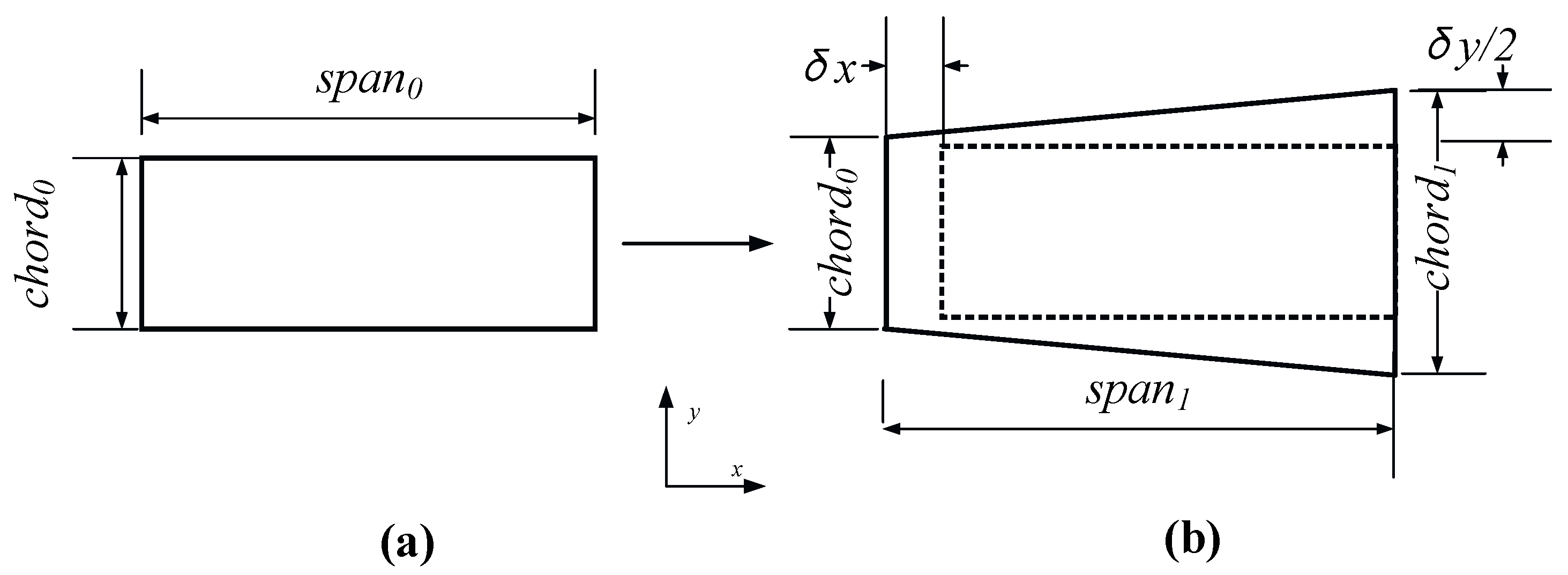
Based on the two-dimensional direction deformation mechanism, the concept of a shape-morphing wing in planform alternation is proposed, as shown in Figure 1. Due to the complete symmetry of the left and right wing structures, only the deformation of the left wing will be investigated below. A simplified diagram of shape morphing in planform at the left wing is shown in Figure 2, where the leading and trailing edge angles are kept equal after deformation to simplify the design. Figure 2a depicts the undeformed wing, exhibiting a rectangular contour with span length of span0 and chord length of chord0; Figure 2b depicts a deformed wing with a trapezoidal contour, where the span length is span1, the wing tip length is chord0, and the wing root length is chord1. The deformed wing has an increase in span and chord (wing root) of δx and δy, respectively. To define the deformed wing contour without dimensionalization, the relative variations in spanwise and chordwise (wing root) are Δspan and Δchord; seen in Equations (1) and (2).
Δ s p a n = δ x s p a n 0
Δ c h o r d = δ y c h o r d 0
The comparison of wing planform contour between undeformed and deformed states indicates that, unlike traditional span-change wings, both the wingspan and the chord are changed. Specifically, the chord length gradually increases from the wing tip to the wing root in a spanwise direction. This planform alternation can be achieved by metamaterial cells with the negative Poisson’s ratio (NPR) characteristic through tensile expansion.

2.1.2. Morphing Ability Analysis of NPR Metamaterial in Wing Planform

The deformation of the wing is achieved by a combination of metamaterial cells with NPR properties. In order to explore the regularity of the cells’ properties more clearly, an independent NPR metamaterial cell is initially selected as the subject of investigation. When the NPR metamaterial cell is subjected to a longitudinal tensile force, resulting in a strain εx, then deformation occurs in its y-axis direction, which can be represented as Δy. According to the definition of Poisson’s ratio, it can be written as:
Δ y = y 0 ε x ν x y
where y0 denotes the original length of the metamaterial cell along the y-axis. νxy denotes the Poisson’s ratio of the metamaterial cell.
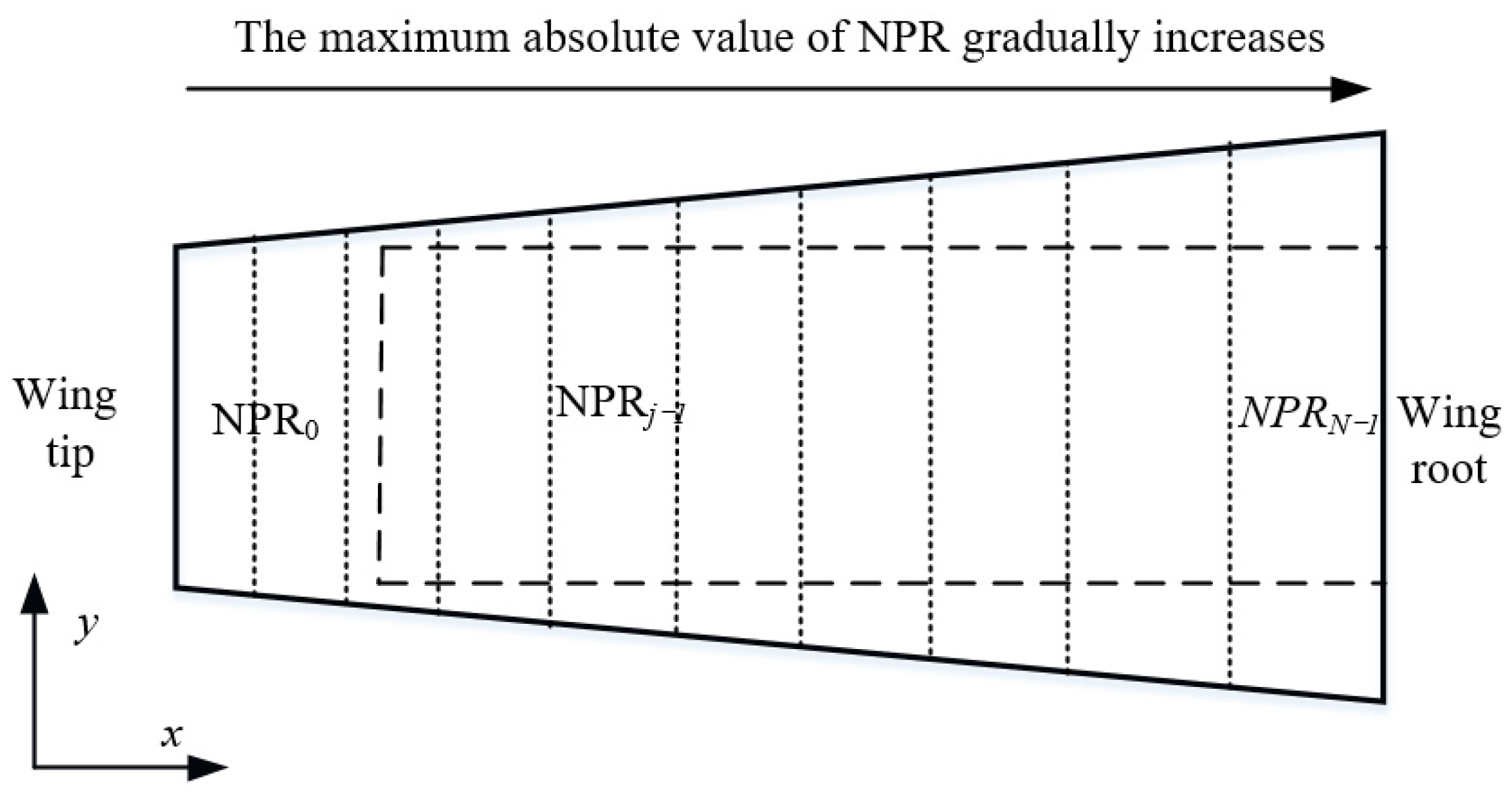
In order to compare the variation in NPR metamaterial cells along the spanwise direction clearly, the wing planform is gridded and divided into N blocks along the spanwise direction. Assuming that the εx of each cell is uniform, according to Equation (3), the deformation (Δy) along the y-axis of each column block is directly proportional to its Poisson’s ratio (νxy). The Poisson’s ratio of each block can be modified by the variable geometry of metamaterial cells. Based on the target shape, the length of the chord should be in a gradient distribution. In order to obtain the target shape, the deformability of the cells in the wing model should be in a gradient distribution. The Poisson’s ratio of a cell is closely related to its deformability. Therefore, the expected Poisson’s ratio of the cells in model should be in a gradient distribution. Then, based on the expected contour of the deformed wing, it is evident that the NPR of N blocks exhibits a specific change law along the spanwise, as depicted in Figure 3: maximum absolute value of NPR gradually increases from the wing tip to the wing root along the spanwise direction.
Moreover, the above two analyses of deformation occur only in a two-dimensional plane. In the wing, curvature generated by the airfoil undoubtedly increases the complexity of metamaterial cell design. To address this significant shortcoming, the range of metamaterial cells’ NPR value should be broadened to maximize the adjustable range of deformation.

2.2. Method of Morphing Wing Based on BRATC Metamaterial Cell

2.2.1. Deformation Analysis Scheme Based on BRATC Metamaterial Cell

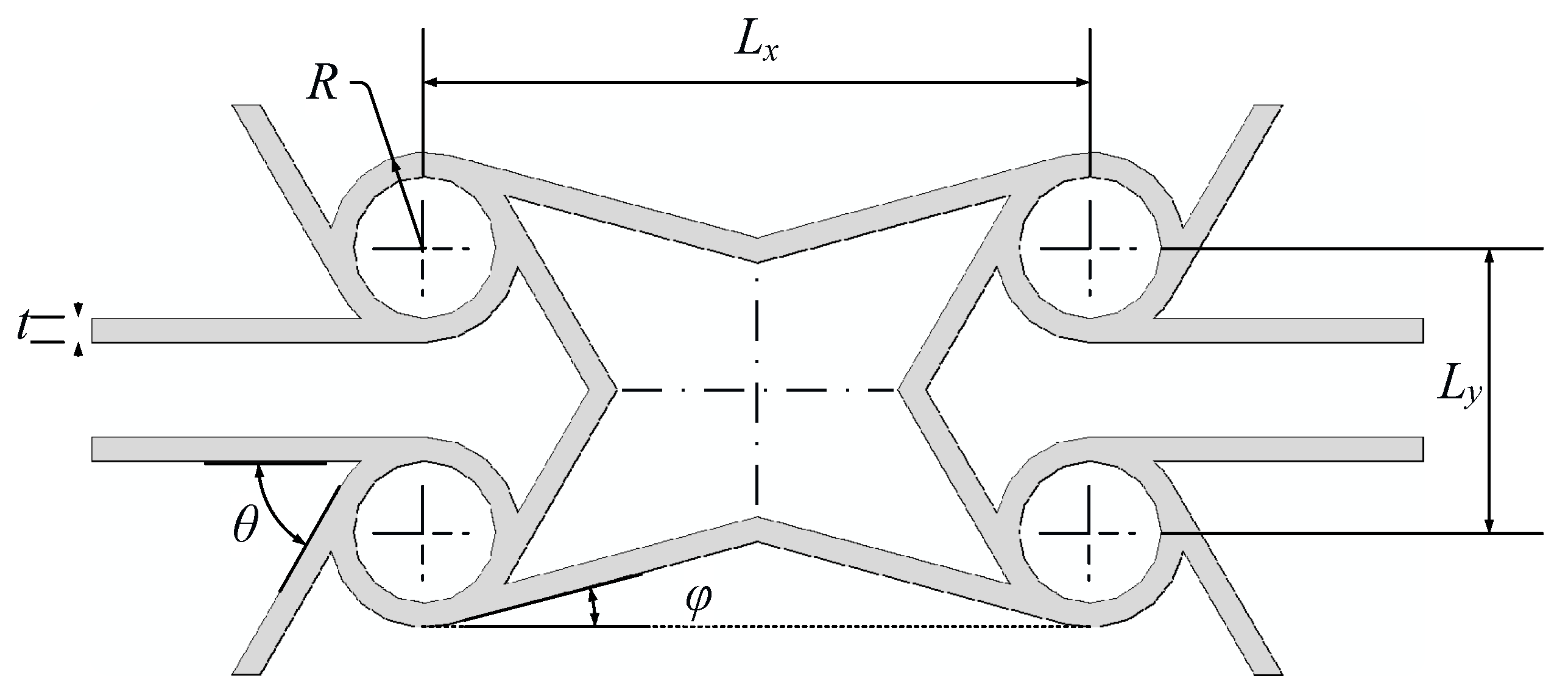
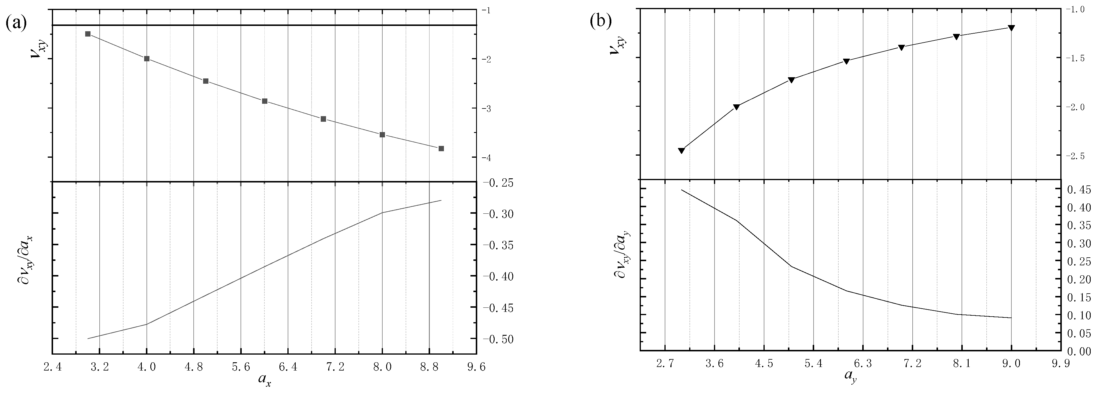
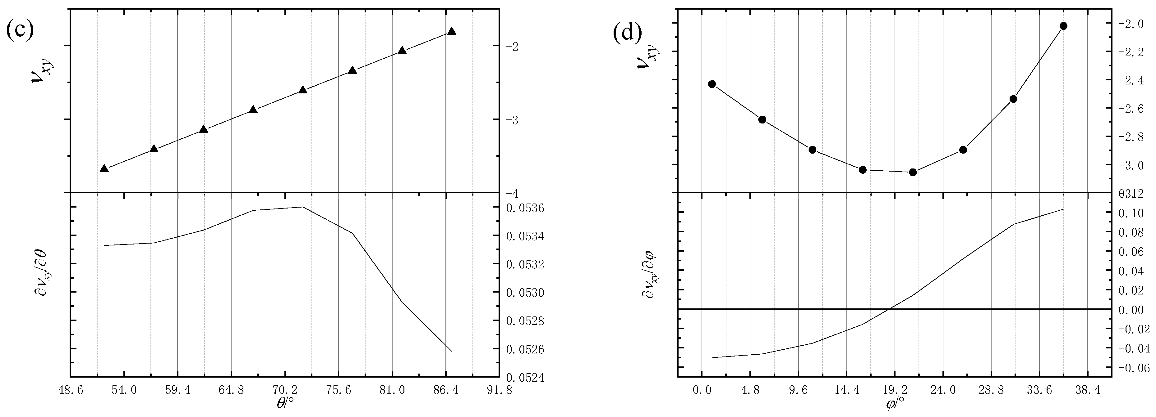
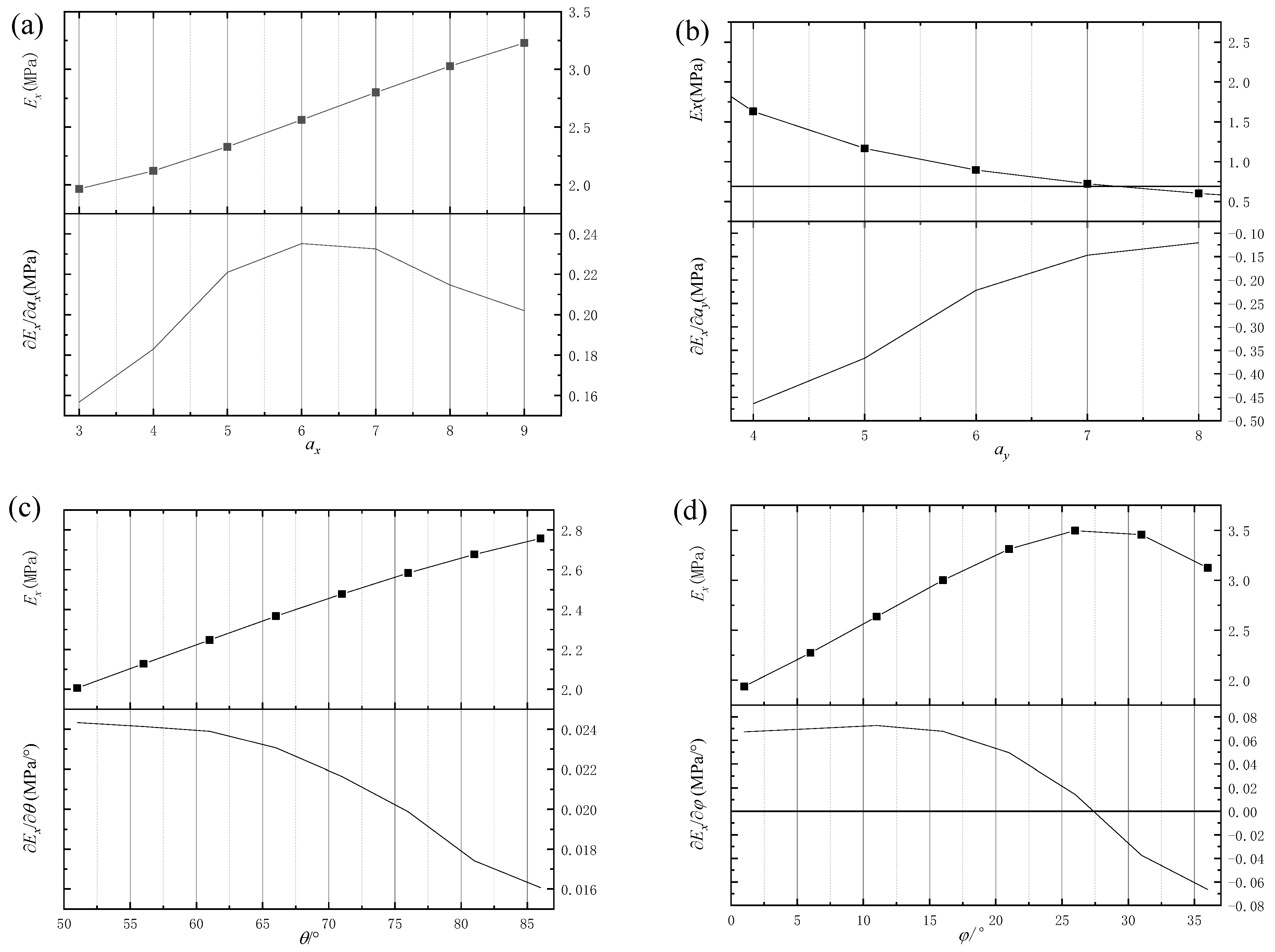
According to the requirements of the metamaterial deformation ability analyzed in Section 2.1.2, a kind of metamaterial cell with NPR characteristics (BRATC) is introduced, as shown in Figure 4. In the previous work [41], the metamaterial cell evolved from a honeycomb structure and has multiple geometrical parameters (ax, ay, θ, and φ) involved in the adjustment of NPR and elastic modulus (Ex). Furthermore, the parameter (b) that determines the stiffness level of the cell is not included in the NPR adjustment; that is, the BRATC cell has the design ability to ensure that the cell stiffness changes within a small range when adjusting the NPR value. According to the previous work [41], Figure 5 and Figure 6 show the sensitivity analysis of NPR and elastic modulus at geometrical parameters. It can be seen that the sensitivity differences between ax (ay) and θ (φ) are too large, and the influence of θ (φ) can be ignored. Thus, the values of NPR and elastic modulus changes allow for the categorization of parameters into two distinct categories: large-scale tuning parameters (ax, ay) and small-scale tuning parameters (θ, φ). The large-scale tuning parameters improve the span of NPR and elastic modulus adjustment, while small-scale tuning parameters improve the precision, making NPR and elastic modulus adjustment both efficient and smooth.
a x = L x R
a y = L y R
b = t R
In accordance with the strategy delineated in Section 2.1, it is imperative to ascertain that the stiffness of the metamaterial cells arranged in the wing plane is in the same order of magnitude. This involves guaranteeing that the parameter (b) of all metamaterial cells is kept in the same constant. Moreover, the large-scale tuning parameters are crucial in setting the benchmark value for the cell’s NPR. In accordance with the change law of ax and ay in regulating the value of NPR, when ay is maintained at a constant value, the value of NPR increases with an increase in ax. In order to facilitate a more intuitive comparison of the NPR difference between adjacent cells, it can set θ and φ as 90° and 0° in parameter initialization, respectively. In this configuration, the BRATC metamaterial cell degenerates into an anti-tetrachiral structure. According to reference [42], the value of Poisson’s ratio, which is closely related to its geometry parameters, can be simplified as Equation (7):
ν x y = a x a y
Finally, the NPR value is iteratively adjusted by small-scale tuning parameters (θ, φ) through optimization methods, so that the deformed wing structure iteratively converges to the target contour.

2.2.2. Morphing-Wing Model Based on BRATC Cell

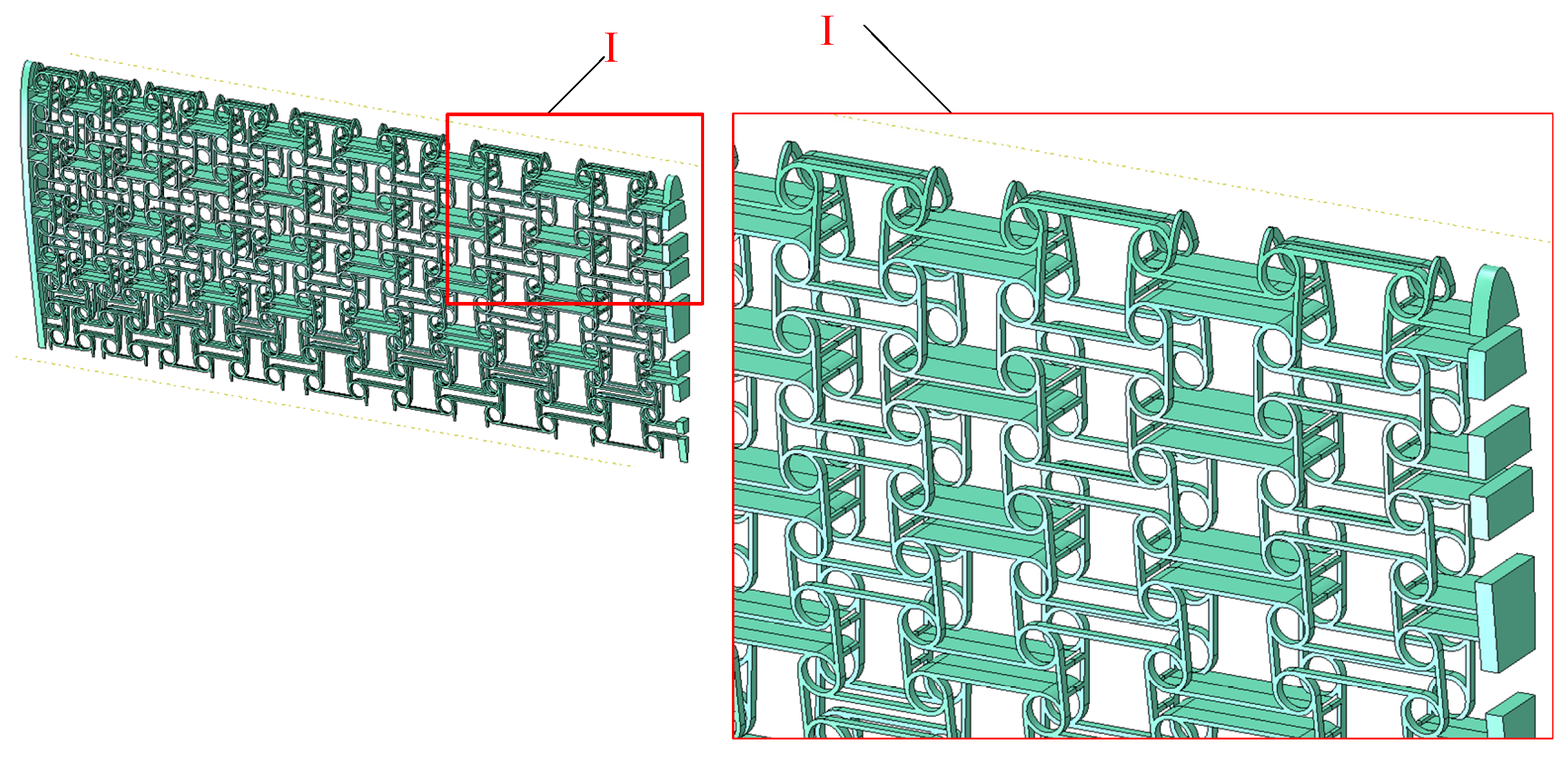
Based on the analysis in Section 2.2.1, the BRATC cell configuration and the definitions of the parameter are shown in Figure 7. The initial dimensionless parameters are shown in Table 1. The wing airfoil is based on the NACA0012 standard, with a single-sided wingspan of 360 mm and a chord length of 150 mm at both wing tip and wing root. In the FE modeling, the material of nylon is adopted with an elastic modulus of 1700 MPa and Poisson’s ratio of 0.42. In addition, considering load-bearing, distributed spars are introduced in the wing model, as shown in Figure 8.

2.2.3. Loads and Boundary Conditions in Wing Model

Based on the deformation of the wing’s planform, boundary conditions referred to as BC 1 are applied at the wing root (Face B and Face C). Simultaneously, displacement loads referred to as Load 1, are applied at the wing tip (Face A). The details of BC1 and Load 1 are shown in Table 2. To account for the wing’s load-bearing capacity, air loads distributed by pressure coefficients, referred to as Load 2, are utilized.
1.
Boundary conditions: BC1
As illustrated in Figure 9, due to active tensile deformation along the spanwise direction in the wing, Face B near the central axis of the wing root is fixed to avoid rigid body sliding. Meanwhile, Face C is free in the chordwise and fixed in the spanwise and out-of-plane directions.
2.
Displacement load: Load 1
The wing drive system exerts a force on the wing tips, resulting in the deformation of the wing in a spanwise direction. The displacement of the wing tip can be expressed as Dis_load:
D i s _ l o a d = s p a n 0 Δ s p a n x
where Δspan is set as 5%.
3.
Air load: Load 2
Set the flight altitude of the aircraft to 30 km and the cruising speed (V) to 60 m/s. In accordance with the international standard atmosphere, based on the value of altitude, the air pressure is 1.2 kPa, the air temperature is −46.5 °C, the air density (ρ) is 0.0184 kg/m3, the speed of sound is 301.7 m/s, and the air kinematic viscosity (ν) is 80.134 × 10⁻⁵ m2/s. Then, the Reynolds number (Re) is calculated to be 11,230 using Equation (9)
R e = V L v
where L is the characteristic length, usually the chord length of the wing, which is 0.15 m in this work.
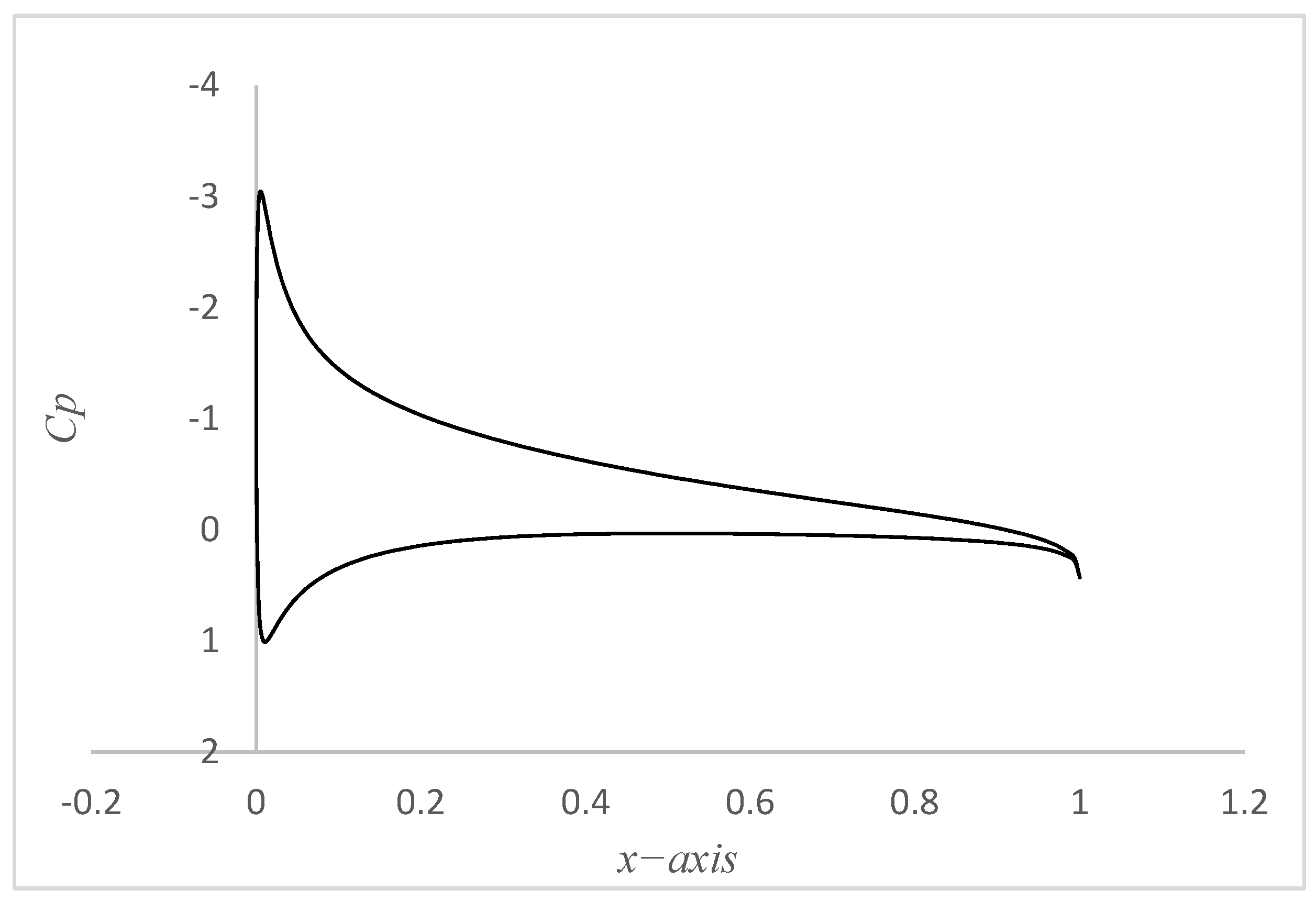
The NACA0012 airfoil, subjected to a Reynolds number of 11,230, is analyzed aerodynamically. The angle of attack (6.3°) that produces the maximum lift-to-drag ratio is selected, and the pressure coefficient Cp distribution on the airfoil, which is calculated by XFLR5 (version 6.61), is illustrated in Figure 10.
The pressure coefficient, Cp, is a field variable calculated from a NACA0012 airfoil with a chord length of one. That is, the value of Cp is distributed along the points on the curve of the NACA0012 airfoil, from wing tip to wing root. However, in this work, the chord0 is 150 mm. Accordingly, the number of points employed in the airfoil curve during the Cp calculation must be identical to the number of points utilized in the airfoil of the wing model. Through this setting, the value of Cp can be converted to the points of the airfoil curve in the wing model. Finally, according to the pressure distribution coefficient, the air load is applied on the surface of the wing structure.

2.2.4. Optimization of Morphing-Wing Contour Based on BRATC Cell

To evaluate the difference between the deformed wing contour and the target contour, a total of 4 N reference points were selected at the leading and trailing edges of the wing, as shown in Figure 11.
Extract the deformed coordinates (xj, yj) of the reference point through finite element software, and calculate the target vertical coordinate value Yj based on xj after deformation. The shape error (K) between the deformed wing contour and the target contour is defined as:
K = j n y j Y j 2 n c h o r d 1 2 2
where n is the total number of reference points.
The relative change rate of the wing area (Ar) is:
A r = 2 + Δ c h o r d y 1 + Δ s p a n x 2 1
As the large-scale tuning parameters (ax, ay) have already been set according to the specifications outlined in Section 2.2.2, the remaining step is to optimize the small-scale tuning parameters (θ, φ) as independent variables throughout the entire optimization process. In this work, Evol optimization algorithm [43] is applied. Evol is an evolution strategy based on the works of Rechenberg and Schwefel which mutates designs by adding a normally distributed random value to each design variable. The mutation strength (standard deviation of the normal distribution) is self-adaptive and changes during the optimization process. The algorithm only considers discrete design points, controlled via the minimum discrete step technique option (set as 2% of the design variable domain), and the evaluation is set as 100.

3. Optimization Results and Analysis

3.1. Morphing-Wing Contour Error

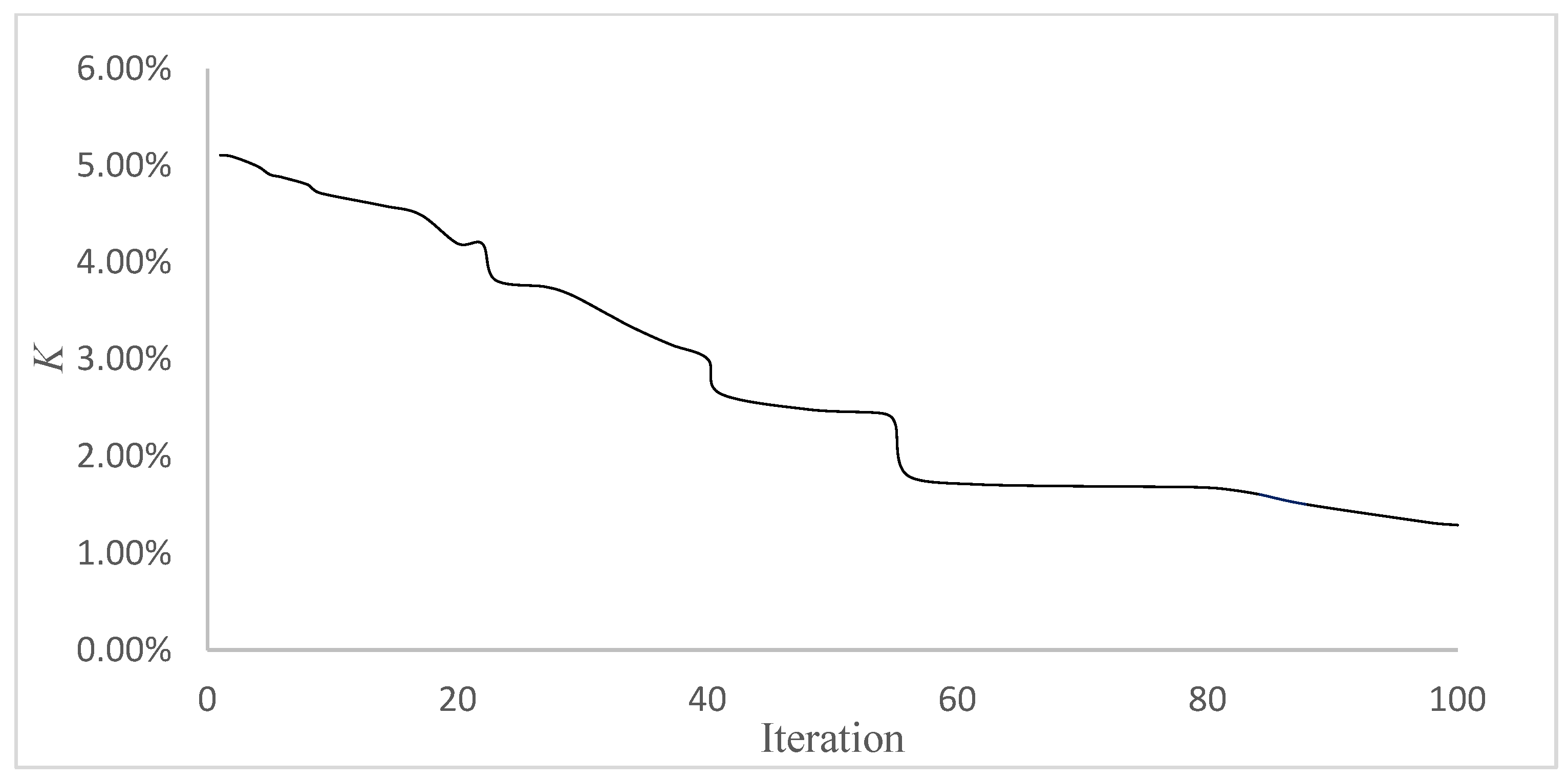
The wing contour with an Δchord of 20% is set as the target when the Δspan is 5% (Dis_load = 18 mm), and the minimum value of the K converged to 1.29% through the iteration of the optimization algorithm, achieving a 15% area increase in the wing. The structural geometric parameters of the optimal result are shown in Table 3, the comparison between the object contour and the optimal contour is shown in Figure 12, and the shape contour error against iteration is shown in Figure 13.
In Figure 12, it can be seen that the areas with large shape errors are mainly at the two ends of the wing, and the forms of errors at both ends are different: near the leftmost side (wing tip) in the figure, the wing contour is slightly larger than the object contour diagram. On the contrary, at the far right (wing root) of the figure, the wing contour is slightly smaller than the object contour. The locations of these two differences are exactly the positions of the upper and lower limits of the metamaterial cells’ NPR required by the deformation of the wing: the minimum near the wing tip and maximum near the wing root. It may be explained that the required deformation at the two positions may exceed the adjustment range for which the metamaterial cells can be supplied. In addition, there are fixed constraints (Face B) on the central axis of the wing at the wing root, which to some extent limit the deformation range of the metamaterial cells near the wing root.

3.2. Nephogram of Stress and Displacement

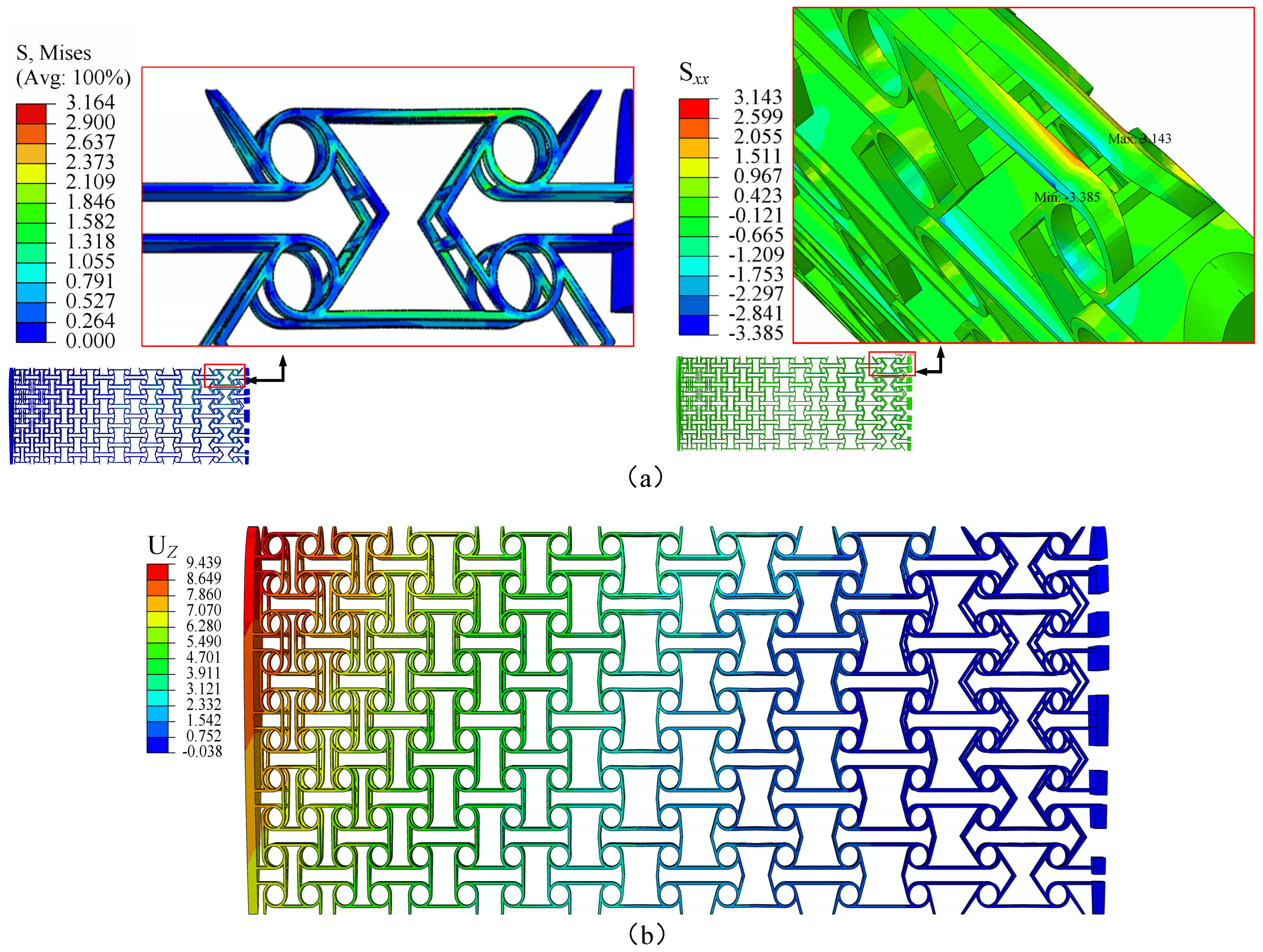
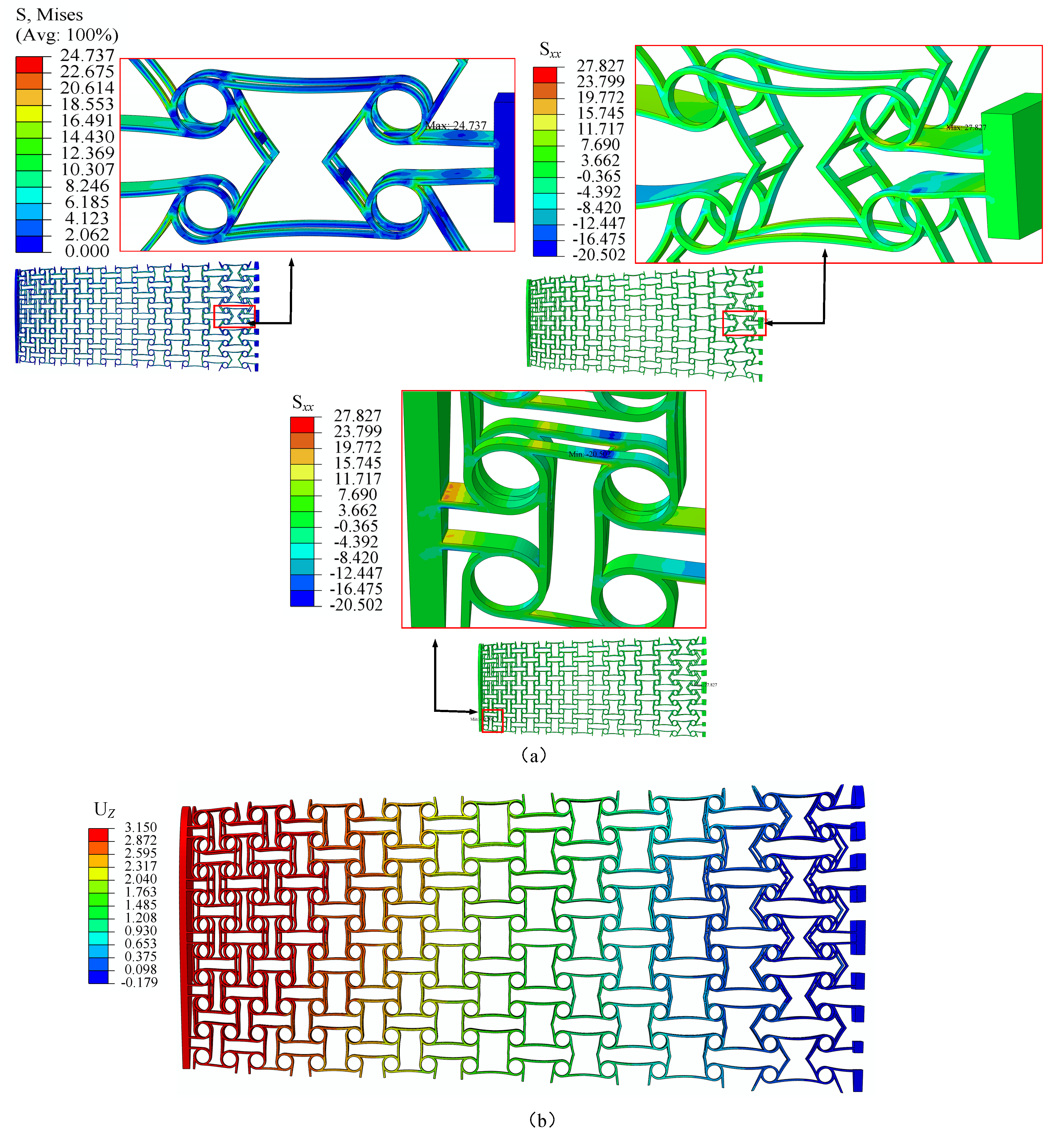
Based on data on flight conditions in this work, the pressure coefficient distribution is calculated by using the software XLFR 5 (version 6.61). According to pressure coefficient distribution, the distribution of air load in the wing model is calculated. In the FEM simulation, the displacement of the wing model under this air load is shown in Figure 14b. The maximum displacement (9.35 mm) on the z-axis is located at the wing tip near the leading edge. Considering that the stress values in the Syy and Szz directions are too small, only the stress distribution in the Sxx direction is presented. Figure 14 shows the distribution of cells’ stresses in the undeformed wing model. In these figures, the cell with maximum von Mises stress (3.16 MPa) is located at the leading edge near the wing root. The maximum tension stress (3.14 MPa) and maximum compression stress (3.39 MPa) occur in this cell as well. Figure 15 shows the distribution of cells’ stresses in the deformed wing model. In these figures, the cell, whose surface is subjected to boundary condition (Face B), has the maximum von Mises stress (24.74 MPa) and is located at the wing root. The cell with maximum compression stress (20.56 MPa) is located at the trailing edge near the wing tip. Observing the nephogram of displacement (Uz) of the undeformed wing, it can be seen that the maximum out-of-plane displacement is concentrated at the leading edge of the wing. The main reason is that according to the pressure coefficient distribution diagram, the aerodynamic load borne by the wing structure at the leading edge is relatively large. In addition, the stress values of the wing structure before and after deformation are within the range of material strength.

3.3. The Airfoil Along Spanwise Direction

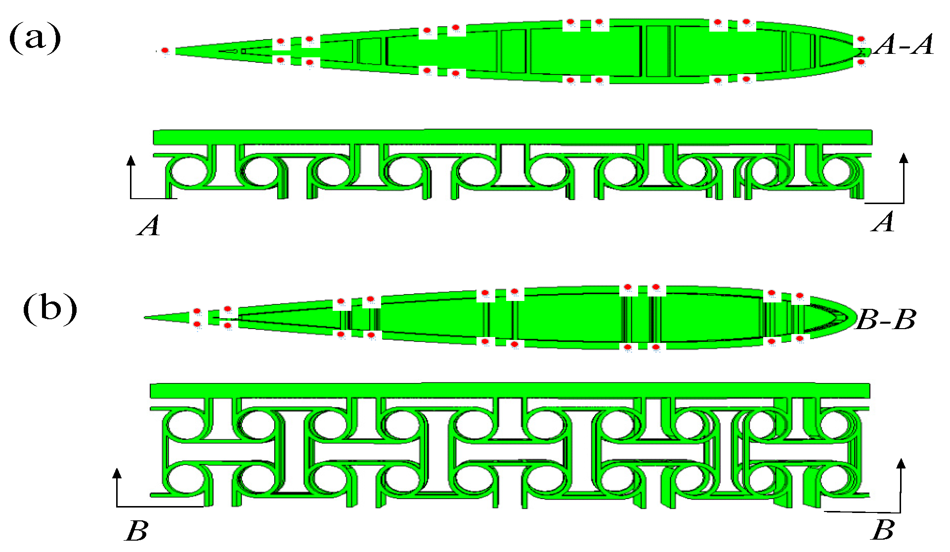
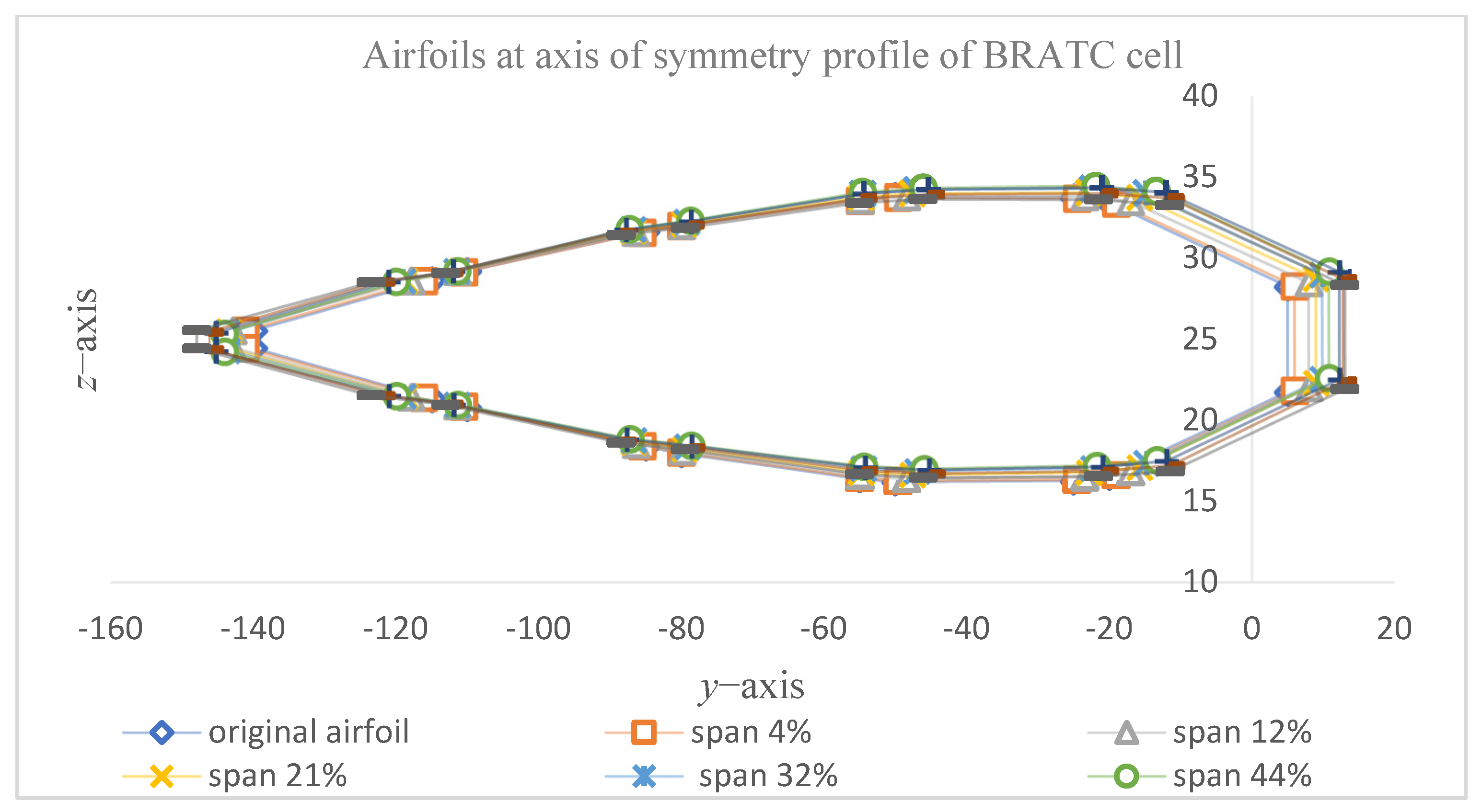
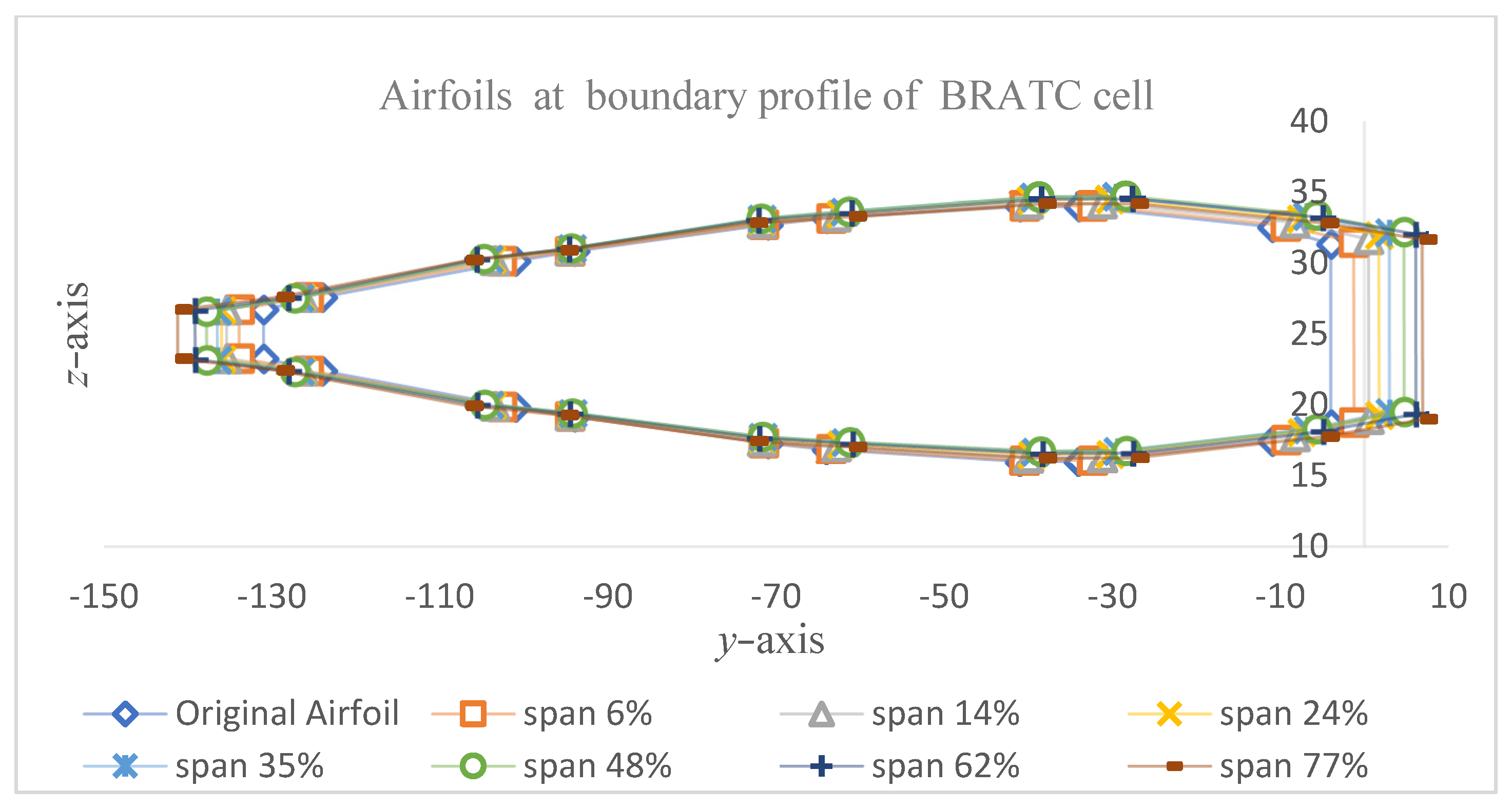
The wing shape mainly affects the lift, drag, and flight performance of an aircraft. In order to observe the changes in wing shape before and after deformation, the airfoils are sampled from two types of positions along the spanwise direction in simulation: airfoils at the axis of the symmetry profile of the BRATC cell and airfoils at the boundary profile of the BRATC cell. The examples of the airfoils are shown in Figure 16a,b. Each type of airfoil has the same initial shape, and the same kind of airfoil is distinguished by the distance ratio from its position to the wing tip to the wingspan (span0), shown in Figure 17 and Figure 18. By observing the two figures, it can be observed that the changes in the airfoil are mainly concentrated at the leading and trailing edges: the leading edge mostly undergoes displacement along the positive y-axis direction, while the trailing edge undergoes displacement towards the negative y-axis direction. The main reason for this is likely due to the boundary conditions at the wing root, where the face (Face B) is fixed, limiting the movement of the surrounding sampling points along the y-axis. Although metamaterials with NPR can increase the area of wings in two dimensions, they also cause certain changes in wing airfoil.

3.4. Comparison of Object Contours with Different Taper Ratios

When Δchord is set to 20%, 25%, and 30%, respectively, the wing-shape contour error (K) and relative area (Ar) are calculated, shown in Table 4. By observing the data in the table, it was found that the object contour deformation with different taper ratios both achieved acceptable contour changes, with wing-shape contour errors of 1.29%, 1.40%, and 2.02%, respectively. At the same time, the wing area increased by 15.50%, 18.13%, and 20.75%, respectively. Comparing Figure 19a–c, it can be observed that the areas with significant contour errors are both located at the wing root and wing tip. By comparing the changes in K values, it can be inferred that the main factor causing the increase in K is the increase in contour error at the wing root. This may be attributed to the fact that the factor of boundary constraints at the wing root has already become the major factor compared to the factor of deformation ability of the BRATC cell.

4. Validation Experiment

4.1. Experimental Equipment

The wing structure with the optimal geometric parameters is selected as the sample for deformation verification experiments when the Δchord is set as 20%. Figure 20 illustrates the wing sample, drive system, and aluminum profile bracket. Figure 20a is a schematic diagram, while Figure 20b is a physical image. Wing-root fixation can be classified into two categories: fixed to ball slider and fixed to bracket. The ball slider is mounted on the linear guide rail, whereas the bracket is secured to the ground. In the drive system, dual drive rods are utilized, with the left end connected to the wing tip and the right end connected to the drive motor through a coupling, which passes through a linear roller bearing in the middle.

4.2. Results of Experiment

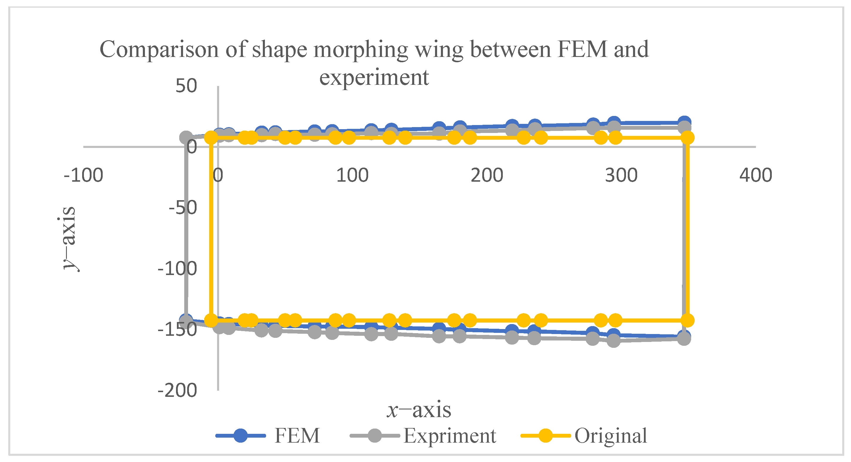
By driving the wing with dual motors simultaneously, the wing tip is moved outward by 18 mm (5% of span length) along the spanwise direction. The images of the wing structure before and after deformation are shown in Figure 21. The coordinates of the reference points were obtained through the pixel extraction method of the image in the experiment and subsequently compared with the simulation image, as illustrated in Figure 11. In the pixel sampling measurement, in order to ensure measurement accuracy, pixel photos are taken at the same distance from the wing model. In the experiment, the wing model is photographed together with the ruler to verify that the ratio of lengths to pixel dots is accurate.
Figure 22 illustrates that the positions of contour error are essentially analogous between the experimental and simulation results. At the leading edge of the wing, the average distance between the experimental and simulated values of the y-axis coordinates of the sampled points is 2.6 mm, with a maximum value of 4.1 mm near the wing root. At the trailing edge of the wing, the average distance between the experimental and simulated values of the y-axis coordinates of the sampled points is 3.2 mm, with a maximum value of 5.2 mm near the wing root. In the previous work [41], compared with the geometric parameters, the influence of the strain (εx) on NPR can be neglected. However, the deformation of a cell is affected by the boundary conditions, which makes a large deformation error near the wing root. Thus, the optimization method is used to fine-tune the deformations at the wing root to meet the requirements of shape contour error. Under the condition of smooth sliding at the wing root, the deformed wing exhibits an approximate area change of 16.7% in the experiment, which is approaching the 15.5% area change observed in the simulation. Furthermore, the contour errors of FEM results are obtained in the method of optimization. By setting convergence conditions (contour error less than 5% and the number of iterations exceeds 100), a wing structure that satisfies the conditions is obtained. Thus, when the convergence conditions are fulfilled, the optimization is stopped. In the FEM, the value of contour error (1.29%) is verified, which is less than 5%. The result (4.69%) in the experiment also meets the requirement of the contour error, verifying the feasibility of the method.

5. Conclusions

This article proposes a strategy based on a characteristic of NPR as the main control variable to address the deformation requirements of non-traditional span-change wing shapes. Based on the strategy, a regular scheme for adjusting the value of NPR by variable geometry in the morphing wing is obtained at the assumption of uniform elastic modulus. Inspired by the strategy, the sensitivity of the mechanical properties (NPR and elastic modulus) of BRATC metamaterial cells to their geometric parameters was analyzed. According to different sensitivity levels, BRATC geometric parameters are divided into two categories (one is the initial value of the optimization algorithm based on the distribution law of NPR in the wing, and the other is the control factor of the optimization algorithm), and are independently controlled. At different target contours (Δchord = 20%, 25%, and 30%), the morphing-wing models, which are constructed based on BRATC metamaterial cells with NPR characteristics, achieved acceptable object contour shape errors (K = 1.29%, 1.40%, and 2.10%). Finally, a deformability verification experiment is conducted on the optimal wing structure without considering the effect of air load. The experimental results demonstrate that the wing-shape contour error value (K) of the deformed wing is 4.69% and there is a relative area (Ar) increase of 16.7%, showing the application potential of the NPR metamaterial cell (BRATC) in morphing-wing structures.

Author Contributions

Conceptualization, H.W. and C.Z.; methodology, H.W.; software, H.W.; validation, H.W., C.Z. and C.W.; formal analysis, C.W.; investigation, H.W.; resources, J.Q.; data curation, C.W.; writing—original draft preparation, H.W.; writing—review and editing, H.W.; visualization, C.Z. and C.W.; supervision, J.Q.; project administration, J.Q.; funding acquisition, J.Q. All authors have read and agreed to the published version of the manuscript.

Funding

This work was supported by National Key Research and Development Program of China (2021YFB3400100), Natural Science Foundation of Jiangsu Province (BK20220133).

Data Availability Statement

The data presented in this study are available on request from the corresponding author.

Conflicts of Interest

The authors declare no conflicts of interest.

Abbreviations

Acronyms
NPRnegative Poisson’s ratio
BRATCbi-directional re-entrant anti-tetrachiral
Nomenclature
span0Span of undeformed wing
chord0Chord of undeformed wing
chord1Chord of deformed wing at wing root
span1Span of deformed wing
δxThe increase in spanwise
δyThe increase in chordwise (wing root)
ΔspanRelative variations in spanwise
ΔchordRelative variations in chordwise at wing root
εxStrain of a metamaterial cell
ΔyDeformation in y-axis direction of a metamaterial cell
y0Original length of the metamaterial cell along y-axis
νxyPoisson’s ratio of the metamaterial cell.
axNondimensionalized length of a BRATC cell
ayNondimensionalized width of a BRATC cell
bNondimensionalized height of a BRATC cell
θAn angle in a BRATC cell
φAn angle in a BRATC cell
Dis_loadDisplacement load
VCruising speed
ρAir density
vAir kinematic viscosity
ReReynolds number
CpPressure coefficient
CLLift coefficient
SReference wing surface area in xy plane
LLift
KShape error
ArRelative change rate of wing area

References

  1. Bae, J.S.; Seigler, T.M.; Inman, D.J. Aerodynamic and Static Aeroelastic Characteristics of a Variable-Span Morphing Wing. J. Aircr. 2005, 42, 528–534. [Google Scholar] [CrossRef]
  2. Chu, L.; Qi, L.I.; Feng, G.U.; Xintian, D.U.; Yuqing, H.E.; Deng, Y. Design, modeling, and control of morphing aircraft: A review. Chin. J. Aeronaut. 2022, 35, 220–246. [Google Scholar] [CrossRef]
  3. Jha, A.K.; Kudva, J.N. Morphing aircraft concepts, classifications, and challenges. In Smart Structures and Materials 2004: Industrial and Commercial Applications of Smart Structures Technologies; SPIE: San Diego, CA, USA, 2004; Volume 5388, pp. 213–224. [Google Scholar] [CrossRef]
  4. Ajaj, R.M.; Parancheerivilakkathil, M.S.; Amoozgar, M.; Friswell, M.I.; Cantwell, W.J. Recent developments in the aeroelasticity of morphing aircraft. Prog. Aerosp. Sci. 2021, 120, 100682. [Google Scholar] [CrossRef]
  5. Yuzhu, L.I.; Wenjie, G.E.; Zhou, J.; Zhang, Y.; Zhao, D.; Wang, Z.; Dong, D. Design and experiment of concentrated flexibility-based variable camber morphing wing. Chin. J. Aeronaut. 2022, 35, 455–469. [Google Scholar] [CrossRef]
  6. Zhang, H.; Zhang, Z.; Song, C.; Yang, C. A morphing wing with cellular structure of non-uniform density. Smart Mater. Struct. 2021, 30, 105005. [Google Scholar] [CrossRef]
  7. Li, D.; Guo, S.; Aburass, T.O.; Yang, D.; Xiang, J. Active control design for an unmanned air vehicle with a morphing wing. Aircr. Eng. Aerosp. Technol. Int. J. 2016, 88, 168–177. [Google Scholar] [CrossRef]
  8. Ozbek, E.; Ekici, S.; Karakoç, T.H. A comprehensive review of state-of-art FishBAC—Fishbone active camber morphing wing surfaces–: A promising morphing method. Aircr. Eng. Aerosp. Technol. 2024, 96, 983–993. [Google Scholar] [CrossRef]
  9. Kim, Y.; Jo, Y. Development of two types of in-plane motion actuators with modular design and application to morphing wings. Mech. Adv. Mater. Struct. 2024, 31, 12183–12199. [Google Scholar] [CrossRef]
  10. Karagiannis, D.; Stamatelos, D.; Kappatos, V.; Spathopoulos, T. An investigation of shape memory alloys as actuating elements in aerospace morphing applications. Mech. Adv. Mater. Struct. 2017, 24, 647–657. [Google Scholar] [CrossRef]
  11. Geva, A.; Abramovich, H.; Arieli, R. Investigation of a Morphing Wing Capable of Airfoil and Span Adjustment Using a Retractable Folding Mechanism. Aerospace 2019, 6, 85. [Google Scholar] [CrossRef]
  12. Ajaj, R.; Friswell, M.; Flores, E.S.; Little, O.; Isikveren, A. Span Morphing: A Conceptual Design Study. In Proceedings of the 53rd AIAA/ASME/ASCE/AHS/ASC Structures, Structural Dynamics and Materials Conference, Honolulu, HI, USA, 23–26 April 2012; Volume 2012, p. 1510. [Google Scholar]
  13. Ajaj, R.M.; Friswell, M.I.; Bourchak, M.; Harasani, W. Span morphing using the GNATSpar wing. Aerosp. Sci. Technol. 2016, 53, 38–46. [Google Scholar] [CrossRef]
  14. Elelwi, M.; Calvet, T.; Botez, R.M.; Dao, T.M. Wing component allocation for a morphing variable span of tapered wing using finite element method and topology optimisation—Application to the UAS-S4. Aeronaut. J. 2021, 125, 1313–1336. [Google Scholar] [CrossRef]
  15. Elelwi, M.; Kuitche, M.A.; Botez, R.M.; Dao, T.M. Comparison and analyses of a variable span-morphing of the tapered wing with a varying sweep angle. Aeronaut. J. 2020, 124, 1146–1169. [Google Scholar] [CrossRef]
  16. Ajaj, R.M.; Friswell, M.I.; Flores, E.I.S.; Keane, A.; Isikveren, A.T.; Allegri, G.; Adhikari, S. An integrated conceptual design study using span morphing technology. J. Intell. Mater. Syst. Struct. 2014, 25, 989–1008. [Google Scholar] [CrossRef]
  17. Alulema, V.H.; Valencia, E.A.; Toapanta, E.; Guailla, C.; Pazmio, M. Performance Assessment of a Variable-Span Morphing Wing Small UAV for High Altitude Surveillance Missions. In Proceedings of the AIAA Propulsion and Energy 2020 Forum, Virtual Event, 24–28 August 2020; Volume 2020, p. 3962. [Google Scholar] [CrossRef]
  18. Huang, C.; Yang, C.; Wu, Z.; Tang, C. Variations of flutter mechanism of a span-morphing wing involving rigid-body motions. Chin. J. Aeronaut. 2018, 31, 490–497. [Google Scholar] [CrossRef]
  19. Ajaj, R.M.; Parancheerivilakkathil, M.S.; Amoozgar, M. ASAPP: A polymorphing wing capable of Active Span extension And Passive Pitch. In Proceedings of the AIAA Scitech 2021 Forum, Virtual Event, 11–15 & 19–21 January 2021; Volume 2021, p. 0621. [Google Scholar] [CrossRef]
  20. Haider, Z.; Ajaj, R.M.; Seneviratne, L. On the Aeroelasticity of the Active Span and Passive Pitching Polymorphing Wing: Effect of Morphing Rate. Aerospace 2023, 10, 57. [Google Scholar] [CrossRef]
  21. Haider, Z.; Ajaj, R.M.; Seneviratne, L. On the Aeroelasticity of the Active Span and Passive Pitching Polymorphing Wing: A Parametric Study. Aerospace 2022, 9, 483. [Google Scholar] [CrossRef]
  22. Beaverstock, C.S.; Woods, B.K.S.; Fincham, J.H.S.-M.; Friswell, M.I. Performance Comparison between Optimised Camber and Span for a Morphing Wing. Aerospace 2015, 2, 524–554. [Google Scholar] [CrossRef]
  23. Parancheerivilakkathil, M.S.; Haider, Z.; Ajaj, R.M.; Amoozgar, M. A Polymorphing Wing Capable of Span Extension and Variable Pitch. Aerospace 2022, 9, 205. [Google Scholar] [CrossRef]
  24. Sun, J.; Du, L.; Scarpa, F.; Liu, Y.; Leng, J. Morphing wingtip structure based on active inflatable honeycomb and shape memory polymer composite skin: A conceptual work. Aerosp. Sci. Technol. 2021, 111, 106541. [Google Scholar] [CrossRef]
  25. Tarnowski, A. Morphing wing with skin discontinuity—Kinematic concept. Aircr. Eng. Aerosp. Technol. 2017, 89, 535–546. [Google Scholar] [CrossRef]
  26. Avila, A.; Avila, J.; Chaves, F. A Morphological Study on Cellular Composites with Negative Poisson Ratio. In Proceedings of the 44th AIAA/ASME/ASCE/AHS/ASC Structures, Structural Dynamics, and Materials Conference, Norfolk, VA, USA, 7–10 April 2003; p. 1951. [Google Scholar]
  27. Boston, D.M.; Arrieta, A.F. Multistable Honeycomb Architecture for Spanwise Wing Morphing. In Proceedings of the AIAA Scitech 2021 Forum, Virtual Event, 11–15 & 19–21 January 2021; p. 0479. [Google Scholar]
  28. Boston, D.M.; Phillips, F.R.; Henry, T.; Arrieta, A.F. Aeroelastic analysis of spanwise morphing wing with multistable honeycomb. In Proceedings of the AIAA SCITECH 2022 Forum, San Diego, CA, USA, 3–7 January 2022; p. 0319. [Google Scholar]
  29. Boston, D.M.; Phillips, F.R.; Henry, T.C.; Arrieta, A.F. Spanwise wing morphing using multistable cellular metastructures. Extrem. Mech. Lett. 2022, 53, 101706. [Google Scholar] [CrossRef]
  30. Han, Z.; Wang, Z.; Wei, K. Shape morphing structures inspired by multi-material topology optimized bi-functional metamaterials. Compos. Struct. 2022, 300, 116135. [Google Scholar] [CrossRef]
  31. Yokota, K.; Barthelat, F. Design guidelines for the morphing of stiff lattice materials. Mech. Adv. Mater. Struct. 2023, 31, 10070–10080. [Google Scholar] [CrossRef]
  32. Olympio, K.; Gandhi, F. Zero-v Cellular Honeycomb Flexible Skins for One-Dimensional Wing Morphing. In Proceedings of the 48th AIAA/ASME/ASCE/AHS/ASC Structures, Structural Dynamics, and Materials Conference, Honolulu, HI, USA, 23–26 April 2007; Volume 2007, p. 1735. [Google Scholar]
  33. Zadeh, M.N.; Dayyani, I.; Yasaee, M. Fish Cells, a new zero Poisson’s ratio metamaterial—Part I: Design and experiment. J. Intell. Mater. Syst. Struct. 2020, 31, 1617–1637. [Google Scholar] [CrossRef]
  34. Zadeh, M.N.; Dayyani, I.; Yasaee, M. Fish Cells, a new zero Poisson’s ratio metamaterial—Part II: Elastic properties. J. Intell. Mater. Syst. Struct. 2020, 31, 2196–2210. [Google Scholar] [CrossRef]
  35. Chen, X.; Fu, M.-H.; Li, W.-H.; Sheshenin, S.V. An Unusual 3D Metamaterial with Zero Poisson’s Ratio in Partial Directions. Adv. Eng. Mater. 2021, 23, 2001491. [Google Scholar] [CrossRef]
  36. Castillo-Acero, M.A.; Cuerno-Rejado, C.; Gómez-Tierno, M.A. Morphing structure for a rudder. Aeronaut. J. 2016, 120, 1291–1314. [Google Scholar] [CrossRef]
  37. Phillips, F.R.; Henry, T.; Hrynuk, J.T.; Haynes, R.; Bain, E.; Westrich, J. Towards the Development of a Span-wise Extending Unmanned Aerial System. In Proceedings of the AIAA Scitech 2020 Forum, Orlando, FL, USA, 6–10 January 2020; Volume 2020, p. 2006. [Google Scholar]
  38. Jha, A.; Dayyani, I. Shape optimisation and buckling analysis of large strain zero Poisson’s ratio fish-cells metamaterial for morphing structures. Compos. Struct. 2021, 268, 113995. [Google Scholar] [CrossRef]
  39. Budarapu, P.R.; Y B, S.S.; Natarajan, R. Design concepts of an aircraft wing: Composite and morphing airfoil with auxetic structures. Front. Struct. Civ. Eng. 2016, 10, 394–408. [Google Scholar] [CrossRef]
  40. Gong, M.; Tao, C.; Zhang, C.; Ji, H.; Qiu, J. A method for regulating negative Poisson’s ratio by a reentrant anti-tetrachiral structure. Mech. Adv. Mater. Struct. 2022, 29, 7399–7414. [Google Scholar] [CrossRef]
  41. Wang, H.; Nie, R.; Zhang, C.; Ji, H.; Qiu, J. Investigation of bi-directional re-entrant anti-tetrachiral structure for regulating negative Poisson’s ratio. Mech. Adv. Mater. Struct. 2024, 31, 6282–6297. [Google Scholar] [CrossRef]
  42. Chen, Y.J.; Scarpa, F.; Liu, Y.J.; Leng, J.S. Elasticity of anti-tetrachiral anisotropic lattices. Int. J. Solids Struct. 2013, 50, 996–1004. [Google Scholar] [CrossRef]
  43. Beyer, H.-G.; Schwefel, H.-P. Evolution strategies—A comprehensive introduction. Nat. Comput. 2002, 1, 3–52. [Google Scholar] [CrossRef]
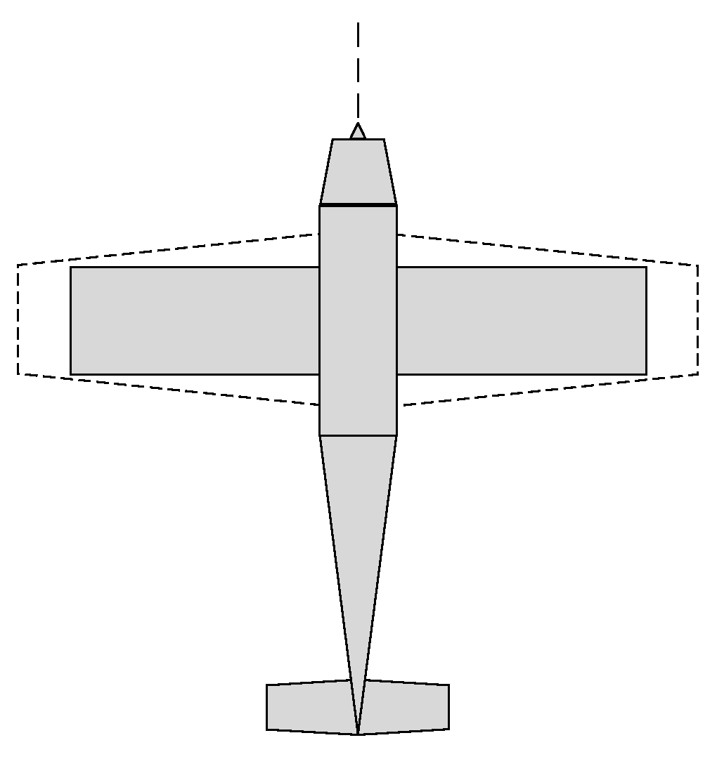
Figure 1. A concept design of shape-morphing wing in planform.
Aerospace 12 00125 g001
Figure 2. Shape-morphing wing in planform: (a) undeformed; (b) deformed.
Aerospace 12 00125 g002
Figure 3. Expected NPR maximum absolute value distribution of N blocks along spanwise direction.
Aerospace 12 00125 g003
Figure 4. A metamaterial cell with NPR: the BRATC cell.
Aerospace 12 00125 g004
Figure 5. Sensitivity of νxy against geometrical parameters: (a) νxy against ax; (b) νxy against ay; (c) νxy against θ; (d) νxy against φ.
Aerospace 12 00125 g005aAerospace 12 00125 g005b
Figure 6. Sensitivity of Ex against geometrical parameters: (a) Ex against ax; (b) Ex against ay; (c) Ex against θ; (d) Ex against φ.
Aerospace 12 00125 g006
Figure 7. Schematic diagram of BRATC cells’ distribution in wing planform.
Aerospace 12 00125 g007
Figure 8. Distributed spars in the wing.
Aerospace 12 00125 g008
Figure 9. Displacement loads and boundary constraints.
Aerospace 12 00125 g009
Figure 10. Pressure coefficient distribution diagram of the NACA0012 airfoil at 6.3° angle of attack.
Aerospace 12 00125 g010
Figure 11. Sample points of wing planform contour.
Aerospace 12 00125 g011
Figure 12. Comparison of shape-morphing wing: optimized contour vs. object contour.
Aerospace 12 00125 g012
Figure 13. Wing-shape contour error against iteration.
Aerospace 12 00125 g013
Figure 14. Contours of undeformed wing: (a) von Mises stress and Sxx; (b) displacements on z−axis.
Aerospace 12 00125 g014
Figure 15. Contours of deformed wing: (a) von Mises stress and Sxx; (b) displacements on z−axis.
Aerospace 12 00125 g015
Figure 16. Airfoils’ sample points in simulation: (a) section view at the axis of symmetry of the BRATC cell; (b) section view at the boundary of the BRATC cell.
Aerospace 12 00125 g016
Figure 17. Airfoils at the axis of the symmetry profile of the BRATC cell in simulation.
Aerospace 12 00125 g017
Figure 18. Airfoils at the boundary profile of the BRATC cell in simulation.
Aerospace 12 00125 g018
Figure 19. Comparison of shape-morphing wing at different Δchord values: (a) 20%; (b) 25%; (c) 30%.
Aerospace 12 00125 g019
Figure 20. Deformation experimental equipment of wing: (a) schematic diagram; (b) physical picture.
Aerospace 12 00125 g020
Figure 21. Comparison of shape-morphing wing in experiment: (a) undeformed; (b) deformed.
Aerospace 12 00125 g021
Figure 22. Comparison of shape-morphing wing between FEM and experiment.
Aerospace 12 00125 g022
Table 1. Initialized geometric parameters of BRATC cells.
NO.baxayθ/°φ/°
00.233900
10.233900
20.243900
30.243900
40.253804
50.253754
60.263700
70.263600
p.s.: R is 5 mm.
Table 2. Load 1 and boundary conditions.
Degree of FreedomFace AFace BFace C
UxDis_load00
Uy00Free
UzFree00
URxFree00
URyFree00
URzFree00
Table 3. Optimal geometric parameters of BRATC cells.
NO.baxayθ/°φ/°
00.233900
10.233900
20.243900
30.243900
40.253584.5
50.2535213.8
60.26349.87
70.263440.1
Table 4. Results of deformed wing at different target contours.
ΔspanΔchordArK
5%20%15.50%1.29%
5%25%18.13%1.40%
5%30%20.75%2.02%
Disclaimer/Publisher’s Note: The statements, opinions and data contained in all publications are solely those of the individual author(s) and contributor(s) and not of MDPI and/or the editor(s). MDPI and/or the editor(s) disclaim responsibility for any injury to people or property resulting from any ideas, methods, instructions or products referred to in the content.