Article

Divergence Evaluation Criteria for Lunar Departure Trajectories Under Bi-Circular Restricted Four-Body Problem

by
Kohei Takeda
1,* and
Toshinori Kuwahara
1,2,*
1
Department of Aerospace Engineering, Tohoku University, Sendai 980-8579, Japan
2
Research Center for Green X-Tech, Tohoku University, Sendai 980-8579, Japan
*
Authors to whom correspondence should be addressed.
Aerospace 2025, 12(10), 918; https://doi.org/10.3390/aerospace12100918
Submission received: 30 April 2025 / Revised: 29 September 2025 / Accepted: 30 September 2025 / Published: 12 October 2025

Abstract

This study focuses on the nonlinear departure dynamics of spacecraft from the Near Rectilinear Halo Orbit (NRHO) to the outer regions of Selenocentric Space. By carefully selecting the combination of orbital parameters and the order of the evaluation process, it becomes possible to precisely identify the divergence moment and to reliably classify the subsequent dynamical space. An empirical divergence detection algorithm is proposed by integrating multiple parameters derived from multi-body dynamical models, including gravitational potentials and related quantities. In an applied analysis using this method, it is found that the majority of perturbed trajectories diverge into the outer Earth–Moon Vicinity, while transfers into the inner Earth–Moon Vicinity are relatively limited. Furthermore, transfers to Heliocentric Space are found to be dependent not on the magnitude of the initial perturbation but on the geometric configuration of the Sun, Earth, and Moon during the transfer phase. The investigation of the Sun’s initial phase reveals a rotationally symmetric structure in the perturbation distribution within the Sun–Earth–Moon system, as well as localized conditions under which the destination space varies significantly depending on the initial state. Identifying the divergence moment allows for comparative evaluation of the spacecraft’s nonlinear dynamical state, providing valuable insights for the development of safe and efficient transfer strategies from selenocentric orbits, including those originating from the NRHO.

1. Introduction

As international lunar exploration activities are expected to intensify in the coming years, many researchers are actively engaged in studies related to the utilization of cislunar space. Notably, the Near Rectilinear Halo Orbits (NRHOs), a type of halo orbit located around the Earth–Moon Lagrange point two (EML2), are expected to serve as a launch base for many small satellites with the installation of the Lunar Orbital Platform Gateway (Gateway). This has led to active research and analysis of the characteristics and related dynamics of NRHOs [1,2,3]. The NRHO is one of the moderately stable cislunar periodic orbits that is not difficult to depart from or inject into, featuring an extremely elliptical trajectory with a maximum distance of 78,000 km from the Moon’s center compared to a minimum distance of 4000 km [4]. The change in velocity during the orbit is substantial, with a velocity difference of 1.527 km/s between the periapsis and apoapsis. Due to these characteristics, spacecraft departing from the NRHO exhibit chaotic motion, depending on conditions such as the departure position and the magnitude and direction of perturbation forces. After being given a perturbation, spacecraft departing from NRHO generally follow chaotic motion and either remain in the Selenocentric Space, transfer to the Earth–Moon-centered space (Geocentric Space), or transfer to the Heliocentric Space. This change in behavior is primarily caused by the spacecraft gaining or losing potential due to its relative motion with the Moon. Among these, the transfer to Heliocentric Space has been analyzed for its usability as a disposal orbit for decommissioned spacecraft or space debris [5].
The transfer to Geocentric Space is a particularly important phenomenon that deserves significant attention. From the perspective of disposal orbits, it is crucial to investigate the conditions under which objects may remain in the Earth–Moon space indefinitely, posing long-term risks. More importantly, the transfer or departure behavior to Geocentric Space has practical applications. Recently, the rise in the development of small-scale spacecraft under 100 kg and large-scale international activities for lunar space exploration has increased demand for low-cost exploration missions launched from cislunar space. The objectives are diverse, ranging from lunar orbits and landing to outer planet exploration, planetary defense [6], and spacecraft mooring at Lagrangian points for comet rendezvous missions [7,8]. Achieving these goals, it is necessary for spacecrafts to be controlled at a high technical level through meticulously planned operations and management.
In particular, due to their limited resources and performance, small spacecraft require more advanced planning and operation for communications, power management, and attitude-and-orbit control. Accordingly, propulsion and orbital-maneuvering technologies for small spacecraft are being matured through continuous operations in Low Earth Orbit (LEO) [9,10]. Particularly, deep-space guidance and navigation capabilities are critical and are under active development [11,12,13]. One of the most critical challenges is earning the mechanical energy to reach the destination. Historically, most missions have relied on planetary swing-by maneuvers for acceleration, and the same applies to lunar departures [14]. Strategies incorporating Earth and Moon swing-bys are crucial for ensuring mission extendability.
In this study, we focus on the lunar swing-by and the trajectory involving lunar departure and re-encounter for such maneuvers. The symmetric structure of the Earth–Moon dynamical system allows for various periodic motions synchronized with the Moon’s orbital motion [15]. By applying these periodic motions as trajectories for re-encounters from the Moon to the Moon, opportunities for lunar swing-bys can be achieved [16]. This transfer is generally referred to as the Moon-to-Moon Boomerang (M2MB) transfer, mimicking the returning behavior [17,18]. In designing M2MB, the spacecraft’s departure from the lunar sphere and re-encounter must be evaluated reliably. Since NRHO-originating trajectories develop into chaotic motion, the behavior during departure and reunion often includes unclear intermediate states. Thus, methods for estimating the spacecraft’s state and controlling it to ensure departure from the lunar sphere must be devised.
A fundamental approach to observing chaotic behavior is using Lyapunov exponents. This method evaluates the difference between a reference state and a perturbed state. Observing the eigenvalues of the state transition matrix derived from the equations of motion for nonlinear dynamics allows for numerical derivations of Lyapunov exponents. Previous studies, such as Cody et al. (2015) [19], investigated the application of Lyapunov exponents to spacecraft dynamics, organizing mathematical concepts and exploring effective maneuver strategies utilizing time-series predictions. Lagrangian Coherent Structures (LCS), a concept widely used in structural and fluid mechanics, has been applied in space mechanics for attitude and orbit estimation and strategy development. In NRHO applications, studies by Guzzetti et al. (2017) [20] and Muradilharan et al. (2022) [21] used the concept of LCS to define directions most and least likely to depart from NRHO. They evaluated trajectories departing in these directions and analyzed NRHO’s dynamic characteristics. However, the definition of “departure” in these studies relied solely on an eccentricity-based index when approximating the two-body problem with regard to the Moon, independent of LCS concepts. Boudad et al. (2022) [5] pointed out that this index alone makes the moment and location of departure uncertain, while safety directions were derived from departure epoch and state histories to departure; a more detailed discussion of “departure” is necessary as a premise. Alternative methods for defining departure, such as using a sphere of boundary (SOB) like the Hill sphere or sphere of influence (SOI), also exist. However, these methods are influenced by the boundary radius setting and fail to cover chaotic phenomena near the boundary, equivalent to issues with eccentricity-based evaluations. In summary, finding a systematical solution to these difficulties of evaluating chaotic departure behavior with a single parameter and threshold is the challenge of this study.
In addition to these previous studies, recent advances in multi-body dynamics and stability analysis have provided further insights into cislunar orbital behavior. For example, Oshima (2021) [22] and Oshima (2025) [23] investigated retrograde periodic and co-orbital trajectories under solar perturbations within the four-body framework, highlighting extended stability regions and transfer mechanisms. Zimovan et al. (2020) [24] analyzed the stability and resonance properties of NRHOs and nearby higher-period structures. Fu et al. (2025) [25] further applied the concept of LCS to low-energy Earth–Moon transfers with lunar ballistic capture. These works complement the existing body of research by demonstrating the relevance of multi-body effects and advanced stability techniques, thereby motivating the need for more reliable departure classification methods such as those addressed in this study.
This study aims to establish a precise method for determining spacecraft departure from NRHO by incorporating multiple parameters, thereby addressing challenges associated with departure assessment. This discussion constitutes the initial step in the strategic planning of M2MB transfers, specifically focusing on the departure from the cislunar region. In particular, functions related to the pseudo-potential and momentum of the four-body problem are utilized to propose and validate a classification algorithm for identifying the dynamical region in which the spacecraft resides. The proposed algorithm serves as a foundational framework for analyzing key departure characteristics, such as the time required for departure and the energy state at the moment of departure. Ultimately, this study contributes to the development of an optimized NRHO departure strategy that facilitates efficient transfers to M2MB trajectories.

2. Fundamental of Multi-Body Dynamics

In this study, two coordinate systems are defined. One is the circular restricted three-body problem (CR3BP) [26]. The celestial bodies handled are Earth and the Moon, and the behavior of spacecraft is expressed with a mass approximated to zero. The other is the bi-circular restricted four-body problem. The celestial bodies handled are the Sun, Earth, and Moon, and they all exist on the same plane. The behavior of spacecraft, which are also treated as micro-mass bodies, is expressed with a higher degree of fidelity than CR3BP. The two dynamical systems are often used as initial designs for orbital planning in the subsequent process of full ephemeris. In this chapter, we discuss the equations of motion and the definition of the phase angles of the Sun and Moon, which will be the key in the discussion that follows.

2.1. Circular Restricted Three-Body Problem

The restricted three-body problem (R3BP) is a dynamical system that describes the motion and position changes in a single micro-mass body P 3 as time passes in a space where two effective mass bodies P 1 , P 2 are moving in Keplerian motion [27,28]. When the center of mass of the two effective masses is defined as B 1 , the constrained dynamical system in which the two bodies move in a circular motion around B 1 on the same plane is called the circular restricted three-body problem (CR3BP). Now, if we define the state of a spacecraft as x ˜ = [ r ˜ , v ˜ ] = [ x ˜ , y ˜ , z ˜ , x ˜ ˙ , y ˜ ˙ , z ˜ ˙ ] T , the basic equations of motion for CR3BP are given by
x ˜ ¨ = 2 y ˜ ˙ + U * x ˜ y ˜ ¨ = 2 x ˜ ˙ + U * y ˜ z ˜ ¨ = U * z ˜ .
Here, U * is called the pseudo potential and is an important parameter that indicates the potential of the spacecraft in the main dynamical system. When the ratio of the masses of the two effective bodies P 1 , P 2 is set to be μ ˜ = M 1 M 1 + M 2 , U * is expressed as
U * = 1 2 ( x ˜ 2 + y ˜ 2 ) + 1 μ ˜ r ˜ 13 + μ ˜ r ˜ 23 .
Here, M 1 , M 2 ( M 1 > M 2 ) is the mass of the two bodies P i , P j , and r ˜ i j indicates the distance between them. Also, these distances can be expressed using the vectors r ˜ 1 , r ˜ 2 from the origin B 1 to the two effective masses and the spacecraft position vector r ˜ = r ˜ 3 as
r ˜ 13 = | r ˜ 3 r ˜ 1 | = ( x ˜ + μ ˜ ) 2 + y ˜ 2 + z ˜ 2 r ˜ 23 = | r ˜ 3 r ˜ 2 | = ( x ˜ 1 + μ ˜ ) 2 + y ˜ 2 + z ˜ 2 .
In CR3BP, each parameter exists as a dimensionless definition. The reference mass is the sum of the masses of the two effective masses P 1 , P 2 , the reference distance l ˜ is the distance between P 1 , P 2 , and the reference time τ ˜ is the time when P 1 , P 2 complete one revolution around B 1 . The angular velocity n ˜ EM of the rotating system is normalized by these dimensionless parameters, with the angular velocity set to 1. In this study, we will be dealing with CR3BP, which shows the behavior of a spacecraft with a small mass, P 3 , when the main celestial body P 1 is the Earth and the secondary celestial body P 2 is the Moon, as shown in Figure 1.

2.2. Bi-Circular Restricted Four-Body Problem

The Bi-Circular Restricted Four-Body Problem (BCR4BP) is a multi-body problem that is an extension of the CR3BP by adding a fourth body with effective mass that also performs Keplerian motion. In general, the additional mass body is a star (the Sun) in the three-body problem of a planet, the Moon and a spacecraft. BCR4BP is the dynamics of a small mass body ( P 3 ) showing the change in the motion and position of the object over time in a dynamical field in which a star ( P 4 ), planet ( P 1 ) and the Moon ( P 2 ) move in the same plane. The motion of the three effective masses can be divided into two parts: a rotational motion around the barycenter B 1 of P 1 and P 2 which is same as the CR3BP, and a rotational motion around the barycenter B 2 of P 4 and B 1 . In this study, we define BCR4BP with P 1 as the Earth, P 2 as the Moon, and P 4 as the Sun. In this case, in particular, the former rotating system is called the Earth–Moon rotating frame, and the latter rotating system is called the Sun- B 1 rotating frame. It is natural to discuss the motion of P 3 by dividing it into these two rotating systems, and from now on, we will discuss the motion equations and related variables in each system.

2.2.1. Earth–Moon Rotating Frame

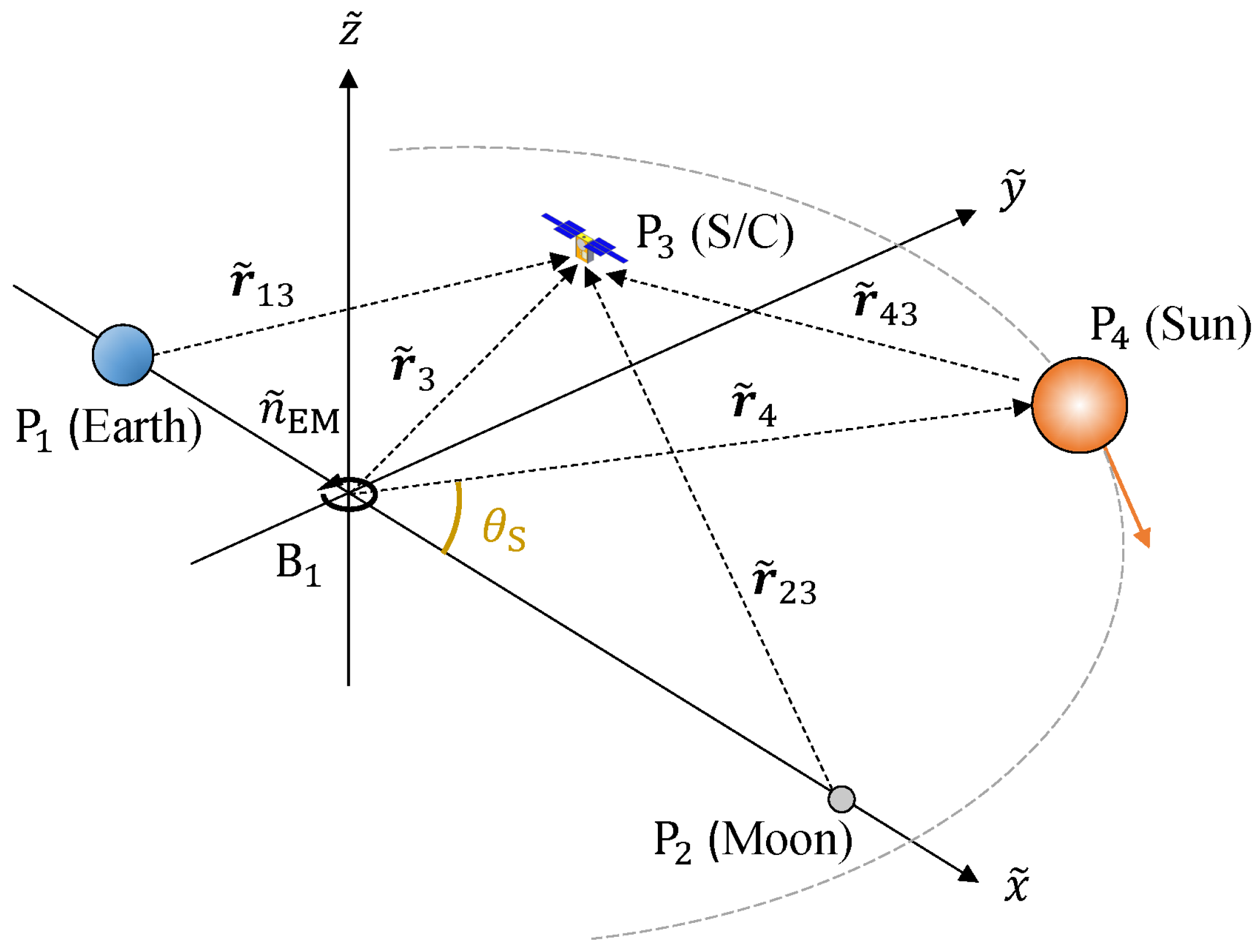
The Earth–Moon rotating frame is a system used in discussions of the mechanical structure and spacecraft behavior in the vicinity of the Moon or the Earth. Figure 2 shows the relationship between the Earth–Moon rotating frame and each celestial body. Basically, the coordinate axes of this rotating system are the same as those of the CR3BP, but the difference is that the Sun is moving in an independent circular motion around the common center of mass B 1 . Note that the Sun’s circular motion is clockwise, while the direction of rotation in this rotating system is counterclockwise. In other words, the angle between the x-axis of this system and the Sun vector, defined as the angle θ S , is taken counterclockwise as shown in the figure. Variables defined in this system are indicated with a tilde. Now, when the state of the spacecraft is defined as x ˜ = [ r ˜ , v ˜ ] = [ x ˜ , y ˜ , z ˜ , x ˜ ˙ , y ˜ ˙ , z ˜ ˙ ] T , the basic equations of motion of BCR4BP are given by
x ˜ ¨ = 2 y ˜ ˙ + Υ ˜ * x ˜ y ˜ ¨ = 2 x ˜ ˙ + Υ ˜ * y ˜ z ˜ ¨ = Υ ˜ * z ˜ .
Here, Υ ˜ * is called the pseudo potential of BCR4BP and is an important parameter that indicates the potential of spacecraft in this dynamical system. When the mass ratio of the two effective masses P 1 , P 2 discussed in CR3BP is set to be μ ˜ = M 1 M 1 + M 2 , the pseudo potential U * , defined in CR3BP, is used to express the pseudo potential Υ * as
Υ ˜ * = 1 2 ( x ˜ 2 + y ˜ 2 ) + 1 μ ˜ r ˜ 13 + μ ˜ r ˜ 23 + μ ˜ S r ˜ 43 μ ˜ S a S 2 ( x ˜ cos θ S + y ˜ sin θ S ) = U * + μ ˜ S r ˜ 43 μ ˜ S a S 2 ( x ˜ cos θ S + y ˜ sin θ S ) .
Here, μ ˜ S is the mass ratio of the Sun and the Earth–Moon system and is given by μ ˜ S = M 4 M 1 + M 2 . a S is the ratio of the distance between the Earth and the Moon, l ˜ , to the distance between the Sun and B 1 , l SB 1 , and is given by a S = l SB 1 / l ˜ . The distance between the Sun and the spacecraft, r ˜ 43 , is given by
r ˜ 43 = | r ˜ 3 r ˜ 4 | = ( x ˜ a S cos θ S ) 2 + ( y ˜ a S sin θ S ) 2 + z ˜ 2 .
When the spacecraft position does not change, the pseudo-potential U * in CR3BP is a time-invariant variable, but in BCR4BP, in addition to U * , there is a term that includes the time-varying solar phase, so that Υ ˜ * varies with time. As we will see in the next section, the Sun moves in a circular motion around B 1 , and since the angular velocity is constant at θ ˙ S , we can see that this time series change is periodic.

2.2.2. Sun- B 1 Rotating Frame

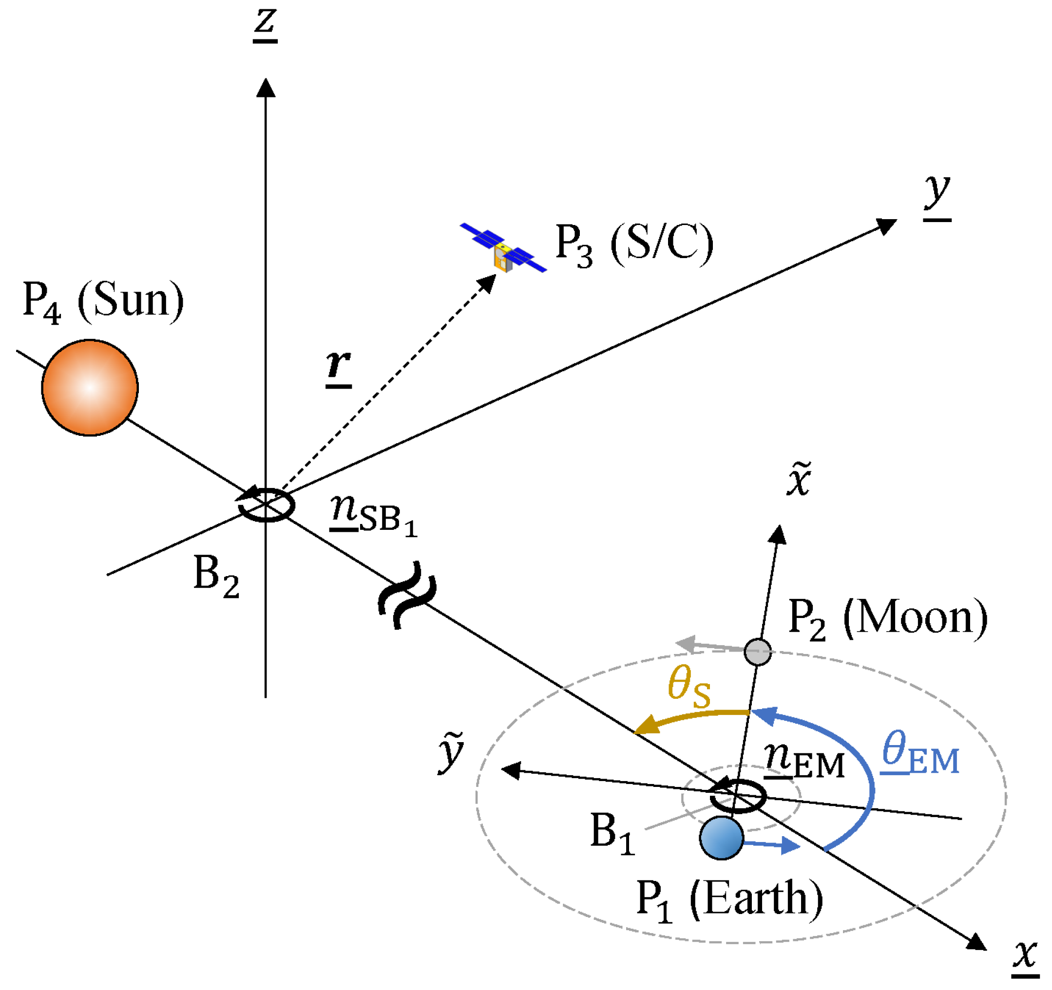
The Sun- B 1 rotating frame is a rotating system used to discuss the dynamics of the solar system, particularly in the vicinity of the Earth. Figure 3 shows the relationship between the Sun- B 1 rotating frame and each celestial body. The rotation center is the center of mass of the Earth–Moon system B 1 and the center of mass of the Sun–Earth system B 2 , and the Earth–Moon system is assumed to move circularly around B 2 in the same plane as the Sun. Variables defined in this system are underlined. Now, when the state of the spacecraft is defined as x ̲ = [ r ̲ , v ̲ ] = [ x ̲ , y ̲ , z ̲ , x ˙ ̲ , y ˙ ̲ , z ˙ ̲ ] T , the basic equations of motion for BCR4BP in this rotating system are given by
x ̲ ¨ = 2 y ̲ ˙ + Υ ̲ * x ̲ y ̲ ¨ = 2 x ̲ ˙ + Υ ̲ * y ̲ z ̲ ¨ = Υ ̲ * z ̲ .
Here, Υ ̲ * is the pseudo-potential of BCR4BP. When the mass ratio of the effective masses P 1 , P 2 for the entire system is set to μ ̲ = M 1 + M 2 M 1 + M 2 + M 4 , then Υ ̲ * is expressed as
Υ ̲ * = 1 2 ( x ̲ 2 + y ̲ 2 ) + μ ̲ ( 1 μ ˜ r ̲ 13 + μ ˜ r ̲ 23 + μ ˜ S r ̲ 43 ) ,
where r ̲ i j indicates the distance between two masses P i , P j and these distances can be expressed as follows using the vector from the origin B 2 to the Sun, r ̲ 4 , the spacecraft position vector, r ̲ = r ̲ 3 , and the vector between the two common centers of gravity, r ̲ B 2 B 1 .
r ̲ 13 = | r ̲ 3 ( r ̲ B 2 B 1 + r ̲ B 1 1 ) | = ( x ̲ 1 + μ ̲ μ ˜ a S cos θ ̲ EM ) 2 + ( y ̲ μ ˜ a S sin θ ̲ EM ) 2 + z ̲ 2 r ̲ 23 = | r ̲ 3 ( r ̲ B 2 B 1 + r ̲ B 1 2 ) | = ( x ̲ + μ ̲ μ ˜ a S cos θ ̲ EM ) 2 + ( y ̲ μ ˜ a S sin θ ̲ EM ) 2 + z ̲ 2 r ̲ 43 = | r ̲ 3 r ̲ 4 | = ( x ̲ μ ̲ ) 2 + y ̲ 2 + z ̲ 2 )
The phase angle, θ ̲ EM , is the angle between the Sun- B 1 rotating frame’s x-axis and the Earth–Moon rotating frame’s x-axis, and as shown in Figure 3, it is positive when moving counterclockwise. This is because the angular velocity of the Moon’s revolution is faster than that of the Earth’s revolution. Here, we can understand this by organizing the relationship between the angular velocity of each rotating system and the angular velocity of astronomical motion. As a preliminary to understanding, in BCR4BP, each parameter also exists as a dimensionless definition. The reference mass is the sum of the masses of the three effective masses P 1 , P 2 and P 4 , and the reference distance is the distance between B 1 and P 4 : l ̲ , and the reference time is the time when B 1 and P 4 complete one revolution around B 2 : τ ̲ . The dimensionless angular velocity is denoted by n and is expressed with a tilde or an underline depending on the apparent system. First, from Figure 3, the following relationship holds between the phase angles of the Earth–Moon axis: θ ̲ EM and the Sun: θ S in the Earth–Moon rotating frame.
θ ̲ EM = π θ S
Next, the angular velocity of the Sun- B 1 rotating frame, n ˜ SB 1 , is calculated as
n ˜ SB 1 = 1 + μ S a S 3 .
On the other hand, in the Earth–Moon rotating frame, the Sun is in circular motion around B 1 at constant angular velocity θ ˙ S , and this angular velocity can be calculated using the angular velocity of the system as
θ ˙ S = n ˜ SB 1 n ˜ EM = n ˜ SB 1 1 .
Since n ˜ SB 1 is approximately 0.0747, θ ˙ S takes a negative value. The reason for this is that, as we confirmed in the previous section, the direction of rotation of the Earth–Moon rotating frame is opposite to that of the Sun. From these parameters, the angular velocity of the Earth–Moon x-axis x ˜ in the Sun- B 1 rotating frame is shown as follows, paying attention to the sign of θ ˙ S :
θ ̲ ˙ EM = θ ˙ S × τ ̲ τ ˜ = τ ̲ τ ˜ ( 1 n ˜ SB 1 ) .
θ ˙ ̲ EM is the apparent angular velocity of the Earth–Moon axis as seen from the Sun- B 1 rotating frame and is an important parameter that characterizes the dynamical structure of the solar phase space. Table A1 of Appendix A shows the main parameters in the Earth–Moon rotating frame and the Sun- B 1 rotating frame, as well as the actual values used in this study.

2.3. Jacobi Integral, Hamiltonian and C 3

Here, we will discuss the potential defined by 2BP: C 3 , and the evaluation of spacecraft potential using the respective pseudo-potentials discussed in CR3BP: Jacobi integral and BCR4BP: Hamiltonian.

2.3.1. Jacobi Integral

One integral constant obtained from CR3BP’s equation of motion is similar to a conserved quantity of mechanical energy. This constant is called the Jacobi integral and is considered an important parameter that broadly indicates the mechanical behavior of spacecraft in CR3BP. The Jacobi integral is expressed by using the pseudo-potential in CR3BP U * as
C j = 2 U * v ˜ = 2 U * x ˜ ˙ 2 + y ˜ ˙ 2 + z ˜ ˙ 2 .
Since the second term represents the velocity of the spacecraft, when v ˜ = 0 , the Jacobi integral provides information about the region in which the spacecraft can move. This region, R 3 = { r ˜ : 2 U * C j } , is called the Hill sphere, and the 3D boundary where equality holds is referred to as the Zero Velocity Surface (ZVS) [29]. In CR3BP, the Jacobi integral remains constant, and for any initial value, a unique C j and ZVS are determined. Consequently, the ZVS can determine the potential locations within the Earth–Moon space where the spacecraft may reside, given its initial value. The ZVS ( C j value) allows for the distinction of three types of regions:
  • The space around the center of each celestial body (geocentric, selenocentric).
  • The space inside the Earth–Moon fusion region (E–M inner space).
  • The space outside the Earth–Moon fusion region (E–M outer space).
The boundary between these regions corresponds to the Earth–Moon Lagrange points. Specifically, when the Jacobi integrals at EML1 and EML2 are C j L 1 and C j L 2 , respectively, the former defines the boundary of the E–M inner space, and the latter defines the boundary of the E–M outer space. From the perspective of ZVS, EML1 and EML2 are called the L1-/L2-Gate. In this study, these two gates are used as key indicators for determining the direction of departure from the lunar region.

2.3.2. Hamiltonian

In BCR4BP, the Hamiltonian is used as a conserved quantity similar to mechanical energy. The Hamiltonian is a value that indicates the total energy of a system, as discussed in classical mechanics, and is generally defined as
H = i = 1 n p i q i L .
Here, p i , p j are the generalized coordinates and generalized momenta of the system, and L is the Lagrangian. In BCR4BP, since the number of effective mass bodies is three, expanding this equation for n = 3 results in the following representation:
H = 1 2 v 2 Υ ,
where the first term represents the velocity of the spacecraft. As discussed in the previous section, the BCR4BP has two rotating frame representations, and thus, the Hamiltonian also has two corresponding expressions. When the Hamiltonian value is taken negatively, as in H = 2 H , following the convention of the Jacobi integral, the Hamiltonian in each frame: H ˜ , H ̲ are defined as
H ˜ H ̲ = 2 Υ ˜ v ˜ 2 2 Υ ̲ v ̲ 2 ,
where Υ ˜ and Υ ̲ represent the pseudopotentials in BCR4BP. When the spacecraft’s velocity is set to zero, the Hamiltonian is equivalent to the pseudopotential. Focusing on the Earth–Moon Rotation Frame pseudopotential Υ ˜ , we see from Equation (17) that Υ ˜ and U * are identical except for the term arising from the solar tidal force. Unlike the time-invariant Jacobi integral, the Hamiltonian is a time-dependent variable due to the inclusion of the solar term. Note that in BCR4BP, the Sun undergoes circular motion, which makes this time dependence periodic.
The Hamiltonian is characterized by singular points at the positions of celestial bodies, where smaller values indicate higher dynamical conservation of the object. The closer an object is to a singular point, the greater the changes in its Hamiltonian value. Thus, the Hamiltonian can be used as an indicator for determining the passage of an object through specific spatial regions, similar to the role of the ZVS in the Jacobi integral. However, since the Hamiltonian is time-dependent, the Hamiltonian values at the L1-/L2-Gate also exhibit periodic variations over time. Consequently, the Hamiltonian does not represent an absolute boundary. This means it cannot guarantee that an object will remain permanently within a given spatial region but serves as a discrete indicator for determining the object’s current spatial location. In this study, the concepts of the Hamiltonian and the Gate, together with the Jacobi integral values, are applied to determine the direction of departure from the lunar region.

2.3.3. C 3

C 3 is defined in the two-body problem as the energy level of a spacecraft with respect to the central body. Unlike C j , this energy varies depending on the local state of the spacecraft in the inertial frame [30,31]. When considering the spacecraft’s velocity at infinity distance relative to the central body, referred to as the hyperbolic excess velocity ( v ), C 3 is generally defined as
C 3 = v 2 .
When evaluating C 3 in a rotating reference frame, the considering approach based on the perspective of mechanical energy is preferred. Given the velocity of a spacecraft at a distance r from central body P i , we can determine C 3 with the following relationship:
v = 2 m i r + v 2 .
Here, m i represents the gravitational constant of P i . In essence, C 3 is an indicator that evaluates the magnitude of the relative velocity of a spacecraft to the central body, with the potential value as a reference. By examining the sign of C 3 , it is possible to determine whether the spacecraft is in a state that can be approximated by the two-body problem. Generally, when C 3 is negative, the spacecraft is considered “captured” by the central body, and its motion can be described within the framework of the two-body problem. In this study, C 3 with respect to the Earth and the Moon is utilized as an indicator to evaluate whether the spacecraft has shifted to a state escaping from the vicinity of the Moon.

2.4. Momentum Integral

The moment integral (MI) is a geometric scalar quantity that represents the line integral of the position vector from a reference point over the time interval from t 0 to t. If the state vector of a spacecraft relative to the origin is defined as [ x , y , z , x ˙ , y ˙ , z ˙ ] , the MI from time t 0 to t is given by
MI ( t ) = t 0 t x ( τ ) x ˙ ( τ ) + y ( τ ) y ˙ ( τ ) + z ( τ ) z ˙ ( τ ) d τ .
The MI along a closed orbit corresponds to the circulation of the position vector in the observation system. This means that when the MI is calculated for a periodic orbit, it equals zero at the moment t = T , where T represents the time of one complete revolution. Utilizing this property, it is possible to observe the deviation of a perturbed orbit from its reference orbit. Let Γ ref denote the Momentum Integral profile of the reference orbit, and let Γ represent the Momentum Integral profile of the perturbed orbit deviating from the reference orbit. The hourly difference between these two profiles can then be expressed as
Δ MI ( t ) = log | MI Γ ( t ) MI Γ ref ( t ) | .
Perturbed orbits that deviate from a reference orbit typically transfer to non-periodic orbits after completing several cycles of orbital motion. From the perspective of Keplerian orbital mechanics, this transfer occurs when the osculating eccentricity exceeds 1, which signifies the transfer from an elliptical orbit to a hyperbolic orbit. Previous studies have shown that when the osculating eccentricity reaches 1, the corresponding value of Δ MI is approximately 0.1 [20]. Depending on the characteristics of the target orbit, the threshold for determining departure is generally set at either Δ MI = 0.1 or Δ MI = 0.2 . However, it should be noted that when Δ MI reaches these values, the orbit has typically already transferred to a non-periodic state. Consequently, the choice of threshold value is not critical for identifying the precise moment of departure but rather serves as an indicator of the transfer state. In this study, we adopt Δ MI = 0.1 as the standard threshold for determining departure following the precedent set by Boudad et al. [32].

3. Algorithms of Departure Evaluation

In this chapter, the foundational discussions are presented for analyzing spacecraft transfer trajectories from the lunar vicinity to four types of regions. First, the definitions of each region are clarified. Then, the method for determining the region in which the spacecraft resides is discussed. First of all, issues associated with existing algorithms that utilize a single parameter are presented together with the examples of classification flows based on previous studies, followed by a discussion of how the settings of the evaluation parameters affect the precision of the determination of divergence. Subsequently, the overall divergence evaluation flow suggested in this research is introduced, along with its underlying rationale. Finally, we address the existence of spacecraft behaviors that could not be identified using conventional algorithms and explain how these cases are handled in the suggested evaluation methods in this study.

3.1. Classification of Cislunar Space

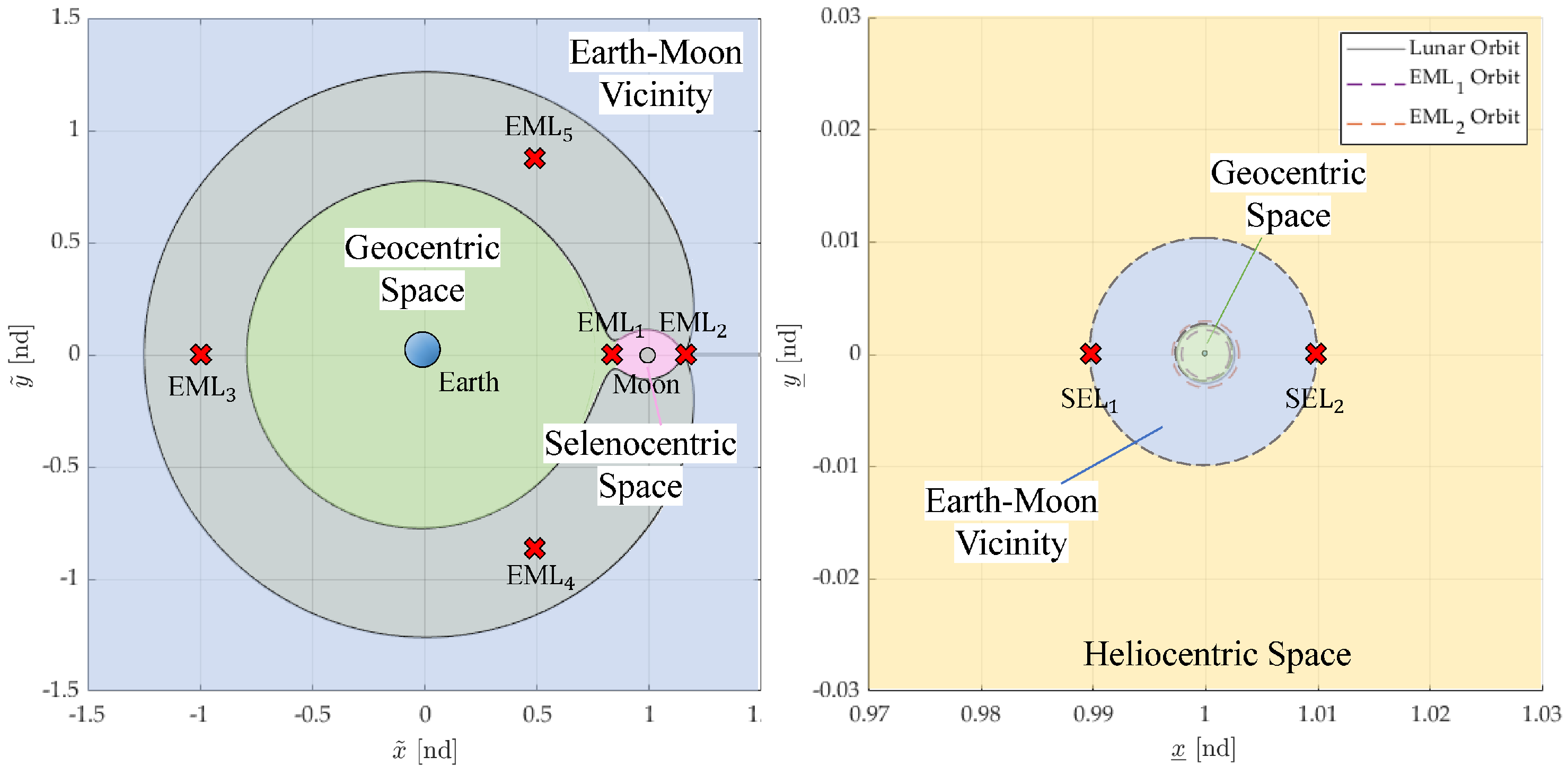
As the first step in this research, this section discusses the definition of the dynamical spaces in which spacecraft that have left the lunar sphere are located. Here, four spaces are defined based on the vicinity of the Moon where the Gateway is located. They are called “Selenocentric Space,” “Geocentric Space,” “Earth–Moon Vicinity,” and “Heliocentric Space” in this research. Figure 4 illustrates these four spaces. To aid understanding, note that the left figure represents the Earth–Moon rotating frame, while the right figure represents the Sun- B 1 rotating frame. The four spaces are defined equivalently in both frames. The curve in the left figure of Figure 4 represents the Zero Velocity Surface (ZVS), defined for a spacecraft with a Jacobi integral value of C j = C j L 2 . The gray-shaded area indicates a forbidden region, where spacecraft lack sufficient conserved energy to traverse when C j = C j L 2 . As explained in Section 2.3, the ZVS at C j = C j L 2 intersects the EML2 point (EML2-Gate), which acts as the boundary to distinctly separate the three spaces. The “Selenocentric Space” is defined as the area enclosed by the ZVS, the EML2-Gate, and the 2D plane with the same x-coordinate as the EML1 point. Depicted in pink in Figure 4, this region approximates the Hill sphere, which is often used as the lunar gravity sphere. The “Geocentric Space” is the area inside the ZVC excluding the “Selenocentric Space,” shown in green on the left of Figure 4. Here, it is defined as significantly smaller than the Earth’s Hill sphere, aimed at classifying Earth-centric orbits below the Moon’s orbital altitude. Periodic orbits with a period ratio to the Moon exceeding 1 traverse this region, often referred to as Earth-phasing orbits.
The “Earth–Moon Vicinity” (E–M Vicinity) is defined as the outer region beyond the ZVS and is represented in blue in both figures. The “Heliocentric Space,” shown in yellow, is defined as the region beyond the E–M Vicinity, where spacecraft and planets orbit around the barycenter of the Sun. A key aspect in distinguishing the E–M Vicinity from the Heliocentric Space lies in the dominance of solar tidal forces acting on spacecraft crossing the boundary and their resultant dynamical behavior. The region where the solar tidal force acts moderately is called as “Weak Stability Boundary (WSB),” whose definition and extent have been widely discussed by researchers such as Belbruno [33], representatively; while the rigorous formulation of the WSB is beyond the scope of this study, it is generally recognized that this region is roughly expanded around the spherical boundary that includes the Sun–Earth Lagrangian Points 1 (SEL1) and 2 (SEL2) on its surface. With a radius of approximately 3.5 × 10 7 km, this region is significantly larger than the Earth’s Hill sphere. Based on this background, the potential energies at SEL1 and SEL2 are introduced as evaluation criteria to distinguish the spacecraft’s dynamical region.
These four regions form the basis for discussions on orbital characteristics and their applications in this study. As explained in the next section, these regions where spacecraft reside are evaluated using a divergence evaluation algorithm based on the potential in the multi-body problem and the relative potential from the main celestial body.

3.2. Criteria of Divergence Instance

This section investigates the orbit divergence and its destination and discusses the method for determining the divergence. In Section 2.4, the MI and the indicator Δ MI , defined as the difference between the MI of the reference orbit and that of the perturbed orbit, are introduced as a method for quantifying the behavior of a perturbed orbit as it moves away from the reference orbit. However, there are two issues with these parameters. The first issue is the inability to evaluate the departure target. As mentioned in Section 2.4, MI is correlated with the contact eccentricity ratio with respect to the central body, but the change in MI does not provide information on the direction of departure or subsequent behavior. The second issue is the inability to detect departure in certain cases. This study aims to accurately determine the time of departure, so redundant evaluations of the departure time are not desired. Figure 5 illustrates an example of this phenomenon. The left two figures, plotted in a different rotating frame, show the perturbed orbit departing from the point on the 9:2 southern NRHO, and the right figure shows the time series of MI computed from these perturbed orbits. The perturbation conditions in this example are as follows: The true anomaly is 166.3 ° , the perturbation velocity is 5 m/s in the NRHO velocity direction, and the initial phase angle of the Earth–Moon axis is 180 ° . In this example, it can be confirmed that the orbit has left the NRHO and the vicinity of the Moon and has transferred to an elliptical orbit with the Earth as the central body. This behavior can be classified as a transfer to the E–M Vicinity. However, when looking at the time series data for Δ MI , it is impossible to determine the departure timing because the threshold value of 0.1 is never exceeded. By adjusting this threshold value downward, it may be possible to determine the timing in some cases, but this is not a fundamental solution because there is no certainty that it can be detected under other arbitrary perturbation conditions.
Boudad et al. (2022) [5] proposed a method for characterizing the trajectory of the transfer from NRHO to Heliocentric Space using the Hamiltonian of the Sun- B 1 system. This method relies on the Hamiltonian’s role in determining whether the SEL2-Gate opens or closes, and it sequentially searches for the spacecraft’s behavior as it leaves the system, identifying orbits that satisfy the three criteria set as candidates for transfer to Heliocentric Space: the moment integral, the Hamiltonian, and the effect of the solar tidal force. By combining these indicators, the algorithm of Boudad functioned as a simple and effective evaluation method to determine the destination of departure. However, because this method still relies on the Momentum Integral as a departure discriminator, it is subject to inherent inaccuracies in certain cases. In addition, this method cannot evaluate divergence toward the Geocentric Space. Therefore, it is unsuitable for accurately determining both the departure epoch and the final destination.
Therefore, we developed an alternative algorithm capable of accurately evaluating transfers not only to Heliocentric Space but also to the Geocentric Space and the E–M Vicinity. Figure 6 shows the departure evaluation algorithm developed in this study. The flowchart provides a sequential mechanism for evaluating each parameter, computed from the osculating orbital elements at discrete time steps. The colored boxes indicate the reachable regions and are shown with colors corresponding to the region definitions in Figure 4. The evaluation begins by checking whether the two-body energy with respect to the Moon, C 3 , M , is positive, and simultaneously verifying that the magnitude of the time derivative of the Hamiltonian is below a prescribed threshold. If both conditions are satisfied, the spacecraft is deemed to have diverged with respect to the Moon at that time.
This time derivative is the first-order time derivative of the Hamiltonian, H ̲ , defined in Equation (17), and is defined as follows [34,35]:
H ̲ ˙ = d H S B 1 d t = 2 μ ̲ ( 1 μ ˜ ) μ ̲ θ ˙ ̲ EM a S ( ( 1 μ ̲ x ̲ ) sin θ ̲ EM + y ̲ cos θ ̲ EM ) ( 1 r ̲ 23 3 1 r ̲ 13 3 ) .
The definitions of tilde and underline are as described in Section 2.2. This time derivative H ̲ ˙ provides information on the relative position of the spacecraft with respect to the central body. The boundary between the Geocentric Space and Selenocentric Space is defined by the EML1-Gateway. The equilibrium points near the collinear line that includes the EML1 point exhibit a saddle-like potential distribution centered at the equilibrium point. Notably, the EML1 point lies close to the Moon and is associated with the most significant change in potential [28]. To provide physical intuition, Table 1 presents the 10-day averaged Hamiltonian values at representative Lagrange points, illustrating the contrast between values in the Earth–Moon inner region and those in the outer region. It should be noted that the EML1 point lies in the Earth–Moon inner region, while the other three Lagrange points are located in the outer region. Previous work by Castelli et al. further confirmed that the acceleration-gradient field in the Sun- B 1 rotating coordinate system differs markedly between the interior and exterior of the Geocentric Space [36].
In principle, this allows evaluation of the spacecraft’s future motion, but there are some features to be aware of. H ̲ ˙ exhibits two characteristic behaviors: a micro-level behavior near a celestial body and a macro-level behavior farther away. At the micro level, when the spacecraft is near the celestial body, H ̲ shows significant variations. In the vicinity of the Moon, particularly along the NRHO where the velocity contrast between perilune and apolune is large, H ̲ shows large-amplitude, higher-frequency oscillations associated with the periodic motion. At the macro level, H ̲ undergoes a slow secular drift in the region where solar tidal forces gradually become effective, approximately 0.8 to 1.5 million km from Earth. This region corresponds to the WSB discussed in Section 3.1, where spacecraft can be accelerated or decelerated by the assist/resist effect of the solar tidal force. The magnitude of the secular drift in H ̲ due to the WSB is on the order of 10 1 per month, evolving over 1 to 3 months. Accordingly, based on these characteristics, we do not use H ̲ ˙ as a primary discriminator of the destination; instead, it serves as a guard criterion to avoid misclassifying early, near-NRHO asymptotic oscillations as departures.
To quantify an appropriate guard level, we performed a sensitivity analysis by sweeping the threshold H ̲ ˙ thr over several orders of magnitude (from 10 8 to 10 1 ) for three representative values of the initial perturbation Δ v dep . In this analysis, the ground truth was defined as the correct destination classification based on the regional partition in Figure 4, obtained by fixing the solar phase angle and sampling 3600 initial conditions in true anomaly on the NRHO. For each choice of H ̲ ˙ thr , the decision flow was applied, and its outputs were compared against this ground truth to evaluate the classification accuracy. The results show that the classification accuracy remains 100% for all thresholds H ̲ ˙ thr 6.0 × 10 6 , and the time-of-flight (ToF) to decision attains its minimum at H ̲ ˙ thr = 1.0 × 10 2 ; for larger thresholds, the ToF stays at this minimum. Based on this robustness, we adopt H ̲ ˙ thr = 1.0 × 10 2 as a default guard value in the present study, while noting that any choice 1.0 × 10 2 yields identical classification outcomes with the same minimal ToF. It should be emphasized, however, that excessively large thresholds would effectively disable the guard function, and thus values beyond the tested range were not considered applicable. A full sensitivity plot—misclassification rate on the left axis and ToF on the right axis for the three Δ v dep cases—is provided in Figure A1/Appendix B.
Figure 7 shows an example of the analysis, shown to contrast with the previous procedure. In this case, the true anomaly is 5.3 ° , the perturbation velocity Δ v dep is 7.7 m/s in the NRHO orbiting direction, and the initial phase angle of the Earth–Moon axis θ ̲ EM is 0.0 ° . The blue line indicates the time variation of Δ MI , while the orange line shows that of H ̲ ˙ . This example demonstrates that the departure judgment in the previous study was premature, since neither Δ MI nor H ̲ can clearly capture the transition to divergence. As discussed above, H ̲ exhibits alternating asymptotic and smooth behaviors in this case. The smooth portion around the crest of the curve, corresponding to the potential near apolune, lies outside the lunar SOI, where the spacecraft’s relative velocity to the Moon is small; under these conditions, H ̲ ˙ may fall below the threshold. Furthermore, if the spacecraft remains near the NRHO, or if it transfers to the Geocentric Space while preserving a similar z-direction periodicity, the osculating eccentricity may temporarily exceed unity, coinciding with the apolune-side behavior. This combined phenomenon can result in a false judgment that the spacecraft has exited the cislunar region, even though it remains dynamically within it, when using the previous procedure.
In our revised flowchart, divergence from the cislunar region is evaluated primarily by the energy-like parameter C 3 , M , while H ̲ ˙ serves only as a safeguard against false positives caused by near-NRHO oscillations. The subsequent classification of the final destination is then determined by C 3 , E . By eliminating dependence on the Momentum Integral, this mechanism avoids so-called “apolune-side departures,” even in cases where the osculating eccentricity temporarily exceeds unity while the motion remains dynamically akin to the NRHO family, as illustrated in Figure 7.

3.2.1. Departure to Geocentric Space

As mentioned in the previous section, when departing to the Geocentric Space, the spacecraft’s potential does not stabilize in the vicinity of the Earth; therefore, we begin with a guard step. Note that this step applies once a trajectory has been identified as a departure from the Selenocentric Space, i.e., when the two conditions C 3 , M > 0 and | H ̲ ˙ | H ̲ ˙ thr are satisfied. After this confirmation, the destination classification is performed solely by the spacecraft’s two-body energy with respect to the Earth, C 3 , E . Let C 3 , E M denote the Moon’s two-body energy with respect to the Earth; it is given by
C 3 , E M = v moon 2 2 μ r moon 1.03 [ s 2 / km 2 ] .
If C 3 , E C 3 , E M , the spacecraft is classified as having departed to the Geocentric Space.

3.2.2. Departure to Earth–Moon Vicinity

Following the same confirmation step, the case C 3 , E > C 3 , E M is classified as a transfer to the E–M Vicinity. This simplified rule avoids the “apolune-side” premature judgments: even when the osculating eccentricity temporarily exceeds unity and H ̲ exhibits a smooth segment near apolune—the segment highlighted by the green box in Figure 8—the Earth-relative energy does not surpass the lunar benchmark, and the trajectory remains within the cislunar space.

3.2.3. Departure to Heliocentric Space

The evaluation of transfers to Heliocentric Space is conducted after the classification to the E–M Vicinity. Consistent with prior work [5], we adopt a simple Hamiltonian-based check with respect to the Sun–Earth system: a heliocentric transfer is declared when H ̲ < H ̲ SE L 1 , 2 (see Table 1). A generalized, phase-space-level characterization (e.g., invariant manifolds or resonant structures) has been discussed extensively by Boudad et al. and lies beyond the scope of this study; we note it as future work.

4. Result: Time to Depart from NRHOs

Section 3 explained the definition of the region in the near-Earth–Moon space and the algorithm for determining the transfer to the region in detail. In this chapter, the empirical verification of the algorithm and the results are analyzed and discussed.

4.1. Calculation Environment

The numerical integration used in the trajectory calculations in this study was performed using the C++ boost library [37]. The Boost library is an open-source library containing many basic arithmetic algorithms written in C++, including numerical integration algorithms. In this study, we adopted the Runge–Kutta–Fehlberg 78 (RK78) method as the numerical integrator [38]. MATLAB® 2024a was adopted as the primary software, and the Boost library was executed using the MEX function of MATLAB [39,40].

4.2. Analysis 1: Empirical Validation of the Algorithm

As a first step in validating performance of the divergence-evaluation algorithm presented in Section 3, the orbit departure-classification flow was executed under the conditions listed in the Analysis 1 column of Table 2. The classification targets consist of two categories: Geocentric Space and E–M Vicinity. Each trajectory originates from one of 3,600 points along the 9:2 Southern NRHO, and numerical integration terminates upon evaluation of a divergence event, returning the final divergence state. Seven levels of initial departure velocity: Δ v dep were prepared (5–100 m/s). The initial phase angle of the Sun is fixed at zero for all simulations. The maximum propagation time was set to 200 days. Note that trajectories resulting in collision with the Moon or the Earth are regarded as invalid and excluded from the statistics. The guard threshold was set to H ̲ ˙ thr = 1.0 × 10 2 by default, which preserves 100% classification accuracy while attaining the minimal time to decision (see Section 3.2). In all simulations, numerical integrations use RK78 with relative and absolute tolerances set to 1.0 × 10 12 .
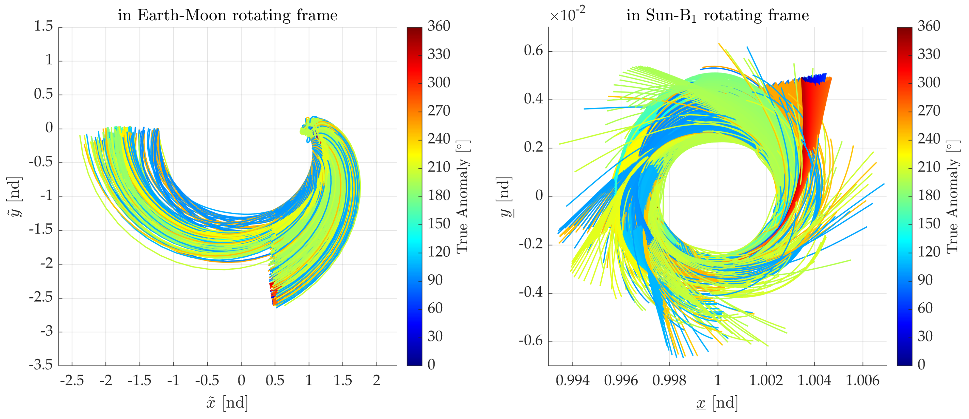
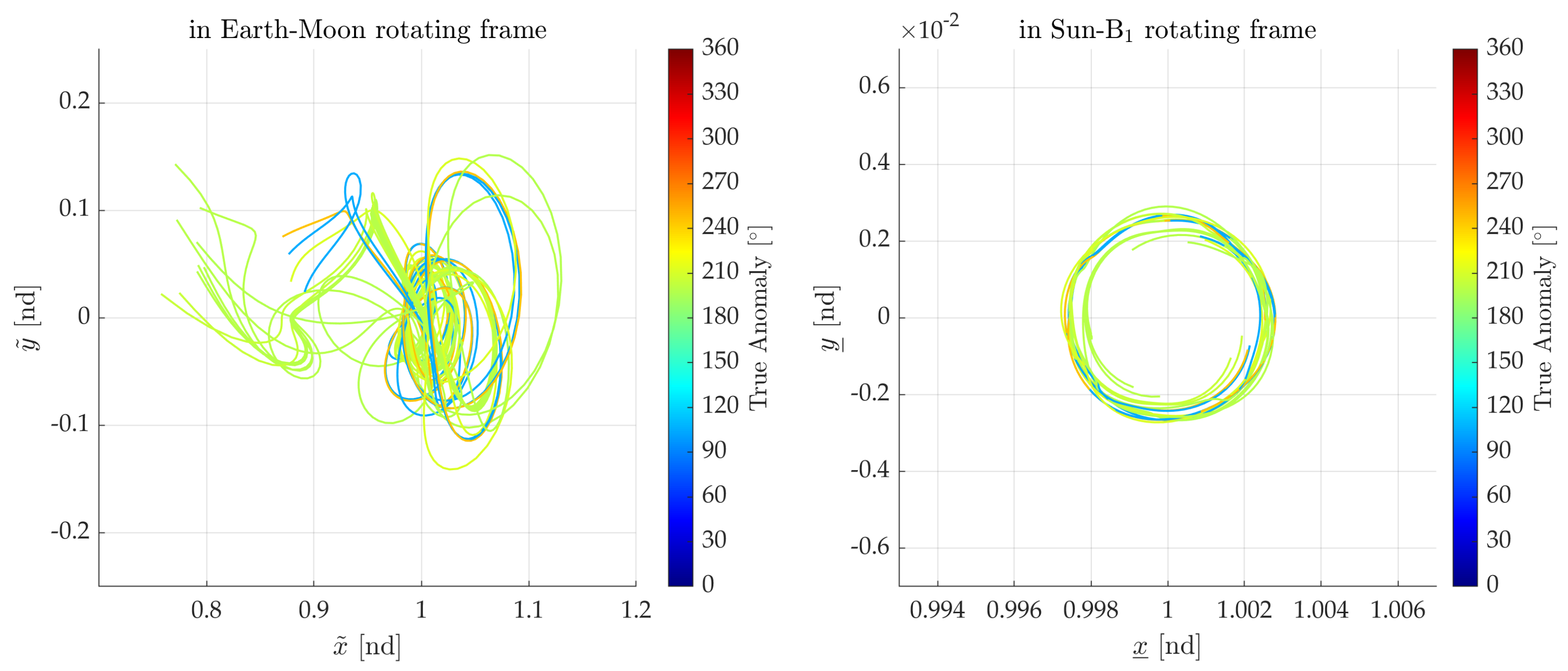
Table 3 summarizes, for each Δ v dep , the number of classified trajectories and the average time to the divergence decision. Figure 9 and Figure 10 display all trajectories from the departure points for the case Δ v dep = 5.0 m/s: Figure 9 shows transfers to the E–M Vicinity, whereas Figure 10 shows transfers to the Geocentric Space, demonstrating that the final destinations are classified as intended. In most cases, spacecraft reach the E–M Vicinity rather than the Geocentric Space; the number of geocentric transfers remains consistently small across all Δ v dep . The total number of trajectories classified as E–M Vicinity or Geocentric Space is less than 3600 (the total number of initial conditions) because many trajectories either collide with the Moon or the Earth or remain in the Selenocentric Space by the end of the 200-day horizon. Across all cases, more than 95% of the non-collision trajectories escape to the E–M Vicinity, with an average time to decision of roughly one to one-and-a-half months.
In addition, Table 2 presents the number of candidates transferring to Heliocentric Space that are flagged by the criterion ( H ̲ < H ̲ SE L 1 , 2 ), among trajectories classified as diverging toward the E–M Vicinity. For this representative configuration with the initial solar phase set to 0 ° , the times to flag vary substantially (approximately 34–91 days) and show no monotonic dependence on Δ v dep . This result supports the previous research from Boudad et al. [5] suggesting that, in determining divergence to the Heliocentric Space, the epoch of the perturbation plays a more crucial role than its magnitude or the departure location on the NRHO. In that prior study, it was observed that, regardless of the magnitude of the initial perturbation, spacecraft reaching WSB regions could acquire the potential required for a transfer to the Heliocentric Space, depending on their positional relationship with the three celestial bodies. Therefore, when planning Earth-return or M2MB transfer sequences that traverse the WSB region, it is critical to carefully consider the phase relationship among the celestial bodies to avoid unintended divergence to the Heliocentric Space. We expect similar tendencies under other initial solar-phase settings; however, a comprehensive assessment is beyond the scope of this study, and readers are referred to Boudad et al. [5] for detailed phase-space analyses.
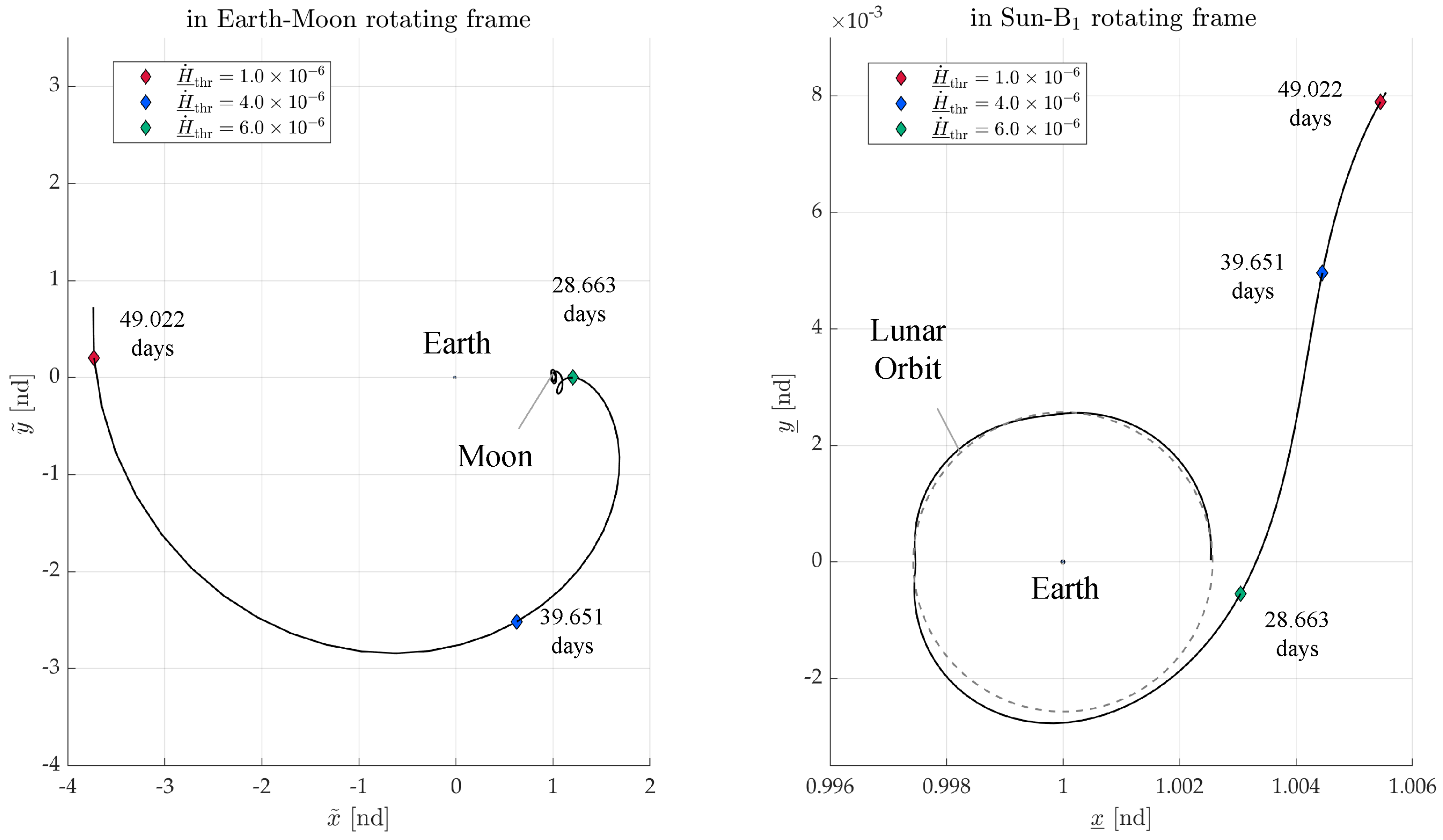
Next, we assess how the guard threshold H ̲ ˙ thr influences the decision timing and clarify its role in the overall logic. Figure 11 illustrates, for a representative initial condition, how stricter guard thresholds (e.g., 1.0 × 10 6 ) delay the divergence decision while leaving the final classification unchanged: the judgment time increases to 49.022 days—about 20 days longer than with the default setting—and intermediate values likewise produce intermediate delays. This behavior reflects the discrete sampling of the state and the nonuniform variation of H ̲ ˙ across initial conditions.
Although H ̲ ˙ admits a closed-form expression (Equation (22)), its direct physical significance as a destination discriminator is limited; accordingly, H ̲ ˙ thr is an empirically tuned parameter that should be adjusted to the computational environment. In our framework, the definitive condition that a trajectory has left the Selenocentric Space is C 3 , M > 0 , and H ̲ ˙ thr serves only as a protective filter to suppress early false positives and to select, among the discrete time samples that satisfy C 3 , M > 0 , the earliest instance at which the “diverged” flag is issued. In practice, H ̲ ˙ thr should be chosen to minimize the decision time without sacrificing correctness. Further refinements for pinpointing the exact divergence epoch and location are left for future work.

4.3. Analysis 2: Changes in Divergence Behavior Due to the Sun’s Phase Angle

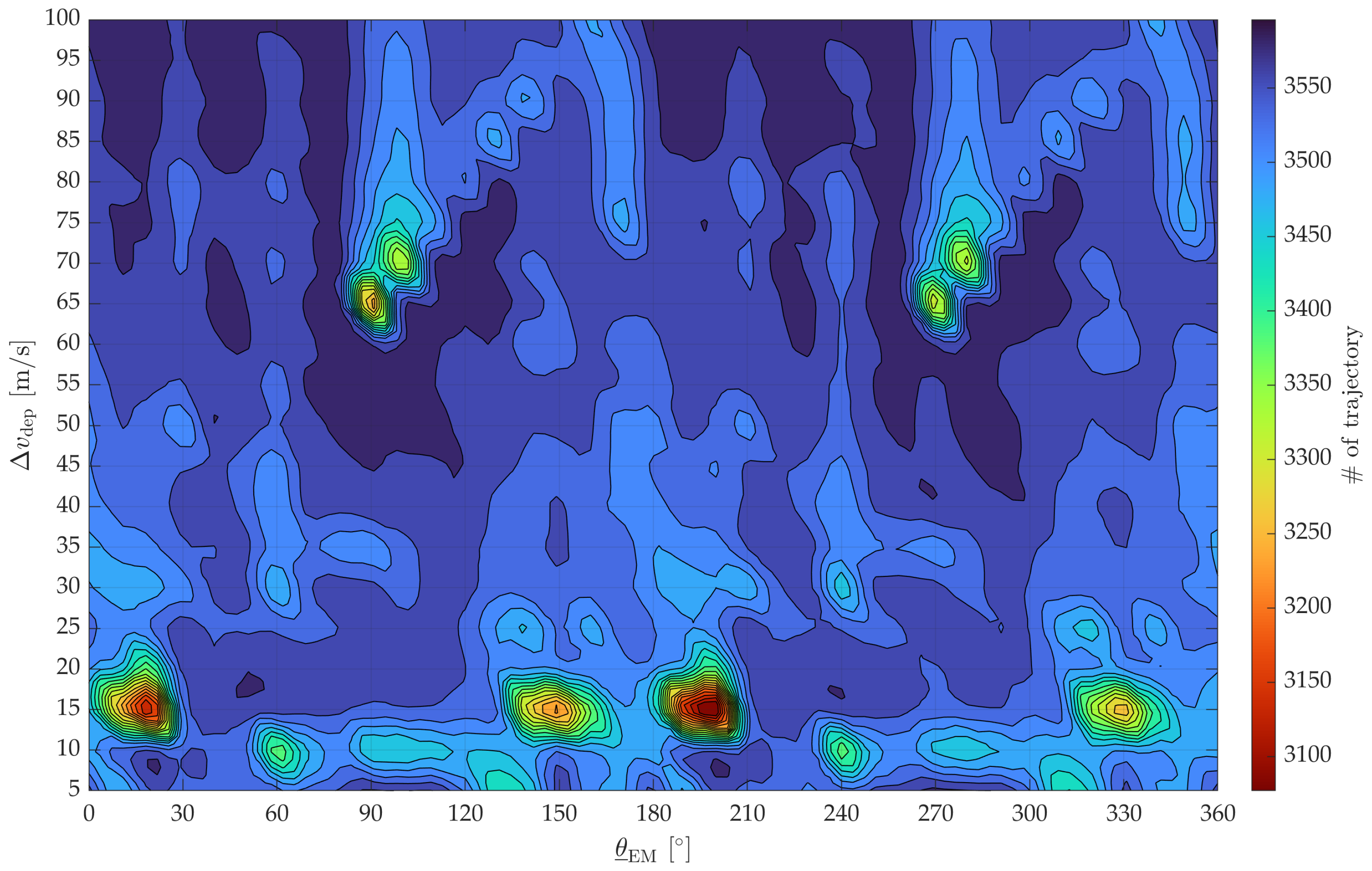
Next, we examined variations in departure behavior with respect to the phase angle of the Sun. The analysis was conducted under the conditions specified in the Analysis 2 column of Table 2. The dynamical model employed is the BCR4BP, and the analysis was performed over one full lunar cycle. This full-cycle analysis not only allows us to confirm that the classification algorithm consistently reflects the expected dynamical symmetry but also ensures that small deviations from perfect rotational symmetry, which arise from the solar gravity gradient in the BCR4BP tidal tensor, are properly taken into account. There are two primary methods for determining the NRHO departure position: one approach uses the Sun–Earth collinear line as the reference time, while the other uses the departure position as the reference time. In this study, we adopted the latter method to focus on the influence of the lunar departure phase. As in Section 4.2, we counted the number of orbits that transfer to either the Geocentric Space or the E–M Vicinity and also recorded collisions with the Earth or the Moon. The cases that either collide or do not satisfy the departure criteria within the propagation horizon constitute the remainder relative to the total of 3600. Figure 12 presents the number of trajectories that successfully transferred to the E–M Vicinity as a function of the Sun’s phase and departure velocity, Δ v dep . Regardless of the Sun’s phase or Δ v dep , a substantial number of cases reach the E–M Vicinity (i.e., the lunar far-side). At the same time, several localized phase-velocity conditions exhibit significantly lower trajectory counts. This suggests the existence of specific conditions under which escape to the far side is not achieved or where trajectories result in collisions with celestial bodies.
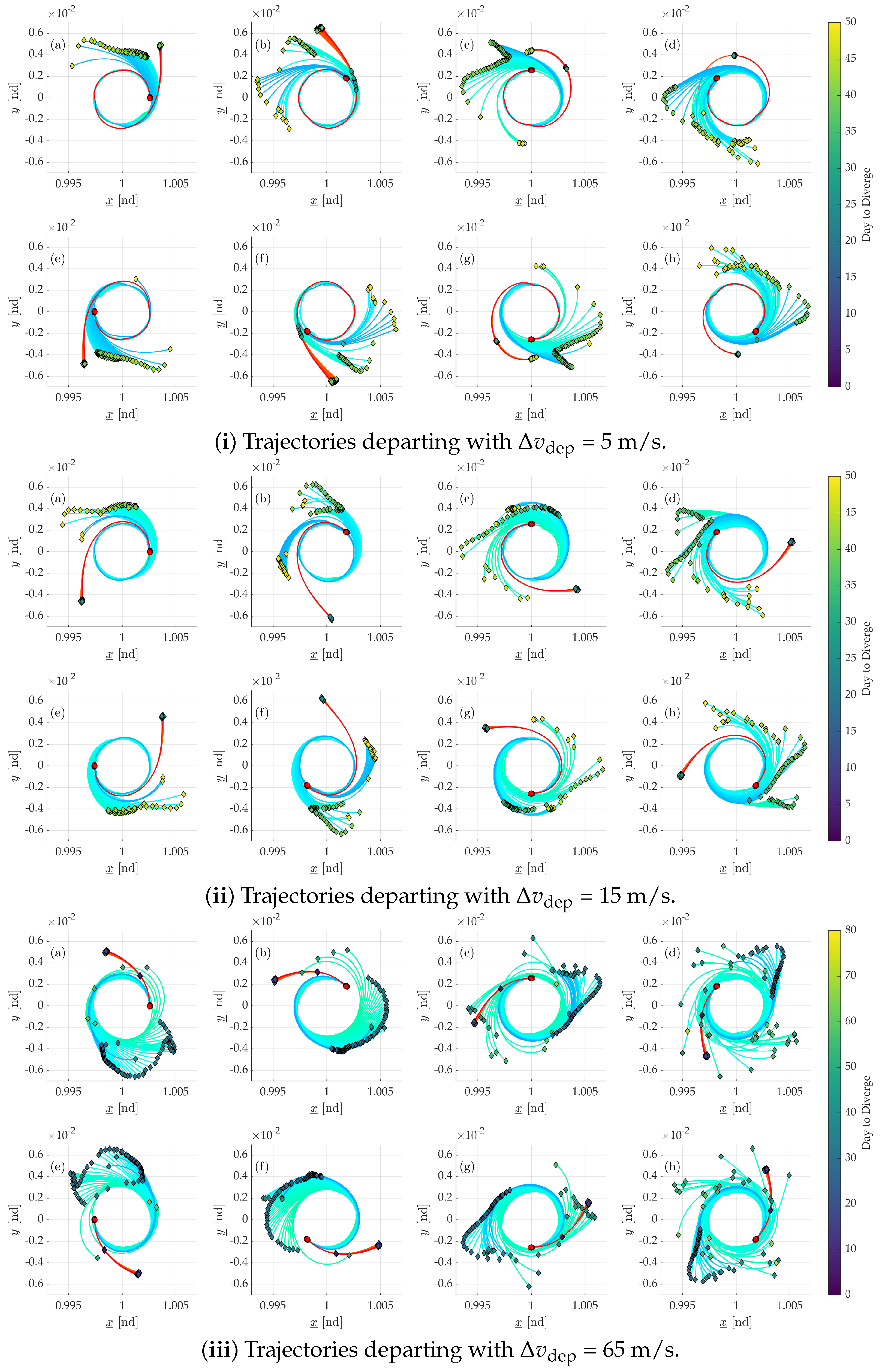
Additionally, this divergence distribution reveals that localized regions exhibit periodic and symmetric patterns at 180 ° . This phenomenon arises due to the symmetric nature of the tidal tensor field in the vicinity of the Earth–Moon system [41,42]. Figure 13 illustrates the divergent trajectories for eight representative cases of Sun’s phase: θ ̲ EM (in 45 ° steps) for three different values of Δ v dep (5, 15, and 65 m/s). For simplicity, these trajectories are limited to those that originate within a ± 20 ° range around the perilune and apolune. The departure points and the locations where departure is determined are marked accordingly. Each trajectory plot is arranged such that the upper and lower sections correspond to rotationally symmetrical conditions in θ ̲ EM . Consistently, the divergent trajectories and their corresponding judgment points are also found to be largely symmetrical. Furthermore, variations in departure behavior due to differences in the NRHO departure position can be observed. In each figure, the red trajectories originate near the NRHO perilune, while the blue trajectories originate near the NRHO apolune. These two trajectory families exhibit significant differences, underscoring the evident fact that the divergence behavior is influenced not only by Δ v dep and θ ̲ EM but also by the initial departure position.
The time to divergence exhibits substantial variability as a function of the initial perturbations and the Sun’s phase angle. The group of trajectories departing from the vicinity of the apolune exhibits a time difference of up to approximately 20 days until divergence. This suggests that departures initiated from the post-apolune region occur more rapidly than those from the pre-apolune region; while an increase in Δ v dep generally reduces the overall time to divergence, it also leads to decreased stability in departure behavior, as observed in Figure 13iii(c,g). In addition, when examining the locations where divergence is judged, it is evident that the dispersion of the judgment points increases with larger initial velocities. This phenomenon is attributed not only to the dynamical sensitivity (to θ ̲ EM and Δ v dep ) but also to algorithmic factors, notably the guard threshold on H ̲ ˙ and the discrete sampling cadence of the numerical data, which can introduce small delays in the issuance of the divergence flag. Consequently, apparent equivalence of judgment positions is more easily perturbed in accelerating states. These observations motivate refinements to minimize sensitivity to Δ v dep and θ ̲ EM —for example, by incorporating event-detection or adaptive time stepping around the expected divergence epoch—while retaining the current classification logic.

5. Conclusions

This study proposed a method for empirically determining the departure behavior of spacecraft from the NRHO and their subsequent transfer destinations. Through experimental analysis of departure behavior, it was confirmed that both the combination of orbital parameters and the order of the evaluation process are critical for precisely evaluating the timing of divergence and identifying the post-divergence dynamical space. A divergence evaluation algorithm was constructed using the time-series variations in gravitational potentials and related parameters in the two-body problem, the circular restricted three-body problem, and the bi-circular restricted four-body problem. Performance verification analyses demonstrated that the system can precisely evaluate the moment of divergence and reliably identify the destination space. However, the evaluation timing was found to be sensitive to algorithmic threshold settings, requiring adjustments according to the computational environment.
As an applied discussion, a comparative analysis was conducted under representative perturbation conditions to investigate the effect of the initial perturbations on divergence behavior. The results showed that a large number of perturbed trajectories diverged into the E–M Vicinity, while transfers to Geocentric Space were relatively limited. Furthermore, the transfers to Heliocentric Space were found to be dependent not on the perturbation magnitude at departure but rather on the geometric relationship between the Sun, Earth, and Moon during the transfer.
The effect of the Sun’s phase was also investigated. A distribution map illustrating the relationships among the Sun’s phase at NRHO departure, the perturbation magnitude, and the time to divergence revealed a rotationally symmetric structure of the gravity distribution in the Sun–Earth–Moon system, along with localized conditions under which transfers to the E–M Vicinity are significantly suppressed. Analysis focusing on the departure location relative to the Sun’s phase indicated that departures from the apolune region of the NRHO tend to exhibit divergence delays of approximately 20 days compared to those from the perilune region. Conversely, it was also confirmed that an increased velocity of trajectories can expand the time intervals of the discrete orbital data, potentially causing delays in the judgment process.
To further elucidate the factors governing departure behavior and destination space determination, improvements in the evaluation processes are essential. In addition, a more detailed analysis of the relationship between the potential acquired at departure and initial conditions on the NRHO is required. Furthermore, a more detailed phase space analysis incorporating invariant manifolds and resonant orbits will be an important direction for future research.

Author Contributions

Conceptualization, K.T. and T.K.; methodology, K.T.; software, K.T.; validation, T.K.; investigation, K.T.; resources, K.T.; writing—original draft preparation, K.T.; writing—review and editing, T.K.; visualization, K.T.; supervision, T.K.; project administration, T.K.; funding acquisition, T.K. All authors have read and agreed to the published version of the manuscript.

Funding

This research received no external funding.

Institutional Review Board Statement

Not applicable.

Informed Consent Statement

Not applicable.

Data Availability Statement

The data presented in this study are available on request from the corresponding author. The data are not publicly available as they are part of the first author’s ongoing doctoral research.

Conflicts of Interest

The authors declare no conflicts of interest.

Appendix A

The parameters within the coordinate system discussed in Section 2.1 and Section 2.2, and their respective definition formulas, are organized. All parameters were calculated based on the astronomical information library, DE431, published by NASA JPL [43].
Table A1. Principal parameters of the two coordinate: CR3BP and BCR4BP.
ParameterValueUnitDefinition
m Earth 3.9860 × 10 5 kg 3 · s 2 G × M Earth
m Moon 4.9028 × 10 3 kg 3 · s 2  [43]
m Sun 1.3271 × 10 11 kg 3 · s 2  [43]
l ˜ 3.8440 × 10 5 km [43]
l ̲ 1.4960 × 10 8 km [43]
τ ˜ 3.7519 × 10 5 s l ˜ 3 / m ˜  i
τ ̲ 5.0226 × 10 6 s l ̲ 3 / m ̲   ii
μ ˜ 1.0125- m Earth / m ˜
μ ̲ 3.0404 × 10 6 - m Earth / m ˜
θ ˙ S −0.9253-Equation (12)
θ ˙ ̲ EM 12.3869-Equation (13)
i  m ˜ = m Earth + m Moon . ii  m ̲ = m Earth + m Moon + m Sun .

Appendix B

This appendix summarizes the sensitivity of the guard threshold H ̲ ˙ thr . The initial solar phase was fixed at 0 ° . Along the 9:2 southern NRHO, 3600 departure points were sampled in true anomaly, and three representative perturbation levels were tested, Δ v dep { 5 , 10 , 15 } m / s . For each case, H ̲ ˙ thr was swept on a logarithmic grid from 10 8 to 10 1 . At every threshold, the classification flow was executed; the predicted destination (E–M Vicinity or Geocentric) was then compared against the truth labels defined by the regional partition in Figure 4 for the same initial conditions. From this comparison, we computed the misclassification rate and recorded the time-to-decision simultaneously. Figure A1 visualizes the results for the three Δ v dep cases. These curves support the settings adopted in the main text: accuracy saturates for H ̲ ˙ thr 6.0 × 10 6 , and the minimum decision time occurs at H ̲ ˙ thr = 1.0 × 10 2 .
Figure A1. Missjudgement rate (black, left axis) and average day of judgement (orange, right axis) versus guard threshold H ̲ ˙ thr (log scale). (a) Δ v dep = 5 m / s ; (b) Δ v dep = 10 m / s ; (c) Δ v dep = 15 m / s .
Aerospace 12 00918 g0a1

References

  1. Fuller, S.; Lehnhardt, E.; Zaid, C.; Halloran, K. Gateway program status and overview. J. Space Saf. Eng. 2022, 9, 625–628. [Google Scholar] [CrossRef]
  2. Williams, J.; Lee, D.E.; Whitley, R.J.; Bokelmann, K.A.; Davis, D.C.; Berry, C.F. Targeting Cislunar Near Rectilinear Halo Orbits for Human Space Exploration. In Proceedings of the AAS/AIAA Space Flight Mechanics Meeting, San Antonio, TX, USA, 5–9 February 2017. [Google Scholar]
  3. Boudad, K.K.; Howell, K.C.; Davis, D.C. Dynamics of synodic resonant near rectilinear halo orbits in the bicircular four-body problem. Adv. Space Res. 2020, 66, 2194–2214. [Google Scholar] [CrossRef]
  4. Howell, K.C.; Breakwell, J.V. Almost rectilinear halo orbits. Celest. Mech. 1984, 32, 29–52. [Google Scholar] [CrossRef]
  5. Boudad, K.K.; Howell, K.C.; Davis, D.C. Departure and Escape Dynamics from the Near Rectilinear Halo Orbits in the Earth-Moon-Sun System. J. Astronaut. Sci. 2022, 69, 1076–1114. [Google Scholar] [CrossRef]
  6. Annat, P.; Beal, C.; Verniere, J.; Felin, A.; Pinede, R.; Jaubeat, J.; Moussi, A. Hera Cubesats Trajectory Design and ConOps for Didymos Binary Asteroid Characterization. In Proceedings of the Small Satellite Conference, Utah State University, Logan, UT, USA, 1–3 August 2024. [Google Scholar]
  7. Tanaka, K.; Kawaguchi, J. Small-amplitude Periodic Orbit around Sun-Earth L1/L2 Controlled by Solar Radiation Pressure. Trans. JSASS Aerosp. Technol. Japan 2016, 59, 33–42. [Google Scholar] [CrossRef]
  8. Sánchez, J.P.; Morante, D.; Hermosin, P.; Ranuschio, D.; Eatalella, A.; Viera, D.; Centuori, S.; Jones, G.; Snodgrass, C.; Levasseur-Regourd, A.C.; et al. ESA F-Class Comet Interceptor: Trajectory design to intercept a yet-to-be-discovered comet. Acta Astronaut. 2021, 188, 265–277. [Google Scholar] [CrossRef]
  9. Saito, Y.; Kameyama, S.; Kuwahara, T. Simplified Data-Reduction Method for Hybrid Propulsion. J. Propuls. Power 2024, 40, 490–496. [Google Scholar] [CrossRef]
  10. Saito, T.; Kuwahara, T.; Saito, Y.; Sato, Y. Guidance strategies for controlled Earth reentry of small spacecraft in low Earth orbit. Acta Astronaut. 2025, 229, 684–697. [Google Scholar] [CrossRef]
  11. Komachi, S.; Fujita, S.; Takeda, K.; Nakaoka, H.; Kuwahara, T.; Yoshida, K.; Kawaguchi, J. Safe Attitude and Orbit Control for ISS-Deployed CubeSat HOKUSHIN-1 with Cold-Gas Propulsion System. In Proceedings of the 2024 IEEE/SICE International Symposium on System Integration (SII), Ha Long, Vietnam, 8–11 January 2024. [Google Scholar] [CrossRef]
  12. Kawaguchi, J.; Nada, Y.; Ishigooka, Y.; Kuwahara, T.; Yoshida, K. Asynchronous One-Way Range Measurement Applied to Microspace Probes. J. Spacecr. Rocket. 2022, 59, 1602–1612. [Google Scholar] [CrossRef]
  13. Kawaguchi, J.; Fujita, M.; Fujita, S.; Sakamoto, Y.; Kuwahara, T.; Yoshida, K.; Nishimoto, S.; Takeda, K.; Komachi, S.; Hayato, K. On the low-cost asynchronous one-way range measurement method and the device for micro to nano deep space probes. Acta Astronaut. 2024, 214, 457–465. [Google Scholar] [CrossRef]
  14. Oguri, K.; Oshima, K.; Campagnola, S.; Kakihara, K.; Ozaki, N.; Baresi, N.; Kawakatsu, Y.; Funase, R. EQUULEUS Trajectory Design. J. Astronaut. Sci. 2020, 67, 950–976. [Google Scholar] [CrossRef]
  15. Vaquero, M.; Howell, K.C. Leveraging Resonant-Orbit Manifolds to Design Transfers Between Libration-Point Orbits. J. Guid. Control. Dyn. 2014, 37, 1143–1157. [Google Scholar] [CrossRef]
  16. Nakazawa, K.; Takeda, K.; Komachi, S.; Fujita, S.; Kuwahara, T. Constructing Earth-Moon Data Relay System: Trajectory Design of Ballistic Lunar Transfer for Nano Spacecraft. In Proceedings of the 2023 IEEE/SICE International Symposium on System Integration (SII), Atlanta, GA, USA, 17–20 January 2023. [Google Scholar] [CrossRef]
  17. Farquhar, R.W. Utilization of Multi-Body Trajectories in the Sun-Earth-Moon System; NASA Technical Memorandum 80740; NASA Goddard Space Flight Center: Greenbelt, MD, USA, 1980. Available online: https://ntrs.nasa.gov/citations/19800022786 (accessed on 24 January 2025).
  18. Farquhar, R.W.; Dunham, D.W.; Hsu, S.C. Orbital acrobatics in the Sun-Earth-Moon system. In Proceedings of the International Symposium on Spacecraft Flight Dynamics, Toulouse, France, 20–23 December 1986. [Google Scholar]
  19. Short, C.R.; Blazevski, D.; Howell, K.C.; Haller, G.H. Stretching in phase space and applications in general nonautonomous multi-body problems. Celest. Mech. Dyn. Astron. 2015, 122, 213–238. [Google Scholar] [CrossRef]
  20. Guzzetti, D.; Zimovan, E.M.; Howell, K.C.; Davis, D.C. Stationkeeping Analysis for Spacecraft in Lunar Near Rectilinear Halo Orbits. In Proceedings of the Space Flight Mechanics Meeting, San Antonio, TX, USA, 5–9 February 2017. [Google Scholar]
  21. Muralidharan, V.; Howell, K.C. Stretching directions in cislunar space: Applications for departures and transfer design. Astrodynamics 2023, 7, 153–178. [Google Scholar] [CrossRef]
  22. Oshima, K. Retrograde co-orbital orbits in the Earth-Moon system: Planar stability region under solar gravitational perturbation. Astrophys. Space Sci. 2021, 366, 88. [Google Scholar] [CrossRef]
  23. Oshima, K. Extended analysis on stability, capture, and escape for planar retrograde periodic orbit around Earth. Astrophys. Space Sci. 2025, 370, 48. [Google Scholar] [CrossRef]
  24. Zimovan-Spreen, E.M.; Howell, K.C.; Davis, D.C. Near rectilinear halo orbits and nearby higher-period dynamical structures: Orbital stability and resonance properties. Celest. Mech. Dyn. Astron. 2020, 132, 28. [Google Scholar] [CrossRef]
  25. Fu, S.; Liang, Y.; Wu, D.; Gong, S. Low-energy Earth-Moon transfers with lunar ballistic capture based on Lagrangian coherent structures in a four-body model. Adv. Space Res. 2025, 75, 4993–5013. [Google Scholar] [CrossRef]
  26. Szebehely, V.; Grebenikov, E. Theory of Orbits, the Restricted Problem of Three Bodies; Academic Press: New York, NY, USA, 1967. [Google Scholar] [CrossRef]
  27. Howell, K.C. Three-dimensional, periodic, ‘halo’ orbits. Celest. Mech. 1984, 32, 53–71. [Google Scholar] [CrossRef]
  28. Koon, W.S.; Lo, M.W.; Marsden, J.E.; Ross, S.D. Dynamical Systems, the Three-Body Problem and Space Mission Design, 3rd ed.; Marsden Books: Wellington, New Zealand, 2011; pp. 24–41. [Google Scholar] [CrossRef]
  29. Meyer, K.R.; Offin, D.C. Introduction to Hamiltonian Dynamical Systems and the N-Body Problem, 3rd ed.; Springer International Publishing: Cham, Switzerland, 2017. [Google Scholar] [CrossRef]
  30. Yamakawa, H. On Earth-Moon Transfer Trajectory with Gravitational Capture. Ph.D. Dissertation, University of Tokyo, Tokyo, Japan, 1992; pp. 175–188. [Google Scholar]
  31. Curtis, H.D. Orbital Mechanics for Engineering Students, 4th ed.; Butterworth-Heinemann: Oxford, UK, 2020; pp. 93–98. [Google Scholar] [CrossRef]
  32. Boudad, K.K.; Davis, D.C.; Howell, K.C. Disposal Trajectories from Near Rectilinear Halo Orbits. In Proceedings of the AAS/AIAA Astrodynamics Specialist Conference, Snowbird, UT, USA, 19–23 August 2018. [Google Scholar]
  33. Belbruno, E.; Carrico, J. Calculation of weak stability boundary ballistic lunar transfer trajectories. In Proceedings of the AAS/AIAA Astrodynamics Specialist Conference, Denver, CO, USA, 14–17 August 2000. [Google Scholar] [CrossRef]
  34. Scheuerle, S.T.; Howell, K.C.; Davis, D.C. Energy-informed pathways: A fundamental approach to designing ballistic lunar transfers. Adv. Space Res. 2024, 75, 1096–1117. [Google Scholar] [CrossRef]
  35. Scheuerle, S.T. Low-Energy Lunar Transfers in the Bicircular Restricted Four-Body Problem. Ph.D. Dissertation, Purdue University, West Lafayette, IN, USA, 2024. [Google Scholar]
  36. Castelli, R. Regions of Prevalence in the Coupled Restricted Three-Body Problems Approximation. Commun. Nonlinear Sci. Numer. Simul. 2012, 17, 804–816. [Google Scholar] [CrossRef]
  37. Boost C++ Libraries. Boost 1.85.0 Library Documentation. Available online: https://www.boost.org/doc/libs/1_85_0 (accessed on 24 January 2025).
  38. Boost C++ Libraries. Class Template Runge Kutta fehlberg78. Available online: https://beta.boost.org/doc/libs/1_74_0/libs/numeric/odeint/doc/html/boost/numeric/odeint/runge_kutta_fehlberg78.html (accessed on 24 January 2025).
  39. The MathWorks, Inc. MATLAB Version: 24.1.0.2628055 (R2024a). Available online: https://www.mathworks.com/ (accessed on 24 January 2025).
  40. The MathWorks, Inc. MATLAB MEX File Functions. Available online: https://jp.mathworks.com/help/matlab/ref/mex.html (accessed on 24 January 2025).
  41. Takubo, Y.; Shimane, Y.; Ho, K. Optimization of Earth-Moon Low-Thrust-Enhanced Low-Energy Transfer. In Proceedings of the AAS/AIAA Astrodynamics Specialist Conference, Big Sky, MT, USA, 13–17 August 2023. [Google Scholar]
  42. Capuzzo-Dolcetta, R.; Giancotti, M. A study of low-energy transfer orbits to the Moon: Towards an operational optimization technique. Celest. Mech. Dyn. Astron. 2013, 115, 215–232. [Google Scholar] [CrossRef]
  43. Folkner, W.M.; Williams, J.G.; Boggs, D.H.; Park, R.S.; Kuchynka, P. The Planetary and Lunar Ephemerides DE430 and DE431. Interplanet. Netw. Prog. Rep. 2014, 42–196, 1–81. Available online: https://ipnpr.jpl.nasa.gov/progress_report/42-196/196C.pdf (accessed on 24 January 2025).
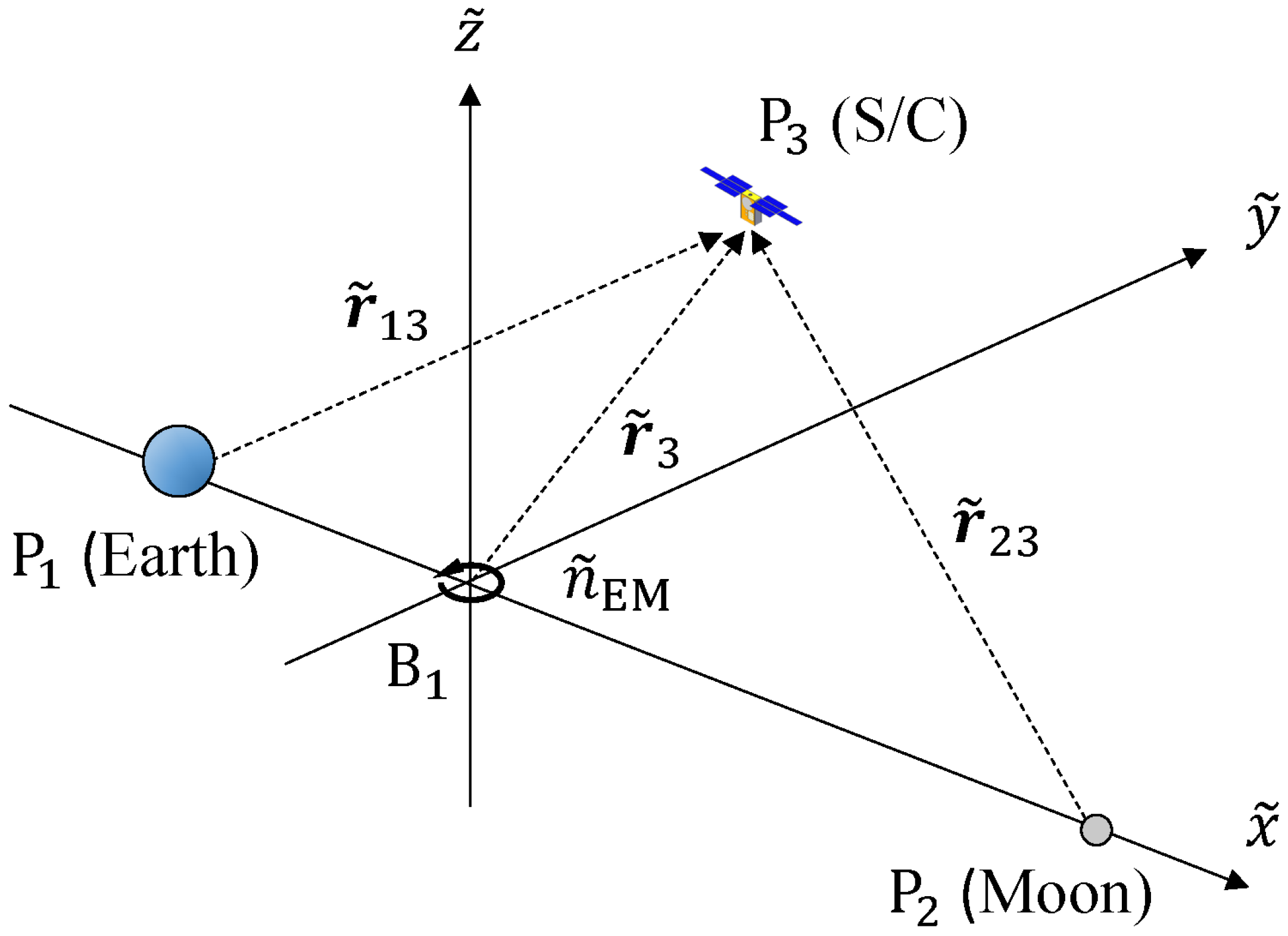
Figure 1. Flame of circular restricted three-body problem (CR3BP).
Aerospace 12 00918 g001
Figure 2. Coordinate of BCR4BP in Earth–Moon rotating frame.
Aerospace 12 00918 g002
Figure 3. Coordinate of BCR4BP in Sun- B 1 rotating frame.
Aerospace 12 00918 g003
Figure 4. (Left) Definition of Selenocentric Space, Geocentric Space and Earth–Moon Vicinity. (Right) Definition of Earth–Moon Vicinity and Heliocentric Space.
Aerospace 12 00918 g004
Figure 5. (Left,Middle) Example trajectory where divergence is not detected using only Δ MI . (Right) Time variation of Δ MI calculated from the example trajectory.
Aerospace 12 00918 g005
Figure 6. Flowchart of the divergence evaluation.
Aerospace 12 00918 g006
Figure 7. A case of possible misjudgment. The given perturbation is true anomaly = 5.3 ° , Δ v dep = 7.7 m/s, θ ̲ EM = 0.0 ° . The marker of the red diamond shows the evaluated point by the algorithm of Figure 6. The dotted lines indicate the reference values of the parameters labeled nearby. (Left) Time variation of Δ MI (blue, left axis) and H ̲ (orange, right axis). (Right) Trajectory in the Earth–Moon rotating frame, color-coded according to the existence regions defined in Figure 4.
Aerospace 12 00918 g007
Figure 8. A case of possible misjudgment of E–M Vicinity. The given perturbation is true anomaly = 22.8 ° , Δ v dep = 5.0 m/s, θ ̲ EM = 0.0 ° . If it is not limited to C 3 , M > 0 , the escape judgment is made at the point of about 18.75 days (green box). In other words, H ̲ ˙ and Δ MI alone cannot accurately determine the escape, and the position of judgment can be correctly evaluated by these parameters and checking C 3 with respect to the Moon C 3 , M . In this case, H EM L 2 > H , C 3 , M > 0 judges E–M Vicinity. In this case, C 3 , E > C 3 , E M judges E–M Vicinity.
Aerospace 12 00918 g008
Figure 9. Trajectories diverged to E–M Vicinity, colored with true anomaly at NRHO.
Aerospace 12 00918 g009
Figure 10. Trajectories diverged to Geocentric Space, colored with true anomaly at NRHO.
Aerospace 12 00918 g010
Figure 11. Judgment difference with related to the H ̲ ˙ threshold setting. The given perturbation is true anomaly = 65.1 ° , Δ v dep = 5 m/s, θ ̲ EM = 0.0 ° .
Aerospace 12 00918 g011
Figure 12. Distributions of the number of trajectories leaving the E–M Vicinity. Brighter colors indicate a lower number of transfers.
Aerospace 12 00918 g012
Figure 13. Trajectories departing to the Earth–Moon Vicinity with several Δ v dep at varied θ ̲ EM from 0 ° (top-left figure, a) to the 315 ° (bottom-right figure, h) in 45 ° steps. The trajectories are plotted for NRHO departures near-perilune (red) and near-apolune (blue). The red circle indicates the departure point, and the diamonds represent the days to divergence, color-coded by the color bar.
Aerospace 12 00918 g013
Table 1. Ten-day average of Hamiltonian H ̲ L N on each Lagrange point: L N in the Sun- B 1 rotating frame. The Hamiltonian on EML1 that exists only in Geocentric Space has a higher value than the other Hamiltonian for the other Lagrange points that exist in the E–M Vicinity.
Lagrange PointValue H ̲ L N
EML13.002236
EML23.000834
SEL13.000898
SEL23.000895
Table 2. Condition of the validation.
Analysis 1Analysis 2
PreferenceValue# of GridValue# of GridUnit
TA0.0 to 359.936000.0 to 359.93600 °
Δ v dep 5.0 to 100.075.0 to 100.020m/s
θ ̲ EM 0.0 (fixed)10.0 to 360.037 °
Table 3. Result of Analysis 1.
# of TrajectoriesAverage Day to Diverge
Δ v dep [m/s]E–M Vic.HeliocentricGeocentricE–M Vic.HeliocentricGeocentric
5.0356625901345.34858.55755.669
10.034982101644.47178.09562.582
15.034832833735.75343.28666.975
20.035082571334.17449.86359.159
25.035362305233.29672.91574.202
50.035262173125.52391.11651.392
100.029762590017.76133.969-
Disclaimer/Publisher’s Note: The statements, opinions and data contained in all publications are solely those of the individual author(s) and contributor(s) and not of MDPI and/or the editor(s). MDPI and/or the editor(s) disclaim responsibility for any injury to people or property resulting from any ideas, methods, instructions or products referred to in the content.