Abstract
To deal with the offense-defense confrontation problem of multi-missile cooperative intercepting a high-speed and large-maneuvering target, a differential game-based cooperative interception guidance law with collision avoidance is proposed, in which the offense-defense parties are the incoming target and the interceptors, respectively. Given that both offense-defense parties have uniformly decreasing speeds and first-order biproper dynamics, the relative motion models among the offense-defense parties are established, and the performance indices of the target and the interceptors are proposed. After that, the cooperative interception guidance law with collision avoidance is derived based on a differential game. The guidance law considers the effects of speed variations and rudder layouts on the motions of both offense-defense parties, ensuring excellent algorithmic real-time property and interception accuracy while introducing inter-missile collision avoidance constraints. In addition, the parameters of the target performance index are set according to the target acceleration information estimated by the interceptors. The simulation results verify the effectiveness of the guidance law designed in this paper, under various three-to-one scenarios, the interceptors could achieve collision-free interceptions with the interception accuracy of less than 5 m and the interception time difference of less than 0.1 s.
1. Introduction
Multi-missile cooperative interception has been a hot issue in the field of air defense in recent years. The main motivation is that the interception effect of a single missile is limited by its own performance, and it is difficult to cope with incoming targets with fast flight speed and high mobility [1]. Multi-missile cooperative interception breaks the traditional operation mode of single-missile independent operation, fuses multiple missiles into an integrated cluster with information sharing, functional complementation and tactical cooperation, and utilizes the cluster’s advantages to complete interception tasks that are difficult to accomplish with a single missile. As the key technology, the guidance design directly determines the interception effect of the missile swarm [2].
Multi-missile cooperative guidance is an important part of multi-agent cooperative control. However, compared with other agents such as unmanned aerial vehicles (UAVs) and unmanned ground vehicles (UGVs), missiles move faster and usually do not have abilities of speed control, which puts forward higher requirements for their guidance designs [3]. Specifically, for multi-missile cooperative interception, the guidance strategies aiming at high-speed and large-maneuvering targets are also different. For the former, the methods of multi-missile zoned interception, i.e., cooperative interception guidance laws based on coverage theory [4,5,6,7], are mainly adopted to make up for the lack of interceptors’ slow flight speeds. For the latter, the methods of multi-missile multi-directional interception, i.e., cooperative interception guidance laws with impact angle constraints [8,9,10], are mainly adopted to force the target to be unable to fully utilize its mobility. While the target has high-speed and large-maneuvering characteristics at the same time, it is necessary to design cooperative interception guidance laws based on differential games to carry out intelligent interceptions [11].
Differential games was proposed by Isaacs in the 1950s [12,13], and is mostly used to solve two-party dynamic confrontation problems. It combines game theory [14,15] and optimal control [16] to solve the optimal strategy that each party designs for itself in condition of the other taking optimal strategy, thus constituting the game equilibrium solution. Saridis [17] called the above process a “worst-case design.” Besides, differential games can also be used for optimal control of autonomous vehicle convoy [18], optimized power control in cognitive radio networks [19], and distributed energy trading for energy internet [20] and more.
In recent years, as the problem of multi-missile cooperative interception has received widespread attention, the research on differential games interception guidance law has gradually developed from one-to-one to many-to-one. Unfortunately, due to the more complex motion relations of cooperative interception, some motion characteristics of missiles considered in the context of one-to-one interception are simplified during the design processes of current differential games’ cooperative interception guidance laws [21,22,23,24,25]. For example, in the studies related to one-to-one interception, Refs. [26,27,28] describe the speed characteristics of missiles as variable-speed forms, and Ref. [29] approximates the dynamics of missiles in the first-order biproper form, taking into account the effect of rudder layouts, whereas Refs. [21,22,23,24,25] still adopt the constant-speed flight assumption and set missiles to have ideal or first-order inertial dynamics.
In addition, since both offense-defense parties cannot accurately know each other’s maneuvering intention, the complete information condition for studying differential games does not exist in the real confrontation process [30]. In fact, when designing a differential games interception guidance law, the defender always needs to rely on a certain degree of “imagination” to find the optimal strategy in some sense for intercepting a target that is not fully known. If the setting of a target is improper, the interception strategy designed based on that setting will almost certainly suffer some losses [31]. In this regard, it is necessary to investigate a feasible countermeasure.
Furthermore, for the problem of multi-missile cooperative interception, inter-missile collisions will cause the loss of operational power, which affects the success rate of interception, so it is necessary to consider collision avoidance when designing cooperative interception guidance laws based on differential games. The collision avoidance methods are mainly divided into three categories. The first one is to carry out path planning as shown in [32,33] to find the feasible path to reach the target point under the collision-free condition. However, its real-time property is poor because the path planning algorithms are generally computationally complex and cannot respond to the environmental changes quickly. The second such as [34,35,36,37] is to detect collisions during the guidance process, and take evasive measures when possible collisions are detected. Since the evasive measures are carried out after the detection, their effectiveness cannot be guaranteed, and they may cause guidance deviations. The third category as shown in [38,39,40,41,42] is to directly design guidance laws considering the collision avoidance, which simultaneously meets the requirements of algorithmic real-time property and guidance accuracy. Inspired by [42], this paper avoids inter-missile collisions by introducing an inter-missile distance constraint as the interior point constraint of optimal control.
Based on existing research, this paper proposes a differential game-based cooperative interception guidance law with collision avoidance. The main contributions are summarized as: (1) Establishment of a motion model of missiles with uniformly decreasing speeds and first-order biproper dynamics, which is more suitable for the real cooperative interception scenarios compared with the simplified models shown in [21,22,23,24,25] constant-speed flight and ideal or inertial dynamics are considered; (2) For the first time, the target acceleration information estimated by the interceptors is recommended to approximate the actual incoming target, avoiding the improper setting of target’s maneuvering intention; and (3) A inter-missile collision avoidance strategy is introduced in the design of cooperative interception guidance law based on differential games for the first time, which eliminates the potential inter-missile collision risks.
The rest of this paper is organized as follows: The problem studied in this paper is elaborated in Section 2 where the relative motion models of offense-defense confrontation and the guidance law design steps are established. The equilibrium solution of offense-defense confrontation game is solved in Section 3. The parameters of the target performance index are set in Section 4. Section 5 verifies the guidance effect of the guidance law designed in this paper through ballistic simulation. Section 6 concludes the work of this paper, and Section 7 presents the limitations of study and looks forward to future developments.
In the absence of special instructions, the symbol “(t)” used to indicate that the value of a variable is taken at the current moment, is omitted in this paper.
2. Problem Formulation
This paper investigates a differential game-based cooperative interception guidance law with collision avoidance, which applies to many operational scenarios of the key place air defense; for instance, the incoming target is a tactical ballistic missile attacking a specific ground building with preprogrammed maneuvers to increase penetration probability, and the defender launches multiple interceptor missiles expecting to achieve the terminal-phase interception of the target without inter-missile collisions.
The relative motion models of offense-defense confrontation and the guidance law design steps are established in this section based on the following assumptions.
- The lateral perturbations of offense-defense confrontation motion are negligible, and the longitudinal motion is independent of the lateral motion.
- Both offense-defense parties are considered as point masses and their rotations around center of mass are negligible.
- Both offense-defense parties are considered to have first-order biproper dynamics.
- Relative motions of offense-defense confrontation are linearized based on the small-perturbation method.
- The changes in flight speed of both offense-defense parties are approximated as uniform deceleration.
- The upper limits of normal available overload of both offense-defense parties are approximated as constants.
- The interceptors can infer the attack location of the incoming target.
- The interceptors can estimate the parameters related to dynamics characteristic of both offense-defense parties.
- The interceptors can obtain the position and velocity information of both offense-defense parties.
Assumptions 1–9 are briefly summarized as: (1) Assumptions 1 and 2 are common settings for designing longitudinal planar guidance laws of missiles; (2) The reasonableness of Assumption 3 would be analyzed in Proposition 1; (3) The applicability of Assumptions 4–6 is reduced in real flight environments, the impact of which would be discussed in Section 5; and (4) In Assumptions 7–9, the information required by the missile swarm could be provided from the guidance station.
2.1. Relative Motion Models
There are three kinds of relative motions concluded in the process of offense-defense confrontation, namely, the target-ground relative motion between the target and the ground building, the missile-target relative motion between each interceptor and the target, and the inter-missile relative motion between different interceptors.
The relative motion models established in this section are only used for the guidance law design.
Based on Assumptions 1 and 2, the motion relations of offense-defense confrontation are shown in Figure 1, in which the target is denoted as T, the ground building GB, the total number of effective cooperative interceptors n, the ith and the jth interceptors Mi and Mj, respectively, XOY is an inertial coordinate system with the ground building as origin, y, V, θ and a are the Y-direction coordinate, flight speed, ballistic inclination, and normal acceleration, respectively, RD the target-ground distance between the target and the ground building, Ri the missile-target distance between the ith interceptor and the target, Rij the inter-missile distance between the ith and the jth interceptors, and yD, yi and yij are the corresponding relative distances in the Y-direction, respectively.
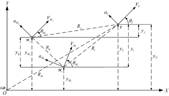
Figure 1.
The motion relations of offense-defense confrontation.
Remark 1.
There are two kinds of conditions such that the number of interceptors will be reduced during the offense-defense confrontation: one is that some interceptors lose the operational capability due to colliding with other interceptors; and the other is that some interceptors which fail to intercept are no longer involved in cooperative interception.
To establish the relative motion models of offense-defense confrontation, the composition of normal accelerations is analyzed and the reasonableness of Assumption 3 is elaborated. The details are described in the following proposition.
Proposition 1.
Both the offense and defense parties are missiles, and their normal accelerations are made up of
where aa is the normal acceleration generated by missile attitude changes due to rudder deflections, the response process of which is approximated in the inertial form, and ar is the normal acceleration generated by rudders themselves, the response process of which can be ignored.
Denote the guidance command as u, and express the relationships between aa and ar with u as
where l represents the direct lift coefficient satisfying 0 < |l| < 1 and is positive for canard control and negative for tail control, and τ the first-order time constant.
From Equations (1) and (2), the relationship between normal acceleration a with guidance command u is
Equation (3) is a first-order biproper form, showing that Assumption 3 is reasonable.
Next, according to the motion relations of offense-defense confrontation as shown in Figure 1, the three relative motions can be transformed to the Y-directions by defining the terminal moment and terminal distance in each relative motion, and then the three corresponding relative motion equations are derived based on Assumption 4. The details are described in the following proposition.
Proposition 2.
For the offense-defense confrontation, the target-ground, missile-target and inter-missile relative motion equations are established as follows.
(1) For the target-ground relative motion, the moment when the X-direction coordinates of the target and the ground building are the same is defined as the target’s attack moment, and is approximated as
the target-ground relative distance in the Y-direction at this moment is defined as the target’s attack miss distance and notated as .
The target-ground relative motion equation is
(2) For the missile-target relative motion, take the ith interceptor and the target as an example, the moment when X-direction coordinates of them are the same is defined as the ith interceptor’s interception moment, and is approximated as
the missile-target relative distance between the ith interceptor and the target in the Y-direction at this moment is defined as the ith interceptor’s interception miss distance and notated as .
The missile-target relative motion equation between the ith interceptor and the target is
(3) For the inter-missile relative motion, take the ith and the jth interceptors as an example, the moment when the X-direction coordinates of them are the same is defined as the approach moment of the ith and the jth interceptors, and is approximated as
the inter-missile relative distance between the ith and the jth interceptors in the Y-direction at this moment is defined as the approach distance of the ith and the jth interceptors and notated as .
The inter-missile relative motion equation between the ith and the jth interceptors is
The relative motion between the ith and the jth interceptors is studied only in case of a possible collision between them, the definitions related to collision would be given in Definition 2.
Based on Propositions 1 and 2, the following lemma is provided to establish the relative motion models of offense-defense confrontation.
Lemma 1.
For the offense-defense confrontation, the target-ground, missile-target, and inter-missile relative motion models are established as follows.
(1) The target-ground relative motion model is
where , , and are the state variable, control input, state coefficient matrix and control coefficient matrix, respectively, of the target-ground relative motion.
(2) The missile-target relative motion model is
where i denotes the index of an arbitrary interceptor, , , and are the state variable, control input, state coefficient matrix and control coefficient matrix, respectively, of the missile-target relative motion between the ith interceptor and the target.
(3) The inter-missile relative motion model is
where i and j denote the indices of arbitrary two interceptors, , , and are the state variable, control input, state coefficient matrix, and control coefficient matrix, respectively, of the inter-missile relative motion between the ith and the jth interceptors.
Remark 2.
Since the three relative motion models described by Equations (10)–(12) are relatively similar, the target-ground relative motion is taken as an example to illustrate the reason for selecting the normal acceleration generated by missile attitude changes as the state variable, while the remaining two relative motions will not be repeated.
From Equation (3), the derivative of the target’s normal acceleration with respect to time is
would be selected as a control input if is selected as the state variable of target-ground relative motion, which is unfavorable for the guidance law design. Therefore, the state variable shown in Equation (10) is selected to avoid the above problem.
To take full advantage of cooperative operation, the scenario in which multiple interceptors intercept the target at the same time is considered in this paper, and the interception moment of missile swarm is defined as follows.
Definition 1.
The interception moment of missile swarm is
and the interception moment is taken as tf uniformly for each interceptor.
Based on Lemma 1 and Definition 1, the following lemma is provided to establish the scalar relative motion models of offense-defense confrontation, where the proof of Equations (15)–(17) is detailed in Appendix A.
Lemma 2.
For the offense-defense confrontation, the target-ground, missile-target, and inter-missile relative motion models in scalar form are established as follows.
(1) The scalar target-ground relative motion model is
where is the target’s zero-effort attack miss distance, the state transition vector of from current to attack moment under zero-effort condition, and the target’s control coefficient function in the scalar target-ground relative motion model.
(2) The scalar missile-target relative motion model is
where is the ith interceptor’s zero-effort interception miss distance, the state transition vector of from current to interception moment under zero-effort condition, and and are the control coefficient functions of the ith interceptor and the target, respectively, in their scalar relative motion model.
(3) The scalar inter-missile relative motion model is
where is the zero-effort approach distance of the ith and the jth interceptors, the state transition vector of from current to approach moment under zero-effort condition, and and are the control coefficient functions of the ith and the jth interceptors respectively in their scalar relative motion model.
The scalar relative motion models shown in Lemma 2 are subsequently used to design the guidance law in this paper.
Finally, definitions related to collision are presented as follows to facilitate the study of inter-missile relative motions, and for the sake of simplicity, the possible collisions are directly called as collisions.
Definition 2.
Definitions related to collision are made as follows.
(1) The condition to determine a possible collision between the ith and the jth interceptors is
i.e., the motion tendency of the ith and the jth interceptors is close to each other and their approach moment is earlier than the interception moment of missile swarm.
(2) The collision between the ith and the jth interceptors is notated as
(3) The total number of inter-missile collisions is notated as c.
(4) All collisions are sorted in the ascending order of the first subscripts, if the first subscripts of some collisions are the same, these collisions are sorted in the ascending order of the second subscripts, which constitutes the following collision set:
where s denotes the index of an arbitrary collision, and the first and the second subscripts of the sth collision, respectively, both and can denote the sth collision. The collision set will vary with the tendency of inter-missile motions.
2.2. Guidance Law Design Steps
The differential game-based cooperative interception guidance law with collision avoidance would be designed in the following three steps.
First, establish game principles for the target and the interceptors where the parameters of the target performance index need to be set based on the target information obtained by the interceptors, and then the interceptors’ complete information condition is constructed by combining with Assumptions 7–9, i.e., the interceptors know the motion information and maneuvering intentions of both offense-defense parties.
Then, according to the offense-defense game principles, solve the game equilibrium solution by the idea of “worst-case design” of differential games, which is a combination of the target optimal penetration strategy and the interceptor optimal interception strategy, both derived on the condition that the other adopt its optimal maneuvering strategy.
Finally, analyze the expression of aforementioned target optimal penetration strategy, and replace the target’s guidance command with its acceleration information estimated by the interceptors to set the parameters of the target performance index.
The above design steps are described in detail as follows.
2.2.1. Establish Offense-Defense Game Principles
The terminal moment of game is taken as the interception moment of missile swarm shown in Equation (14), and the game principles of the target and the interceptors are established, respectively, as follows.
On one hand, it follows from the target’s maneuvering intention that the target penetration strategy expects to attack the ground building, escape from the interception, and reduce the energy consumption. As a result, based on Proposition 2, the performance index of the target is set as
where and are the zero-effort attack miss distance of the target and the zero-effort interception miss distance of the ith interceptor at the terminal moment, the target’s guidance command, , and are positive weight coefficients corresponding to attacking the ground building, escaping from the interception, and reducing the energy consumption, respectively, and their detailed values are shown in Equations (36) and (43).
On the other hand, the interceptors expect to successfully intercept the incoming target and avoid inter-missile collisions, and thus, the constraints on the interception strategy are proposed to be zero interception miss distance of each interceptor and enough inter-missile distance more than the safety distance between each pair of interceptors, which are called the interception constraint and collision avoidance constraint, respectively. Based on Proposition 2, the two constraints are denoted as
where r is the safety inter-missile distance. The setting of collision avoidance constraint is useful in eliminating inter-missile collision risks of multi-missile cooperative interception.
In addition, to reduce the total energy consumption of the missile swarm, the following performance index of the interceptors is set.
where is the ith interceptor’s guidance command, is the corresponding positive weight coefficient, and the weight coefficient for an interceptor with higher energy consumption should be set higher. Considering that the energy consumption of an interceptor is positively correlated with its remaining flight time and overload capacity, it follows from Assumption 6 that the value of should be set as
where is the upper limit of normal acceleration of the ith interceptor.
Equation (21) and Equations (22)–(24) are the game principles of the target and the interceptors, respectively.
2.2.2. Solve Game Equilibrium Solution
According to the idea of differential games “worst-case design”, the game equilibrium solution is solved by the following steps: first, derive the optimal maneuvering strategies of the target and the interceptors based on the classical variational method, and then, design the methods of taking values of and to calculate the above strategies, where defined in Equation (A20) is the vector of actual interception miss distances, and defined in Equation (A42) is the vector of approach distances required by collision avoidance constraint. The final obtained game equilibrium solution notated as satisfies
where , and denote the target optimal penetration strategy and the interceptor optimal interception strategy, and denote non-optimal strategies of the target, and the interceptors, is the augmented performance index of the interceptors introducing the interception and collision avoidance constraints presented in Equation (22) into the original performance index shown in Equation (23) whose explicit expression would be shown in Equation (30).
The above will be described in detail in Section 3.
2.2.3. Set Parameters of the Target Performance Index
If the setting of the target’s maneuvering intention is close enough to the real target, it can be considered that the cooperative interception guidance law designed on this basis can achieve the expected guidance effect.
Therefore, the parameters of the target performance index are set based on the target acceleration information estimated by the interceptors in this paper, such that the optimal penetration strategy satisfies
where is the target acceleration information estimated by all interceptors’ measurements of the target.
The interceptors’ cooperative interception guidance law is derived from the above setting, and the design details are shown in Section 4.
3. Derivation of Game Equilibrium Solution
After establishing the relative motion models of offense-defense confrontation and the guidance law design steps, the game equilibrium solution will be derived and discussed in this section to obtain the main result of this paper as follows.
Theorem 1.
The game equilibrium solution of both offense-defense parties is
where , , and are defined in Equation (21), in Equation (15), , and in Equation (A20), and in Equations (15) and (16), , and in Equation (A30), in Equation (A45), in Equation (A36) and in Equation (34).
Proof.
The procedures on how to derive the game equilibrium solution are carried out in four steps, firstly, derive the target optimal penetration strategy, then derive the interceptor optimal interception strategy, and discuss the methods of taking values of and , respectively.
Step 1: Derive the target optimal penetration strategy
Denote k as the kth interceptor for any k in . Recall the state equations and performance index related to the target optimal control problem described in Lemma 2 and Equation (21), which are
Based on the classical variational method, the target optimal penetration strategy is
where and are parameters related to the motion characteristics of the target and defined in Equation (A20), the derivation of which is detailed in Appendix B. In Equation (29), is the vector of actual interception miss distances associated with strategies of both parties, and the method of taking its value will be explained in Step 3.
Step 2: Derive the interceptor optimal interception strategy
Denote k as the kth interceptor for any k in , s as the sth collision as defined in Definition 2. Recall the state equations and performance index related to the interceptor optimal control problem described in Lemma 2 and Equation (23), which are
The augmented performance index of the interceptors is
where denotes the interception constraint on the kth interceptor, the collision avoidance constraint between the ith and the jth interceptors, and are the corresponding Lagrange multipliers. and are expressed as
Equation (31) is set based on Equation (22). In Equation (31), the interception constraint is a terminal constraint, and the collision avoidance constraint is an interior point constraint. Moreover, the terminal state of an inter-missile relative motion is negligible when its collision avoidance constraint is satisfied.
Based on the classical variational method [31], the interceptor optimal interception strategy is
where , and are matrices consist of control coefficient functions of the missile-target and inter-missile relative motions and defined in Equation (A30), and are function vectors related to the interception and collision avoidance constraints and defined in Equation (A36) and Equation (A42), respectively, is a matrix used to calculate the Lagrange multipliers and defined in Equation (A45).
The detailed derivation on how to get Equation (32) is given in Appendix C. In Equation (32), is a function vector associated with , the vector of actual interception miss distances, the method of taking whose value will be explained in Step 3, and is a function vector associated with , the vector of approach distances required by collision avoidance constraint, the method of taking whose value will be derived in Step 4.
Step 3: Predict the value of
Under the unconstrained control condition, the interceptors adopting the interception strategy (32) derived based on the classical variational method can realize the interception constraint presented in Equation (22), that is, the interception miss distance of each interceptor in the missile swarm is zero.
However, in the real process of offense-defense confrontation, upper limits exist on normal available overloads for interceptors, and thus the interception strategy shown in Equation (32) is often unattainable. Accordingly, the interception miss distance of each interceptor is not necessarily zero, so the value of , the vector of actual interception miss distances, needs to be predicted.
It is worth noting that the prediction of can be omitted for the cooperative interception guidance law design by ingenious setting of the target as described in Section 4, which could reduce the guidance law complexity.
Step 4: Optimize the value of
To reduce the total energy consumption of the missile swarm to a lower extent, an optimization method of taking the value of is proposed, and the optimal value is shown the following proposition, which is detailed in Appendix D.
Proposition 3.
The optimal value of is
where is the sth component of , is defined in Equation (A48). Replacing with, in Equation (32) is rewritten as
where is defined in Equation (A42).
Combining the above four steps, the game equilibrium solution of both offense-defense parties is obtained as shown in Theorem 1.
The proof is thus completed. □
4. Parameter Settings of the Target Performance Index
The application condition of differential games is that the set target can approximate the actual maneuvering target. In this section, the parameters of the target performance index are set based on the target acceleration information estimated by the interceptors. Subsequently, according to Theorem 1, the differential game-based cooperative interception guidance law with collision avoidance for the interceptors is derived as follows.
Theorem 2.
The differential game-based cooperative interception guidance law with collision avoidance is
where is defined in Equation (45).
Proof.
Theorem 1 shows that the calculation of the game equilibrium solution needs the ratio of to , and the ratio of to , where , and are weight coefficients of the target performance index.
(1) For setting
Considering that the proportional navigation guidance (PNG) is a classical guidance law used to attack stationary targets and is suitable for the incoming target expected to attack ground buildings in this paper, the following approximation is taken according to the design condition of PNG.
Remark 3.
If the target is not concerned with escaping from interceptions, Equation (27) would be rewritten as follows based on the constant-speed flight and ideal dynamics assumptions.
where is the target’s axial drag acceleration.
Substituting Equation (36) into Equation (37) yields
where and are the target-ground approach speed and line-of-sight angular rate, which is PNG.
It follows from Equation (36) that the game equilibrium solution of both offense-defense parties in Theorem 1 can be further expressed as
where
with and being defined in Equation (A34), , and in Equation (A36), and are parameters related to the motion characteristics of the target.
(2) For setting
The analysis of Equations (39)–(41) shows that the prediction of can be omitted by directly setting the whole value of when calculating the interceptor optimal interception strategy. In this paper, the target acceleration information estimated by the interceptors is considered the optimal penetration strategy adopted by the target, i.e.,
then it is obtained from Equations (39) and (42) that
Substituting Equation (43) into Equation (41), the interceptor optimal interception strategy shown as Equation (40) is rewritten as
where
The interceptors can estimate the target acceleration by filtering the measurement information of the incoming target. On this basis, the target adopting the optimal penetration strategy (42) can approximate the actual maneuvering target. Consequentially, the optimal interception strategy obtained in Equation (44) is the interceptors’ differential game-based cooperative interception guidance law with collision avoidance designed in this paper.
The proof is completed. □
Eventually, considering the upper limit of normal acceleration, the guidance command and normal acceleration of the ith interceptor are obtained as
where is the ith component of the proposed guidance law .
5. Results and Discussion
According to the engineering experience, when the miss distance is less than 5 m, the interceptor warhead can cause effective damage to the target and its interception is considered successful; and when the distance between two interceptors is less than 3 m, they can be considered to have collided.
This paper verifies the effectiveness of the proposed guidance law (44) through the ballistic simulations under a three-to-one scenario, where the three interceptors are homogeneous missiles with similar initial motion states, the motion and relative motion models of offense-defense confrontation are established as the real nonlinear motion systems, and the simulation parameters are listed in Table 1.

Table 1.
Simulation parameters.
5.1. Ideal Flight Environment
Based on a relatively ideal flight environment, Section 5.1 shows the realization of guidance law design intentions and compare it to PNG, the most classical homing guidance law in engineering applications, to demonstrate its superiority.
The ballistic simulation conditions are set as: (1) Ignoring the filtering error of the target acceleration information; (2) As stated in Assumption 5, the axial drag accelerations of offense-defense parties are both constants listed in Table 1; and (3) As stated in Assumption 6, the upper limits of normal acceleration of offense-defense parties are both constants listed in Table 1, which represent the structural limitations of the missiles.
The penetration strategy for the actual maneuvering target is set as a combination of generalized PNG and preprogrammed jumping maneuver, whose specific form is
where , , , and are the approach speed, line-of-sight angle and line-of-sight angular rate of the actual target to the ground building, respectively, , , and are the upper limit of normal acceleration, preprogrammed command, guidance command, and normal acceleration of the actual target, respectively.
Figure 2 shows the ballistic trajectories of the three interceptors and the target, and Figure 3 shows the inter-missile distances. It can be observed from Figure 2 that the miss distances of the three interceptors are all less than 5 m at 8.248 s, implying effectively cooperative interception. Moreover, Figure 3 shows that the nearest inter-missile distance is more than 3 m, which means no collision occurred in the interception.
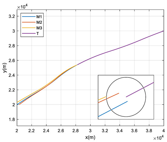
Figure 2.
Ballistics trajectories.
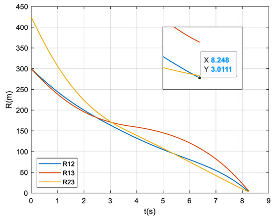
Figure 3.
Inter-missile distances.
Figure 4 and Figure 5 show the ballistic trajectories and the inter-missile distances without collision avoidance ( m) respectively. The figures demonstrate that interceptors 1 and 3 collide at 8.157 s, while interceptor 2 intercepts the target with a miss distance of 14.724 m.
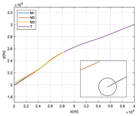
Figure 4.
Ballistics trajectories without collision avoidance.
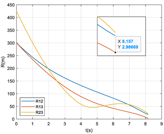
Figure 5.
Inter-missile distances without collision avoidance.
Figure 6 shows the ballistic trajectories of both offense-defense parties with all interceptors using PNG, the interceptors 1 and 3 collide at 8.027 s, and the interceptor 2 fails to intercept the target with a miss distance of 96.057 m.
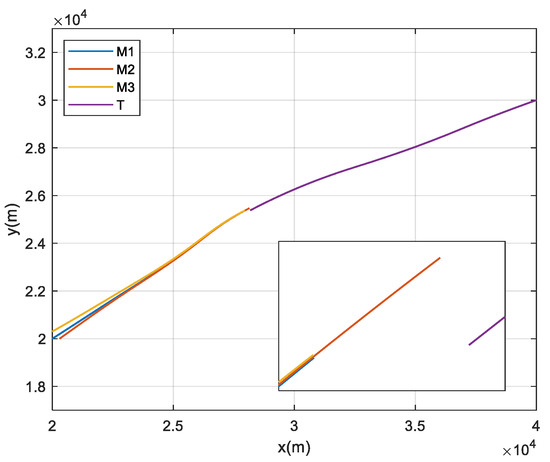
Figure 6.
Ballistics trajectories with PNG.
The above simulation results show that the proposed guidance law can successfully intercept the target while eliminating inter-missile collision risks under the condition that (1) the interceptor speeds are lower than the target and, (2) there are no obvious advantages in overload capacity. However, if the three interceptors use PNG individually, collision is difficult to avoid, and since the interceptors do not have significant performance advantages over the target, the interception effect is poor.
5.2. Complex Flight Environment
The applicability of Assumptions 4–6 presented in Section 2 is reduced in real flight environments. In addition, the guidance information errors will affect interception accuracy. To verify the effectiveness of the proposed guidance law, the above factors are analyzed in Section 5.2 under a more complex flight environment.
As shown in Figure 7, Figure 8 and Figure 9, the ballistic simulation conditions are set as: (1) The filtering error of the target acceleration information is approximated by a random noise; (2) Introducing the drag coefficients, and the axial drag accelerations of the interceptors are changed from constants to time-varying parameters; and (3) Introducing the lift coefficients and constraining the normal accelerations of the interceptors by aerodynamic conditions, in addition to satisfying the structural limitations of the missiles.
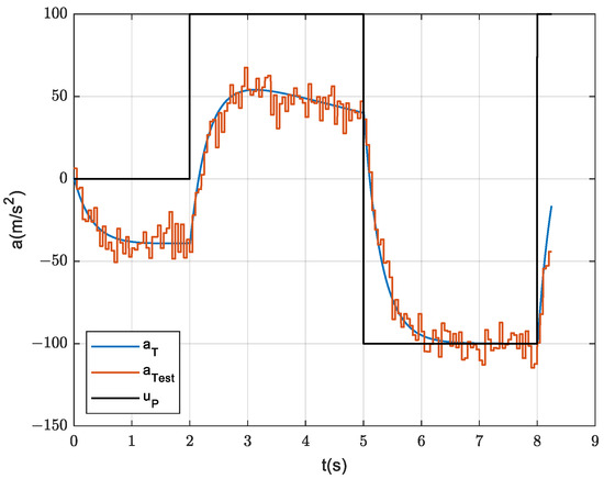
Figure 7.
Normal acceleration of the target with a random noise.
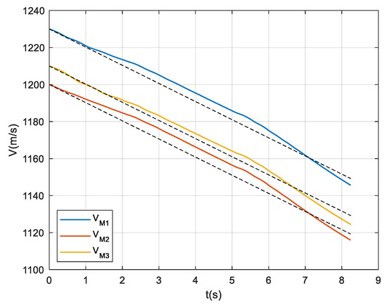
Figure 8.
Flight speeds of the three interceptors in the complex flight environment.

Figure 9.
Normal accelerations of the three interceptors in the complex flight environment.
A ballistic simulation is performed based on the simulation parameters listed in Table 1 and the target’s maneuver form shown in Equation (47). The three interceptors successfully intercept the target at 8.241 s, 8.238 s, and 8.247 s with miss distances of 1.2621 m, 4.0513 m, and 3.4692 m, respectively. The ballistics trajectories are shown in Figure 10.
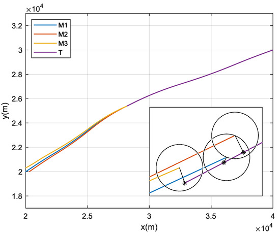
Figure 10.
Ballistics trajectories in the complex flight environment.
Figure 8 and Figure 9 show that Assumptions 5 and 6 are largely valid under the conditions of considering the aerodynamic characteristics of missiles. From the ballistic trajectories shown in Figure 10, the small ballistic inclinations required by Assumption 4 are difficult to ensure during the offense-defense confrontations. However, in general, the proposed guidance law is robust enough to overcome a certain degree of guidance information errors and model linearization biases and basically achieve the expected collision-free simultaneous interception.
5.3. Various Target’s Maneuver Forms
Since the target’s maneuver forms during the interception process is unknown to the missile swarm, based on Section 5.2, three special target’s maneuver forms shown in Figure 11 are set up for ballistic simulations to further verify the interception performance of the proposed guidance law.

Figure 11.
Three special target’s maneuver forms.
The simulation results are shown in Table 2 and Figure 12, under the three scenarios, the missile swarm all realizes the effective near-simultaneous interceptions, which suggests that, within the maximum range of the target’s preprogrammed command, the proposed guidance law could ensure the interception capability of the missile swarm. If the target does not set up an escape maneuver, the missile swarm can identify its intention.

Table 2.
Simulation results under the three special target’s maneuver forms.

Figure 12.
Ballistics trajectories under the three special target’s maneuver forms.
After the above analysis and discussion, a method for evaluate the interception success rate of guidance law is proposed as follows combining with the engineering experience: Establish simulation models that can simulate more real flight environments, such as those with deviations in aerodynamic coefficients, atmospheric parameters and target position and velocity measurements, etc., and then perform Monte Carlo stochastic simulations considering various possible maneuver forms of the actual target. Based on the minimum miss distances of the multiple interceptors to determine whether a single simulation is successful or not, and then the interception success rate could be calculated.
6. Conclusions
To solve offense-defense confrontation problems of multi-missile cooperative intercepting a high-speed and large-maneuvering target, a differential game-based cooperative interception guidance law with collision avoidance is proposed. Based on the ballistic simulations in Section 5, the main conclusions of the study are summarized as follows.
- Compared to the classical homing guidance law PNG, when the interceptors do not have speed and significant overload advantages over the target, the proposed guidance law has superior guidance performance and is capable of achieving simultaneous interceptions without inter-missile collisions.
- Some of the assumptions for guidance law design proposed in Section 2 are not ideal in real flight environments, slightly affecting the interception time consensus, while the interception accuracy could still be guaranteed.
- The setting method for the parameters of the target performance index proposed in Section 4 enables the missile swarm to correctly identify the incoming target’s maneuvering intention and then to cope with various target’s maneuver forms.
7. Limitation of Study
As with the majority of studies, the study in this paper is subject to some limitations. On one hand, in the process of establishing relative motion models used for the guidance law design, the linearization steps carried out in (5), (7) and (9) request small values of the ballistic inclinations, On the other hand, the theoretical derivation of the proposed guidance law does not consider model uncertainties and disturbances, as well as the control saturation phenomena.
Due to the above limitations, the interception time consensus will be slightly affected in real flight environments, while the interception accuracy could still be guaranteed, which is reflected in the simulations of Section 5. To reduce the impact of deviations between ideal and real systems on the guidance performance, the fuzzy systems or fuzzy time series [43] would be considered in subsequent works to improve the guidance law design.
Author Contributions
Conceptualization, methodology, software and validation, X.Z. and X.W.; writing—original draft preparation, X.W. and Y.L.; writing—review and editing, Y.L.; Supervision, J.Y. All authors have read and agreed to the published version of the manuscript.
Funding
This research received no external funding.
Data Availability Statement
The data presented in this study are available on request from the corresponding author.
Conflicts of Interest
The authors declare no conflicts of interest.
Appendix A. Proof of Lemma 2
The scalar target-ground relative motion model is
Since the coefficient matrix of the state equation is non-constant, it is needed to derive from the physical meaning of state transition matrix, and then, the explicit expression of can be obtained.
Based on Assumption 5, the speed function of the target is set as
where is the target’s axial drag acceleration.
From the homogeneous state equation , the state variables are obtained as
where
From Equation (A3), the target’s zero-effort attack miss distance and its differential expression are obtained as
From the original state equation , Equation (A6) is rewritten as
where is the normal acceleration generated by target attitude changes and the response process of which is approximated in the inertial form. Considering the short response time, the steady-state value of is used for the subsequent derivation.
Substituting into Equation (A7) yields
where .
From Equations (A5) and (A8), it can be obtained that
The scalar target-ground relative motion model is established by Equation (A9).
Similarly, the state transition vectors and control coefficient functions in the scalar missile-target and inter-missile relative motion models are
The proof is completed. □
Appendix B. Proof of the Target’s Optimal Penetration Strategy
Based on Equations (15), (16) and (21), the target Hamiltonian function is established as
where and are the costate variables introduced corresponding to the target-ground and missile-target relative motion respectively.
The costate equation and boundary condition of the target-ground relative motion are
the boundary conditions discussed in this paper are established on the basis of fixed terminal moment, is a time-varying parameter rather than a variable to be solved.
From Equation (A13), it can be obtained that
The costate equation and boundary condition of the missile-target relative motion are
From Equation (A15), it can be obtained that
The extremum condition of the target optimal control is
Based on Equations (A14), (A16) and (A17), the target optimal control is derived as
In Equation (A18), the zero-effort attack miss distance at the terminal moment notated as cannot be directly used to calculation, and it is converted to the current moment according to the differential expression of the zero-effort attack miss distance.
Integrating Equation (15) and substituting Equation (A18) yields
where
Equation (A19) is rewritten as
Substituting Equation (A21) into Equation (A18), the target optimal penetration strategy is derived as
The proof is completed. □
Appendix C. Proof of the Interceptor Optimal Interception Strategy
Based on Equations (16), (17) and (30), the interceptor Hamiltonian function is established as
where and are the costate variables introduced corresponding to the missile-target and inter-missile relative motion respectively.
The costate equation and boundary condition of the missile-target relative motion are
From Equation (A24), it can be obtained that
The costate equation, boundary condition and interior point constraint condition of the inter-missile relative motion are
From Equation (A26), it can be obtained that
According to Equation (8), is consistently true, i.e., is always equal to 1.
The extremum condition of the interceptor optimal control is
where and denote collisions associated with the kth interceptor.
Based on Equations (A25), (A27) and (A28), the interceptor optimal control is derived as
where
In Equation (A29), the Lagrange multipliers need to be solved according to the interceptors’ constraints. For ease of understanding, the following derivation introduces α and β to denote the index of an arbitrary interceptor and an arbitrary collision, respectively.
Integrating Equation (16) and substituting Equations (A18) and (A29) yields
According to Equations (31) and (A31), the interception constraint of the kth interceptor is expressed as
where
According to Equation (A32), the matrix expression of the interceptors’ interception constraint is
where
with denoting the vector of interception miss distances required by interception constraint.
Integrating Equation (17) and substituting Equation (A29) yields
where and denote the collisions associated with the interceptor.
According to Equations (31) and (A37), the collision avoidance constraint of the ith and the jth interceptors is expressed as
where s denotes the index of the collision between the ith and the jth interceptors, and
According to Equation (A38), the matrix expression of the interceptors’ collision avoidance constraint is
where
with denoting the vector of approach distances required by collision avoidance constraint.
From Equations (A35) and (A41), it can be obtained that
where
Substituting Equation (A44) into Equation (A29), the interceptor optimal interception strategy is derived as
The proof is completed. □
Appendix D. Proof of Proposition 3
Based on Equations (A29) and (A44), the performance index of the interceptors is expressed as
where the first five terms on the right of the equal sign are independent of , therefore, the optimal value of should satisfy
where , , is the sth component of .
The solution method of Equation (A48) is presented in [41], and due to the complexity of its computational steps, is optimized as follows in this paper.
where is the sth component of .
The proof is completed. □
References
- Yao, Y.; Yu, W.; Yang, L.; Chen, W. A Survey of Multi-Missile Cooperative Guidance Technology. Aerodyn. Missile J. 2021, 112–121. [Google Scholar]
- Zhou, M.; Wang, Y.; Guo, J.; Lu, X. A Survey of Multi-Missile Cooperative Terminal Guidance. Aero Weapon. 2023, 30, 17–25. [Google Scholar]
- Yang, J. Guidance and Control of Modern Missiles; Northwestern Polytechnical University Press: Xi’an, China, 2016. [Google Scholar]
- Wang, L. Study on Optimization and Design Approach for Multiple Flight Vehicles Cooperative Interception Based on Area Coverage. Ph.D. Thesis, Harbin Institute of Technology, Harbin, China, 2018. [Google Scholar]
- Liu, S.; Yan, B.; Zhang, T.; Zhang, X.; Yan, J. Coverage-Based Cooperative Guidance Law for Intercepting Hypersonic Vehicles with Overload Constraint. Aerosp. Sci. Technol. 2022, 126, 107651. [Google Scholar] [CrossRef]
- Su, W.; Li, K.; Chen, L. Coverage-Based Three-Dimensional Cooperative Guidance Strategy against Highly Maneuvering Target. Aerosp. Sci. Technol. 2019, 85, 556–566. [Google Scholar] [CrossRef]
- Liu, S.; Yan, B.; Zhang, T.; Zhang, X.; Yan, J. Three-Dimensional Coverage-Based Cooperative Guidance Law with Overload Constraints to Intercept a Hypersonic Vehicle. Aerosp. Sci. Technol. 2022, 130, 107908. [Google Scholar] [CrossRef]
- Liu, S.; Yan, B.; Liu, R.; Dai, P.; Yan, J.; Xin, G. Cooperative Guidance Law for Intercepting a Hypersonic Target with Impact Angle Constraint. Aeronaut. J. 2022, 126, 1026–1044. [Google Scholar] [CrossRef]
- Tan, S.; Lei, H.; Wang, B. Cooperative Guidance Law for Hypersonic Targets with Constrained Impact Angle. Trans. BeiJing Inst. Technol. 2019, 39, 597–602. [Google Scholar]
- You, H.; Chang, X.; Zhao, J.; Wang, S.; Zhang, Y. Three-Dimensional Impact-Angle-Constrained Fixed-Time Cooperative Guidance Algorithm with Adjustable Impact Time. Aerosp. Sci. Technol. 2023, 141, 108574. [Google Scholar] [CrossRef]
- Wei, M.; Cui, Z.; Li, Y. Review and Future Development of Multi-Missile Coordinated Interception. Acta Aeronaut. Astronaut. Sin. 2020, 41, 29–36. [Google Scholar]
- Isaacs, R. Differential Games; John Wiley & Sons: New York, NY, USA, 1965. [Google Scholar]
- Isaacs, R. Research Memoranda RM-1391, RM-1399, RM-1411, RM-1468; RAND Corporation: Santa Monica, CA, USA, 1956. [Google Scholar]
- von Neumann, J.; Morgenstern, O. Theory of Games and Economic Behaviour; Princeton University Press: Princeton, NJ, USA, 1944. [Google Scholar]
- Nash, J.F. Equilibrium Points in n -Person Games. Proc. Natl. Acad. Sci. USA 1950, 36, 48–49. [Google Scholar] [CrossRef]
- Bryson, A.E.; Ho, Y.-C. Applied Optimal Control: Optimization, Estimation, and Control; John Wiley & Sons: New York, NY, USA, 1975. [Google Scholar]
- Saridis, G.N. On a Class of Performance-Adaptive Self-Organizing Control Systems. In Pattern Recognition and Machine Learning; Fu, K.S., Ed.; Springer: Boston, MA, USA, 1971; pp. 204–220. [Google Scholar]
- Jond, H.B.; Platoš, J. Differential Game-Based Optimal Control of Autonomous Vehicle Convoy. IEEE Trans. Intell. Transport. Syst. 2023, 24, 2903–2919. [Google Scholar] [CrossRef]
- Zhao, S.; Qin, L.; Zhou, X.; Zhang, D. Optimized Power Control Algorithm Based on Differential Game Theory in Cognitive Radio Networks. In Proceedings of the 2022 41st IEEE Chinese Control Conference (CCC), Hefei, China, 25 July 2022; pp. 6951–6956. [Google Scholar]
- An, E.; Sun, Q.; Hu, J.; Wang, R. A Differential Game Approach to Distributed Energy Trading for Energy Internet. In Proceedings of the 2020 IEEE 4th Conference on Energy Internet and Energy System Integration (EI2), Wuhan, China, 30 October 2020; pp. 3608–3613. [Google Scholar]
- Guo, Z.; Zhou, S. Research on Cooperative Differential Game Guidance Law for Multi-Missile. J. Ordnance Equip. Eng. 2019, 40, 21–25. [Google Scholar]
- Guo, Z.; Zhou, S.; Yu, Y. Research of Cooperative Norm Differential Games Guidance Law for Intercepting a Maneuvering Target. Comput. Simul. 2020, 37, 23–26. [Google Scholar]
- Hua, W.; Zhang, Y.; Zhang, J.; Meng, Q. Differential Game Guidance Law for Double Missiles with Cooperative Intercept Angle. J. Chin. Inert. Technol. 2016, 24, 838–844. [Google Scholar]
- Shaferman, V.; Shima, T.Y. A Cooperative Differential Game for Imposing a Relative Intercept Angle. In Proceedings of the AIAA Guidance, Navigation, and Control Conference, Grapevine, TX, USA, 9 January 2017. [Google Scholar]
- Su, S.; Xie, Y.; Bai, Y.; Liu, Y.; Shan, Y. Research on Differential Game Cooperative Confrontation Guidance Law Method. Air Space Def. 2022, 5, 58–64. [Google Scholar]
- Shima, T.; Shinar, J. Time-Varying Linear Pursuit-Evasion Game Models with Bounded Controls. J. Guid. Control Dyn. 2002, 25, 425–432. [Google Scholar] [CrossRef]
- Hua, W.; Chen, X. Nonlinear Bounded-Control Differential Game Guidance Law for Variable-Speed Missiles. Control Decis. 2011, 26, 1886–1890. [Google Scholar]
- Mishley, A.; Shaferman, V. Linear Quadratic Guidance Laws with Intercept Angle Constraints and Varying Speed Adversaries. J. Guid. Control Dyn. 2022, 45, 2091–2106. [Google Scholar] [CrossRef]
- Gutman, S. Superiority of Canards in Homing Missiles. IEEE Trans. Aerosp. Electron. Syst. 2003, 39, 740–746. [Google Scholar] [CrossRef]
- Zhu, D.; Zheng, Y.; Ren, Q.; Sun, P. Differential Game Guidance Law for 3-Party Game with Incomplete Information. In Proceedings of the 2021 IEEE China Automation Congress (CAC), Beijing, China, 22 October 2021; pp. 2003–2008. [Google Scholar]
- Zhang, J.; Wang, F. Optimal Control: Mathematical Theory and Intelligent Methods; Tsinghua University Press: Beijing, China, 2017. [Google Scholar]
- Hao, G.; Lv, Q.; Huang, Z.; Zhao, H.; Chen, W. UAV Path Planning Based on Improved Artificial Potential Field Method. Aerospace 2023, 10, 562. [Google Scholar] [CrossRef]
- Liu, C.; Xie, F.; Ji, T. Fixed-Wing UAV Formation Path Planning Based on Formation Control: Theory and Application. Aerospace 2023, 11, 1. [Google Scholar] [CrossRef]
- Fiorini, P.; Shiller, Z. Motion Planning in Dynamic Environments Using Velocity Obstacles. Int. J. Robot. Res. 1998, 17, 760–772. [Google Scholar] [CrossRef]
- Chakravarthy, A.; Ghose, D. Obstacle Avoidance in a Dynamic Environment: A Collision Cone Approach. IEEE Trans. Syst. Man Cybern.—Part A Syst. Hum. 1998, 28, 562–574. [Google Scholar] [CrossRef]
- Han, S.-C.; Bang, H.; Yoo, C.-S. Proportional Navigation-Based Collision Avoidance for UAVs. Int. J. Control Autom. Syst. 2009, 7, 553–565. [Google Scholar] [CrossRef]
- Tony, L.A.; Ghose, D.; Chakravarthy, A. Precision UAV Collision Avoidance Using Computationally Efficient Avoidance Maps. In Proceedings of the 2018 AIAA Guidance, Navigation, and Control Conference, Kissimmee, FL, USA, 8 January 2018. [Google Scholar]
- Chen, S.; Ma, D.; Yao, Y.; Wang, X.; Li, C. Cooperative Polynomial Guidance Law with Collision Avoidance and Flight Path Angle Coordination. Aerosp. Sci. Technol. 2022, 130, 107809. [Google Scholar] [CrossRef]
- Mylvaganam, T.; Sassano, M.; Astolfi, A. A Differential Game Approach to Multi-Agent Collision Avoidance. IEEE Trans. Autom. Control 2017, 62, 4229–4235. [Google Scholar] [CrossRef]
- Weiss, M.; Shima, T. Linear Quadratic Optimal Control-Based Missile Guidance Law with Obstacle Avoidance. IEEE Trans. Aerosp. Electron. Syst. 2019, 55, 205–214. [Google Scholar] [CrossRef]
- Kumar, S.R.; Weiss, M.; Shima, T. Minimum-Effort Intercept Angle Guidance with Multiple-Obstacle Avoidance. J. Guid. Control Dyn. 2018, 41, 1355–1369. [Google Scholar] [CrossRef]
- Jha, B.; Tsalik, R.; Weiss, M.; Shima, T. Cooperative Guidance and Collision Avoidance for Multiple Pursuers. J. Guid. Control Dyn. 2019, 42, 1506–1518. [Google Scholar] [CrossRef]
- Bajestani, N.S.; Kamyad, A.V.; Zare, A. A Piecewise Type-2 Fuzzy Regression Model. IJCIS 2017, 10, 734. [Google Scholar] [CrossRef]
Disclaimer/Publisher’s Note: The statements, opinions and data contained in all publications are solely those of the individual author(s) and contributor(s) and not of MDPI and/or the editor(s). MDPI and/or the editor(s) disclaim responsibility for any injury to people or property resulting from any ideas, methods, instructions or products referred to in the content. |
© 2024 by the authors. Licensee MDPI, Basel, Switzerland. This article is an open access article distributed under the terms and conditions of the Creative Commons Attribution (CC BY) license (https://creativecommons.org/licenses/by/4.0/).