Abstract
During the process of capturing non-cooperative targets in space, space robots have strict constraints on the position and orientation of the end-effector. Traditional methods typically focus only on the position control of the end-effector, making it difficult to simultaneously satisfy the precise requirements for both the capture position and posture, which can lead to failed or unstable grasping actions. To address this issue, this paper proposes a reinforcement learning-based capture strategy learning method combined with posture planning. First, the structural models and dynamic models of the capture mechanism are constructed. Then, an end-to-end decision control model based on the Optimistic Actor–Critic (OAC) algorithm and integrated with a capture posture planning module is designed. This allows the strategy learning process to reasonably plan the posture of the end-effector to adapt to the complex constraints of the target capture task. Finally, a simulation test environment is established on the Mujoco platform, and training and validation are conducted. The simulation results demonstrate that the model can effectively approach and capture multiple targets with different postures, verifying the effectiveness of the proposed method.
1. Introduction
Over the past few decades, numerous countries have vigorously launched various types of spacecraft for military, commercial, and other goals due to the rapid advancement of space science and technology [1]. Spacecraft become defunct spacecraft and space debris when their service lives are coming to an end. The number of defunct spacecraft and space debris in orbit is currently immense, nearing a critical threshold [2]. This results in increasingly scarce orbital resources and a heightened probability of collisions. Consequently, using on-orbit servicing technologies to deorbit and remove defunct spacecraft has become a focal point in the aerospace sector globally [3]. Space robots, as effective actuators in space operations, hold significant value in satellite fault repair, space debris removal, and the assembly of large space facilities, both in theoretical research and engineering applications [4]. Therefore, a great deal of study has been performed on space robot dynamics and control [5]. Space robotic arms operate very differently from terrestrial robotic arms because of the microgravity environment there [6]. This makes motion planning for space robotic systems a challenging task.
A space robotic system typically comprises three main components: a base platform, a robotic arm attached to the base, and an end-effector for capture. When performing on-orbit tasks, space robots face significant challenges due to the uncertainties in the motion of the target spacecraft, which may lead to unpredictable disturbances upon contact [7]. Moreover, the robotic arm and the end-effector form a highly coupled dynamic system, where the movements of the arm affect the stability of the end-effector [8]. These issues present substantial challenges for the stable control of space robots in orbit, directly impacting the success of on-orbit servicing missions. To address these challenges, numerous researchers have proposed efficient solutions for capturing tasks performed by space robots. Yu et al. [9] investigated the dynamics modeling and capture tasks of a space-floating robotic arm with flexible solar panels when dealing with non-cooperative targets. Cai et al. [10] addressed the contact point configuration problem in capturing non-cooperative targets using an unevenly oriented distribution joint criterion method. This approach combines virtual symmetry and geometric criteria, ensuring stable grasping through geometric calculations and optimizing the selection and distribution of contact points to enhance capture stability and efficiency. Zhang et al. [11] proposed a pseudospectral-based trajectory optimization and reinforcement learning-based tracking control method to mitigate reaction torques induced by the robotic arm, focusing on mission constraints and base–manipulator coupling issues. Aghili et al. [12] developed an optimal control strategy for the close-range capture of tumbling satellites, switching between different objective functions to achieve either the time-optimal control of target capture or the optimal control of the joint velocities and accelerations of the robotic arm. Richard et al. [13] employed predictive control to forecast the motion of tumbling targets, controlling the end-effector to track and capture the target load, and limiting the acceleration of the arm joints to avoid torque oscillations due to tracking errors at the moment of capture. Jayakody et al. [14] redefined the dynamic equations of free-flying space robots and applied a novel adaptive variable structure control method to achieve robust coordinated control, unaffected by system uncertainties. Xu et al. [15] proposed an adaptive backstepping controller to address uncertainties in the kinematics, dynamics, and end-effector of space robotic arms, ensuring asymptotic convergence of tracking errors compared to traditional dynamic surface control methods. Hu et al. [16] designed a decentralized robust controller using a decentralized recursive control strategy to address trajectory-tracking issues in space manipulators. The aforementioned capture strategies for space robotic arms are all based on multi-body dynamic models. However, accurately establishing such models is challenging, and strict adherence to these models can result in significant position and velocity deviations, excessive collision forces, or capture failures.
In recent years, the rapid development of artificial intelligence technology has provided new avenues for solving space capture problems, integrating the advantages of optimal control with traditional methods [17]. The research and application of deep reinforcement learning (DRL) algorithms have progressed swiftly, finding uses in autonomous driving [18], decision optimization [19], and robotic control [20]. These algorithms adjust network parameters through continuous interaction between the agent and the environment, deriving optimal strategies and thus avoiding the complex modeling and control parameter adjustment processes. Using reinforcement learning to advance capture technology has become a prominent research focus. Deep reinforcement learning algorithms such as Proximal Policy Optimization (PPO) [21], Deep Deterministic Policy Gradient (DDPG) [22], and Soft Actor–Critic (SAC) [23] have been applied to solve planning problems for space robots. Yan et al. [24] employed the Soft Q-learning algorithm to train energy-based path planning and control strategies for space robots, providing a reference for capture missions. Li et al. [25] propose a novel motion planning approach for a 7-degree-of-freedom (DOF) free-floating space manipulator, utilizing deep reinforcement learning and artificial potential fields to ensure robust performance and self-collision avoidance in dynamic on-orbit environments. Lei et al. [26] introduced an active target tracking scheme for free-floating space manipulators (FFSM) based on deep reinforcement learning algorithms, bypassing the complex modeling process of FFSM and eliminating the need for motion planning, making it simpler than traditional algorithms. Wu et al. [27] addressed the problem of optimal impedance control with unknown contact dynamics and partially measured parameters in space manipulator tasks, proposing a model-free value iteration integral reinforcement learning algorithm to approximate optimal impedance parameters. Cao et al. [28] incorporated the EfficientLPT algorithm, integrating prior knowledge into a hybrid strategy and designing a more reasonable reward function to improve planning accuracy. Wang et al. [29] developed a reinforcement learning system for motion planning of free-floating dual-arm space manipulators when dealing with non-cooperative objects, achieving successful tracking of unknown state objects through two modules for multi-objective trajectory planning and target point prediction. These advancements in reinforcement learning algorithms represent significant strides in enhancing the performance and reliability of space capture missions, offering promising alternatives to traditional control methods.
The aforementioned research primarily focuses on the position planning of the end-effector, ignoring the importance of the end-effector’s orientation and the non-cooperative nature of the target. Considering only the motion planning of the end-effector’s position may result in a mismatch between the end-effector and the target’s orientation. Particularly when a specific orientation is required for capture, neglecting the importance of the end-effector’s orientation can result in ineffective or unstable captures, thereby affecting the overall mission success. In space capture missions, the uncertainty in parameters such as the shape, size, and motion state of non-cooperative targets significantly increases the control precision requirements for space robotic arms. Reinforcement learning algorithms face challenges in training optimal capture strategies due to these uncertainties. To overcome these limitations, this paper proposes a motion planning method that comprehensively considers both the position and orientation of the end-effector, aiming to achieve efficient, stable, and safe capture by the robotic arm’s end-effector. Specifically, the proposed approach decomposes the capture task of non-cooperative targets into two stages: the approach phase of the robotic arm and the capture phase of the end-effector. First, an orientation planning network is established to plan the capture pose of the end-effector based on the target’s orientation. Then, deep reinforcement learning methods are introduced to transform the control problems of position, torque, and velocity of the robotic arm during the capture process into a high-dimensional target approximation problem. By setting a target reward function, the end-effector’s position and motion parameters are driven to meet the capture conditions, achieving stable and reliable capture and deriving the optimal capture strategy. The main contributions of this paper are as follows:
- (1)
- Constructing the structural model of the space robotic arm, defining its physical parameters, and establishing the dynamic model;
- (2)
- Designing a deep reinforcement learning algorithm that integrates capture orientation planning to develop a space robotic arm controller, obtaining the optimal capture strategy to achieve stable and reliable capture;
- (3)
- Establishing a simulation environment to validate the superiority of the proposed algorithm in controlling the capture of non-cooperative targets.
The rest of this paper is organized as follows: Section 2 provides a detailed description of the problem of capturing non-cooperative targets with space robots. Section 3 presents the proposed grasping posture planning method for common targets, establishes a reinforcement learning algorithm control framework, and designs the reward function. Section 4 describes the simulation test environment and presents the simulation results and discussion. Additionally, the conclusions of this work are given in Section 5.
2. Problem Description and System Modeling
2.1. Problem Description
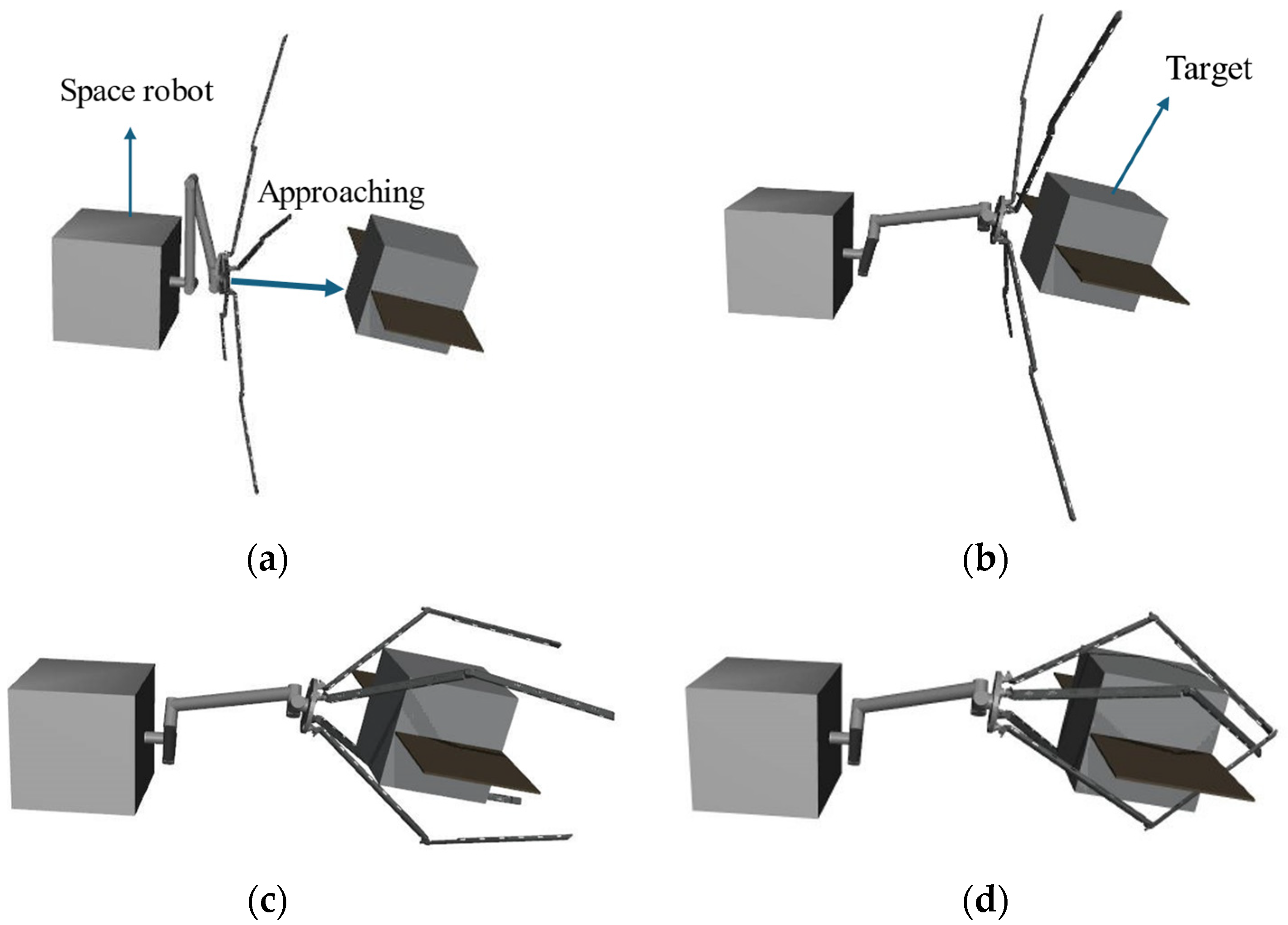
The completion of on-orbit capture tasks by space robots generally involves three phases [30]: observation and identification, autonomous approach to the target spacecraft, and target capture and post-capture stabilization. This paper focuses on the phases of approaching the target spacecraft and the capture and post-capture stages. A schematic diagram illustrating the capture of a non-cooperative target in a space environment is shown in Figure 1. The specific capture process is as follows: the space robot maneuvers to within a capturable range of the target and maintains a stable hover relative to the non-cooperative target. The robotic arm then moves the end-effector to the capture point based on the target’s position and orientation. Subsequently, the end-effector closes, connecting the space robot and the target into a single, stable composite entity.
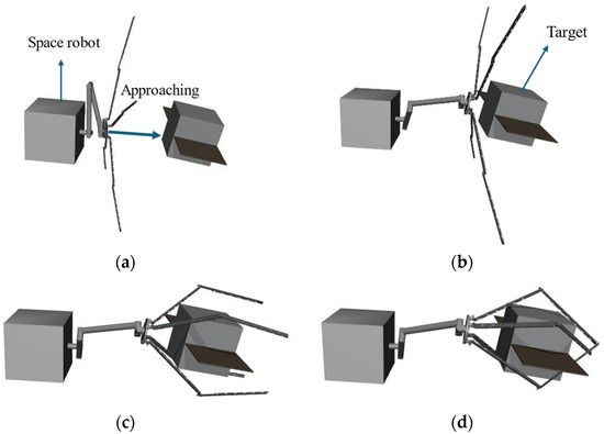
Figure 1.
Schematic of space robot capturing a non-cooperative target. (a) Initial state; (b) approaching phase; (c) enveloping phase; and (d) grasped.
The ideal outcome of a space robot capturing a non-cooperative target is shown in Figure 2a, when the capture mechanism approaches the target at the correct angle, the grasping process is smooth, and the target is secured firmly. If the grasping angle is inappropriate, as illustrated in Figure 2b, the capture mechanism may fail to make proper contact or stably grasp the target, resulting in unintended movement of the target and capture failure.

Figure 2.
Comparison of capture states. (a) Desired grasp and (b) capture failure.
During the approach and on-orbit capture process of a space robot, a misalignment between the orientation of the end-effector and the target can lead to unstable captures or even capture failures, especially when the attitude of the target spacecraft is uncertain. Additionally, as the robotic arm approaches the target, the mass parameters of the space robot system may change. The movements of the robotic arm and the capture mechanism form a highly coupled dynamic system, significantly increasing the difficulty of joint control. Moreover, the end-effector must adopt different closure strategies based on the characteristics of various targets to ensure a successful and stable capture. Therefore, it is essential to precisely plan the joint angles and angular velocity time curves while ensuring that the actual constraints of the capture domain are met. The following reasonable assumptions are made for the study:
- (1)
- Both the capture platform and the target are rigid body systems.
- (2)
- The base posture of the space robot is controllable, allowing the robotic arm to be treated as a fixed-base scenario.
- (3)
- The drive joints use torque motors, neglecting nonlinear factors such as backlash and flexibility.
- (4)
- Simulation experiments are conducted on a simulation platform, ignoring the interference effects of individual parts of the model.
2.2. Dynamic Model of the Space Robotic Arm System
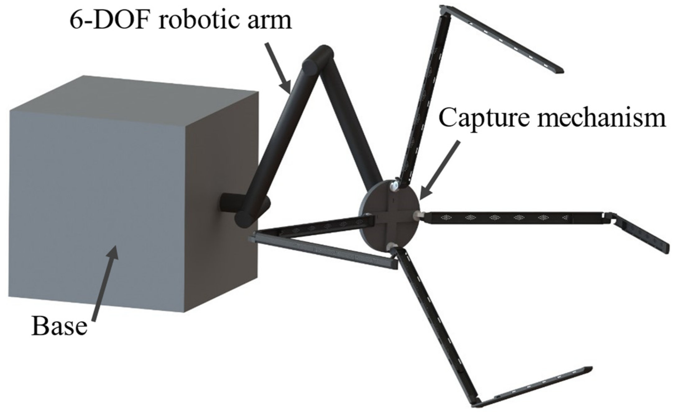
The structure of the space robot is divided into three parts: a base, a 6-DOF robotic arm, and an end-effector with four fingers and eight joints, as illustrated in Figure 3. The base serves as the fixed platform for the entire system, providing a robust and stable support structure to ensure the robot remains steady while performing tasks. The 6-DOF robotic arm is composed of six jointed links, each capable of rotating freely along different axes, enabling complex spatial positioning and attitude control. The end-effector, which is a critical component of the space robot, is responsible for executing precise capture tasks. It is composed of four fingers, each equipped with two independent rotational joints, resulting in a total of eight degrees of freedom. These joints allow the fingers to adjust their angles flexibly to accommodate objects of varying shapes and sizes. During capture operations, the four fingers rotate towards each other around their axes, forming an enclosure around the target. They continue rotating until the target is securely locked in place, forming a rigid connection with the gripper.
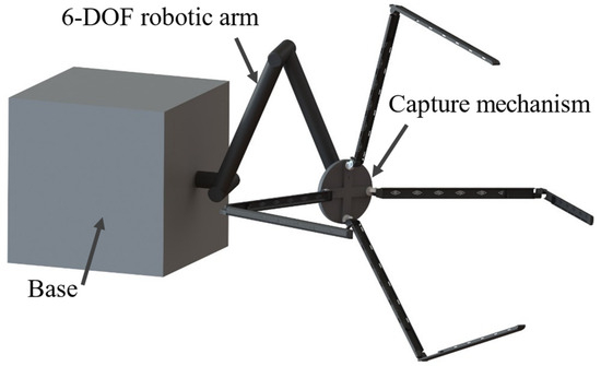
Figure 3.
Schematic diagram of the space robot structure.
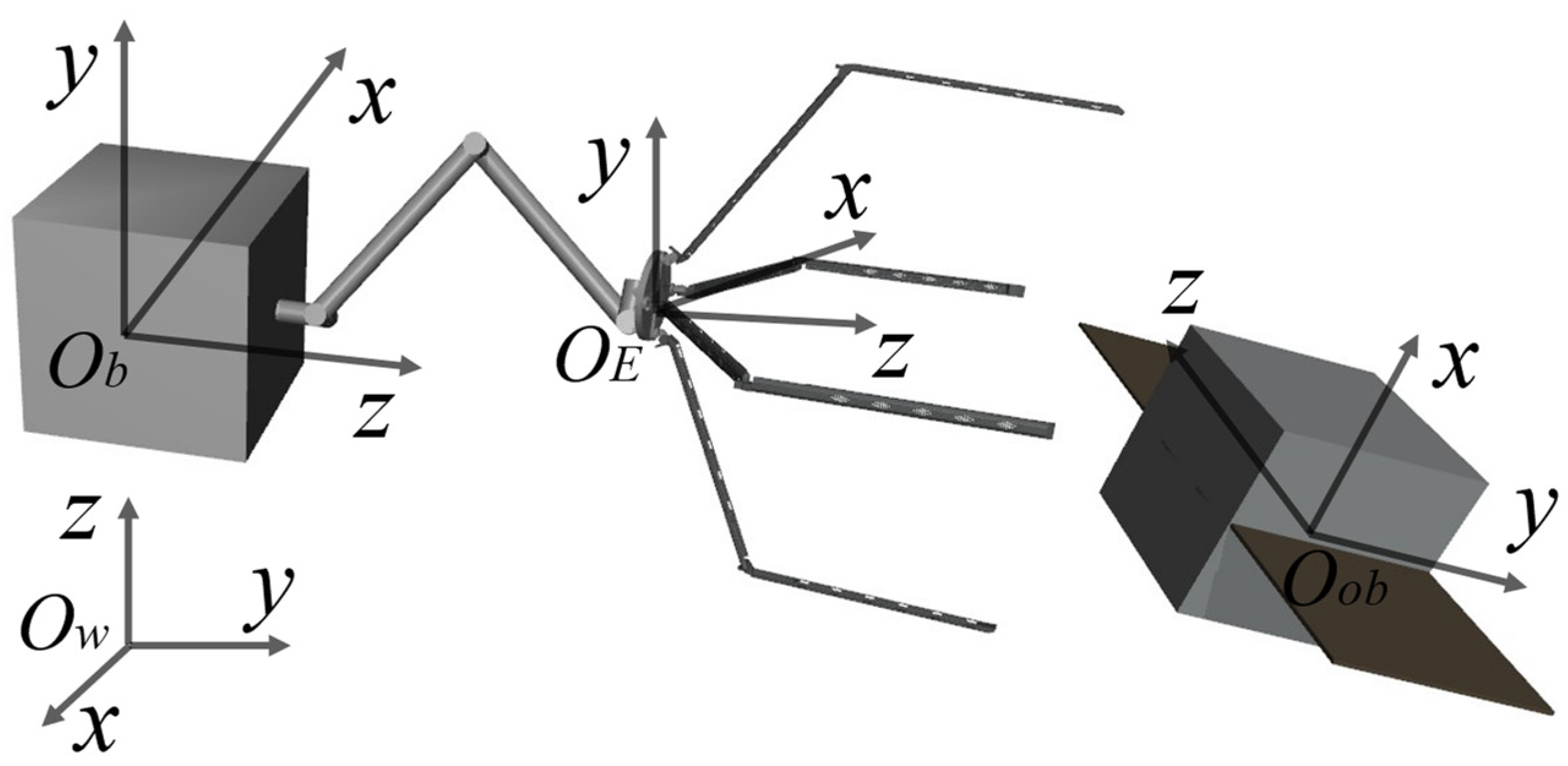
The corresponding coordinate systems are then established, as shown in Figure 4. The world coordinate system defines the basic framework for the entire simulation scene, serving as the standard for relative position transformations between other coordinate systems. The base coordinate system is used as the standard for relative position transformations of the robotic arm’s joint coordinate systems, link coordinate systems, and end-effector coordinate systems. The end-effector coordinate system has its origin defined on the symmetry axis of the end-effector. The z-axis of this coordinate system coincides with the symmetry axis and points in the direction of the finger opening/closing movement. The target coordinate system defines the framework for the target to be captured, describing the relative position and orientation between the target and the world coordinate system, and providing measurement metrics for the robotic arm’s capture process.
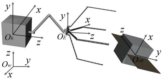
Figure 4.
Relative positions between coordinate systems.
In this paper, the dynamic model is derived based on the Lagrangian method. The total kinetic energy of the robotic arm system is the sum of the kinetic energies of each component. The kinetic energy of each link and joint can be composed of the translational kinetic energy of its center of mass and the rotational kinetic energy of its angular velocity; therefore, the total kinetic energy of the space robotic arm system can be expressed as follows:
Assuming microgravity is negligible, the total potential energy . Therefore, the Lagrangian function is . In the on-orbit capture system described in this paper, the pose of the service satellite is controllable, allowing the robotic arm to be treated as a fixed-base scenario. Consequently, the redundant robotic arm dynamic model constructed using the Lagrangian method is:
where denotes the joint torques of the robotic arm; denotes the inertia matrix of the robotic arm; denotes the Coriolis matrix of the robotic arm; denotes the gravity torque vector, which can be neglected in the space environment; and , , and represent the joint positions, joint velocities, and joint accelerations of the robotic arm, respectively.
3. Capture Control Strategy
Reinforcement learning (RL) learns through the interaction between an agent and the environment, continually attempting to obtain the optimal policy for the current task. This learning algorithm does not require an accurate dynamic model, making it widely applicable [31]. Reinforcement learning treats the decision-making process as a Markov process, which consists of a series of state and action interactions over discrete time steps. RL guides the agent to choose the optimal policy in the future through the value function of the current state and available actions. The agent learns and gradually improves its policy in the environment to maximize cumulative future rewards. This Markov decision process-based modeling method provides RL with significant flexibility and applicability in handling real-world problems characterized by uncertainty and complex dynamics. Therefore, applying RL to the design of space robot controllers endows them with the capability of autonomous learning, and proactive adjustment of control strategies to adapt to changes in their dynamic structure and external environment. Through self-reinforcement learning amid changes, the controller continuously optimizes control strategies, enhancing the intelligence of the robotic arm’s movements and achieving optimal control performance.
3.1. DRL Algorithm Integrating Capture Pose Planning
This paper combines the grasping posture planning method with deep reinforcement learning, integrating the planned grasping posture information into the environmental state information. During the interactive learning process in the environment, the agent can more accurately perceive the pose information of the capture target. When deciding on capture actions, the agent comprehensively considers both the capture planning results and the reward information from reinforcement learning, thereby selecting the optimal capture strategy. However, traditional Actor–Critic algorithms face issues such as inefficient exploration in complex state and action spaces, susceptibility to local optima, and lengthy training times [32]. To address these issues, the SAC algorithm [33] employs double Q networks to estimate the lower bounds of Q values, thereby avoiding the problem of Q value overestimation that can render the agent’s learning strategy ineffective. Although double Q networks can effectively mitigate overestimation issues, the estimated Q values are approximations, leading to significant discrepancies between the estimated and true values. This discrepancy can cause the policy to concentrate, increasing the risk of the algorithm getting trapped in local optima. When applying DRL algorithms to solve the capture tasks of space robotic arms, it is essential to integrate the advantages of capture pose planning and reinforcement learning algorithms. The algorithm design should balance exploration efficiency, learning stability, and training efficiency to ensure the algorithm effectively learns the optimal control strategy. To solve the aforementioned problems, this paper adopts the OAC algorithm [34] with an optimistic exploration strategy to avoid the local optimization problem caused by strategy concentration.
The objective of the reinforcement learning task in this paper is to guide the space robot to learn an optimal capture policy through continuous exploration. This strategy maximizes the cumulative reward obtained by the space robot during its interactions with the environment. The policies can be expressed as follows:
where represents the entropy of the policy taking action in state ; is the reward function; is the action at time ; is the state–action distribution formed by the policy; and is the temperature coefficient, used to control the degree of policy exploration.
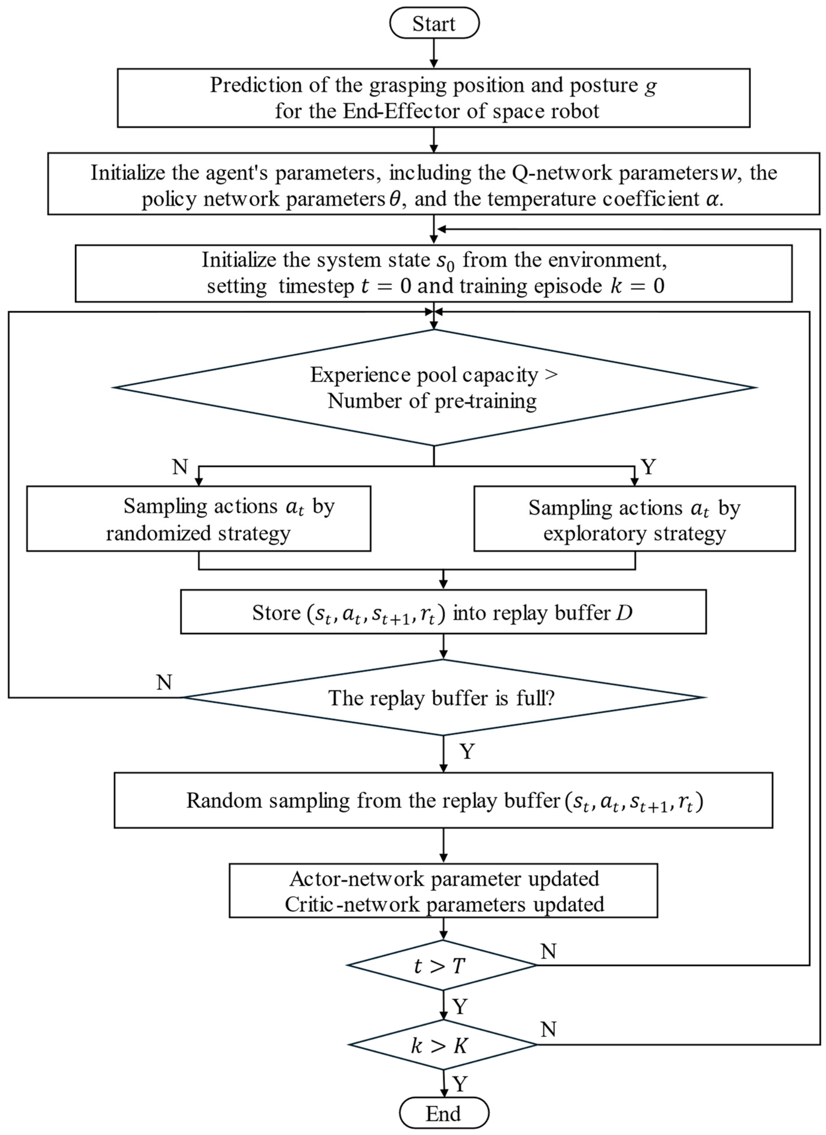
The implementation process of the DRL algorithm integrated with capture pose prediction is shown in Figure 5, and the specific update procedure is as follows:
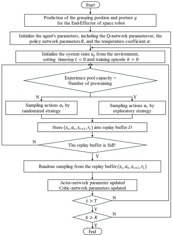
Figure 5.
Algorithm flowchart.
- (1)
- Plan the capture position and pose of the end-effector based on the target satellite’s position;
- (2)
- Initialize the parameters of each network;
- (3)
- Initialize the state from the state space;
- (4)
- If the experience pool capacity exceeds the pre-training number, calculate the exploration policy and sample action ; otherwise, sample actions using the random policy;
- (5)
- Pass the given actions into the environment to update the state and reward , and store the obtained data in the replay buffer ;
- (6)
- If the number of experience samples is less than the set size, go to step (4); otherwise, randomly sample data from the experience pool;
- (7)
- Input the sampled data into the agent to update the network parameters;
- (8)
- If the algorithm has been trained to the maximum number of episodes , terminate the training; otherwise, return to step (2).
3.2. Capture Pose Planning
The grasping posture of a space robotic arm has a crucial impact on the quality of capturing non-cooperative targets. In the space environment, due to the lack of external references and the reduced influence of gravity, the robotic arm needs to accurately determine the capture pose to ensure that the target object can be reliably captured and remain stable. A suitable capture pose not only increases the success rate of the capture but also reduces the instability of the pose generated during the capture process, thus ensuring the quality and efficiency of the capture. The capture pose is represented as , where P denotes the grasp center of the end-effector and R denotes the rotational pose of the end-effector. Based on the position and pose of the target object, the capture pose is obtained as follows:
where represents the planning network for the grasping posture, mapping the position and orientation of the target object to the position and rotational posture of the grasping device.
For the dataset required to train the prediction network, this paper uses the Mujoco210 physics simulation software to generate non-cooperative targets in a simulated environment. The position and pose of the non-cooperative targets within the capture range are varied, and each capture is annotated to create a capture dataset. This study targets square satellites with solar panels, planar debris, and rod-shaped space debris for capture. It considers actual gripping habits to avoid the capture mechanism pushing the target out of the capture area during the closure process, as shown in Figure 6. The blue areas in the figure represent the reasonable capture point regions. For square satellites with solar panels and planar debris, the capture region should be selected at the center of the satellite or debris, away from protruding structures like solar panels, to minimize the impact on the target’s pose. The gripper should perform the capture operation along the main axis of the target to ensure that the applied force is uniform during the capture process, effectively controlling the target’s pose and position. For rod-shaped targets, the capture region should be chosen in the middle of the cylinder, and the capture should be performed along the axial direction to ensure stability.

Figure 6.
Grasping regions for different targets. (a) Square satellite with solar panels; (b) planar debris; (c) rod-shaped debris.
3.3. Construction of the Agent Network
The network structure of the OAC algorithm primarily consists of the actor network and the critic network. The interaction process between these two networks is as follows: The agent first observes the current state information of the environment; subsequently, the actor network generates the current policy action based on this state information. After the agent executes this action, it transitions to the next state and receives a corresponding reward. This process constitutes a complete interaction with the environment. The critic network estimates the action-state value based on the current state information. Unlike traditional Actor–Critic methods, the OAC algorithm employs an optimistic initialization strategy, initializing the action value function with relatively high values to encourage the agent to explore the environment actively. Additionally, the OAC algorithm adopts a dynamic exploration mechanism, gradually decreasing the exploration rate based on the agent’s learning progress to balance exploration and exploitation during the learning process.
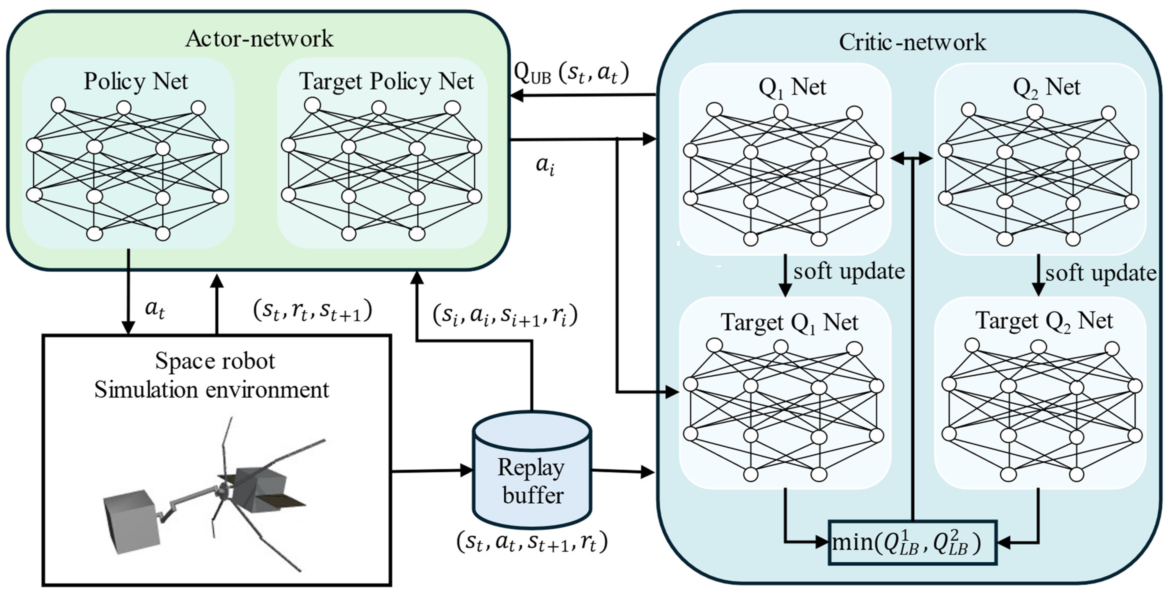
The entire network structure of the OAC algorithm, as shown in Figure 7, includes six networks. The actor network consists of the exploration policy network and the target policy network. The critic network includes four Q networks: Q1, Q2, and their corresponding target Q networks. Although Q1 and Q2 are identical in structure and training methods, their initial parameters differ. When calculating the target Q value, the smaller value between Q1 and Q2 is used to reduce bias in the Q value estimation. Additionally, by introducing uncertainty estimation, optimistic Q values are constructed to encourage the agent to explore. The actor network is a parameterized neural network that selects an appropriate action based on the current state, updating the parameters of the exploration policy network . The target actor network generates actions to calculate the target Q values when updating the critic network. Its network parameters are periodically updated from . The critic networks estimate the Q values of state–action pairs under the current policy, guiding the update of the actor network.
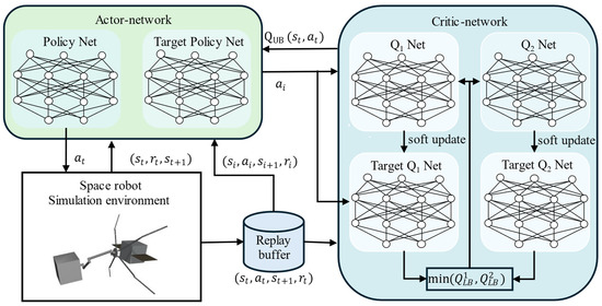
Figure 7.
Schematic diagram of the OAC algorithm control framework.
The Q function in the OAC algorithm establishes an approximate upper bound and a lower bound , each serving different purposes. The lower bound is used to update the policy, preventing overestimation by the critic network, thereby improving sample efficiency and stability. The upper bound is used to guide the exploration policy, selecting actions by maximizing the upper bound, which encourages the exploration of new and unknown regions in the action space, thus enhancing exploration efficiency. The lower bound is calculated using the Q values obtained from two Q function neural networks, and . These two networks have the same structure but different initial weight values.
where and represent the Q values obtained by the target Q function neural networks for the state–action pair ; is the reward discount factor; and denotes the probability distribution of selecting action in state . For the upper bound , it is defined using uncertainty estimation as follows:
where determines the importance of the standard deviation , effectively controlling the optimism level of the agent’s exploration. and are the mean and standard deviation of the estimated Q function, respectively, used to fit the true Q function.
3.4. Exploration Strategy Optimization in OAC Algorithm
To address the conservative exploration and low exploration efficiency issues in Actor–Critic algorithms, an optimistic exploration strategy is introduced. This strategy is only used by the agent to sample actions from the environment and store the obtained information in the experience pool. The primary purpose of introducing optimistic estimation is to encourage exploration by increasing the value estimation of actions with high uncertainty, thereby avoiding local optima. The exploration strategy is expressed as , where , can be calculated by the formula:
where is the temporal difference error, indicating the discrepancy between the exploration strategy and the target strategy; is the mean of the exploration strategy probability distribution; and is the covariance of the exploration strategy probability distribution. The mean and covariance obtained in this formula should satisfy the KL constraint to ensure the stability of OAC updates. Through the strategy , the agent is encouraged to actively explore unknown action spaces, avoiding local optima caused by policy convergence.
The parameters of the Q function neural network can be updated by minimizing the Bellman residual:
where represents the lower bound of the Q value obtained by the target Q function neural network; D represents the experience replay buffer; and represents the policy under the network parameters . The target policy network parameters are updated by minimizing the following equation:
The parameters of the target Q network are updated by:
where is the soft update coefficient.
The temperature coefficient, , is updated by minimizing :
where is updated through gradient descent to minimize this function and is the minimum desired entropy, typically set to the dimensionality of the action space.
According to the agent network framework and strategy optimization method described above, the algorithm pseudo-code is shown in Algorithm 1.
| Algorithm 1: DRL Algorithm Integrating Capture Pose Planning |
|
3.5. State Space and Action Space
The space manipulator system comprises a 6-DOF manipulator arm and an 8-DOF end-effector capture device. According to the reinforcement learning control strategy components, the state space of the system is defined as follows: , where represents the joint angles of the space manipulator and represents the corresponding joint angular velocities. , represents the position and orientation of the end-effector capture device, and represents the position and orientation of the captured target.
3.6. Reward Function Design
The design of the reward function plays a crucial role in reinforcement learning algorithms, as it aims to guide the agent in learning the optimal action strategy to accomplish the desired task. For the task of capturing non-cooperative targets in space, the reward function in this study considers the position and orientation of the manipulator’s movement as well as the capture mechanism’s grasping and enclosing of the target.
First, the position and orientation of the manipulator when moving to the capture point are considered. To ensure that the manipulator can effectively approach the target and maintain an appropriate orientation for capturing it, reward terms for the position and orientation errors are designed. The position error can be represented as the Euclidean distance between the end of the manipulator and the target, while the orientation error can be represented as the angular difference between the manipulator’s end and the target. Therefore, the reward terms for position and orientation errors are expressed as follows:
where is the Euclidean distance between the end-effector and the target, and is the angular difference between the end-effector and the target.
Second, the grasping and enclosing performance of the end-effector is considered. To incentivize the end-effector to perform effective grasping actions and avoid unnecessary damage, a reward term for the grasping effect is designed. The reward term for the grasping effect can be expressed as:
where the first term is the reward for the joint enclosing effect and represents the angle of the j-th joint on the i-th arm of the end-effector. The second term is the reward for the grasping stability of the capture mechanism. If the four fingers simultaneously contact the target within a certain time window, a reward is given. This setting effectively guides the agent to learn to achieve simultaneous contact with the target by all four fingers during the grasping process, thereby improving the success rate and stability of the capture task.
Finally, a time-step reward is set to keep the total training reward value within an appropriate range. The setting of this reward term does not affect the final result.
By weighting and summing all the reward terms according to their importance, the final reward function is:
where , , and are the coefficients corresponding to each reward term. The coefficients represent the importance of the corresponding reward terms. Based on multiple simulation experiments, the three parameters are set to , , and .
4. Simulation Analysis
In this section, we conduct physical simulation experiments to verify the effectiveness of the proposed space robot capture scheme. We use Mujoco as the reinforcement learning simulation training environment, which offers excellent modeling capabilities, speed, and accuracy, especially for robot control tasks, where Mujoco can accurately simulate the movement between joints. The space robot model is created and exported using SolidWorks, and the physical parameters of the space robot are saved. The training simulation environment for capturing non-cooperative targets by the space robot is constructed in the Mujoco physics simulation software. The simulation experiments are conducted in an Ubuntu 18.04 x64 operating system environment, with an Intel(R) Core(TM) i7-10700 CPU @ 2.90 GHz, 16.00 GB RAM, and an NVIDIA GeForce GTX 1660 Ti GPU. The program execution environment is Python 3.7.
4.1. Environment Configuration and Parameter Settings
To verify the characteristics of the capture strategy, the entire capture process is divided into two stages: The first stage involves arm movement, where the end-effector of the manipulator slowly approaches the target while the base maintains a fixed position. The end-effector adjusts to the planned angle and avoids collisions with the target during the approach. The second stage involves the end-effector closing in on and capturing the target within the capture domain. The design parameters for the space robot manipulator are shown in Table 1.

Table 1.
Simulation model parameter settings.
Based on the algorithm performance from multiple simulation experiments, the hyperparameters for reinforcement learning training are set as shown in Table 2.

Table 2.
Network hyperparameter settings.
4.2. Algorithm Verification Simulation
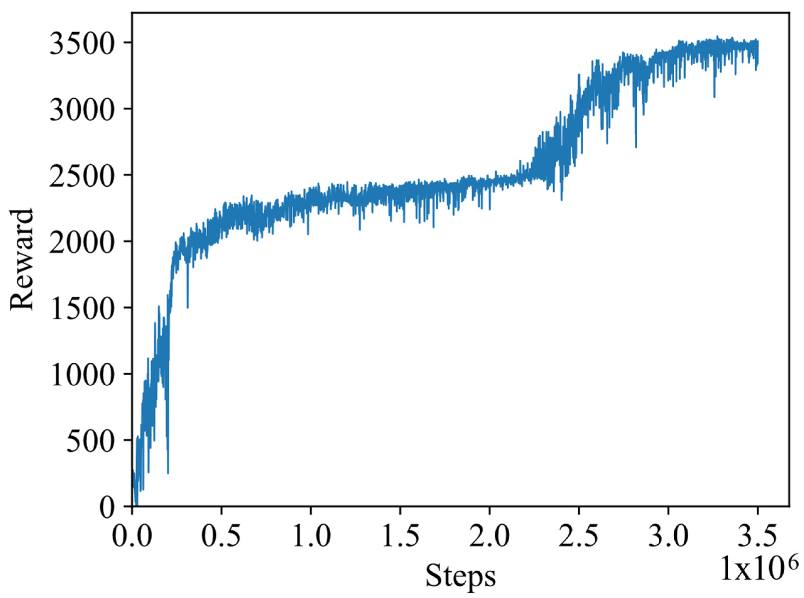
In this study, the simulation experiments adopt an end-to-end control method, where the joint motors control the angles and angular velocities of the manipulator by outputting control torques. Figure 8 shows the reward variations obtained during training in the algorithm configuration simulation model; the horizontal axis represents the training steps, while the vertical axis represents the rewards obtained during the training process. As shown in Figure 8, the reward value increases rapidly during the training steps from 0 to 500 k. From 500 k to 2200 k training steps, the reward increases slowly, and then it rises rapidly again from 2200 k to 3100 k steps. After 3100 k training steps, the reward value converges to around 34,000. The trend in reward variations indicates that the early-stage strategy learning focuses on the reward for the end-effector approaching the target. In the later stages, the strategy learning process continues to explore and focuses on the reward for capturing the target, ultimately learning a complete capture strategy that approaches and captures the target.
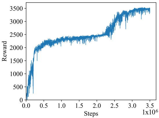
Figure 8.
Training process.
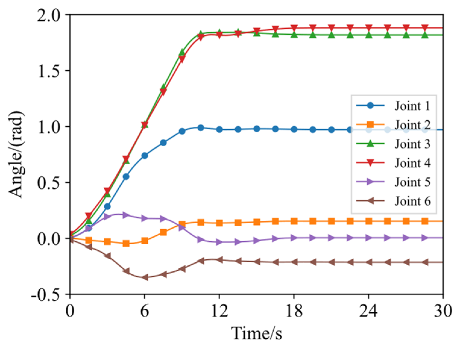
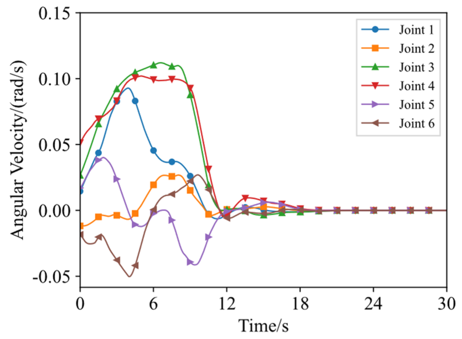
Figure 9 shows the variation curves of the arm joint angles under the optimal capture strategy, and Figure 10 shows the variation curves of the joint angular velocities. The horizontal axes represent the training steps during a task process. When the capture mechanism moves from the initial position to the capture position, the joint angular velocity gradually increases, but the maximum angular velocity does not exceed 0.15 rad/s. In the later stage of the capture process, the angular velocity gradually decreases and approaches 0 rad/s, effectively reducing the collision risk between the space manipulator and the target, preventing the target from escaping. After the manipulator approaches the capture position, all joints remain stable, allowing the end-effector to begin the capture task.
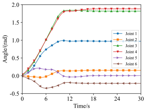
Figure 9.
Variation of arm joint angles.
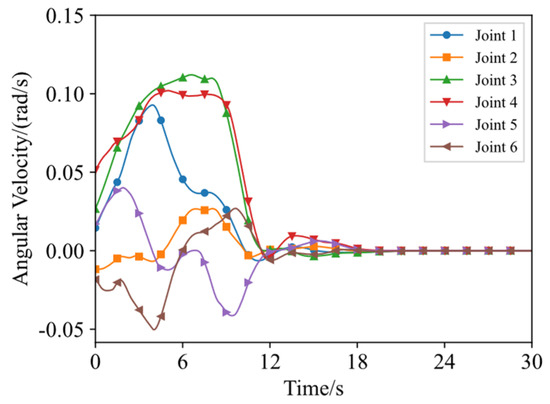
Figure 10.
Variation of arm joint angular velocities.
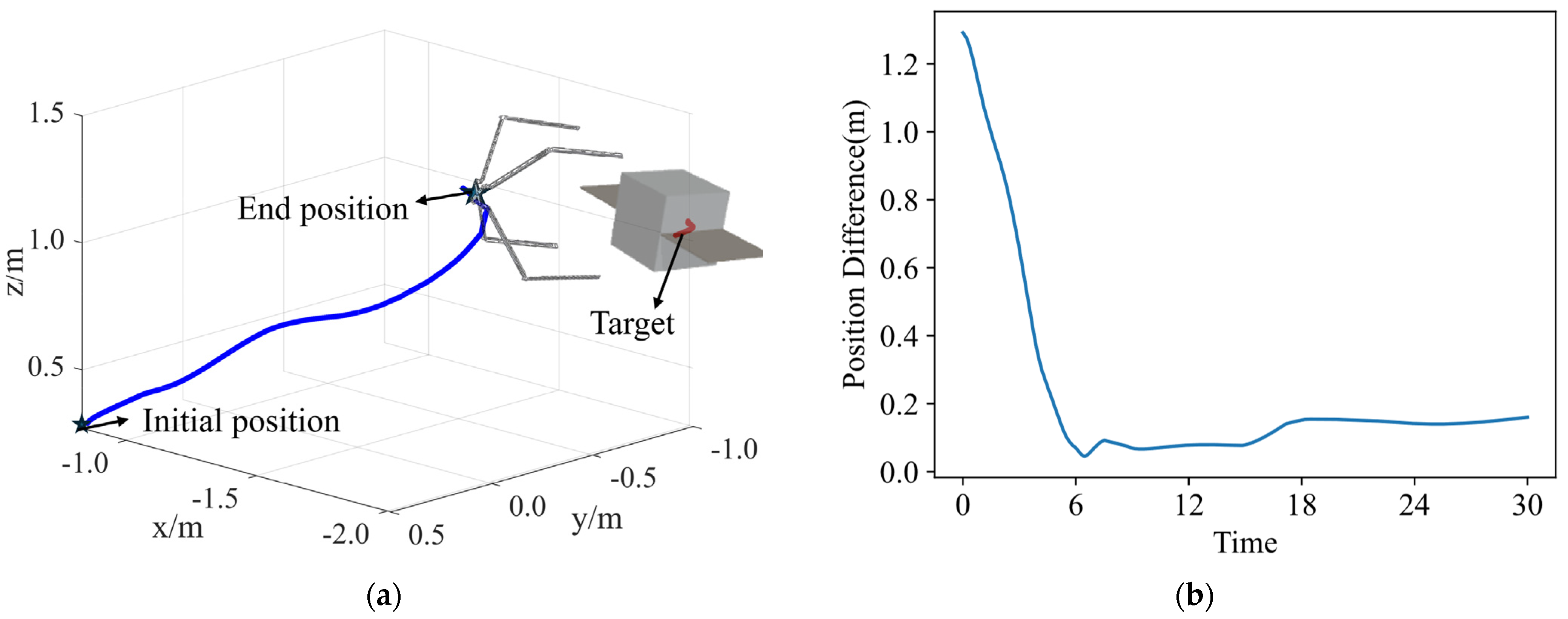
Figure 11a shows the spatial position changes of the end-effector capture center relative to the target during the entire target capture task, and Figure 11b shows the variation of the spatial distance between the end-effector and the target over time. The target’s position is [−2, −1, 1] with an attitude angle of (3.053, 1.240, −1.199). The initial position of the capture device is [−0.852, 0.503, 0.293]. At the end of the first stage of the capture process, the end-effector’s position is [−1.906, −0.083, 1.1418] with an attitude angle of (3.040, 1.235, −1.121). This indicates that in the world coordinate system, the x-axis and z-axis coordinates remain almost consistent, and the end-effector approaches the target along the y-axis, forming a suitable capture posture.
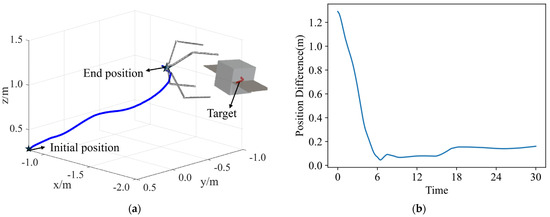
Figure 11.
Spatial distance between end-effector and target. (a) The position of the end-effector and target and (b) the variation of distance over time.
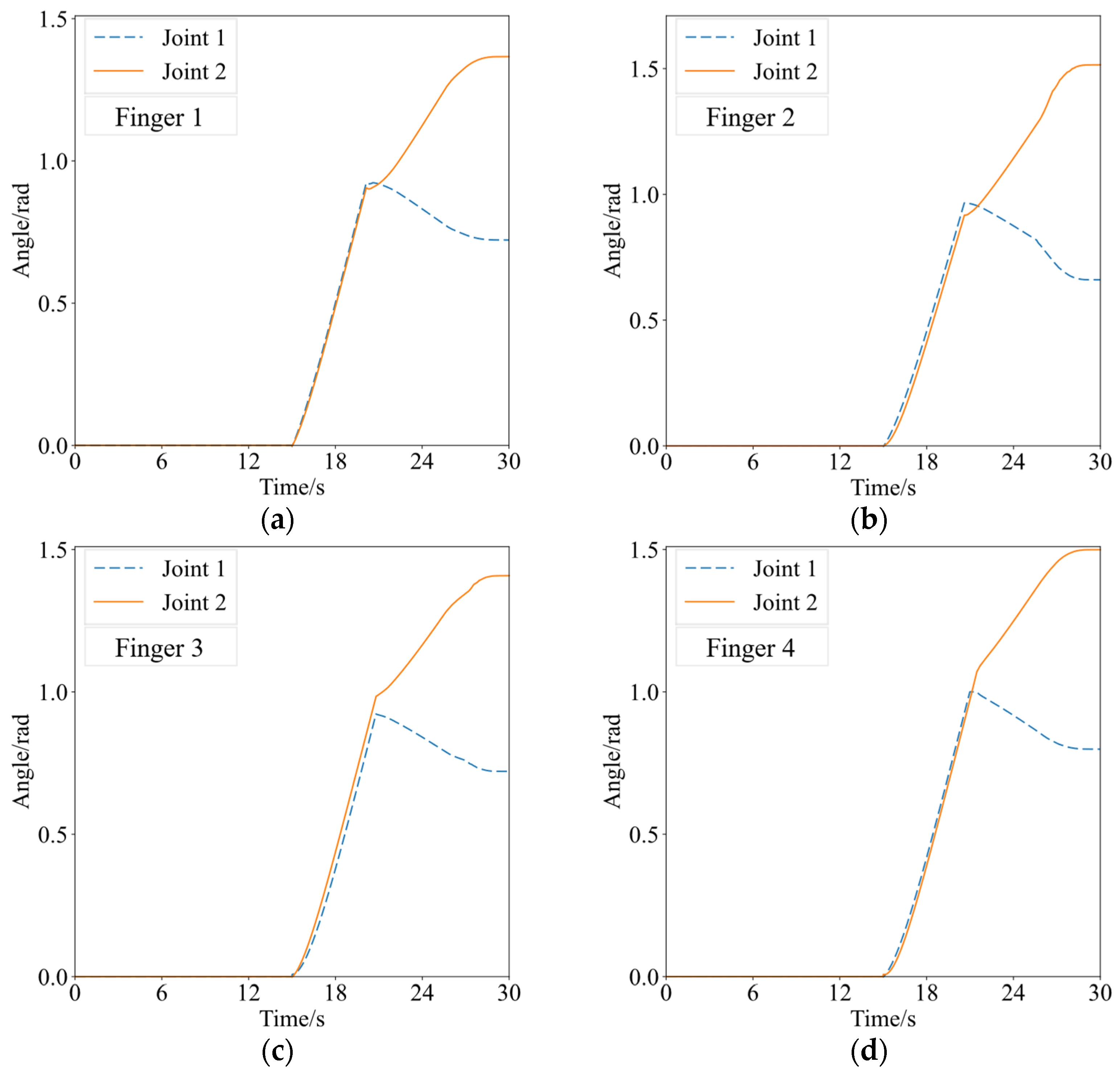
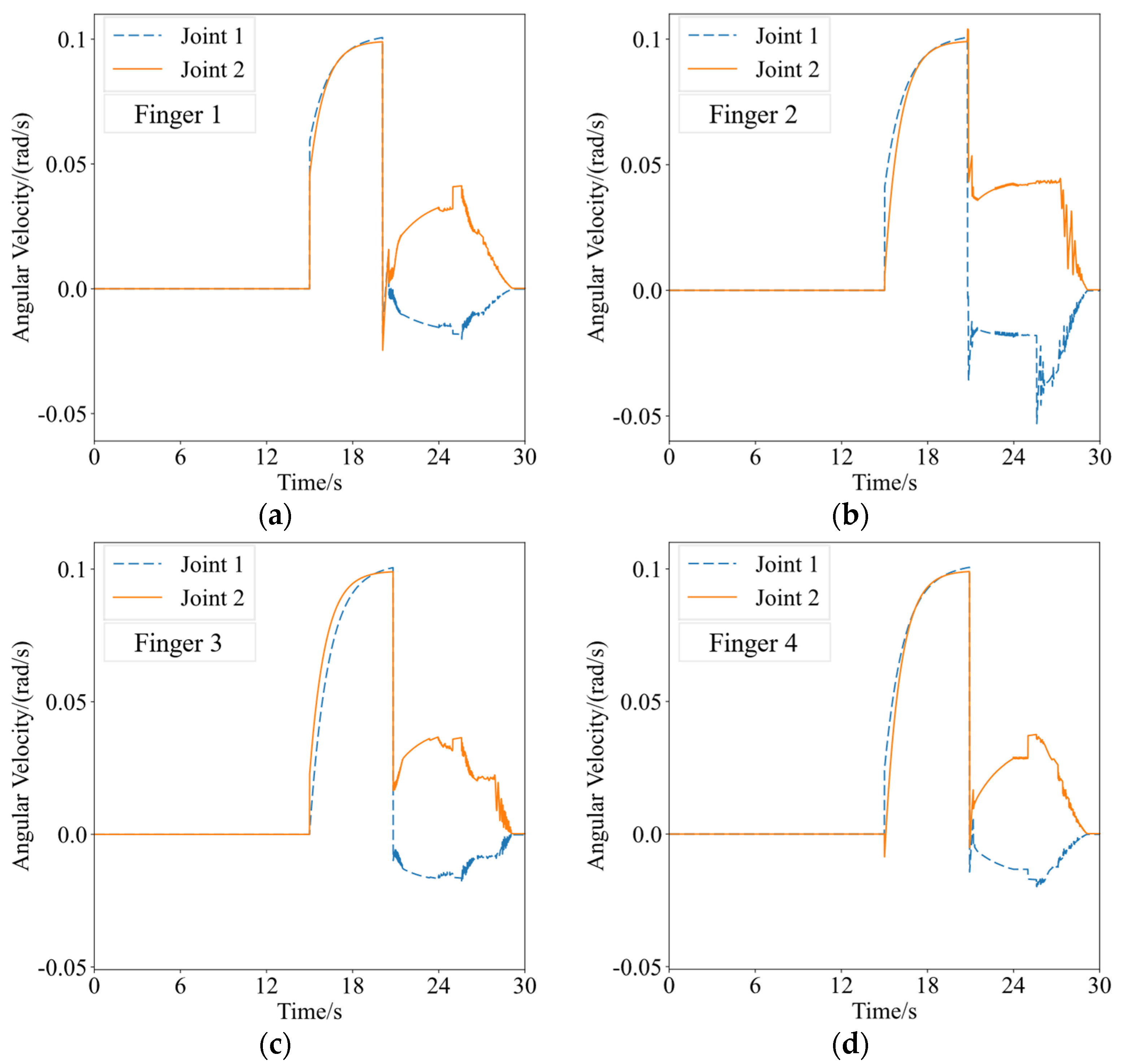
Figure 12 and Figure 13 illustrate the changes in the joint angles and angular velocities of the capture mechanism’s components under the optimal capture strategy. In Figure 12, the vertical axis represents the joint angles, while in Figure 13, the vertical axis represents the joint angular velocities. The horizontal axis in both figures indicates the time variation during a single task. “Finger i” (i = 1, 2, 3, 4) corresponds to the four fingers, and “Joint i” (i = 1, 2) corresponds to the first and second phalanges, respectively. As observed in Figure 12 and Figure 13, during the initial stage of the capture process, the two joints of each finger in the grasping mechanism accelerate simultaneously to close. When the angular velocity approaches the maximum speed limit, the acceleration gradually decreases to zero, stabilizing the angular velocity at approximately 0.1 rad/s. Around 20 s into the capture process, the capture mechanism makes contact with the target, with each segment of the fingers successively colliding with the target. The angle of the first segment of each finger decreases, while the angle of the second segment increases, drawing the target inward. Once the fingers have closed in to grip the target, the positions of the joints remain fixed, the joint angles stabilize without further change, and the joint angular velocities gradually decrease to zero. At this point, the entire process of capturing the non-cooperative target is complete.
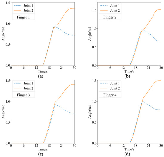
Figure 12.
Joint angle changes of the capture mechanism. (a) Finger 1; (b) finger 2; (c) finger 3; (d) finger 4.
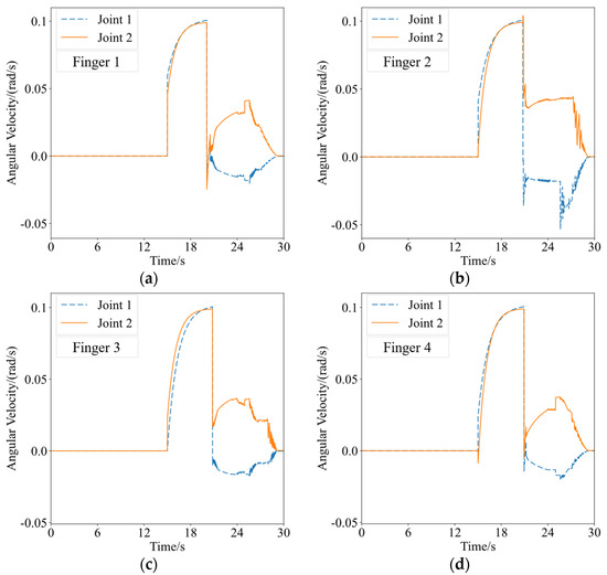
Figure 13.
Joint angular velocity changes of the capture mechanism. (a) Finger 1; (b) finger 2; (c) finger 3; (d) finger 4.
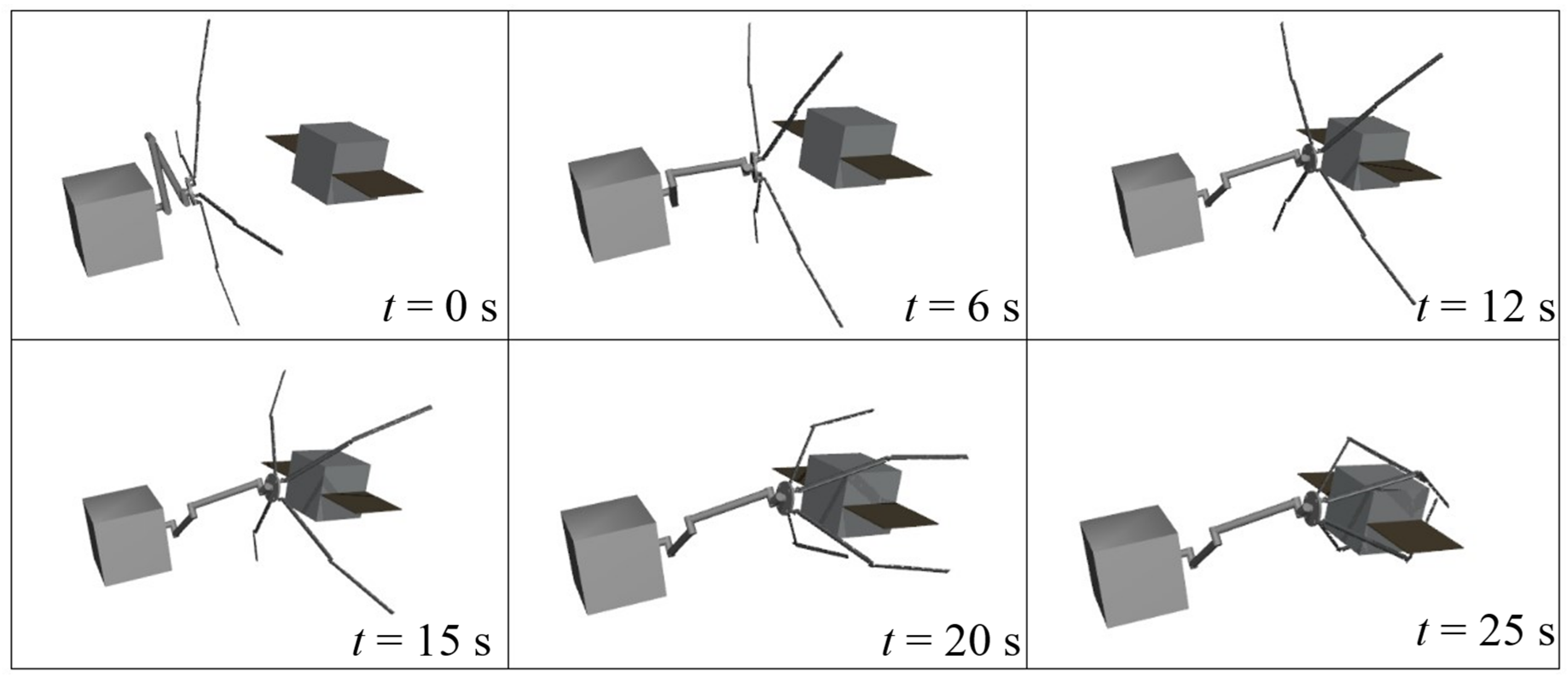
Figure 14 provides a visual simulation result of the space robot performing the target capture task. The robot’s base maintains a fixed posture and the space manipulator slowly moves toward the target. It stops at a small distance from the target, with the end-effector’s posture stable and appropriate. Finally, the end-effector’s fingers close, grasping and securing the target, thus completing the capture process.
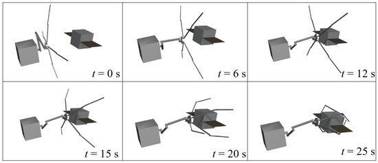
Figure 14.
Capture process diagram.
4.3. Multi-Angle Capture Simulation
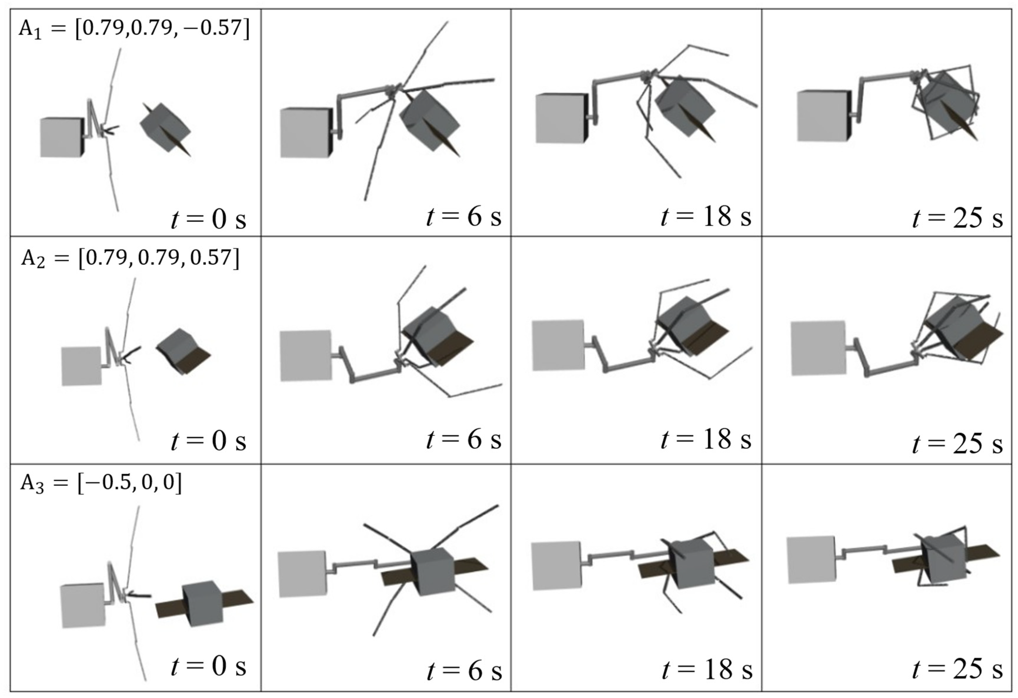
To verify the algorithm’s effectiveness, multi-angle capture simulations were designed. Considering the scenario where the manipulator’s end-effector approaches the target, it is necessary to ensure that the end-effector can approach the target with an appropriate grasping posture. Figure 15 shows the space robot capturing targets with different positions and postures within the capture range. The initial target postures are set to , , and . Based on the position and posture of the captured target, the space robot moves its manipulator to bring the end-effector to the appropriate capture point. The end-effector approaches the target accurately with a grasping posture without colliding with the target during the approach. The simulation results indicate that reasonable capture strategies can be obtained through reinforcement learning training for targets with different positions and postures, completing stable and reliable capture actions with good stability and feasibility.
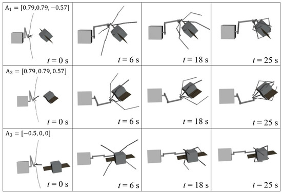
Figure 15.
Multi-angle capture process diagram.
4.4. Multi-Target Capture Simulation
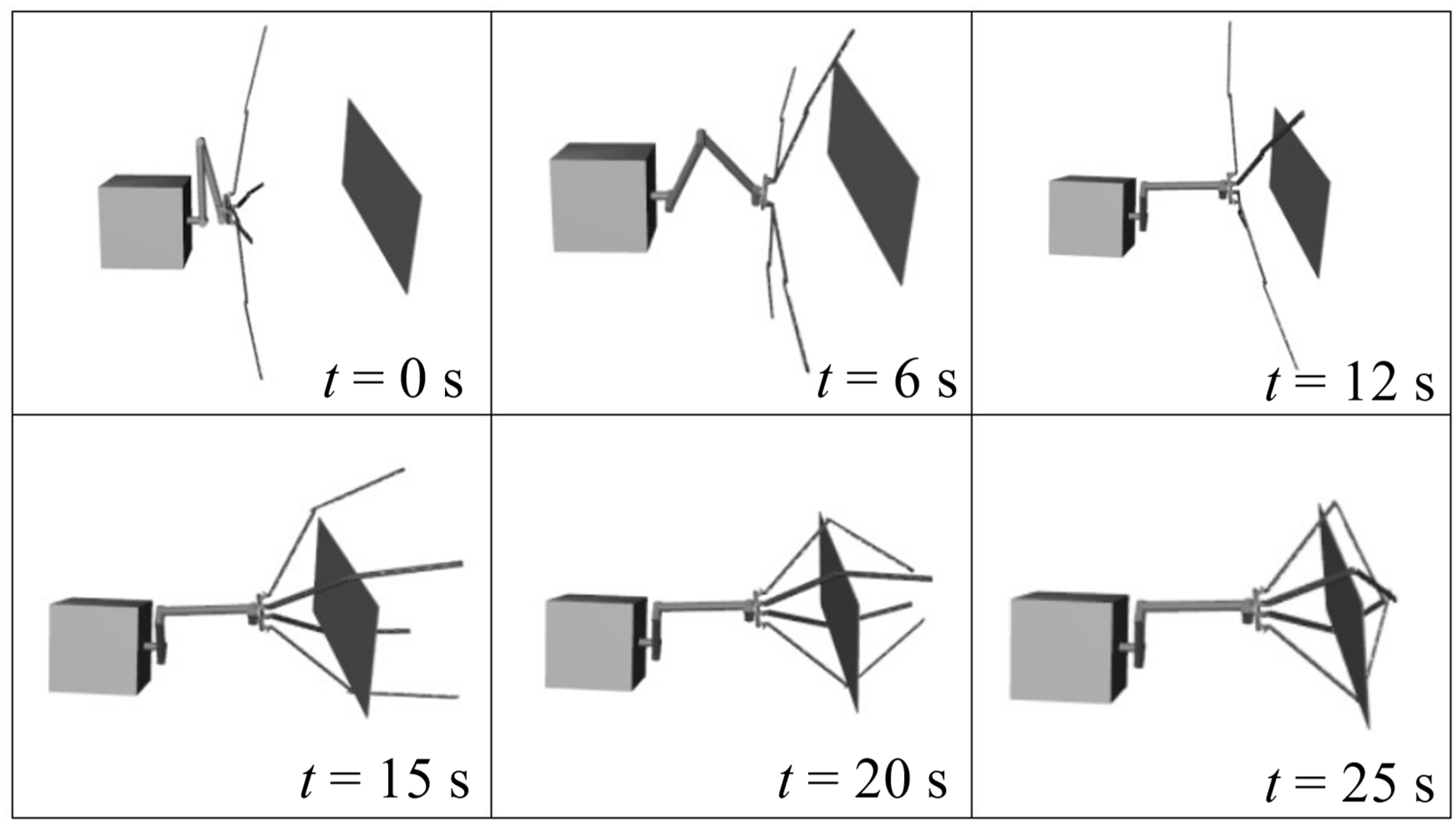
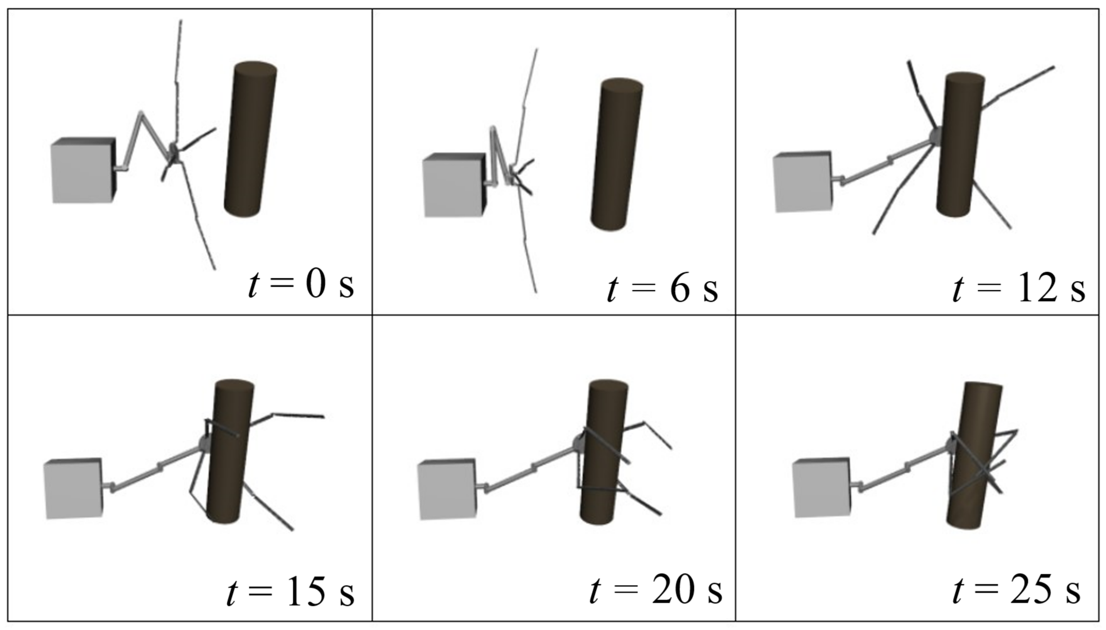
To verify the adaptability of the capture strategy, capture simulations were conducted for typical shapes of space debris, in addition to the failed satellite with solar panels. Figure 16 and Figure 17 show the capture processes for plate-shaped and rod-shaped debris, respectively. It can be seen that for different targets, during the first stage of capture, the end-effector moves to the appropriate capture point and approaches the target with a grasping posture. In the second stage, the end-effector closes, securing the target within the capture range. The fingers of the end-effector then close around the target, forming a reliable rigid connection.
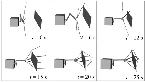
Figure 16.
Capture process for the plate-shaped target.
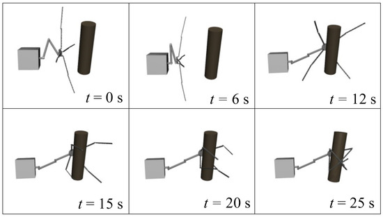
Figure 17.
Capture process for the rod-shaped target.
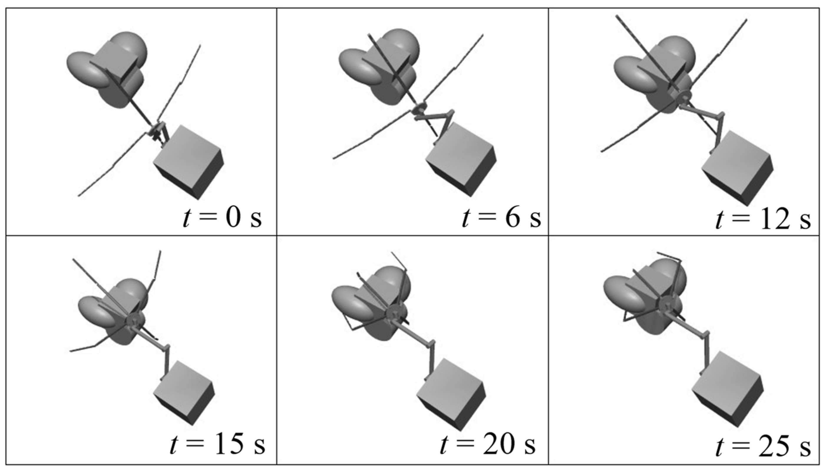
Figure 18 shows the capture process for an irregular combined target. In the first stage, the end-effector moves to the appropriate capture point. In the second stage, the four fingers of the end-effector start to close in a coordinated manner, adapting to the target’s outer contour. The fingers move synchronously, gradually fitting the target’s outer surface contour. This synchronous and coordinated movement ensures that each finger almost simultaneously contacts the target, thereby increasing the capture’s stability and success rate.
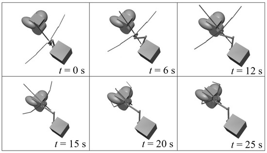
Figure 18.
Capture process for irregular target.
4.5. Capture Strategy Analysis
When capturing space non-cooperative targets, the capture strategy varies depending on the target type, as shown in Table 3. For targets with solar panels, the main body of the satellite is grasped, adjusting the posture of the fingers to ensure that the grasping force is evenly distributed on the satellite body. For plate-shaped targets, the four fingers of the end-effector are evenly distributed on the target’s edges, applying uniformly distributed force during closure to ensure capture stability and reliability. For rod-shaped targets, which typically have a high length-to-diameter ratio, it is essential to ensure the grasping point’s encapsulation and restraint force during capture. The four fingers close around the target, providing sufficient restraint to prevent the target from slipping during capture. For complex-shaped irregular satellites, the four fingers of the end-effector almost simultaneously contact the target during closure and then fit the target’s outer contour for capture and fixation. In summary, utilizing the multi-finger, multi-joint structure of the end-effector, efficient and reasonable capture actions can be performed for targets of different shapes.

Table 3.
Capture strategies for different targets.
5. Conclusions
To address the complexities of motion planning for space robots in the task of capturing non-cooperative targets in space, this study first established an “arm + claw” configuration for the space robot. Then, considering the motion planning of both position and posture, a capture posture planning network was constructed, and a capture strategy for non-cooperative space targets based on a reinforcement learning algorithm was proposed. Finally, the algorithm and model were tested through simulations on a simulation platform. The simulation results indicate that the capture strategy incorporating capture posture planning effectively accomplishes the capture of non-cooperative space targets. During the capture process, for targets with different positions and postures, the end-effector of the space robot approaches the target with an appropriate grasping posture and completes a stable capture action. The proposed capture strategy also performs high-quality tasks for targets of different shapes. This method effectively addresses the complex situations encountered in space environments, improving the success rate and stability of the robot in capturing non-cooperative targets.
Author Contributions
Conceptualization, Z.P. and C.W.; methodology, Z.P. and C.W.; software, Z.P.; validation, Z.P. and C.W.; formal analysis, Z.P. and C.W.; investigation, Z.P. and C.W.; resources, Z.P. and C.W.; data curation, Z.P. and C.W.; writing—original draft preparation, Z.P.; writing—review and editing, C.W.; visualization, Z.P.; supervision, C.W.; project administration, C.W.; funding acquisition, C.W. All authors have read and agreed to the published version of the manuscript.
Funding
This research received no external funding.
Data Availability Statement
The original contributions presented in the study are included in the article, further inquiries can be directed to the corresponding author.
Acknowledgments
The authors would like to thank the reviewers for their constructive comments and suggestions that have helped to improve this paper.
Conflicts of Interest
The authors declare no conflicts of interest.
References
- Flores-Abad, A.; Ma, O.; Pham, K.; Ulrich, S. A Review of Space Robotics Technologies for On-Orbit Servicing. Prog. Aerosp. Sci. 2014, 68, 1–26. [Google Scholar] [CrossRef]
- Li, W.-J.; Cheng, D.-Y.; Liu, X.-G.; Wang, Y.-B.; Shi, W.-H.; Tang, Z.-X.; Gao, F.; Zeng, F.-M.; Chai, H.-Y.; Luo, W.-B.; et al. On-Orbit Service (OOS) of Spacecraft: A Review of Engineering Developments. Prog. Aerosp. Sci. 2019, 108, 32–120. [Google Scholar] [CrossRef]
- Moghaddam, B.M.; Chhabra, R. On the Guidance, Navigation and Control of in-Orbit Space Robotic Missions: A Survey and Prospective Vision. Acta Astronaut. 2021, 184, 70–100. [Google Scholar] [CrossRef]
- Han, D.; Dong, G.; Huang, P.; Ma, Z. Capture and Detumbling Control for Active Debris Removal by a Dual-Arm Space Robot. Chin. J. Aeronaut. 2022, 35, 342–353. [Google Scholar] [CrossRef]
- Ma, S.; Liang, B.; Wang, T. Dynamic Analysis of a Hyper-Redundant Space Manipulator with a Complex Rope Network. Aerosp. Sci. Technol. 2020, 100, 105768. [Google Scholar] [CrossRef]
- Peng, J.; Xu, W.; Hu, Z.; Liang, B. A Trajectory Planning Method for Rapid Capturing an Unknown Space Tumbling Target. In Proceedings of the 2018 IEEE 8th Annual International Conference on CYBER Technology in Automation, Control, and Intelligent Systems (CYBER), Tianjin, China, 19–23 July 2018; pp. 230–235. [Google Scholar]
- She, Y.; Li, S.; Hu, J. Contact Dynamics and Relative Motion Estimation of Non-Cooperative Target with Unilateral Contact Constraint. Aerosp. Sci. Technol. 2020, 98, 105705. [Google Scholar] [CrossRef]
- Bualat, M.G.; Smith, T.; Smith, E.E.; Fong, T.; Wheeler, D. Astrobee: A New Tool for ISS Operations. In Proceedings of the 2018 SpaceOps Conference, Marseille, France, 28 May–1 June 2018. [Google Scholar]
- Yu, Z.; Liu, X.; Cai, G. Dynamics Modeling and Control of a 6-DOF Space Robot with Flexible Panels for Capturing a Free Floating Target. Acta Astronaut. 2016, 128, 560–572. [Google Scholar] [CrossRef]
- Cai, B.; Yue, C.; Wu, F.; Chen, X.; Geng, Y. A Grasp Planning Algorithm under Uneven Contact Point Distribution Scenario for Space Non-Cooperative Target Capture. Chin. J. Aeronaut. 2023, 36, 452–464. [Google Scholar] [CrossRef]
- Zhang, O.; Yao, W.; Du, D.; Wu, C.; Liu, J.; Wu, L.; Sun, Y. Trajectory Optimization and Tracking Control of Free-Flying Space Robots for Capturing Non-Cooperative Tumbling Objects. Aerosp. Sci. Technol. 2023, 143, 108718. [Google Scholar] [CrossRef]
- Aghili, F. A Prediction and Motion-Planning Scheme for Visually Guided Robotic Capturing of Free-Floating Tumbling Objects With Uncertain Dynamics. IEEE Trans. Robot. 2012, 28, 634–649. [Google Scholar] [CrossRef]
- Rembala, R.; Teti, F.; Couzin, P. Operations Concept for the Robotic Capture of Large Orbital Debris. Adv. Astronaut. Sci. 2012, 144, 111–120. [Google Scholar]
- Jayakody, H.S.; Shi, L.; Katupitiya, J.; Kinkaid, N. Robust Adaptive Coordination Controller for a Spacecraft Equipped with a Robotic Manipulator. J. Guid. Control Dyn. 2016, 39, 2699–2711. [Google Scholar] [CrossRef]
- Xu, L.; Hu, Q.; Zhang, Y. 2 Performance Control of Robot Manipulators with Kinematics, Dynamics and Actuator Uncertainties. Int. J. Robust. Nonlinear Control 2017, 27, 875–893. [Google Scholar] [CrossRef]
- Hu, Q.; Guo, C.; Zhang, Y.; Zhang, J. Recursive Decentralized Control for Robotic Manipulators. Aerosp. Sci. Technol. 2018, 76, 374–385. [Google Scholar] [CrossRef]
- Andrychowicz, O.M.; Baker, B.; Chociej, M.; Józefowicz, R.; McGrew, B.; Pachocki, J.; Petron, A.; Plappert, M.; Powell, G.; Ray, A.; et al. Learning Dexterous in-Hand Manipulation. Int. J. Robot. Res. 2019, 39, 3–20. [Google Scholar] [CrossRef]
- Fayjie, A.R.; Hossain, S.; Oualid, D.; Lee, D.J. Driverless Car: Autonomous Driving Using Deep Reinforcement Learning in Urban Environment. In Proceedings of the 2018 15th International Conference on Ubiquitous Robots (ur), Honolulu, HI, USA, 26–30 June 2018; pp. 896–901. [Google Scholar]
- He, Y.; Xing, L.; Chen, Y.; Pedrycz, W.; Wang, L.; Wu, G. A Generic Markov Decision Process Model and Reinforcement Learning Method for Scheduling Agile Earth Observation Satellites. IEEE Trans. Syst. Man Cybern. Syst. 2022, 52, 1463–1474. [Google Scholar] [CrossRef]
- Xu, D.; Hui, Z.; Liu, Y.; Chen, G. Morphing Control of a New Bionic Morphing UAV with Deep Reinforcement Learning. Aerosp. Sci. Technol. 2019, 92, 232–243. [Google Scholar] [CrossRef]
- Wang, S.; Zheng, X.; Cao, Y.; Zhang, T. A Multi-Target Trajectory Planning of a 6-DoF Free-Floating Space Robot via Reinforcement Learning. In Proceedings of the 2021 IEEE/RSJ International Conference on Intelligent Robots and Systems (IROS), Prague, Czech, 27 September–1 October 2021; pp. 3724–3730. [Google Scholar]
- Hu, X.; Huang, X.; Hu, T.; Shi, Z.; Hui, J. MRDDPG Algorithms for Path Planning of Free-Floating Space Robot. In Proceedings of the 2018 IEEE 9th International Conference on Software Engineering and Service Science (ICSESS), Beijing, China, 23–25 November 2018; pp. 1079–1082. [Google Scholar]
- Wang, S.; Cao, Y.; Zheng, X.; Zhang, T. An End-to-End Trajectory Planning Strategy for Free-Floating Space Robots. In Proceedings of the 2021 40th Chinese Control Conference (CCC), Shanghai, China, 26–28 July 2021; pp. 4236–4241. [Google Scholar]
- Yan, C.; Zhang, Q.; Liu, Z.; Wang, X.; Liang, B. Control of Free-Floating Space Robots to Capture Targets Using Soft Q-Learning. In Proceedings of the 2018 IEEE International Conference on Robotics and Biomimetics (ROBIO), Kuala Lumpur, Malaysia, 12–15 December 2018; pp. 654–660. [Google Scholar]
- Li, Y.; Li, D.; Zhu, W.; Sun, J.; Zhang, X.; Li, S. Constrained Motion Planning of 7-DOF Space Manipulator via Deep Reinforcement Learning Combined with Artificial Potential Field. Aerospace 2022, 9, 163. [Google Scholar] [CrossRef]
- Lei, W.; Fu, H.; Sun, G. Active Object Tracking of Free Floating Space Manipulators Based on Deep Reinforcement Learning. Adv. Space Res. 2022, 70, 3506–3519. [Google Scholar] [CrossRef]
- Wu, H.; Hu, Q.; Shi, Y.; Zheng, J.; Sun, K.; Wang, J. Space Manipulator Optimal Impedance Control Using Integral Reinforcement Learning. Aerosp. Sci. Technol. 2023, 139, 108388. [Google Scholar] [CrossRef]
- Cao, Y.; Wang, S.; Zheng, X.; Ma, W.; Xie, X.; Liu, L. Reinforcement Learning with Prior Policy Guidance for Motion Planning of Dual-Arm Free-Floating Space Robot. Aerosp. Sci. Technol. 2023, 136, 108098. [Google Scholar] [CrossRef]
- Wang, S.; Cao, Y.; Zheng, X.; Zhang, T. A Learning System for Motion Planning of Free-Float Dual-Arm Space Manipulator towards Non-Cooperative Object. Aerosp. Sci. Technol. 2022, 131, 107980. [Google Scholar] [CrossRef]
- Ma, B.; Jiang, Z.; Liu, Y.; Xie, Z. Advances in Space Robots for On-Orbit Servicing: A Comprehensive Review. Adv. Intell. Syst. 2023, 5, 2200397. [Google Scholar] [CrossRef]
- Kumar, A.; Sharma, R. Linguistic Lyapunov Reinforcement Learning Control for Robotic Manipulators. Neurocomputing 2018, 272, 84–95. [Google Scholar] [CrossRef]
- Lillicrap, T.P.; Hunt, J.J.; Pritzel, A.; Heess, N.; Erez, T.; Tassa, Y.; Silver, D.; Wierstra, D. Continuous Control with Deep Reinforcement Learning. arXiv 2019, arXiv:1509.02971. [Google Scholar]
- Haarnoja, T.; Zhou, A.; Abbeel, P.; Levine, S. Soft Actor-Critic: Off-Policy Maximum Entropy Deep Reinforcement Learning with a Stochastic Actor. In Proceedings of the 35th International Conference on Machine Learning, PMLR, Stockholm, Sweden, 10–15 July 2018; pp. 1861–1870. [Google Scholar]
- Ciosek, K.; Vuong, Q.; Loftin, R.; Hofmann, K. Better Exploration with Optimistic Actor Critic. In Advances in Neural Information Processing Systems; Curran Associates, Inc.: New York, NY, USA, 2019; Volume 32. [Google Scholar]
Disclaimer/Publisher’s Note: The statements, opinions and data contained in all publications are solely those of the individual author(s) and contributor(s) and not of MDPI and/or the editor(s). MDPI and/or the editor(s) disclaim responsibility for any injury to people or property resulting from any ideas, methods, instructions or products referred to in the content. |
© 2024 by the authors. Licensee MDPI, Basel, Switzerland. This article is an open access article distributed under the terms and conditions of the Creative Commons Attribution (CC BY) license (https://creativecommons.org/licenses/by/4.0/).

