Article

An Improved Comprehensive Atomization Model for Pressure Swirl Atomizers

1
Institute for Energy Research, Jiangsu University, Zhenjiang 212013, China
2
Research Institute of Aero-Engine, Beihang University, Beijing 100191, China
3
School of Energy Engineering, Zhejiang University, Hangzhou 310013, China
4
School of Energy and Power Engineering, Beihang University, Beijing 100191, China
*
Author to whom correspondence should be addressed.
Aerospace 2024, 11(8), 658; https://doi.org/10.3390/aerospace11080658
Submission received: 17 July 2024 / Revised: 6 August 2024 / Accepted: 8 August 2024 / Published: 12 August 2024
(This article belongs to the Section Aeronautics)

Abstract

:
This study presents an improved comprehensive atomization model for a pressure swirl atomizer. The model integrates internal flow predictions, linear instability analysis of a swirling annular liquid sheet, primary atomization sub-model, and droplet velocity sub-model. Measurement data combined with the inviscid theory model predict the internal flow, providing liquid sheet velocity and thickness at the atomizer outlet. The dispersion relation of surface disturbances is obtained through linear instability analysis. A primary breakup predictive model for particle size distribution is constructed based on the wavelength and growth rate within the full unstable wavenumber range of the dispersion relation. Assuming uniform circumferential distribution and a normal distribution of spray angles, the droplet velocity is assigned according to the liquid sheet velocity. The model is implemented into Eulerian–Lagrangian simulations as initial conditions for discrete phase droplets to simulate the spray field. Results show the model can accurately predict the Sauter mean diameter with an error of less than 6% and effectively predicts the spray structure and spray cone angle. The dependency of the model on its parameters is also studied, determining that the values of the ligament constant and dispersion angle have an obvious impact on the prediction of Sauter mean diameter and spray structure.

1. Introduction

Pressure swirl atomizers (PSA) have the advantages of high reliability, low cost, and satisfying atomization performance, and therefore, they have been widely used in various fields such as aircraft engines, rocket engines, pharmaceuticals, cooling, etc., [1,2,3,4]. For these applications, thanks to the improvement in computing power and the development of computational fluid dynamics (CFD), numerical simulations can be widely used to reduce design costs and enhance design efficiency [5]. However, when simulating the spray field of a PSA, the biggest obstacle is the difficulty in describing the initial conditions of the spray field, specifically the droplet size and velocity produced by the primary atomization of the pressure swirl atomizer, which indicates a lack of development in atomization models [6]. This necessitates the development of efficient atomization models for PSAs.
The atomization models for pressure swirl atomizers have been developed for decades and can be categorized based on their formulation principles into empirical models, semi-empirical models, and comprehensive models. Empirical models are empirical correlations obtained by fitting experimental data. Previous studies have developed empirical correlations for the Sauter mean diameter (SMD) of the spray produced by PSAs regarding pressure drops, physical properties, and structure parameters [7,8,9]. Readers interested in these empirical correlations can refer to [10,11].
Compared to empirical models, semi-empirical models combine theoretical derivations with fitting experimental data in their construction process, which helps improve the accuracy. For example, Wang and Lefebvre [12] proposed that the atomization process of PSAs can be divided into two stages. In the first stage, the combined action of hydraulic and aerodynamic forces causes surface instability in the liquid sheet. In the second stage, surface instability causes the liquid sheet to break into liquid ligaments, which further break into droplets. The overall SMD of the spray field is assumed to be the sum of the SMDs from both stages. In another work by Lefebvre [13], the SMD prediction is conducted based on the flow analysis inside the exit orifice of the PSA combined with experimental data. Previous studies [14,15,16,17,18] utilize the linear instability of a planar liquid sheet to predict the primary atomization of the liquid sheet for droplet size prediction. Compared to empirical models, the advantage of the semi-empirical atomization models is that they expand the applicability and improve the accuracy of the model by incorporating theoretical analysis. However, like empirical models, they can only predict the characteristic droplet size and cannot be used as initial conditions for the spray field in CFD simulations.
In comparison, comprehensive atomization models combine the prediction of internal flow within the pressure swirl atomizer [19,20], modeling of the primary atomization process of the liquid sheet [14,21,22], and the description of droplet size and velocity distribution [23,24]. These models have the widest applicability and the strongest predictive capabilities. The most well-known comprehensive atomization model is the Linearized Instability Sheet Atomization (LISA) model by Schmidt et al. [25], which is widely used in commercial CFD software. This model uses empirical models to predict nozzle internal flow and employs linear instability analysis of a two-dimensional planar liquid sheet moving in still air to construct the liquid sheet breakup model. However, it does not address the modeling of droplet size and velocity distributions. Using this model, it is possible to simulate spray penetration distance and SMD values. Moon et al. [26] used theoretical analysis that considers viscous losses to predict the internal flow. They then used the results of linear instability analysis of a planar liquid sheet to predict the average droplet diameter produced by the liquid sheet breakup. The droplet size distribution was set to a Rosin–Rammler distribution. The predicted results were used as initial conditions for the discrete phase droplets and imported into the simulation software KIVA. Results showed that the model could predict the liquid sheet breakup length, SMD, and spray distribution of the PSA.
In summary, most of the existing comprehensive atomization models do not incorporate the linear instability analysis of a swirling annular liquid sheet to predict its breakup, which is more consistent with actual conditions, and lacks theoretical predictions of the droplet size distribution. These factors affect the predictive capability of comprehensive atomization models. Therefore, this study aims to predict the primary atomization for pressure swirl atomizers based on the linear instability analysis of a swirling annular liquid sheet and to predict droplet size distribution based on the wavelength and wave growth rate within the entire unstable wavenumber range, thereby improving the comprehensive atomization model for PSAs. The formulation details of the improved comprehensive atomization model will be provided in the next section, followed by the method for implementing the model into commercial software. Then, the experimental methods used to validate the model will be described. Finally, the accuracy of the model will be verified by comparing simulation results with experimental results, and the effects of model parameter values on the spray prediction results will be quantified and discussed.

2. Model Formulation

In a typical pressure swirl atomizer, as shown in Figure 1, the working fluid flows into the swirl chamber through tangential holes or slots under pressure, forming a swirling flow. Due to this swirling flow, a low-pressure region forms at the center of the swirl chamber, and air is drawn into the swirl chamber from the atomizer outlet to form a gas core [27]. This gas core extends from the atomizer outlet to the rear of the swirl chamber. The fluid develops from an annular liquid sheet into a hollow conical liquid sheet under the action of centrifugal force as it exits the atomizer outlet [28]. Due to the velocity difference between the gas phase and the liquid sheet, unstable waves are generated on the surface of the liquid sheet. As the liquid sheet moves downstream, the amplitude of the unstable waves increases, leading to the breakup of the liquid sheet into liquid ligaments. These ligaments further break up into droplets due to instability. The droplets can undergo secondary atomization, breaking into even smaller droplets [29].
The above primary atomization process of a pressure swirl atomizer will be described by an improved comprehensive atomization model in this work which consists of four sub-models: the internal flow sub-model, the liquid sheet instability sub-model, the primary atomization sub-model, and the droplet velocity sub-model. Specifically, the internal flow sub-model predicts the liquid sheet thickness and velocity at the atomizer exit under given conditions, which serve as input conditions for the liquid sheet instability sub-model. Based on the instability sub-model, the linear instability of the swirling annular liquid sheet is predicted. Primary atomization is predicted based on the linear instability of the liquid sheet by the corresponding sub-model. Finally, the droplet velocity sub-model is used to set the velocities for primary atomization droplets. The following subsections will introduce each of the four sub-models in detail.

2.1. Internal Flow Sub-Model

The inputs for the internal flow sub-model include the atomizer exit diameter D o , the spray half-angle θ , and the discharge coefficient C d . The internal flow sub-model predicts the liquid sheet thickness and velocity at the atomizer exit based on these data.
The internal flow of this type of atomizer is predicted using an inviscid theoretical model [30] combined with experimental data. The inviscid theoretical model provides the following relationship between the discharge coefficient C d and the liquid sheet area coefficient ψ :
C d = ψ 3 2 ψ
The liquid sheet area coefficient represents the ratio of the area occupied by the liquid sheet to the total area at the atomizer outlet cross-section. Geometrically, ψ = 1 ( d a / D o ) 2 as show in Figure 1. It can be calculated using the C d obtained from experiments using Equation (1). Subsequently, the air core diameter d a at the atomizer exit, as shown in Figure 1, can be calculated as:
d a = D o 1 ψ
The thickness of the liquid sheet at the atomizer exit is as follows:
t f = ( D o d a ) / 2 = D o ( 1 1 ψ ) / 2 .
Then the axial and tangential velocities ( U ¯ l , W ¯ l ) at the atomizer exit can be calculated using the following equations:
U ¯ l = 4 Q ˙ π ( D o 2 d a 2 ) ,
W ¯ l = U ¯ l tan ( θ ) .
Through the above steps, the liquid sheet configuration ( D a , t f ) and the liquid sheet velocity components U ¯ l and W ¯ l at the atomizer exit are determined. We note that the present approach of using an inviscid model combined with experimental data to predict the liquid sheet thickness at the nozzle exit is straightforward and easy to implement. But the prediction of internal flow can be improved using a viscous model, such as the model of Khavkin [31], Bazarov [32], and Ronceros et al. [33]. Due to the modular design of the comprehensive atomization model, the viscous internal flow model can be easily integrated into it.

2.2. Liquid Sheet Instability Sub-Model

2.2.1. Problem Formulation

Linear instability analysis provides the relationship between the wavelength of infinitesimal disturbances on the liquid sheet surface and the wave growth rate, known as the dispersion relation, which is used to predict the primary atomization [34].
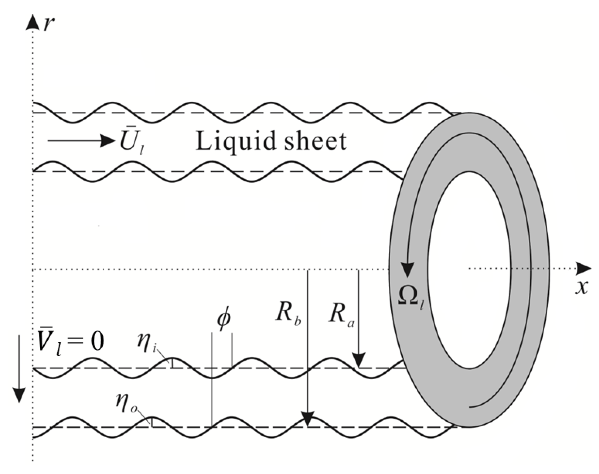
In the linear instability analysis, the conical liquid sheet emanating from the pressure swirl atomizer is modeled as an annular liquid sheet [35] shown in Figure 2. Assuming that the outer diameter of the annular liquid sheet is the same as the atomizer exit diameter D o , and the inner diameter is the same as the gas core diameter d a at the atomizer exit, the inner and outer radii of the annular liquid sheet are denoted as R a and R b , respectively. Here, only the swirling and axial motions of the annular liquid sheet in stationary air are considered [36]. The radial velocity V ¯ l of the liquid sheet is assumed as zero. The axial and tangential velocities at the steady state adopt the predicted values at the atomizer exit using the internal flow model. Besides, the effect of gravity is not considered, and the viscosity and compressibility of the gas phase are neglected.
Hence, the governing equations for such a flow are as follows:
· V j = 0 ,
V j t + V j · V j = 1 ρ j p j + ν j 2 V j .
where the subscript j = i , l, and o correspond to the inner gas phase, liquid sheet, and outer gas phase, respectively.

2.2.2. Governing Equations

To obtain the linearized disturbance governing equations, we decompose the instantaneous velocity and pressure in the governing equations into mean (denoted by overbar) and disturbance components (denoted by prime symbol):
U j = U ¯ j + u j , V j = v j , W j = W ¯ j + w j , p j = p ¯ j + p j .
Afterwards, we substitute the above decomposition into the governing equations, then expand, remove the mean quantities and second-order small terms, and retain the first-order small terms. This is the linearization treatment. After linearization, a normal mode expansion is performed on the disturbance quantities:
[ u j , v j , w j , p j ] = [ U ¯ l u ^ j ( r ) , U ¯ l v ^ j ( r ) , U ¯ l w ^ j ( r ) , ρ l U ¯ l 2 p ^ j ( r ) ] e i ( k x + n θ ω t ) ,
and the equations are made dimensionless (denoted by a star symbol). The scales for length, time, and pressure terms used in the nondimensionalization treatment are R b , R b / U ¯ , and ρ l U ¯ 2 / 2 , respectively. For the temporal linear instability analysis used here, axial wave number k and azimuthal wave number n are real, while wave frequency ω is complex with its real part ω r being the disturbance frequency and its imaginary part ω i being the wave growth rate of disturbance.
Through the above process, the dimensionless disturbance governing equations are obtained:
d v ^ l d r + v ^ l r + i n w ^ l r + i k u ^ l = 0 ,
u ^ l ( i k i ω + i n We s l We l ) = i k p ^ l + 1 Re l [ d 2 u ^ l d r 2 + d u ^ l r d r n 2 u ^ l r 2 k 2 u ^ l ] ,
v ^ l ( i k i ω + i n We s l We l ) 2 w ^ l We s l We l = d p ^ l d r + 1 Re l [ d 2 v ^ l d r 2 + d v ^ l r d r v ^ l ( 1 + n 2 + k 2 r 2 ) 2 n 2 w ^ l r 2 ] ,
w ^ l ( i k i ω + i n We s l We l ) + 2 v ^ l We s l We l = i n p ^ l r + 1 Re l [ d 2 w ^ l d r 2 + d w ^ l r d r w ^ l ( 1 + n 2 + k 2 r 2 ) + 2 n 2 v ^ l r 2 ] ,
for the liquid phase, and
d v ^ j d r + v ^ j r + i n w ^ j r + i k u ^ j = 0 ,
u ^ j ( i ω ) = i k p ^ j g j ,
v ^ j ( i ω ) = 1 g j d p ^ j d r ,
w ^ j ( i ω ) = i n g j p ^ j r ,
for the gas phase ( j = i and o).
In Equations (10)–(17), dimensionless parameters are defined as:
k = k R b , ω = ω R b U ¯ l , g i = ρ i ρ l , g o = ρ o ρ l , Re l = U ¯ l R b ν l , We l = ρ l U ¯ l 2 R b σ , We s l = ρ l Ω l 2 R b 3 σ .

2.2.3. Boundary Conditions

The governing equations are constrained by kinematic and dynamic boundary conditions at both the inner and outer interfaces of the annular liquid sheet. The physical meaning of the kinematic boundary conditions is that fluid particles on the interface will always remain on the interface which is given as:
d F i / o d t = F i / o t + V · F i / o = 0 .
The dynamic boundary conditions are as follows:
r r ( W l r ) + 1 r V l θ = 0 ,
U l r + V l z = 0 ,
p l + ρ l R b / a Ω l 2 η o / i 2 μ V l r = p o / i + ( · n o / i ) σ ,
with the first two equations representing the tangential stress balance on the interface, the last one representing the normal stress balance on the interface, and Ω l = W ¯ l / R b the swirling strength of the liquid sheet.
In Equations (18)–(21), F i / o represents the disturbed inner and outer interfaces which are given as
F i ( t , r , θ , x ) = r R a η i ( t , θ , x ) ,
F o ( t , r , θ , x ) = r R b η o ( t , θ , x ) ,
where η i / o ( t , θ , x ) represents the radial displacements of the perturbed interfaces from their equilibrium positions R a and R b . A normal mode expansion can also be performed on them as follows:
η i ( t , θ , x ) = R b η ^ i e i ( k x + n θ ω t ) ,
η o ( t , θ , x ) = R b η ^ o e i ( k x + n θ ω t + ϕ ) ,
where ϕ is the phase difference between two interfaces.
After applying the same linearization, nondimensionalization, and normal mode expansion to the boundary conditions as conducted for the governing equations, the kinematic and dynamic boundary conditions for the nondimensional disturbance amplitude can be obtained:
v ^ l ( h ) = ( i n We s l / We l + i k i ω ) η ^ i ,
v ^ l ( 1 ) = ( i n We s l / We l + i k i ω ) η ^ o e i ϕ ,
v ^ i ( h ) = ( i ω ) η ^ i ,
v ^ o ( 1 ) = ( i ω ) η ^ o e i ϕ ,
for the kinematic boundary conditions, and
h d w ^ l d r | r = h + i n v ^ l ( h ) w ^ l ( h ) = 0 ,
d u ^ l d r | r = h + i k v ^ l ( h ) = 0 ,
p ^ l ( h ) p ^ i ( h ) = ( 1 n 2 We l h 2 k 2 We l h We s l We l ) η ^ i + 2 Re l d v ^ l d r | r = h .
d w ^ l d r | r = 1 + i n v ^ l ( 1 ) w ^ l ( 1 ) = 0 ,
d u ^ l d r | r = 1 + i k v ^ l ( 1 ) = 0 ,
p ^ l ( 1 ) p ^ o ( 1 ) = ( n 2 1 We l + k 2 We l We s l We l ) η ^ o e i ϕ + 2 Re l d v ^ l d r | r = 1 .
for the dynamic boundary conditions, with h = R a / R b .

2.2.4. Formulation and Solution of the Dispersion Relation

After obtaining the governing equations and boundary conditions for the disturbance quantities, the problem lies in solving the dispersion relation from them.
First, the disturbance amplitudes of the pressure in the gas phase at the interfaces are obtained using the governing equations and boundary conditions:
p ^ i ( h ) = ω 2 g i I n ( k h ) k I n + 1 ( k h ) n I n ( k h ) / h η ^ i ,
p ^ o ( 1 ) = ω 2 g o K n ( k ) k K n + 1 ( k ) n K n ( k ) η ^ o e i ϕ ,
where I n and K n are the first and second types of modified Bessel functions, respectively.
By substituting the above two equations into the boundary conditions, a system of ordinary differential equations (ODE) containing only the liquid phase disturbance amplitude can be derived, with the complex frequency ω being the eigenvalue of this system. In this study, to avoid complex mathematical operations, Chebyshev expansion and collocation methods are used to numerically solve the dispersion relation, as detailed in Ref. [34]. By using Chebyshev expansion and collocation, the following system of equations is obtained.
A x = ω 2 B 2 x + ω B 1 x ,
with
x = ( u ^ l ( τ 0 ) , , u ^ l ( τ N ) , v ^ l ( τ 0 ) , , v ^ l ( τ N ) , w ^ l ( τ 0 ) , , w ^ l ( τ N ) )
where collocation points τ n = cos ( j π / N c ) , j = 0 , 1 , , N c with N c being the number of collocation points. The value of N c should be chosen such that the solution of the dispersion relation is independent of the value of N c .
For this system of equations, given a series of dimensionless wave numbers k , numerically solving for the eigenvalues of the system forms the dependency relationship between k and the complex frequency ω , i.e., the dispersion relation.

2.3. Primary Atomization Sub-Model

In the primary atomization model, it is considered that the growth of surface waves on the liquid sheet leads to its breakup. For a disturbance wave with axial wave number k, it is assumed that the diameter of the ligaments formed by the breakup of the liquid sheet is proportional to the wavelength of the disturbance, with the proportionality constant denoted as ligament constant, C L :
d L = C L × 2 π k
Further, the diameter of the droplets formed by the breakup of the ligaments has the following relationship with the diameter of the ligaments [14]:
d D = 1.88 d L ( 1 + 3 Oh ) 1 / 6
with Oh being the Ohnesorge number.
We adopted the assumption made by Liu et al. [37] that the mass flow rate m ˙ ( λ ) of the liquid sheet broken by a disturbance wave with axial wavenumber k over a unit wavelength length is proportional to its wavelength and inversely proportional to the corresponding breakup time of the liquid sheet:
m ˙ ( λ ) d λ = ρ l λ τ b d λ
where τ b is inversely proportional to the growth rate of the disturbance wave, but the proportionality constant does not affect the prediction results of the particle size distribution.
Then, for a disturbance wave with axial wave number k, the corresponding mass flow rate ratio Y l i g ( k ) for the breakup of the liquid sheet is as follows:
Y l i g ( k ) = m ˙ ( k ) i = 1 i = n k m ˙ ( k i )
The number of droplets produced per unit time corresponding to the wavenumber k and the resulting ligament diameter d D is as follows:
n d r o p l e t ( k ) = 6 m ˙ Y l i g ( k ) ρ l π d D ( k ) 3
The droplet size distribution of primary atomization can be predicted through the unstable wavenumber range and corresponding wave growth rates provided by the above equation and linear instability analysis.

2.4. Droplet Velocity Sub-Model

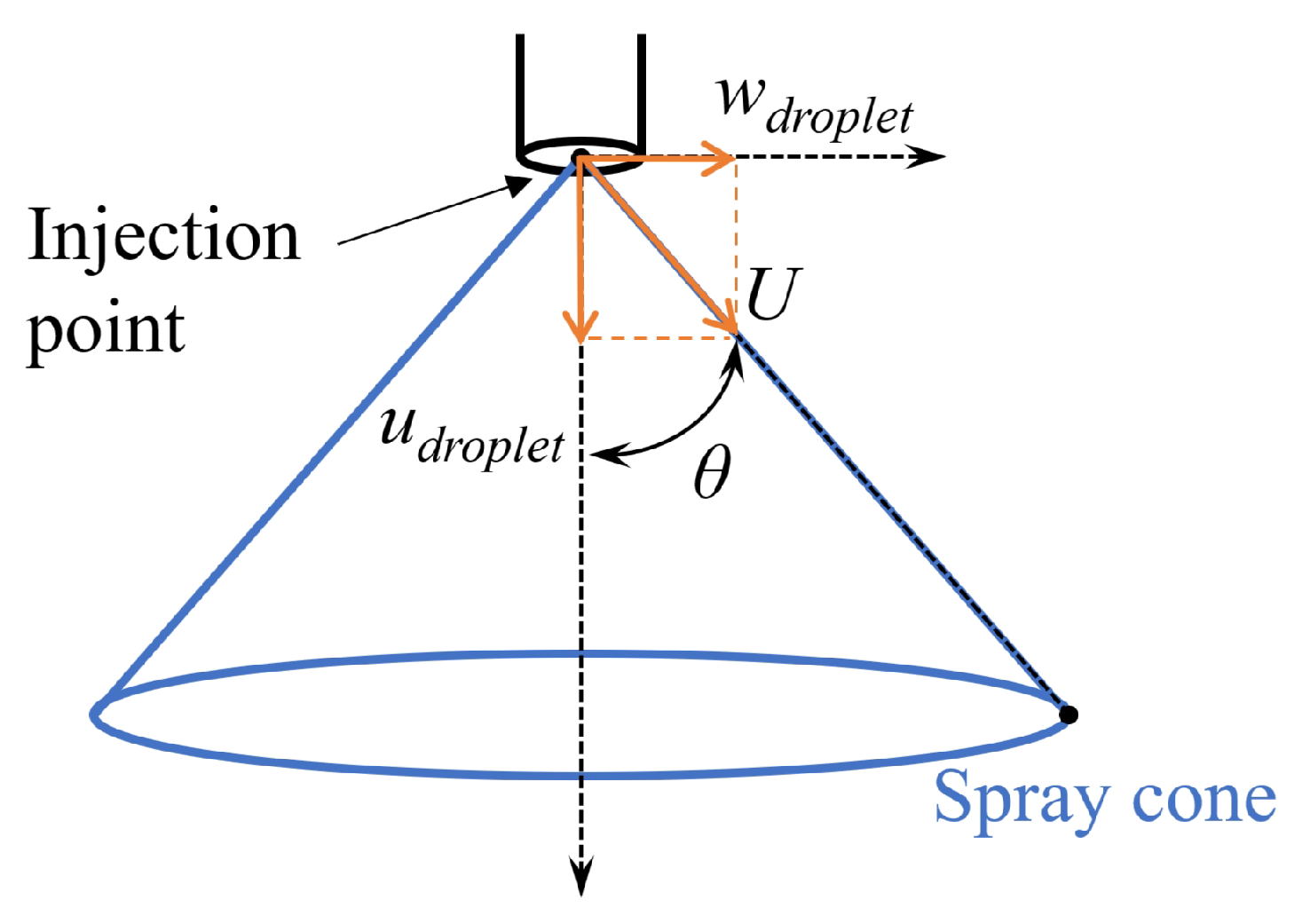
In this study, it is assumed that the droplet size distribution and velocity distribution are independent and uncorrelated. It is further assumed that droplets of different sizes have the same velocity magnitude. At the atomizer exit, it is assumed that the droplets only have axial and tangential velocities, with the radial velocity being zero. Given that the total velocity magnitude of droplets at the atomizer exit is denoted by U. Then the axial velocity of the droplets in the cylindrical coordinate system can be calculated as:
u d r o p l e t = U cos θ ,
and the tangential velocity in the cylindrical coordinate system is as follows:
w d r o p l e t = U sin θ
where θ is the half-cone angle of the spray. This velocity decomposition is shown in Figure 3.
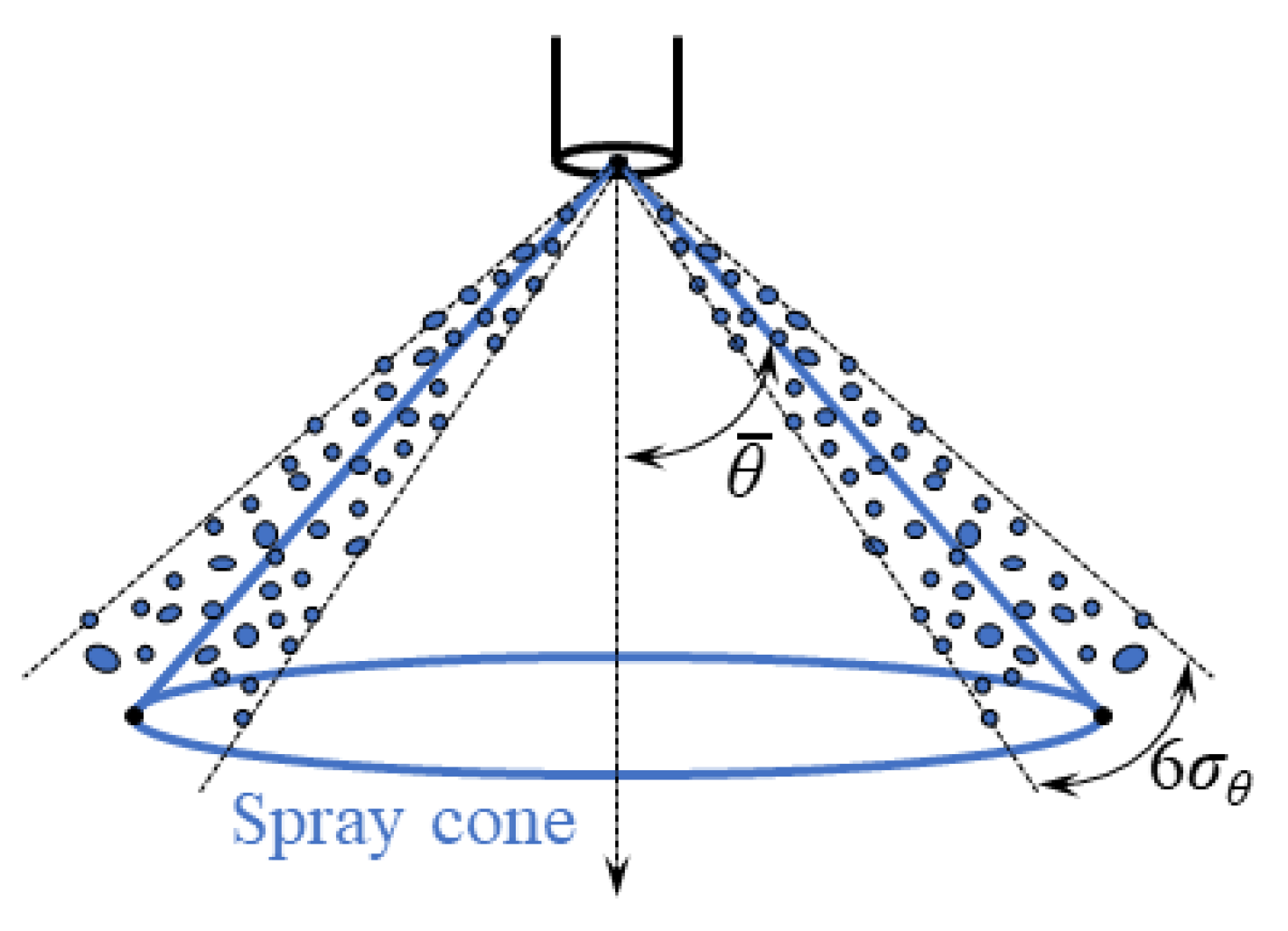
For a real spray, droplets do not move perfectly along the direction of the nominal spray cone angle of the atomizer; some droplets deviate from the direction of the nominal spray cone angle. Therefore, a dispersion angle needs to be specified to set the deviation degree between the movement angles of the droplet group and the nominal spray cone angle. We assume that the actual spray cone angle of droplet movement follows a normal distribution, i.e., the probability density function (Pdf) of θ is as follows:
P d f ( θ ) = 1 2 π σ θ exp ( θ θ ¯ ) 2 2 σ θ 2
where θ ¯ is the nominal half-cone angle of the nozzle. The standard deviation σ θ of the normal distribution given in Equation (47) is referred to as the spray dispersion angle. Since θ follows a normal distribution, according to the definition of the normal distribution, 99.73 % of the droplet trajectories lie within the angle range ( θ ¯ 3 σ θ , θ ¯ + 3 σ θ ) . Therefore, the proportion of droplets outside the angle range ( θ ¯ 3 σ θ , θ ¯ + 3 σ θ ) is extremely small, and only droplets within this angle range need to be considered. This is illustrated in Figure 4.
The angle range ( θ ¯ 3 σ θ , θ ¯ + 3 σ θ ) is divided into N θ groups. For the i-th group, the median angle within the group is used as the angle for all droplets in the group:
θ i = θ ¯ 3 σ θ + 6 σ θ N θ · ( i 0.5 )
For the i-th spray angle range, the mass flow ratio of the droplets it contains is as follows:
Y θ , 1 = 1 σ θ 2 π θ 1 exp ( t θ ¯ ) 2 2 σ θ 2 d t , i = 1 ,
or
Y θ , i = 1 σ θ 2 π θ i exp ( t θ ¯ ) 2 2 σ θ 2 d t 1 σ θ 2 π θ i 1 exp ( t θ ¯ ) 2 2 σ θ 2 d t , i 2 .
Given the nominal half-cone angle θ ¯ and dispersion angle σ θ , the droplet movement angles and the corresponding flow rate ratios can be calculated using Equations (48)–(50).
In this study, the droplet injection position is set at the center of the atomizer exit plane. The injection of droplets is rotationally symmetric, and it is divided into N a groups in the circumferential direction, each with the same flow rate, and the mass flow ratio is 1 / N a . The circumferential angle corresponding to the i-th circumferential injection position is as follows:
θ a = ( 360 / N a ) · ( i 1 )
In each circumferential injection direction, the injection is further divided into N θ groups based on the actual spray angle distribution, with each group having a mass flow ratio of Y θ , j . Subsequently, in each combination of circumferential injection direction and spray angle, the injection is divided into N k groups based on droplet size, with each group’s flow ratio calculated using Equation (43).
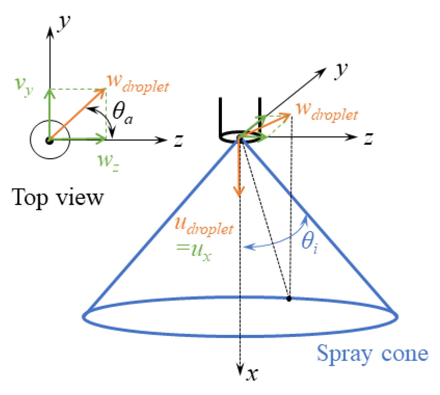
In CFD, the computational domain is usually based on the Cartesian coordinate system. For the group with circumferential direction θ a , spray angle θ i , and droplet size d j , as shown in Figure 5, the velocity components in the Cartesian coordinate system are calculated as follows:
u x = U · cos ( θ i )
v y = U · sin ( θ i ) · cos ( θ a )
w z = U · sin ( θ i ) · sin ( θ a )
where u x , v y , and w z represent the velocity components of droplets in the x-, y-, and z-axis directions of the computational domain, respectively. The mass flow rate of this group of droplets is as follows:
m ˙ i j = m ˙ / N a · Y θ , i · Y d , j

2.5. Summary of the Comprehensive Atomization Model for Pressure Swirl Atomizers

Here, the construction process of the comprehensive atomization model is summarized. The model includes the internal flow sub-model, the liquid sheet instability sub-model, the primary atomization sub-model, and the droplet velocity sub-model. The relationships between these submodels are shown in Figure 6. The inputs for the internal flow sub-model, which are also the overall inputs for the comprehensive atomization model, include the atomizer exit diameter D o , nominal half-cone spray angle of the atomizer θ ¯ , and discharge coefficient C d . The former is the structural parameters of the atomizer, while the latter two need to be obtained through experiments or provided by the atomizer manufacturer. The internal flow sub-model predicts the air core diameter d a and liquid sheet velocity ( U ¯ l , W ¯ l ) at the exit, which serve as inputs for the liquid sheet linear instability analysis sub-model. This sub-model then provides the wavelength and corresponding growth rate of surface waves on the liquid sheet. The primary atomization sub-model uses the wavelengths and their growth rates of the surface waves within the full range of unstable wavenumbers to predict the droplet size distribution of primary atomization. Based on this, the droplet velocity sub-model then determines the velocity of the droplets. This allows for a comprehensive prediction of the droplet diameter, quantity, and velocity resulting from primary atomization.

3. Model Implementation

The comprehensive atomization model can be integrated into the Eulerian–Lagrangian method to simulate the spray field of pressure swirl atomizers. Here, the integration method is exemplified using common commercial CFD software, Fluent.
In the Eulerian–Lagrangian method, the continuous phase (gas phase) is described using the Eulerian approach and is solved through the Navier–Stokes equations. In contrast, the discrete phase (droplets) is described using the Lagrangian approach, where each droplet is treated as sufficiently small particles, and their motion in the continuous phase is described using the motion equations under the Lagrangian description. The discrete phase can exchange momentum, mass, and energy with the continuous phase. The comprehensive atomization model developed in this research provides the initial conditions of the droplets of the discrete phase for the Eulerian–Lagrangian simulation.
The comprehensive atomization model is implemented into Fluent numerical simulations via file input as the initial conditions for the droplet discrete phase. Each line in the input file represents a group of droplets with the same circumferential direction, spray angle, and particle size, which is referred to as an injection in Fluent. The format of each line in the input file is as follows:
[ ( x y z u v w d T m ˙ ) name ]
where the name is optional, and the other inputs are mandatory. ( x , y , z ) is the position of the injection point, i.e., the center point of the nozzle exit plane, ( u , v , w ) is the velocity vector of the droplet injection, and d, T, m ˙ are the diameter, temperature, and mass flow rate of the group of droplets, respectively.
When using the standard droplet parcel method, each injection generates a droplet parcel at every time step of the discrete phase. The number of droplets contained in the parcel is given by the following equation:
n p a r c e l = 6 m ˙ ρ π d 3
The above comprehensive atomization model divides the spray produced by the pressure swirl atomizer into ( N k × N θ × N a ) injections, with each injection having the same circumferential direction, spray angle, and droplet particle size.
In the Eulerian–Lagrangian simulation, the turbulent stress in the flow field is simulated using the standard k ϵ turbulence model. The dynamic drag model is employed to calculate the drag force experienced by droplets moving in the gas phase. This model takes into account the deformation of droplets due to their interaction with air, which influences the magnitude of the drag force. The Taylor Analogy Breakup (TAB) model is used to simulate the secondary breakup of droplets, while O’Rourke’s collision probability method is employed to simulate collisions between droplets and further coalescence.
To simulate the spray of a pressure swirl atomizer in a stationary air environment, a simple cylindrical computational domain can be used. The boundary of the computational domain is set as a pressure outlet. After the spray field simulation is completed, the data table of discrete phase droplets is exported using the post-processing function of Fluent. This table records information such as the position, velocity, and diameter of all droplets, as well as the data of the droplets contained in each droplet parcel. Statistical analysis of the droplet diameter within a specific axial position range is then performed. The formula for calculating the Sauter Mean Diameter ( S M D ) is as follows:
S M D = i = 1 N p a r c e l n i , p a r c e l D i 3 i = 1 N p a r c e l n i , p a r c e l D i 2
Here, N p a r c e l is the number of droplet parcels in the spray field data, n i , p a r c e l is the number of droplets contained in the i-th droplet parcel, and D i is the diameter of the droplets contained in the i-th droplet parcel.

4. Experimental Testing Methods

4.1. Pressure Swirl Atomizer

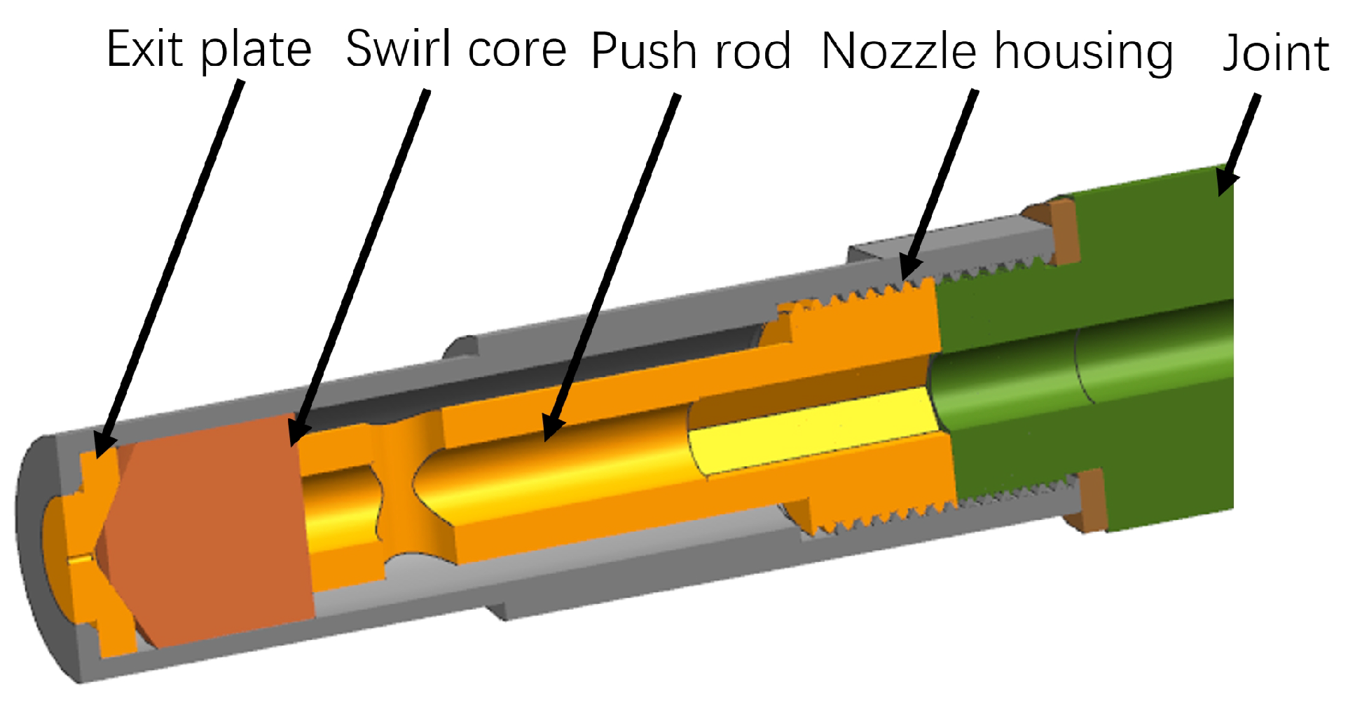
The structure of the pressure swirl atomizer used in this study is shown in Figure 7. The flow number of it is 1.15 kg / h / ( MPa ) 0.5 , and the diameter of the atomizer outlet is 0.16 mm. This PSA can produce a hollow cone spray with a spray angle of 80 degrees. As shown in Figure 7, the swirl core and the exit plate are pressed together inside the nozzle housing by a push rod, which is threaded into the nozzle housing. The nozzle housing is threaded onto the nozzle joint, with a sealing gasket between them for sealing. Fuel flows through the nozzle joint into the push rod, then through side openings in the push rod into the upstream of the swirl core. There is a gap between the swirl core and the nozzle housing for the fuel to flow through. The swirl slots on the conical surface of the swirl core cause the fuel to form a swirling flow in the chamber between the exit plate and the swirl core, and then the fuel flows through the atomizer exit, forming a hollow cone spray. The pressure swirl atomizer is designed with a minimum injection pressure of 0.1 MPa. When the injection pressure is greater than 0.1 MPa, the atomizer can operate normally.
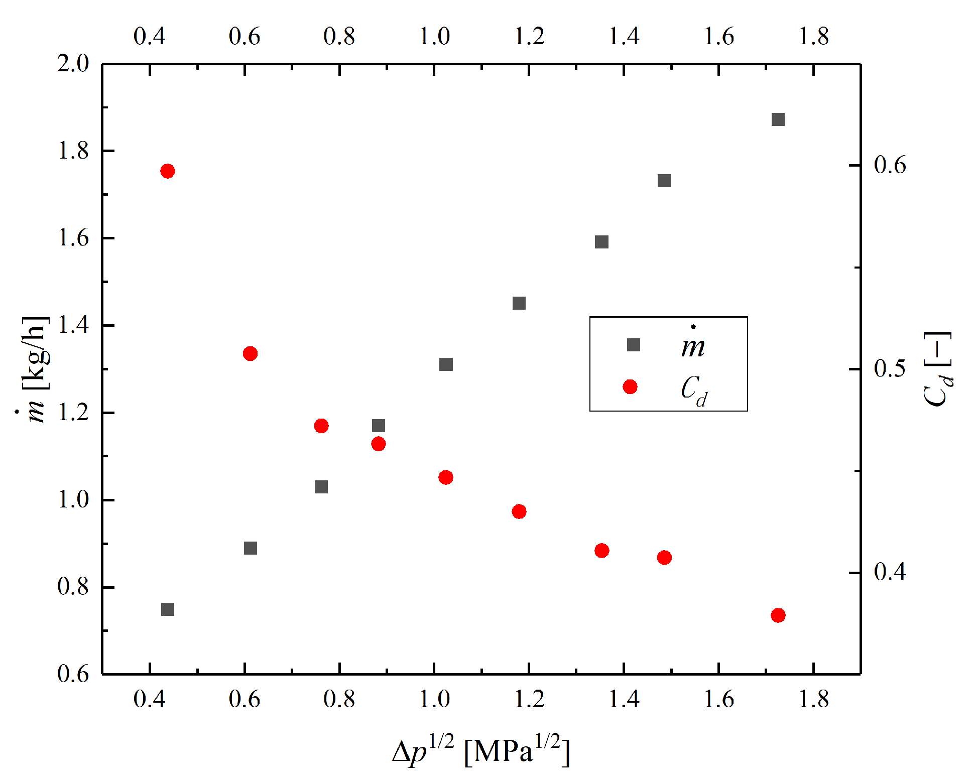
The flow characteristics of this pressure swirl atomizer are shown in Figure 8, which presents the mass flow rate under the square root of different pressure drops Δ P , as well as the discharge coefficient C d = Q ˙ / [ A o ( 2 Δ P ) / ρ l ] . The mass flow rate m ˙ has a linear relationship with Δ P 1 / 2 . The C d obtained here is one of the input parameters for the comprehensive atomization model. As the pressure drop increases, the discharge coefficient of the atomizer gradually decreases. This is because, with the increase in pressure drop, the liquid sheet thickness at the atomizer exit decreases, the effective flow area reduces, and the flow velocity increases, leading to higher flow losses. Besides, the working fluid used in the experiment is kerosene RP-3 with a density of 0.781 g/mL, a surface tension coefficient of 24.7 mN/m, and a kinematic viscosity of 1.73 × 10 6 m 2 / s .

4.2. Laser Diagnostics

The Sauter mean diameter of the spray field was measured using the laser diffraction method, and the spatial distribution of the spray field was obtained using Planar Mie (PMIE) Scattering measurements.
In this study, the Winner 319A laser particle analyzer, developed by Jinan Weina Co., Ltd., Jinan, China was used for laser diffraction droplet size measurements. The measurement range of this instrument is 1–500 micrometers. The instrumentation setup for the laser diffraction droplet size measurement is shown in Figure 9. The emitter and receiver of the laser particle analyzer are positioned on opposite sides of the spray field. The laser beam emitted by the emitter passes through the spray field, and the diffracted light is received by the receiver, with the diameter of the laser beam being approximately 10 mm. The distance between the atomizer outlet plane and the center of the laser beam is recorded as the axial position for the laser diffraction size measurement. Here, measurements are conducted at the axial position x = 40 mm. It is assumed that the particle size distribution of the spray follows a Rosin–Rammler distribution, and based on this assumption, the S M D of the spray is determined. Note, that before conducting laser diffraction size measurements on the spray, we tested the accuracy and repeatability of the instrument’s volume median diameter measurement using standard materials. The results showed that the accuracy and repeatability of the spray particle analyzer’s volume median diameter measurement were 1.91% and 2.08%, respectively, both of which are less than 3.0%, meeting the requirements for accuracy and repeatability.
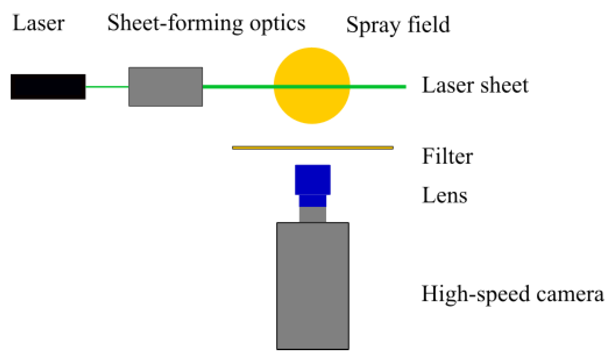
This work obtained the two-dimensional spatial distribution of the spray field by capturing the Mie scattering signal from droplets within the spray field illuminated by a planar laser sheet using a camera. The equipment used for PMIE Scattering measurements includes a laser, sheet-forming optics, a filter, a lens, and a high-speed camera, as shown in Figure 10. The laser is a continuous laser with a wavelength of 532 nm, model LASERWAVE LWGL532-10W-L, with a maximum power of 10 W. The sheet-forming optics expand the laser beam from the laser into a planar sheet approximately 1 mm thick, which is directed into the central section of the spray field. The filter used is a bandpass filter with a 10 nm full width centered at 532 nm. The high-speed camera model is Photron FASTCAM SA4. The camera operates at a frame rate of 5000 fps, with an exposure time of 1/12,000 s, and a resolution of 1024 × 800 pixels.

5. Results and Discussion

The comprehensive atomization model for pressure swirl atomizers is developed in this study based on the wavelength and growth rate of surface waves within the entire unstable wavenumber range. Therefore, we first discuss the linear instability of the swirling annular liquid sheet, and then analyze the effects of model parameters on the simulation results by comparing simulation results with experimental data to verify the accuracy of the comprehensive atomization model in terms of droplet size and spatial distribution of the spray.

5.1. Linear Instability of the Annular Liquid Sheet

According to the dimension and experimental conditions of the PSA tested in this paper, the parameter ranges for the linear instability analysis of the swirling annular liquid sheet can be obtained through the internal flow sub-model, as listed in Table 1.
Here, based on the input parameters given in Table 1, the dispersion relations obtained from the linear instability analysis under different operating conditions are shown in Figure 11. It presents the dispersion relations for the axisymmetric mode ( n = 0 ). The dispersion relation for the non-axisymmetric mode ( n > 0 ) is similar. The modeling of the primary atomization of the liquid sheet is also based on the dispersion relation under the axisymmetric mode. From the figure, it can be observed that as the flow rate increases, the range of unstable wavenumbers expands, and the maximum wave growth rate also increases. Note, that the results of the linear instability analysis indicate that, under the conditions in Table 1, only the disturbance waves of para-sinuous mode exist, while the para-varicose mode is absent. In the para-sinuous mode, the phase difference between the perturbation waves on the inner and outer surfaces of the annular liquid sheet is close to zero. Besides, the effects of important parameters (such as Re l , We l , and We s l ) on the instability of a swirling annular liquid sheet are not discussed here; relevant conclusions can be found in references [34,38,39].

5.2. Effect of Model Parameters on the Prediction of S M D

The model parameters involved in the present comprehensive atomization model include ligament constant C L , dispersion angle σ θ , number of azimuthal groups N a , number of spray angle groups N θ , and number of droplet size groups N k . This subsection studies the effect of model parameters on the accuracy of predicting the S M D of a PSA.
The S M D given by the numerical simulation depends mainly on the value of the ligament constant C L : the S M D of the droplets is proportional to the value of C L . Therefore, it is necessary to first determine an appropriate value for the ligament constant C L . When studying the effect of C L values on the prediction accuracy of S M D , the values of the other parameters are as follows: σ θ = 2 , N a = 36 , N θ = 30 , and N k = 20 .
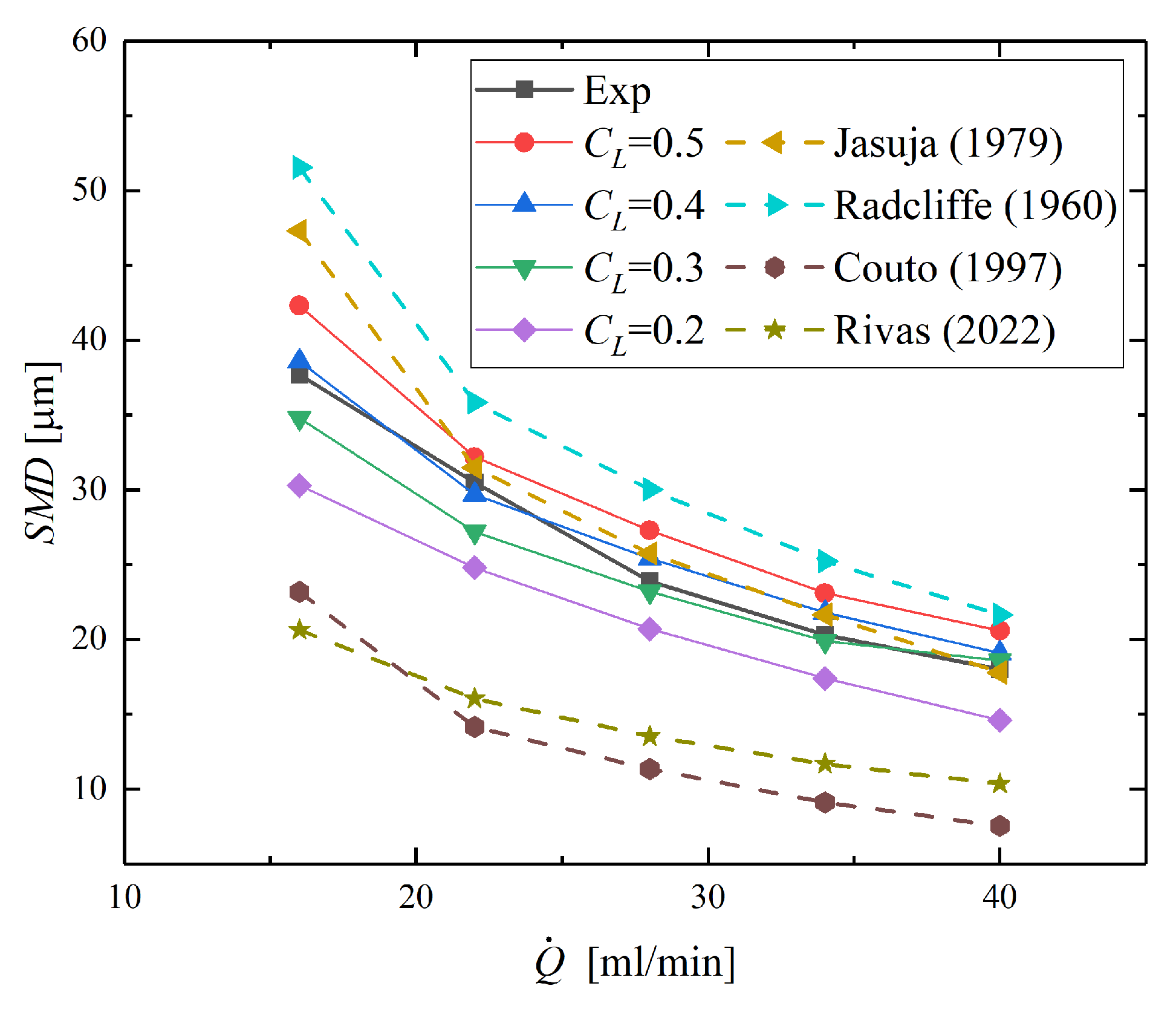
Figure 12 shows the comparison between the predicted and experimental values of the SMD for different values of C L . The tested values of C L include 0.2, 0.3, 0.4, and 0.5. From the comparison in the figure, it can be seen that both the experimental and predicted values of SMD decrease with the increase in flow rate. However, the rate of decrease in the experimental SMD with increasing flow rate is slightly greater than that of the predicted values. This difference may be due to the use of an inviscid theoretical model to predict the internal flow. Figure 12 also shows the comparison of SMD predictions obtained using the comprehensive atomization model and those calculated from commonly used correlations [7,17,23,40]. From the figure, it can be observed that the SMD predictions provided by the Radcliffe [40] correlation are overestimated, while the SMD predictions given by the Couto [17] and Rivas [23] correlations are underestimated. The Jasuja [7] correlation overestimates the SMD predictions at low flow rates but approaches the experimental values at high flow rates. The comparison indicates that the predictive performance of all the correlations is inferior to the comprehensive atomization model proposed in this paper.
Comparing Figure 12 with Figure 10 in Ref. [35], it can be found that the comprehensive atomization model proposed in this study performs better than the model by Liao et al. [35]. When the flow rate is relatively low ( Q ˙ < 25 mL/min), the predictive performance is best when C L is set to 0.4. When the flow rate is relatively high ( Q ˙ > 25 mL/min), the predictive performance is best when C L is set to 0.3. Over the entire range of operating conditions, the maximum relative error in simulating the SMD is less than 7% when C L = 0.4 , and the maximum relative error is 10% when C L = 0.3 . Further tests determine that C L = 0.35 should be used, with tests showing that the maximum relative error in predicting the SMD is 6%. In the subsequent simulations, C L is set to 0.35.
Next, we will study the effect of other model parameters, including the dispersion angle σ θ , the number of azimuthal groups N a , the number of spray angle groups N θ , and the number of droplet size groups N k on the S M D predictions. The baseline values of the model parameters are as follows: C L = 0.35 , σ θ = 2 , N a = 36 , N θ = 30 , and N k = 20 . Based on the baseline values, the effect of changing specific model parameters on the SMD prediction results is investigated.
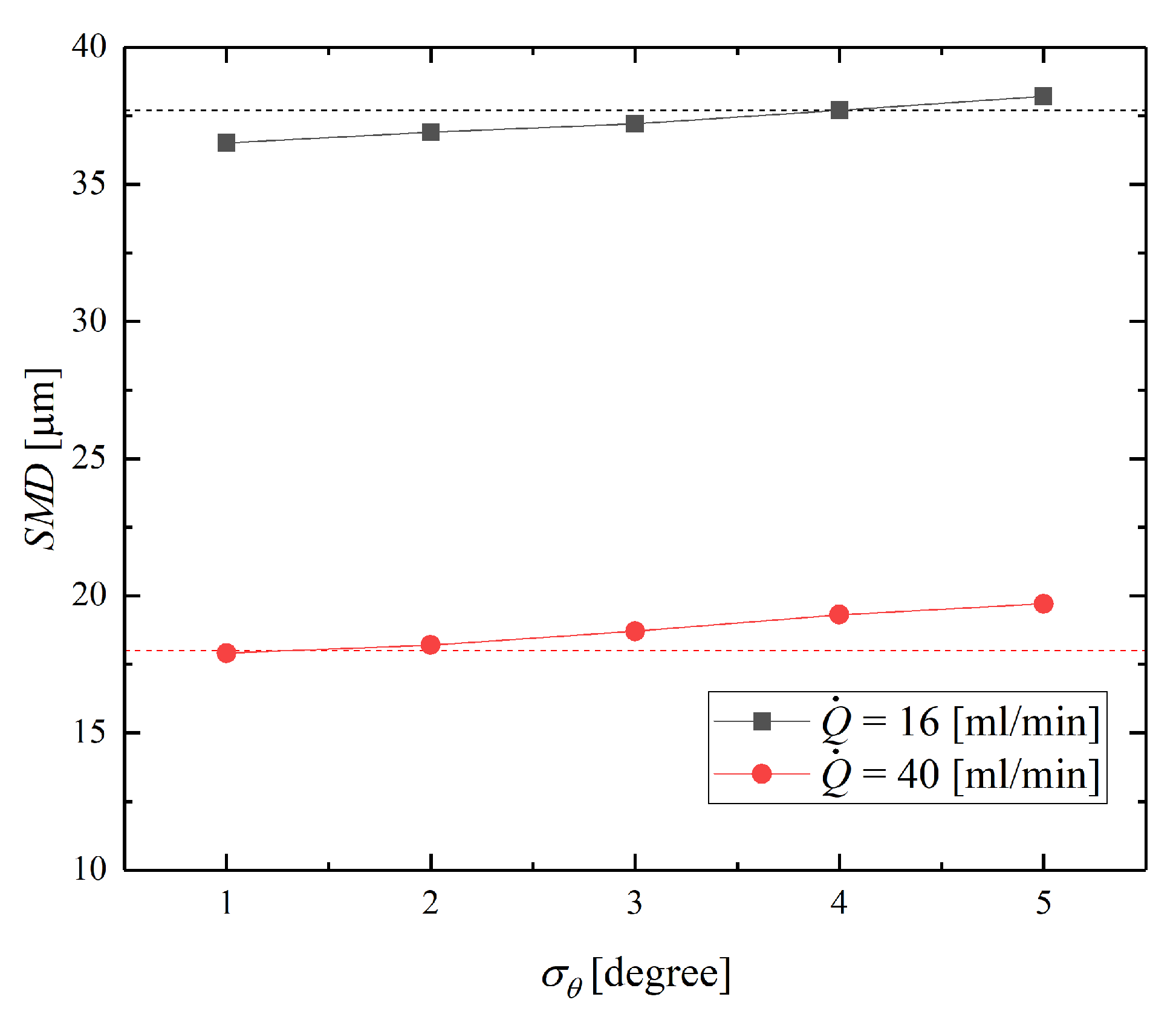
Figure 13 shows the effect of different values of the dispersion angle σ θ on the SMD prediction under two different operating conditions. It can be seen that increasing the spray dispersion angle σ θ will increase the predicted S M D . Since changing the value of σ θ only alters the velocity direction distribution of the droplets and does not affect the initial droplet size, the reason why increasing the spray dispersion angle causes the predicted S M D to increase should be because the increased spray dispersion angle changes the relative velocity between droplets, increasing the likelihood of collision and coalescence between droplets, thereby increasing the S M D of the spray field.
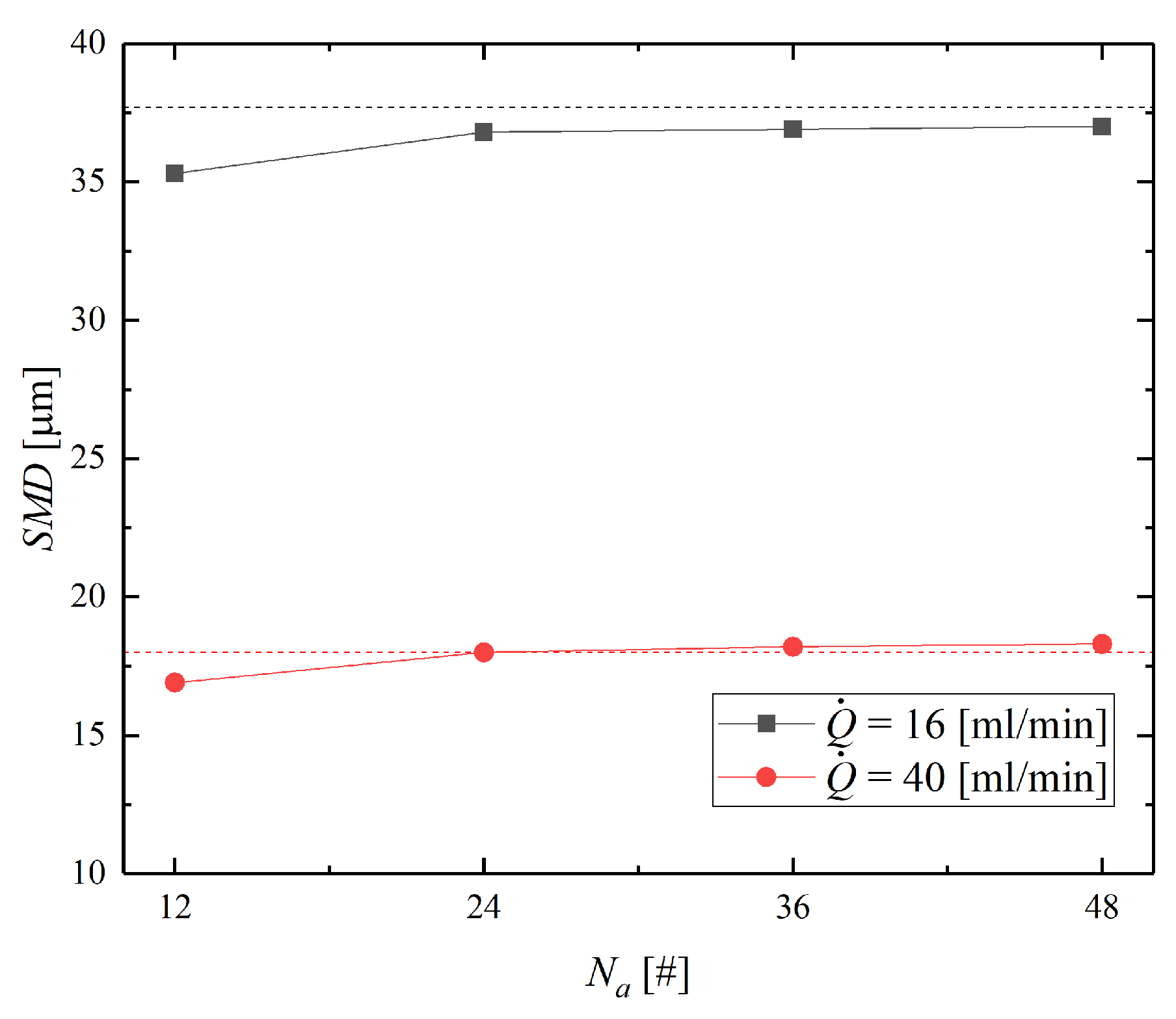
Figure 14 shows the effect of different values of N a on the SMD prediction results. N a represents the number of injections into which the spray is divided in the azimuthal direction. From the figure, it can be seen that increasing the number of azimuthal groups N a will increase the S M D of the spray field. This trend is more pronounced when the number of azimuthal groups ( N a 24 ) is small; when the number of azimuthal groups ( N a 36 ) is large, the degree of increase in S M D becomes very small. This is because dividing the spray into N a = 12 groups in the azimuthal direction prevents the spray from being evenly distributed in the azimuthal direction as in the realistic situation, confining the spray to 12 injection directions. Increasing the number of azimuthal groups makes the spray distribution more uniform in the azimuthal direction while increasing the likelihood of collision and coalescence between droplets, thus increasing the SMD. When the number of azimuthal groups N a is 36, the spray distribution in the azimuthal direction is considered to be already sufficiently uniform, and further increasing N a has little effect on the spray field, suggesting that the number of azimuthal groups of 36 is sufficient.
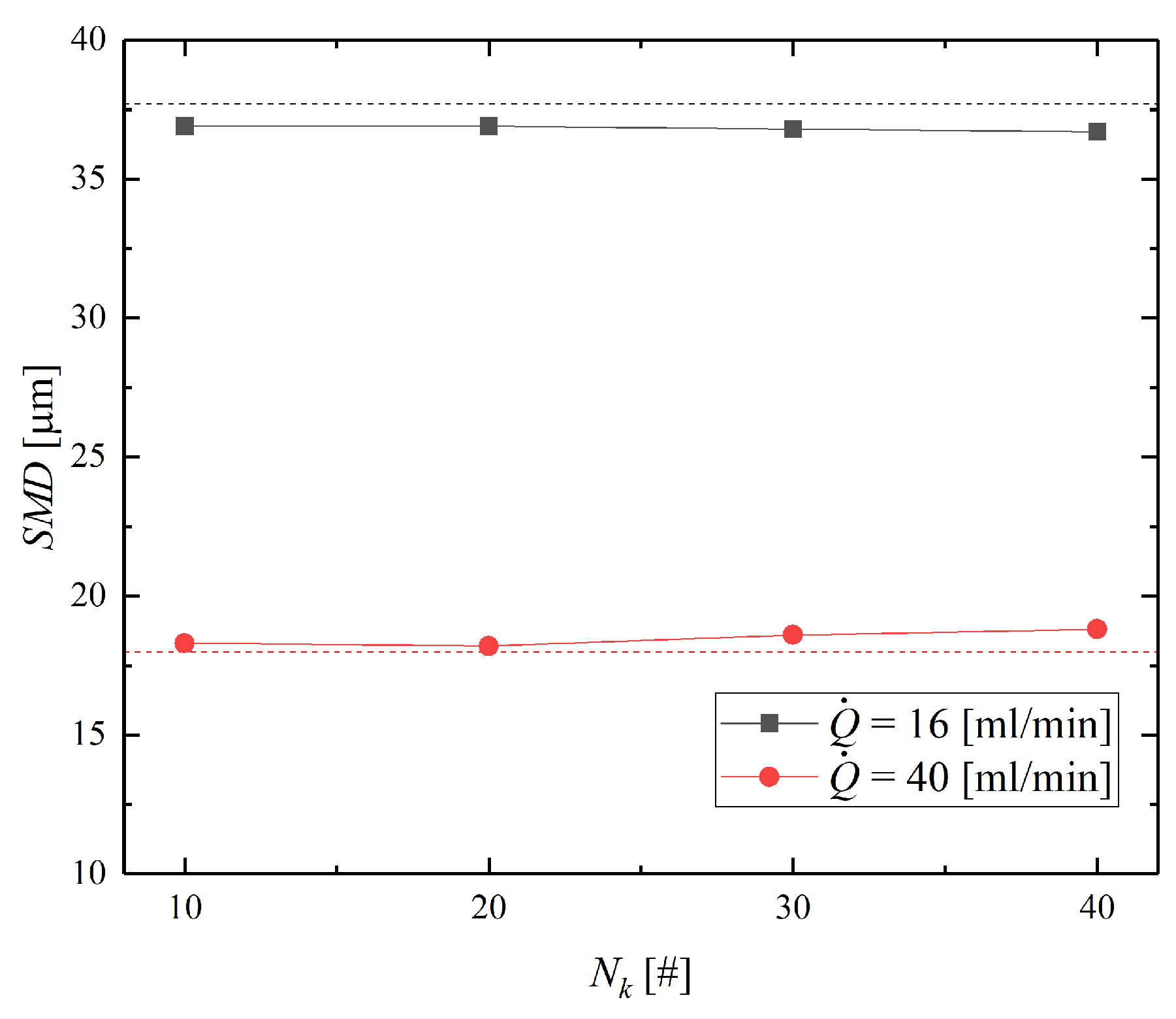
The effect of the number of spray angle groups N θ on the prediction results of S M D is shown in Figure 15. It can be seen that increasing N θ slightly increases the S M D under the small flow rate conditions, while it slightly decreases the S M D under the large flow rate conditions. Overall, changing the value of N θ has a minimal impact on the predicted SMD. Figure 16 illustrates the effect of varying the number of droplet size groups N k on the prediction results of S M D . The figure shows that increasing N k decreases the S M D value under the smaller flow rate conditions, while under the large flow rate conditions, increasing N k first decreases and then increases the S M D . Note, that N k is the number of sampling points within the unstable range of liquid sheet instability waves. Therefore, the differences in influence trends here are due to the differences in the instability dispersion relations of the liquid sheet under different conditions.
To quantify and compare the impact of model parameter changes on the predicted S M D , it is necessary to calculate the sensitivity of the S M D prediction values to these parameters. In this paper, the sensitivity S e of the S M D to a certain parameter P is defined as the relative change in the S M D prediction value caused by a relative change in the parameter value:
S e = 1 n i = 1 n | Δ S M D | / S M D B | Δ P | / P B × 100 %
where the subscript B represents the baseline value of the parameter, and n is the number of data points excluding the baseline value.
The sensitivities of the SMD prediction values to various parameters, calculated using Equation (58), are shown in Figure 17. From the figure, it can be seen that the most sensitive parameter is the number of azimuthal groups of the injection N a . Combined with the results in Figure 13, it is clear that when N a 24 , the SMD prediction value is highly sensitive to the value of N a . To ensure that the simulation results of the spray field are independent of the value of N a , N a needs to be set to N a 36 . However, further increasing the value of N a has little effect on the prediction results of the spray field and only increases the computational cost. Therefore, setting N a = 36 is appropriate.
Apart from N a , another parameter with relatively high sensitivity is the spray dispersion angle σ θ . Since the size of the spray dispersion angle directly determines the spatial distribution range of the droplets, simply studying the effect of σ θ on the SMD cannot fully reflect its impact on the prediction of the PSA spray field. Therefore, although the impact of σ θ on the SMD is limited, the effect of its value on the spray field structure and the spatial distribution of droplets will be studied in the next subsection. In comparison, it can be considered that the simulation results of the spray field are not sensitive to the values of N k and N θ within the given parameter range. The baseline values, N k = 20 and N θ = 30 , can be used in the comprehensive atomization model.

5.3. Effect of Model Parameters on the Simulation Results of the Spray Field

Based on the research from the previous subsection, the reasonable values for the model parameters are C L = 0.35 , σ θ = 2 , N a = 36 , N θ = 30 , and N k = 20 . It has been demonstrated that, by adopting these parameter settings, the characteristic droplet size in the spray field can be accurately predicted. However, it is unclear whether the comprehensive atomization model developed in this paper can accurately simulate the spray structure of the pressure swirl atomizer. Therefore, this subsection will study the value of the spray dispersion angle σ θ by comparing the PMIE imagings of the spray with numerical results, to verify the accuracy of the comprehensive atomization model in simulating the spray structure.
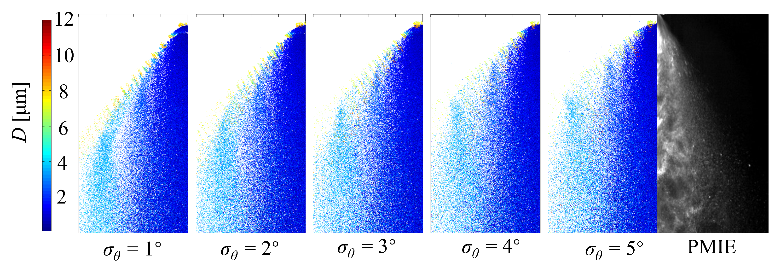
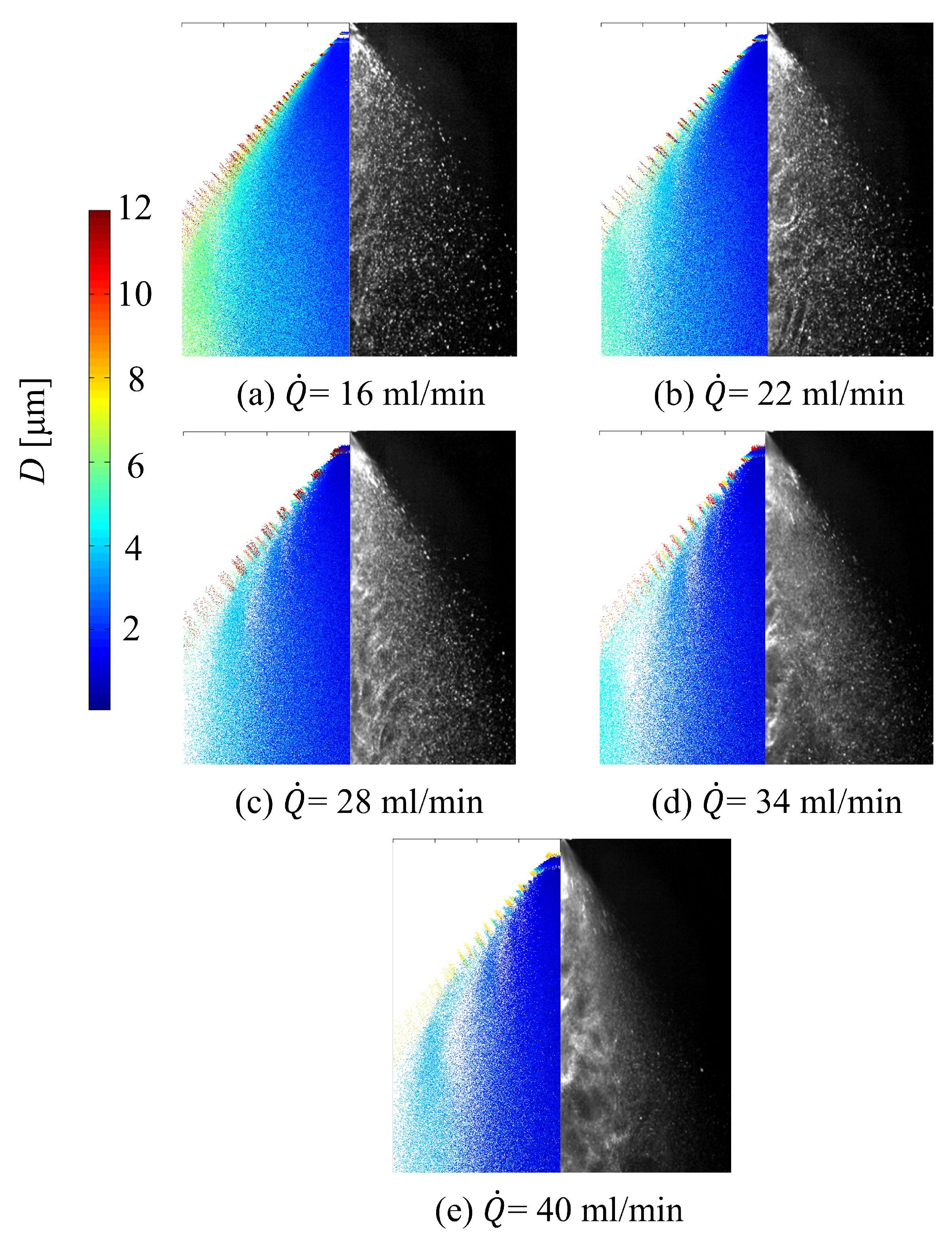
To compare the numerical results with PMIE results, the droplets within the y = 0 ± 5 mm plane in the simulation domain are visualized, with y = 0 being the central plane. Figure 18 and Figure 19 show the effect of the spray dispersion angle σ θ on the droplet distribution under two operating conditions: Q ˙ = 16 mL / min and Q ˙ = 40 mL / min , respectively. The numerical results and PMIE results of the droplet distribution are qualitatively compared in Figure 18 and Figure 19, with the radial range of the illustrated spray field being 0 z 40 mm. In the numerical results, the diameter of the scatters representing the droplets is proportional to the diameter of the droplets, and the scatter coloring also depends on the diameter of the droplets. From the comparison in Figure 18 and Figure 19, it can be seen that under both conditions, the spray field obtained by simulation has a structure similar to the actual spray field: larger diameter droplets are distributed at the outer edge of the spray cone with a lower number density, while smaller diameter droplets are found downstream in the center of the spray with a higher number density. As σ θ increases, the spray field obtained by simulation shows an increase in the overall spray cone angle. When σ θ = 1 , the spray cone angle of the simulation is closest to the experimental results. Additionally, it can be seen that at the axial position x = 40 mm, the droplet diameter increases with the increase in the value of the spray dispersion angle, which is consistent with the conclusions drawn previously. It should be noted that there is an obvious difference between the spray field obtained by simulation and the actual spray field near the atomizer exit: in the simulation, there is no droplet distribution immediately adjacent to the atomizer exit. This is because the initial velocity of the droplets is relatively high, and under the current simulation time step setting, the droplets move to a farther downstream position in the first time step, resulting in no droplet located near the atomizer exit. Reducing the simulation time step can reduce this difference, but it will significantly increase the number of tracked droplets in the simulation, thus greatly increasing the computational cost.
Setting σ θ = 1 , the spray field at different operating conditions was simulated. The qualitative comparison of the simulation results and the experimental results is shown in Figure 20. In Figure 20a, both the numerical results and the PMIE results show a dense region of small droplets at the axial position 5 < x < 20 mm of the atomizer axis, and further downstream along the axis, the droplet diameter increases; this increase in droplet diameter is due to the decrease in axial velocity of the droplets when moving in this direction, leading to collision and coalescence between droplets. Increasing the flow rate, as shown in Figure 20b–e, causes the dense region of small droplets in the center of the spray field to expand downstream and radially. Meanwhile, with the increase in flow rate, the spray cone angle slightly decreases, and the spray field obtained by simulation shows similar results. It should be noted that the nominal half-cone angle of the spray in the comprehensive atomization model remains 40 , so the simulated spray cone angle changes here are due to the changes in the spray characteristics in the simulation, qualitatively reflecting that the current comprehensive atomization model and numerical simulation method can capture main changes of the spray field under different conditions. Comparing Figure 20 with similar comparisons in the references [25,26], it can be found that the qualitative comparison results of droplet distribution shown in Figure 20 are better than those given by previous atomization models [25,26].
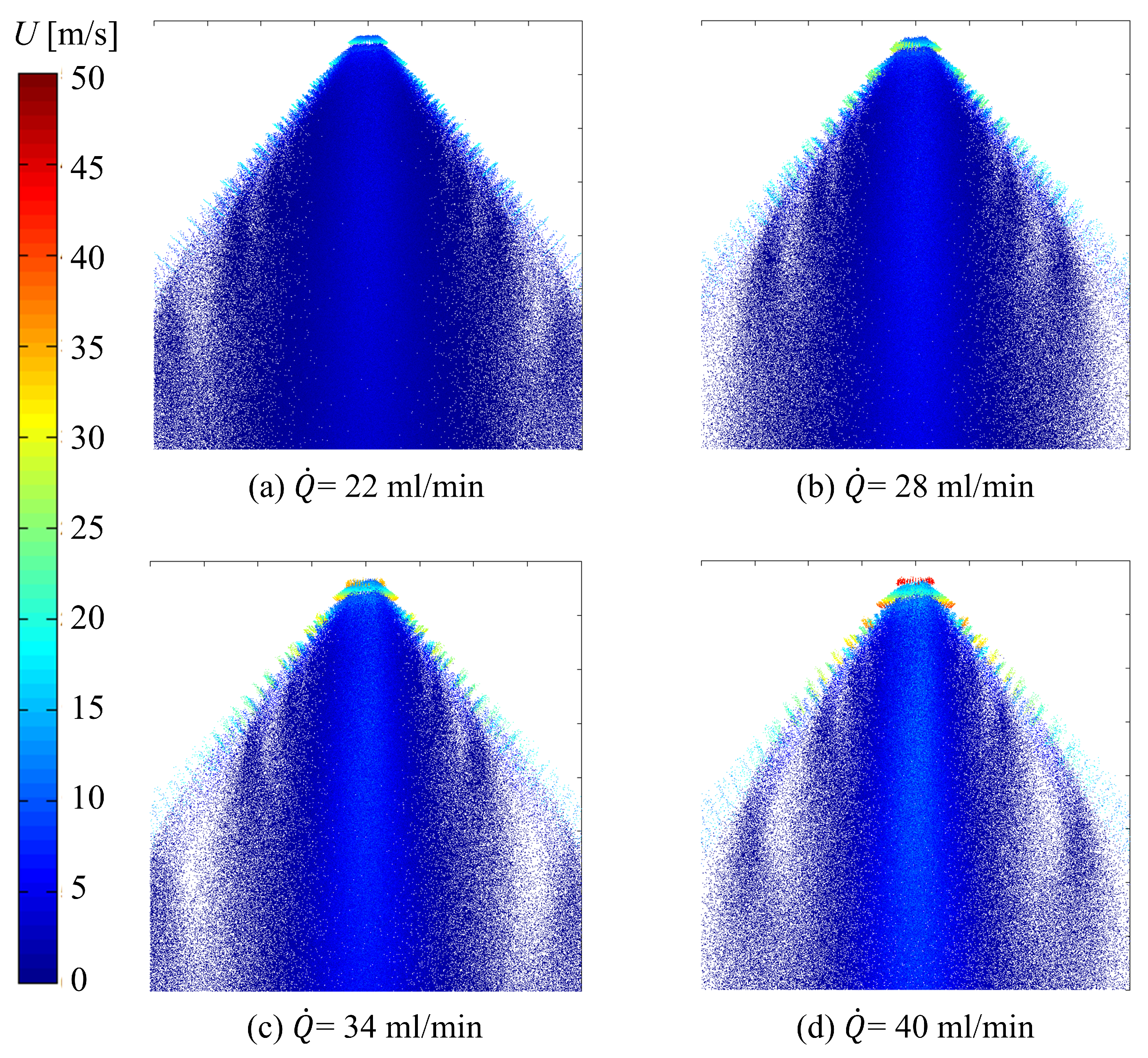
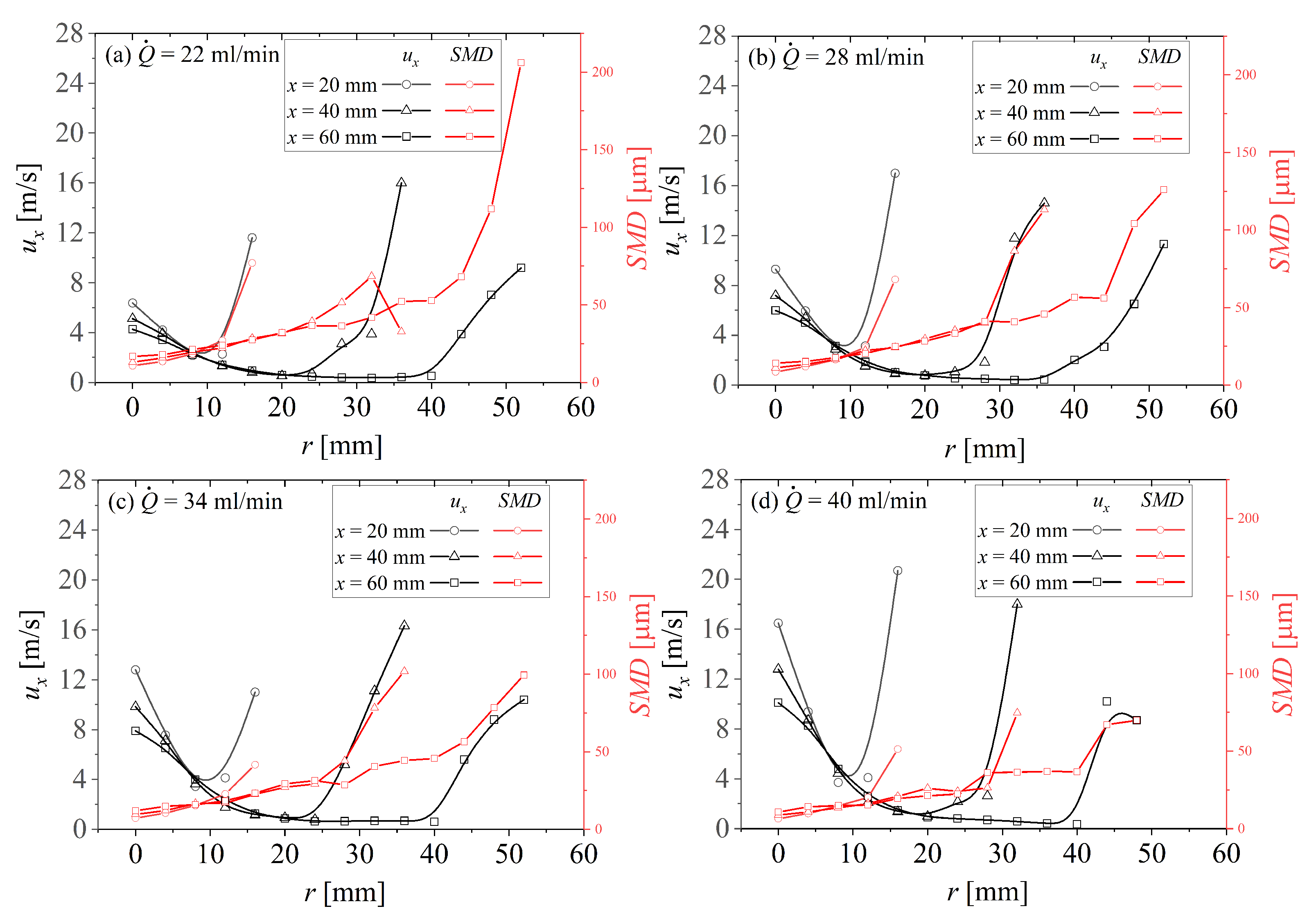
The spray structure shown in Figure 20 is formed by the momentum transfer between the gas phase and droplets. Since the injection is in a stationary atmosphere, momentum is transferred from the droplets to the air. The axial velocities of the droplets near the center section of the computational domain ( y = 0 ± 5 mm) under different operating conditions are shown in Figure 21. The scatter points are colored by the axial velocity of the droplets. Meanwhile, to better analyze the structure of the spray field, Figure 22 presents the radial distribution of the S M D and mean axial velocity at different axial positions ( x = 20 , 40 , and 60 mm) under different flow rates. It can be seen that in the spray cone angle direction, i.e., at the outer edge of the spray, large droplets maintain their initial velocity direction and have the highest axial velocity due to their larger inertia. In contrast, small droplets concentrated on the spray axis exhibit velocities lower than the spray edge but higher than other regions. The spray S M D is smallest along the atomizer axis and gradually increases as it moves away from the center radially. As the flow rate increases, the overall axial velocity of the droplets increases, and the S M D decreases.
The distribution of the gas phase axial velocity on the central section of the computational domain is shown in Figure 23. It can be seen that the distribution of the gas phase axial velocity is similar to that of a jet injecting into a stationary air field [41]: at a certain axial position, the maximum axial velocity is located on the atomizer axis, and the axial velocity gradually decreases radially. Downstream of the atomizer axis, this maximum value gradually decreases. As the flow rate increases, the maximum gas phase velocity on the atomizer axis also gradually increases. The axial velocity distribution of the gas phase shown in Figure 23 is consistent with the axial velocity distribution described by Hinterbichler et al. [41] which used a Phase-Doppler Particle Analyzer (PDPA) to measure the spray characteristics of pressure swirl atomizers. By using small droplets as tracer particles, they obtained the gas phase velocity and found that the axial velocity distribution of the gas phase of different atomizers exhibits a similar “bell” shape. This velocity distribution, formed by momentum transfer between the gas phase and the dispersed phase, is similar to the expansion of a gas jet and exhibits self-similarity. This consistency qualitatively reflects the accuracy of the current comprehensive atomization model. From Figure 21, it can be seen that the droplets near the atomizer outlet have high initial velocities when emanating from the atomizer, which through momentum transfer, cause the gas phase to form a high axial velocity on the spray axis. Small droplets have very little mass and inertia, allowing them to follow the flow effectively; hence a large number of small droplets concentrate on the spray axis and follow the gas jet.

6. Conclusions

In this study, an improved comprehensive atomization model for a pressure swirl atomizer is constructed by integrating predictions of internal flow within the atomizer, linear instability analysis of the swirling annular liquid sheet, the primary atomization sub-model of the liquid sheet, and the droplet velocity sub-model. Utilizing flow rate measurement data of the pressure swirl atomizer combined with the inviscid theory model, the internal flow of the atomizer is predicted, providing the velocity and thickness of the liquid sheet at the atomizer outlet. The dispersion relation of disturbances on the surface of the liquid sheet is obtained through linear instability analysis of the swirling annular liquid sheet. Then a primary breakup predictive model for the particle size distribution is constructed based on the wavelength and growth rate within the entire unstable wavenumber range of the dispersion relation. Finally, assuming uniform circumferential distribution of droplets and a normal distribution of spray angles, the droplet injection direction is given, and the velocity components of droplets are determined based on the liquid sheet velocity at the atomizer outlet and the droplet injection direction. The comprehensive atomization model is integrated into FLUENT as initial conditions for discrete phase droplets, and the spray field of the pressure swirl atomizer is simulated using the Eulerian–Lagrangian method.
To validate the comprehensive atomization model constructed in this study, experiments measured the spray characteristics of a specific pressure swirl atomizer at different pressure drops as validation data for the model. The laser diffraction technique was used to measure the S M D of the atomizer’s spray field, and planar Mie scattering was utilized to obtain the spatial distribution of the spray field. The measured S M D results of the spray field are compared with the predicted results of numerical simulations. This work analyzes the effects of model parameters, including ligament constant C L , dispersion angle σ θ , number of azimuthal groups N a , number of spray angle groups N θ , and number of droplet size groups N k , on the accuracy of predicting S M D . The results indicate that with an appropriately selected ligament constant C L = 0.35 , the comprehensive atomization model can accurately predict the S M D with a prediction error of less than 6%, and shows minimal dependence on other model parameters, demonstrating higher prediction accuracy than existing atomization models. This study qualitatively compares the spray structure simulated using the comprehensive atomization model with that obtained from planar Mie scattering measurements. The results show that, with a dispersion angle σ θ = 1 , the numerically simulated spray structure of the pressure swirl atomizer is very close to the experimental results, with similar spatial distribution patterns of droplets. The comprehensive atomization model can predict the variation of the spray cone angle with operating conditions and can also predict gas-phase velocity distribution patterns consistent with that given in the reference.

Author Contributions

Conceptualization, W.Q. and X.H.; methodology, W.Q., J.W. and R.C.; software, P.W. and R.C.; validation, S.Y. and J.W.; investigation, W.Q. and P.W.; resources, X.H.; data curation, W.Q., J.W. and S.Y.; writing—original draft preparation, W.Q.; writing—review and editing, X.H. and P.W.; visualization, W.Q. and R.C.; supervision, X.H.; project administration, X.H.; funding acquisition, W.Q. and X.H. All authors have read and agreed to the published version of the manuscript.

Funding

This research was funded by National Natural Science Foundation of China (Grant No. 12302332) and Natural Science Foundation of Jiangsu Province (Grant No. BK20230532).

Data Availability Statement

Data will be made available on request.

Conflicts of Interest

The authors declare no conflicts of interest.

Nomenclature

Aaera
C d discharge coefficient
C L ligament constant
D o atomizer outlet diameter
d a air core diameter
Finterface function
gdensity ratio
hratio of the inner to outer radius of the annular liquid sheet
kaxial wave number
m ˙ mass flow rate
Nnumber of groups
nazimuthal wave number
n unit normal interface vector
ppressure
Q ˙ volume flow rate
R a inner radius of the liquid sheet
R b outer radius of the liquid sheet
Re Reynolds number
t f liquid sheet thickness
Utotal velocity magnitude of droplet
U ¯ mean axial velocity
V instantaneous velocity vector
W ¯ mean tangential velocity
We Weber number
Ymass flow rate ratio
Greek Symbols
Ω l swirl strength of the liquid sheet
ω complex wave frequency
ϕ phase difference between the disturbances on two interfaces
ψ liquid sheet area coefficient
ρ density
σ surface tension coefficient
σ θ spray dispersion angle
θ spray half angle
η radial displacement of the interface
ν dynamic viscosity
λ wavelength
subscripts
aair
lliquid
ooutlet
sswirl
Abbreviations
CFDcomputational fluid dynamics
ODEordinary differential equations
PSApressure swirl atomizer
SMDsauter mean diameter

References

  1. Yu, S.H.; Si, H.Q.; Chen, C.; Wang, S.J.; Japhet, J.J. Experimental investigation on the impact of air flow rates and back pressures on kerosene microscopic spray characteristics discharged from an air-assisted pressure-swirl atomizer. Int. Commun. Heat Mass Transf. 2024, 151, 107247. [Google Scholar] [CrossRef]
  2. Leng, X.Y.; Yang, S.; Deng, Y.C.; Jin, Y.; He, Z.X.; Yan, X.S.; Feng, Z.H.; Li, C.; Wang, Q.; Long, W.Q. An experimental study on the in-nozzle cavitating flow and near-field breakup of spirally grooved hole nozzles. Int. Commun. Heat Mass Transf. 2022, 139, 106406. [Google Scholar] [CrossRef]
  3. Duan, R.Z.; Du, J.B.; Fu, Q.F.; Yue, Y.H.; Liu, T.; Liu, L.S. Investigation on pressure-swirl atomization for cooling and efficiency improvement of photovoltaic module. Appl. Therm. Eng. 2024, 244, 122720. [Google Scholar] [CrossRef]
  4. Zhang, X.G.; Qiao, W.T.; Gao, Q.X.; Zhang, D.W.; Yang, L.J.; Fu, Q.F. Experimental study on the dynamic characteristics of gas-centered swirl coaxial injector under varying ambient pressure. Aerospace 2023, 10, 257. [Google Scholar] [CrossRef]
  5. He, C.M.; Luo, W.H.; Zhang, P.; He, Z.X.; Yue, L.J. Spray combustion characteristics of a gas-liquid pintle injector with variable swirl intensities. Phys. Fluids 2023, 35, 097111. [Google Scholar] [CrossRef]
  6. Tharakan, T.J.; Mukhopadhyay, A.; Datta, A.; Milind, A.J. Trends in comprehensive modeling of spray formation. Int. J. Spray Combust. Dyn. 2013, 5, 123–180. [Google Scholar] [CrossRef]
  7. Jasuja, A.K. Atomization of crude and residual fuel oils. J. Eng. Gas Turbines Power 1979, 101, 250–258. [Google Scholar] [CrossRef]
  8. Kennedy, J.B. High weber number SMD correlations for pressure atomizers. J. Eng. Gas Turbines Power 1986, 108, 191–195. [Google Scholar] [CrossRef]
  9. Ballester, J.; Dopazo, C. Drop size measurements in heavy oil sprays from pressure swirl nozzles. At. Sprays 1996, 6, 377–408. [Google Scholar]
  10. Kang, Z.T.; Wang, Z.G.; Li, Q.L.; Cheng, P. Review on pressure swirl injector in liquid rocket engine. Acta Astronaut. 2018, 145, 174–198. [Google Scholar] [CrossRef]
  11. Lefebvre, A.H.; McDonell, V.G. Atomization and Sprays, 2nd ed.; CRC Press: Boca Raton, FL, USA, 2017; pp. 135–145. [Google Scholar]
  12. Wang, X.F.; Lefebvre, A.H. Mean drop sizes from pressure swirl nozzles. J. Propuls. Power 1987, 3, 11–18. [Google Scholar] [CrossRef]
  13. Lefebvre, A.H. Hydrodynamics, 1st ed.; Hemisphere: Washington, DC, USA, 1983. [Google Scholar]
  14. Dombrowski, N.; Johns, W.R. The aerodynamic instability and disintegration of viscous liquid sheets. Chem. Eng. Sci. 1963, 18, 203–214. [Google Scholar] [CrossRef]
  15. Xiao, W.; Huang, Y. Improved semiempirical correlation to predict sauter mean diameter for pressure swirl atomizers. J. Propuls. Power 2014, 30, 1628–1635. [Google Scholar]
  16. Chu, C.C.; Chou, S.F.; Lin, H.I.; Liann, Y.H. Theoretical analysis of heat and mass transfer in swirl atomizers. Heat Mass Transf. 2007, 43, 1213–1224. [Google Scholar] [CrossRef]
  17. Couto, H.S.; Carvalho, J.A., Jr.; Bastos-Netto, D. Theoretical formulation for sauter mean diameter of pressure swirl atomizers. J. Propuls. Power 1997, 13, 691–696. [Google Scholar] [CrossRef]
  18. Jafari, S.; Kebriaee, A.; Sohrabi, S. A comprehensive predictive model to anticipate droplets size distribution in pressure swirl atomizer. In Proceedings of the ILASS-Europe 2017, Valencia, Spain, 6–8 September 2017; p. 4845. [Google Scholar]
  19. Som, S.K.; Mukherjee, S.G. Theoretical and experimental investigations on the formation of air core in a swirl spray atomizing nozzle. Appl. Sci. Res. 1980, 36, 173–196. [Google Scholar] [CrossRef]
  20. Amini, G. Liquid flow in a simplex swirl nozzle. Int. J. Multiph. Flow 2016, 79, 225235. [Google Scholar] [CrossRef]
  21. Tharakan, T.J.; Ramamurthi, K.; Balakrishnan, M. Nonlinear breakup of thin liquid sheets. Acta Mech. 2002, 156, 29–46. [Google Scholar] [CrossRef]
  22. Herrero, E.P.; Del Valle, E.M.M.; Galan, M.A. Instability study of a swirling annular liquid sheet of polymer produced by air-blast atomization. Chem. Eng. J. 2007, 133, 69–77. [Google Scholar] [CrossRef]
  23. Rivas, J.R.; Pimenta, A.P.; Lessa, J.S.; Rivas, G.R. An improved theoretical formulation for Sauter mean diameter of pressure-swirl atomizers using geometrical parameters of atomization. Propuls. Power Res. 2022, 2, 007. [Google Scholar]
  24. Yan, K.; Ning, Z.; Lü, M.; Sun, C. Study on Droplet Size and Velocity Distributions of a Pressure Swirl Atomizer Based on the Maximum Entropy Formalism. Entropy 2015, 17, 580–593. [Google Scholar] [CrossRef]
  25. Senecal, P.K.; Schmidt, D.P.; Nouar, I.; Rutland, C.J.; Reitz, R.D.; Corradini, M.L. Modeling high-speed viscous liquid sheet atomization. Int. J. Multiph. Flow 1999, 25, 1073–1097. [Google Scholar] [CrossRef]
  26. Moon, Y.; Kim, D.; Yoon, Y. Improved spray model for viscous annular sheets in a swirl injector. J. Propuls. Power 2010, 26, 267–279. [Google Scholar] [CrossRef]
  27. Maly, M.; Slama, J.; Cejpek, O.; Jedelsky, J. Searching for a Numerical Model for Prediction of Pressure-Swirl Atomizer Internal Flow. Appl. Sci. 2022, 12, 6357. [Google Scholar] [CrossRef]
  28. Qian, W.J.; Hui, X.; Zhang, C.; Xu, Q.H.; Lin, Y.Z.; Sung, C.J. A numerical study of the internal flow in a pressure swirl atomizer. In Proceedings of the ASME Turbo Expo 2017, Charlotte, NC, USA, 26–30 June 2017. GT2017-64149. [Google Scholar]
  29. Sakman, A.T.; Jog, M.A.; Jeng, S.M.; Benjamin, M.A. Parametric study of simplex fuel nozzle internal flow and performance. AIAA J. 2000, 38, 1214–1218. [Google Scholar] [CrossRef]
  30. Giffen, E.; Muraszew, A. The Atomisation of Liquid Fuels; Chapman & Hall: London, UK, 1953; pp. 67–115. [Google Scholar]
  31. Khavkin, Y.I. The Theory and Practice of Swirl Atomizers; CRC Press: New York, NY, USA, 2004. [Google Scholar]
  32. Bazarov, V.; Yang, V.; Puri, P. Design and Dynamics of Jet and Swirl Injectors; American Institute of Aeronautics and Astronautics: Reston, VA, USA, 2004; pp. 19–103. [Google Scholar]
  33. Ronceros, J.; Raymundo, C.; Ayala, E.; Rivera, D.; Vinces, L.; Ronceros, G.; Zapata, G. Study of internal flow in open-end and closed pressure-swirl atomizers with variation of geometrical parameters. Aerospace 2023, 10, 930. [Google Scholar] [CrossRef]
  34. Hui, X.; Qian, W.J.; Lin, Y.Z.; Zhang, C.; Wang, J.C. Effects of liquid and air swirls on the three-dimensional instability of an annular viscous liquid sheet. Fuel 2021, 292, 120227. [Google Scholar] [CrossRef]
  35. Liao, Y.; Sakman, A.T.; Jeng, S.M.; Jog, M.A.; Benjamin, M.A. A comprehensive model to predict simplex atomizer performance. J. Eng. Gas Turbines Power 1999, 121, 285–294. [Google Scholar] [CrossRef]
  36. Qian, W.J.; Lin, Y.Z.; Hui, X. Effect of heat and mass transfer on the instability of an annular liquid sheet. Int. J. Heat Mass Transf. 2019, 143, 118499. [Google Scholar] [CrossRef]
  37. Liu, L.H.; Fu, Q.F.; Yang, L.J. Theoretical atomization model of liquid sheet generated by coaxial swirl injectors. Int. J. Multiph. Flow 2021, 142, 103725. [Google Scholar] [CrossRef]
  38. Fu, Q.F.; Yang, L.J.; Wang, X.D. Theoretical and experimental study of the dynamics of a liquid swirl injector. J. Propuls. Power 2010, 26, 94–101. [Google Scholar] [CrossRef]
  39. Fu, Q.F.; Yang, L.J. Theoretical investigation of the dynamics of a gas-liquid coaxial swirl injector. J. Propuls. Power 2011, 27, 144–150. [Google Scholar]
  40. Radcliffe, A. Fuel injection. In High Speed Aerodynamics and Jet Propulsion; Princeton University Press: Princeton, WV, USA, 1960. [Google Scholar]
  41. Hinterbichler, H.; Steiner, H.; Brenn, G. Self-similar pressure-atomized sprays. J. Fluid Mech. 2020, 889, A17. [Google Scholar] [CrossRef]
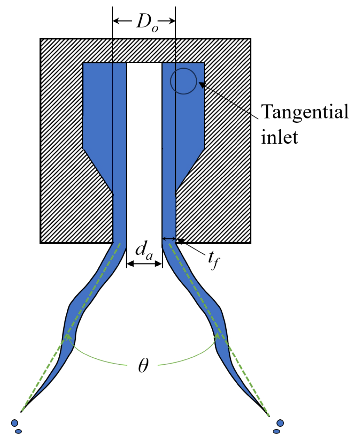
Figure 1. Schematic of a pressure swirl atomizer.
Aerospace 11 00658 g001
Figure 2. Schematic of the swirling annular liquid sheet.
Aerospace 11 00658 g002
Figure 3. Schematic of the velocity decomposition in the cylindrical coordinate system.
Aerospace 11 00658 g003
Figure 4. Schematic of the spray dispersion angle σ θ .
Aerospace 11 00658 g004
Figure 5. Schematic of the velocity decomposition in the Cartesian coordinate system.
Aerospace 11 00658 g005
Figure 6. Structure of the comprehensive atomization model.
Aerospace 11 00658 g006
Figure 7. Structure of the pressure swirl atomizer.
Aerospace 11 00658 g007
Figure 8. Flow characteristics of the pressure swirl atomizer.
Aerospace 11 00658 g008
Figure 9. Instrumentation setup for laser diffraction droplet size measurement.
Aerospace 11 00658 g009
Figure 10. Instrumentation setup for PMIE measurement.
Aerospace 11 00658 g010
Figure 11. Dispersion relations under different operating conditions. Horizontal axis: k represents the dimensionless axial wavenumber; vertical axis: ω i represents the dimensionless wave growth rate.
Aerospace 11 00658 g011
Figure 12. Experimental values (Exp) of S M D compared with numerical predictions at different C L and predictions by correlations of Jasuja [7], Radcliffe [40], Couto [17] and Rivas [23].
Aerospace 11 00658 g012
Figure 13. Effect of σ θ on the predicted S M D . Dashed lines represent the S M D measurements corresponding to the respective flow rates.
Aerospace 11 00658 g013
Figure 14. Effect of N a on the predicted S M D . Dashed lines represent the S M D measurements corresponding to the respective flow rates.
Aerospace 11 00658 g014
Figure 15. Effect of N θ on the predicted S M D . Dashed lines represent the S M D measurements corresponding to the respective flow rates.
Aerospace 11 00658 g015
Figure 16. Effect of N k on the predicted S M D . Dashed lines represent the S M D measurements corresponding to the respective flow rates.
Aerospace 11 00658 g016
Figure 17. Sensitivity of S M D prediction values to various model parameters.
Aerospace 11 00658 g017
Figure 18. Effect of σ θ on droplet distribution at Q ˙ = 16 mL / min .
Aerospace 11 00658 g018
Figure 19. Effect of σ θ on droplet distribution at Q ˙ = 40 mL / min .
Aerospace 11 00658 g019
Figure 20. Qualitative comparison of predicted and experimental results of spray field structure under different operating conditions.
Aerospace 11 00658 g020
Figure 21. Scatter plots of droplet axial velocity at the central section of the spray field under different operating conditions.
Aerospace 11 00658 g021
Figure 22. Radial distributions of droplet mean axial velocity and S M D under different operating conditions.
Aerospace 11 00658 g022
Figure 23. Axial velocity contour of gas phase at the central section of the spray field under different operating conditions.
Aerospace 11 00658 g023
Table 1. Input parameters for the linear instability analysis.
Δ P Q ˙ m ˙ C d d a t f U ¯ l W ¯ l h Re l We l We sl
[ MPa ] [ ml / min ] [ g / s ] [ ] [ mm ] [ mm ] [ m / s ] [ m / s ] [ ] [ ] [ ] [ ]
0.192160.2080.5970.07810.040917.414.60.434807766539
0.581220.2860.4720.09240.033827.322.90.513126718891330
1.05280.3640.4470.09520.032435.930.10.529166532652298
1.83340.4420.4110.09920.030445.738.40.551212052913724
2.98400.5200.3790.1030.028656.347.30.571261380415659
Disclaimer/Publisher’s Note: The statements, opinions and data contained in all publications are solely those of the individual author(s) and contributor(s) and not of MDPI and/or the editor(s). MDPI and/or the editor(s) disclaim responsibility for any injury to people or property resulting from any ideas, methods, instructions or products referred to in the content.