Abstract
This paper investigates the distributed formation control of a group of leader-following spacecraft with bounded actuation and limited communication ranges. In particular, connectivity-preserving and collision-avoidance controllers are proposed for the leader with constant or time-varying velocity, respectively. The communication graph between the spacecraft is modeled via a distance-induced proximity graph. By designing a virtual proxy for each spacecraft, the spacecraft–proxy couplings address the actuator saturation constraints. The inter-proxy dynamics incorporated with a bounded artificial potential function fulfill the coordination of all proxies. In addition, the bounded potential function can simultaneously tackle connectivity preservation and collision avoidance problems. The distributed formation controllers are proposed for multiple spacecraft with constant or time-varying velocities relative to the leader. A sliding mode control approach and the proxies’ dynamics are used in the design of a distributed cooperative controller for spacecraft to address the cooperative problem between the followers and the leader. Numerical simulations confirm the effectiveness of the anti-saturation distributed connectivity preservation controller.
1. Introduction
Formation control of multiple-spacecraft systems has gained significant attention due to its flexibility and robustness [1,2]. These advantages make it a competitive method to implement for space missions, including in synthetic-aperture radar, gravity field measurement, space-based interferometry, and distributed satellite architecture [3,4]. To improve the flexibility and robustness of spacecraft formations, the focus of formation control methods is gradually shifting from centralized to decentralized and distributed [5,6,7].
The distributed formation controllers enable each spacecraft to use the states of its neighbors to accomplish global tasks cooperatively. The artificial potential function method is a very common method for distributed formation control for spacecraft formation flying, and its earliest application can be traced back to [8,9]. Recently, Ref. [10] presented a collision-free formation controller for reconfiguration control of multiple spacecraft formations. In [11], a distributed cooperative controller was designed based on the artificial potential function and the sliding mode theory for spacecraft formation with obstacle avoidance. Kristiansen et al. have developed a distributed controller based on integral backstepping and passivity theory for a spacecraft formation attitude-track cooperative system [12]. In [13], the distributed cooperative control of spacecraft formation with communication time delay is achieved by using the consensus algorithm and backstepping method. A robust control method for the leader–follower formation with prescribed performance is proposed to address the issue of spacecraft formation flying in [14]. The development of distributed controllers requires the connectivity of the communication graphs at all times [6,15]. However, due to the communication range constraints of the spacecraft, the connectivity of the graph might be disrupted by the movements of the spacecraft. A more practical question is how to preserve the connectivity of the graph during formation flying [16].
Connectivity preservation controllers have been the focus of research in multi-agent systems and mobile robotic systems over the past decade [17]. Methods for preserving connectivity include optimization-based methods [18], artificial potential function-based methods [19,20,21], and edge-consensus-based methods [22]. Optimization-based methods fulfill connectivity preservation by maximizing the algebraic connectivity of the communication graph [23]. The potential function-based approach ensures connectivity of topological networks by using attractive potential functions at the boundaries [24,25]. The edge-consensus-based approach solves the problem by converting the formation problem into an edge-consensus problem [26]. However, most of the above connectivity-preserving control methods are for first- and second-order systems, which are not applicable to multiple spacecraft systems.
In recent years, there has been growing scholarly interest in the challenge of preserving connectivity control among multiple spacecraft. One study [27] provided a potential function-based control method to avoid collisions between spacecraft and preserve communication connectivity simultaneously. The connectivity preservation problem of leader–follower Lagrange systems is studied, and simulations with spacecraft relative dynamics are given in [28]. An additional study [29] examined the connectivity preservation coordinated control problem for multiple spacecraft systems subject to limited communication resources and sensing capability. However, the above studies did not consider the collision avoidance problem within formations. Ref. [30] tackled the connectivity preservation and collision avoidance issues in spacecraft formation flying, considering multiple obstacles and parametric uncertainties under a proximity graph. Similarly, a proposed adaptive tracking control scheme in another study [31] aimed to ensure inter-collision avoidance, obstacle dodging, and connectivity preservation in multi-spacecraft formations. Furthermore, Wei et al. delved into an adaptive leader-following formation tracking control approach for multiple spacecraft, considering directed communication topology, external disturbances, and limited sensing ranges [32]. A distributed controller proposed in Ref. [33] addressed spacecraft formation flying, focusing on preserving communication graph connectivity and preventing collisions despite bounded actuation.
In the current context, the challenge lies in developing distributed controllers for multiple leader-following spacecraft that address bounded actuation, connectivity preservation, and collision avoidance simultaneously. Building on previous discussions, this paper proposes a distributed controller with indirect couplings and bounded artificial potential functions. The approach begins by defining the communication graph among spacecraft based on their relative distances. It then introduces a bounded artificial potential function and outlines the design of a local second-order virtual proxy spacecraft for each individual spacecraft. These virtual proxies are integrated with the spacecraft using a saturated P + d controller [24]. The distributed formation controllers are proposed for multiple spacecraft with constant or time-varying velocities of the leader. A sliding mode control approach and the proxies’ dynamics are used in the design of a distributed cooperative controller for spacecraft to address the cooperative problem between the followers and the leader. Finally, the virtual proxies are linked through two potential functions. Numerical simulations confirm the effectiveness of the anti-saturation distributed connectivity preservation controller.
The paper is organized as follows: Section 2 states the relative dynamics of multiple spacecraft systems and introduces some concepts about algebra graph theory. Section 3 provides the distributed controllers for the leader with constant or time-varying velocity. Numerical simulations are presented in Section 4 to demonstrate the effectiveness of the proposed control methods. Finally, Section 5 concludes the paper with some final remarks.
2. Problem Statement
This paper mainly studies how to preserve the connectivity of the communication graph and avoid collisions between all spacecraft during formation reconfiguration. This section introduces the relative dynamics of spacecraft and some notions of algebraic graph theory.
2.1. Spacecraft Relative Dynamics
All spacecraft are assumed to be rigid, and the reference spacecraft belongs in an elliptical orbit. The reference frame, denoted by , has its origin at the centroid of the reference spacecraft. The axis is along the local vertical, the axis is perpendicular to the reference orbit plane, and the axis can be obtained according to the right-hand rule, as shown in Figure 1. Consider a system with rigid spacecraft denoted by with respect to the reference frame, where 0 denotes the leader and denote the N followers. The relative dynamics of spacecraft i with respect to the reference spacecraft are described by [34]
where
denotes the mass of the spacecraft i, denotes the control input to be designed, is the gravitational constant of the Earth, denotes the true anomaly of the reference spacecraft, denotes the distance of the origin of the reference frame to the Earth’s center, and represents the distance between the Earth’s center and the centroid of spacecraft i.
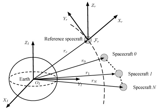
Figure 1.
The reference frame for the leader–follower formation.
2.2. The Dynamic Graph Model
The distance-induced proximity graph can be modeled by graph theory. Some notions of graph theory are presented in this subsection [35]. An undirected graph is denoted as , where denotes the vertex set and denotes the edges set. An edge if the vertex i can communicate with the vertex j, and they are called a neighbor of each other. denotes the neighbor set of vertex i, which is defined as . It is assumed that the neighbor relationship among the spacecraft is based on their relative distance. Suppose all spacecraft have the same sensing distance . The collision distance between spacecraft is denoted as . The adjacency matrix between all spacecraft is generated dynamically according to the current distances as follows:
where and , and are small constants, , and indicates spacecraft i can obtain the states of spacecraft j.
The Laplacian matrix is defined as
When the formation system contains the leader, its communication network is denoted as , where denotes the vertex set and denotes the edge set. The edge set contains the edges between the followers described in (2), but also the edges between the followers and the leader. In leader–follower spacecraft systems, since the leader is not affected by the following spacecraft. If the distance between spacecraft i and the leader is less than the communication distance and higher than the safety distance, then , otherwise . The above description can be written in matrix form:
Define the matrix , where . The notation denotes a diagonal matrix with diagonal entries . Since the Laplace matrix is symmetric and semi-positive definite, the matrix is also symmetric and semi-positive definite.
Lemma 1
([20]). The matrix is positive definite if there exists at least one directed path in the diagram from the leader to any follower.
To move on, we need the following definition.
Definition 1
([36]). Let and . If and have real entries, we write
Now, we introduce the following lemma.
Lemma 2
([28]). If is a sub-graph of , that is, , then we have .
Assumption 1.
The initial distance-induced proximity graph is connected, and there exists at least one spacecraft i such that .
Definition 1
([37]). The desired formation configuration is reachable if the following conditions hold
Assumption 2.
The desired formation is reachable.
2.3. Control Objective
This paper studies a distributed formation controller for multiple rigid spacecraft in the presence of bounded actuation, enabling all spacecraft to transition from their initial formation to the desired formation. The proposed method is designed to preserve the communication graph’s connectivity between all spacecraft during formation reconfiguration.
The saturation function is given first. The vector denotes the control input, whose upper bound is . The standard saturation function is defined as [38]
where
For the definition of the standard saturation function, one has the following lemma.
Lemma 3
([24]). Let denote the standard saturation function; for any two vectors the following conclusion holds:
For second-order systems, a counterexample is given in Ref. [39] to illustrate that bounded control inputs cannot guarantee the connectivity of the communication network between robots under certain initial conditions. Therefore, it is not feasible to design an anti-saturation controller for Equation (1) directly, and additional assumptions need to be made as follows.
Assumption 3.
At the initial moment, the follower is at rest relative to the reference coordinate frame, i.e., .
Assumption 4.
The velocity and acceleration of the leader is bounded, and the acceleration satisfies .
Assumption 5.
The saturation bound satisfies , where is the saturation bound for each spacecraft.
Remark 1.
From the results in [39,40] one knows Assumptions 1, 4, and 5 are reasonable. Assumption 2, which guarantees the desired formation is achievable, is also supported by [37]. Preserving the connectivity of a second-order system while using bounded control inputs, as described in Equation (1), is generally considered infeasible. An example demonstrating this challenge can be found in [39]. Therefore, Assumption 3 is reasonable.
With the above assumptions, the objective of this paper can be stated as the following problem.
Considering the dynamics (1), and ensuring that Assumptions 1–5 are met, design a controller to achieve the following objectives:
- If , then , , where is a small constant;
- , ;
- , for all as ;
- , for all as .
3. Controller Design
In this section, connectivity preservation and collision avoidance control for leader-following spacecraft systems with bounded actuation is studied. The design procedure is divided into two cases. First, a virtual proxy spacecraft dynamics is designed for each follower to solve the actuator input saturation problem. Second, a connectivity-preserving and collision avoidance controller is proposed for a leader with constant velocity. Finally, an improved controller is designed for a leader with time-varying velocity. The stability of these two control methods is theoretically ensured by utilizing the novel Lyapunov-like artificial potential functions.
3.1. Virtual Proxy Spacecraft Design
Define the following virtual proxy spacecraft for each follower:
where , , and and are positive constants. The upper bound for is given later. The bounded artificial potential function is proposed as
where and denote the repulsive and attractive artificial potential functions, respectively. They are defined as follows:
with , , and are positive constants, and P and Q are positive constants. It can be verified that and .
Remark 2.
Since the initial distances between the virtual spacecraft are equal to that of the real spacecraft, the initial distances between the real spacecraft should satisfy the potential function given in (7) and (8). Therefore, it is necessary to satisfy the following inequality:
Therefore, the parameters should satisfy and .
Lemma 4
([33]). The potential function ψ is monotonically increasing in regard to while , and monotonically decreasing while .
Lemma 5
([33]). Denote ; the virtual energy stored between spacecraft i and its virtual proxy can be written as
The energy function has the following properties:
- 1.
- is a convex function.
- 2.
- Within the domain , achieves its maximum while and its minimum while .
- 3.
- Letwhere . If , then .
Remark 3.
By the triangle inequality , it is enough to ensure while the following inequalities are satisfied:
Remark 4.
The energy function could be regarded as a virtual artificial potential function between the spacecraft i and its proxy. When the input of the controller reaches saturation, the energy function gradually increases. When the input of the controller is not saturated and the energy function is greater than zero, the energy function gradually decreases and eventually tends to zero.
3.2. Controller Design for a Leader with Constant Velocity
In this subsection, connectivity preservation and collision avoidance control for a leader with constant velocity is further investigated. First, define the following auxiliary parameters:
From the above equation, one has
Employing the dynamics of virtual proxy spacecraft, the controller is presented as follows:
where is a positive constant, and the saturation function is upper bounded by .
Define the following Lyapunov equation:
where
With Equation (15), the following lemma holds.
Lemma 6.
Consider the dynamics described in (1) and the Lyapunov function described in (15) under Assumption 3, where , and then, choosing appropriate parameters Q and P that satisfy
If , then , and .
The proof of Lemma 6 resembles Lemma 4 in [33], and is omitted here.
Theorem 1.
Consider the dynamics given by (1) under Assumptions 1–3 and 5, and with the parameters Q and P selected as in (18) and (19), the controllers (4) and (14) can attain the following objectives:
- (1)
- If , then , ;
- (2)
- , ;
- (3)
- , for all as ;
- (4)
- , for all as .
Proof.
Differentiating Equation (16) leads to
The constant velocity of the leader implies that . By substituting (1), (4), and (14) into (20), one has
The derivative of (17) yields
According to Assumption 1 and Lemmas 1 and 2, is positive definite. Therefore, one has , . It follows from Lemma 6 that . Therefore, the communication network between spacecraft is connected and no collisions occur, i.e., objectives (1) and (2) hold. The negative of (24) also guarantees , and . Therefore, as , that is, . By using (5), one has . As is continuously differentiable and bounded, one can obtain . The first-order derivative of (4) gives , and hence, . The second-order derivative of (4) shows . Thus, . Because , we have , i.e., all spacecraft can track the velocity of the leader. The derivative of (1) shows that . Therefore, and . Combining , and (4), one has , which further implies that . Overall, . □
3.3. Controller Design for a Leader with Time-Varying Velocity
In this subsection, connectivity preservation and collision avoidance control for a leader with time-varying velocity is further investigated. Firstly, we redefine the dynamics of the virtual proxy spacecraft:
where , , and and are positive constants.
By using the virtual dynamics, the controller is designed as follows:
where .
Theorem 2.
Consider the dynamics (1) with Assumptions 1–5, and the parameters Q and P are chosen according to (18) and (19). Using the controller (27) and (28) with parameters satisfying , then the following objectives can be achieved:
- (1)
- If , then , ;
- (2)
- , ;
- (3)
- , for all as ;
- (4)
- , for all as .
Proof.
Consider the same Lyapunov function as in Equation (15) and note that Equation (23) still holds. Substituting (25) and (27) into (20) yields
Using the inequality and noting that , (31) can be further reduced to
From and , (32) can be further simplified as
Remark 6.
In this paper, it is assumed that the acceleration information of the leader is unknown. This is because measuring or estimating the acceleration information of the leader often has a large error. We distinguish between the constant and varying velocity of the leader because the leader’s acceleration is not used when designing the connectivity preservation controllers. In the case of constant velocity, since the acceleration is zero, feedback control can be designed directly to realize distributed formation control of the spacecraft. When the velocity varies, since the acceleration is variable and unknown, the controller design needs to use the sign function to ensure that the follower can track the leader. In addition, the effect of the leader’s acceleration on the input saturation also needs to be taken into account.
Remark 7.
A special case of constant velocity is the case where the leader is the reference spacecraft. In this case, the leader’s velocity is zero. In addition, the proposed method is also applicable for the case where the leader is a virtual spacecraft with a reference trajectory and constant velocity. In the second case, the controller has a wider range of applications and can be used to realize distributed cooperative control for a leader with varying velocity. However, it is somewhat conservative compared to the controller in the first case. Furthermore, the second case requires a higher upper bound of the control force. Therefore, we design the controller for two cases.
4. Simulations
To confirm the effectiveness of the bounded actuation controller in (14) and (27), simulations with three spacecraft are presented in this section. The initial positions of the spacecraft are, respectively, m, m, m, and m. The communication range of all spacecraft is selected as m. From (2) and (3) we can obtain the communication network between the spacecraft, as shown in Figure 2. The desired distances between the spacecraft are, respectively, m, m, m, m, m. The parameters for the reference orbit are shown in Table 1.
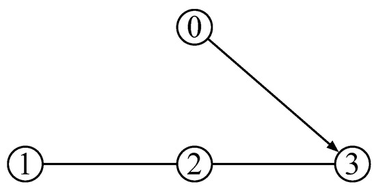
Figure 2.
Initial communications network , where 0 represents the leader and 1, 2, and 3 represent three followers.

Table 1.
Parameters for the reference orbit.
4.1. Leader with Constant Velocity
This subsection gives the simulation when the velocity of the leader is constant. The velocity of the leader in the simulation is . In addition, the maximum control input in each axis is assumed to be N, and the upper bound of the standard saturation function is N. The parameters are chosen as , , , , and .
The simulation results are presented in Figure 3, Figure 4, Figure 5, Figure 6, Figure 7, Figure 8 and Figure 9. Figure 3 displays the distances between all followers, while Figure 4 shows the distances between the followers and the leader. In both figures, the distances between the spacecraft are always greater than the safe distance, ensuring no collision occurs between spacecraft. Figure 3 also indicates that the distances between spacecraft 1 and 2, and between spacecraft 2 and 3, are always within the communication distance (). Additionally, Figure 4 demonstrates that the distance between spacecraft 3 and the leader is always less than the communication distance . In summary, the communication network is always connected, and spacecraft 3 is always able to obtain the status information of the leader, ensuring the connectivity of the communication network.
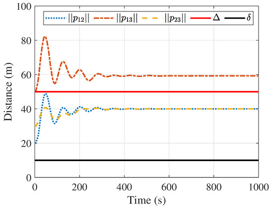
Figure 3.
Distances between the followers.
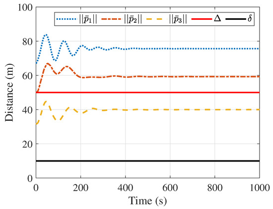
Figure 4.
Distances between the followers and the leader.
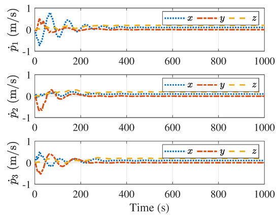
Figure 5.
Velocities of the followers.
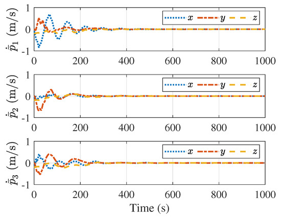
Figure 6.
Velocity errors between the followers and the leader.
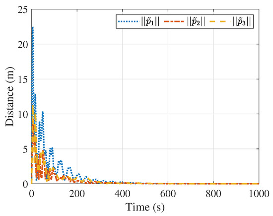
Figure 7.
Distances between the followers and their virtual proxy spacecraft.
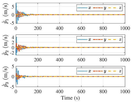
Figure 8.
Velocity errors between spacecraft and proxy spacecraft.
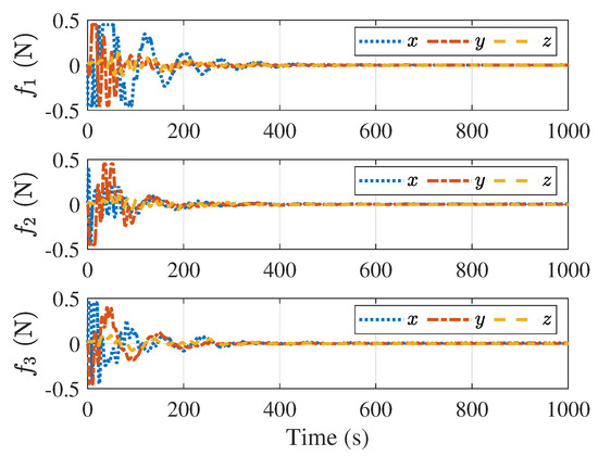
Figure 9.
Control forces of the followers.
Figure 5 and Figure 6 present the velocity of the followers and the velocity tracking error between the follower and the leader, respectively. Figure 5 suggests that all follower’s velocities eventually converge to a constant value, while Figure 6 indicates that the velocity tracking errors converge to zero, ensuring that all followers eventually converge to the velocity of the leader. Figure 7 and Figure 8 describe the distance and velocity errors between the followers and their virtual proxies, respectively. Figure 7 demonstrates that the distance between each follower and its virtual proxy eventually converges to zero, while Figure 8 demonstrates that the velocity error between each follower and its virtual proxy eventually converges to zero as well. Figure 9 displays the control input applied to the follower over time, which indicates that the maximum magnitude of the control force is less than N, satisfying the input saturation constraint.
4.2. Leader with Time-Varying Velocity
In this subsection, simulations are performed for the time-varying velocity of the leader. The spacecraft mass, initial position, velocity, and spacecraft communication distance are the same as in Section 4.1. The velocity of the leader in the simulation is . It is assumed that the maximum thrust that can be provided by each axis is 2 N.
Using the controllers (25)–(28), the upper bound of the standard saturation function is N. Choosing the parameters , , , , and , it is easy to verify that the constraints in Lemma 6 and Theorem 2 are satisfied.
Figure 10 and Figure 11 display the distances between the followers, and the distances between the followers and the leader, respectively. In both plots, the distance between all spacecraft is always greater than the safe distance, ensuring no collision occurs. Figure 10 indicates that the distances and are always within the communication distance. In addition, the distance in Figure 11 is always less than the communication distance between spacecraft. In summary, the inter-spacecraft communication network remains connected.
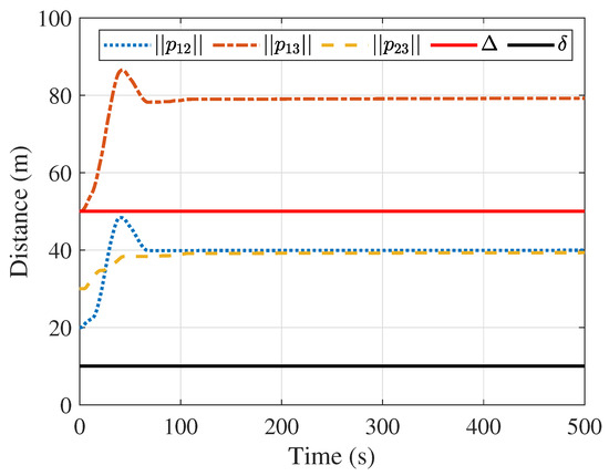
Figure 10.
Distances between the followers.
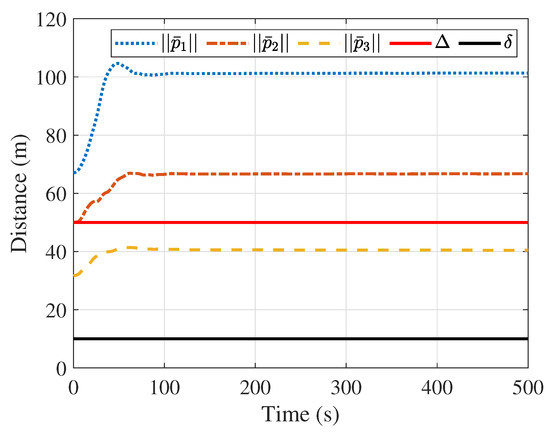
Figure 11.
Distances between the followers and the leader.
Figure 12 and Figure 13 show the velocities of the followers and the velocity tracking errors between the followers and the leader, respectively. Figure 12 demonstrates that despite the varying velocity of the leader, all velocity tracking errors converge to zero, and the followers achieve the velocity of the leader. Figure 14 and Figure 15 present the distances and velocity errors between the followers and their virtual proxy spacecraft, respectively. Figure 14 indicates that the distances between the followers and their virtual proxy spacecraft eventually converge to zero. Figure 15 shows that the velocity errors between the followers and the virtual spacecraft eventually also converge to zero. Figure 16 provides a plot of the control forces of the follower. Since the leader’s velocity is continuously changing, the control forces also vary, with their maximum magnitude remaining less than 2 N, satisfying the saturation constraint.
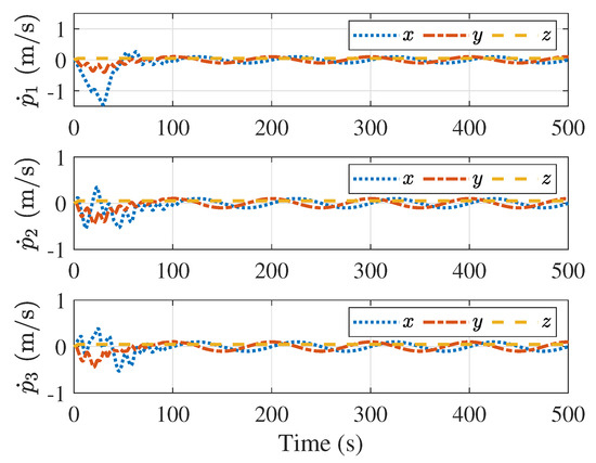
Figure 12.
Velocities of the followers.
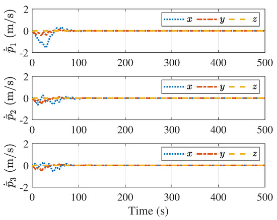
Figure 13.
Velocity errors between the followers and the leader.
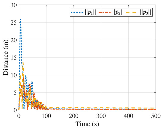
Figure 14.
Distances between the followers and their proxy spacecraft.
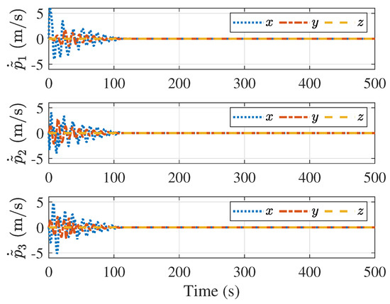
Figure 15.
Velocity errors between the followers and their proxy spacecraft.
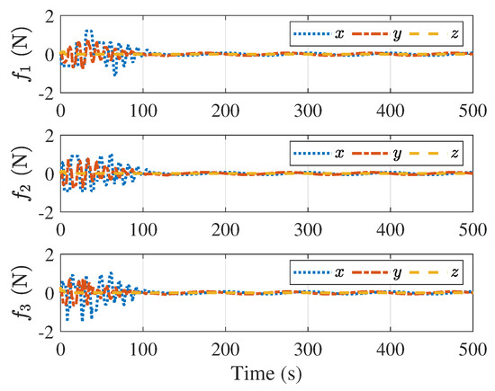
Figure 16.
Control forces of the followers.
5. Conclusions
This paper considered the impact of actuator saturation on connectivity preservation and collision avoidance control of multiple rigid spacecraft. An indirect coupling strategy with a bounded artificial potential function is proposed to overcome actuator saturation constraints. The proposed control algorithm is also applicable to other Lagrangian systems. In future work, the connectivity preservation of a directed graph in the presence of actuator saturation will be considered.
Author Contributions
Methodology, X.X.; Validation, X.X.; Writing—original draft, X.W.; Writing—review & editing, N.H.; Funding acquisition, X.X. All authors have read and agreed to the published version of the manuscript.
Funding
This work was funded by the National Natural Science Foundation of China (No. 62103326), the Science and Technology Foundation of the National Key Laboratory of Aerospace Flight Dynamics (No. 6142210200310), the China Postdoctoral Science Foundation (No. 2021MD703880), the Key Research and Development Program of Shaanxi (No. 2024GX-YBXM-565), the Young Talent Fund of Xi’an Association for Science and Technology (No. 959202313034), and the Scientific Research Program Funded by Shaanxi Provincial Education Department (Nos. 21JK0800 and 21JY033).
Data Availability Statement
The data used to support the findings of this study are available from the corresponding author upon request.
Conflicts of Interest
The authors declare no conflicts of interest.
References
- Liu, G.; Zhang, S. A Survey on Formation Control of Small Satellites. Proc. IEEE 2018, 106, 440–457. [Google Scholar] [CrossRef]
- Scharf, D.P.; Hadaegh, F.Y.; Ploen, S.R. A survey of spacecraft formation flying guidance and control. Part II: Control. Am. Control Conf. 2004, 4, 2976–2985. [Google Scholar]
- Song, Y.; Zhou, Q.; Chen, Q. Control of electromagnetic formation flight of two satellites in low earth orbits. Aerospace 2023, 10, 229. [Google Scholar] [CrossRef]
- Bandyopadhyay, S.; Foust, R.; Subramanian, G.P.; Chung, S.J.; Hadaegh, F.Y. Review of Formation Flying and Constellation Missions Using Nanosatellites. J. Spacecr. Rocket. 2016, 53, 567–578. [Google Scholar] [CrossRef]
- Ivanov, D.; Amaro, G.; Mashtakov, Y.; Ovchinnikov, M.; Guerman, A. Formation Flying Lyapunov-Based Control Using Lorentz Forces. Aerospace 2023, 10, 39. [Google Scholar] [CrossRef]
- Yue, X.; Xue, X.; Wen, H.; Yuan, J. Adaptive control for attitude coordination of leader-following rigid spacecraft systems with inertia parameter uncertainties. Chin. J. Aeronaut. 2019, 32, 688–700. [Google Scholar]
- Felicetti, L.; Palmerini, G.B. Attitude coordination strategies in satellite constellations and formation flying. In Proceedings of the 2015 IEEE Aerospace Conference, Big Sky, MT, USA, 7–14 March 2015; pp. 1–13. [Google Scholar]
- McInnes, C.R. Autonomous ring formation for a planar constellation of satellites. J. Guid. Control Dyn. 1995, 18, 1215–1217. [Google Scholar] [CrossRef]
- Palmerini, G.B. Guidance strategies for satellite formations. In Proceedings of the AAS/AIAA Astrodynamics Conference, Girdwood, AK, USA, 16–19 August 1999; pp. 135–145. [Google Scholar]
- Huang, X.; Yan, Y.; Zhou, Y. Underactuated spacecraft formation reconfiguration with collision avoidance. Acta Astronaut. 2017, 131, 166–181. [Google Scholar] [CrossRef]
- Cao, L.; Qiao, D.; Xu, J. Suboptimal artificial potential function sliding mode control for spacecraft rendezvous with obstacle avoidance. Acta Astronaut. 2018, 143, 133–146. [Google Scholar] [CrossRef]
- Kristiansen, R.; Nicklasson, P.J.; Gravdahl, J.T. Spacecraft coordination control in 6DOF: Integrator backstepping vs passivity-based control. Automatica 2008, 44, 2896–2901. [Google Scholar] [CrossRef]
- Ran, D.; Chen, X.; Misra, A.K.; Xiao, B. Relative position coordinated control for spacecraft formation flying with communication delays. Acta Astronaut. 2017, 137, 302–311. [Google Scholar] [CrossRef]
- Wu, X.; Bai, W.; Xie, Y.; Zhang, X.; Song, T. Predefined-Performance-Based Full-Process Control for Ultra-Close and High-Precision Formation Flying. Aerospace 2023, 10, 152. [Google Scholar] [CrossRef]
- Zou, A.M.; de Ruiter, A.H.; Kumar, K.D. Distributed finite-time velocity-free attitude coordination control for spacecraft formations. Automatica 2016, 67, 46–53. [Google Scholar] [CrossRef]
- Knorn, S.; Chen, Z.; Middleton, R.H. Overview: Collective control of multiagent systems. IEEE Trans. Control Netw. Syst. 2016, 3, 334–347. [Google Scholar] [CrossRef]
- Stephan, J.; Fink, J.; Kumar, V.; Ribeiro, A. Concurrent control of mobility and communication in multirobot systems. IEEE Trans. Robot. 2017, 33, 1248–1254. [Google Scholar] [CrossRef]
- Li, C.; Qu, Z.; Qi, D.; Wang, F. Distributed Finite-Time Estimation of the Bounds on Algebraic Connectivity for Directed Graphs. Automatica 2019, 107, 289–295. [Google Scholar] [CrossRef]
- Ji, M.; Egerstedt, M. Distributed coordination control of multiagent systems while preserving connectedness. IEEE Trans. Robot. 2007, 23, 693–703. [Google Scholar] [CrossRef]
- Cao, Y.; Ren, W. Distributed coordinated tracking with reduced interaction via a variable structure approach. IEEE Trans. Autom. Control 2012, 57, 33–48. [Google Scholar]
- Yi, J.; Li, J.; Zhang, Z. Fixed-Time Connectivity-Preserving Consensus of Periodically Disturbed Nonlinear Multi-Agent Systems with Limited Communication Ranges. ISA Trans. 2023, 138, 291–300. [Google Scholar] [CrossRef]
- Restrepo, E.; Loría, A.; Sarras, I.; Marzat, J. Edge-Based Strict Lyapunov Functions for Consensus with Connectivity Preservation over Directed Graphs. Automatica 2021, 132, 109812. [Google Scholar] [CrossRef]
- Qu, Z.; Li, C.; Lewis, F. Cooperative control with distributed gain adaptation and connectivity estimation for directed networks. Int. J. Robust Nonlinear Control 2014, 24, 450–476. [Google Scholar] [CrossRef]
- Yang, Y.; Shi, Y.; Constantinescu, D. Connectivity-preserving synchronization of time-delay Euler–Lagrange networks with bounded actuation. IEEE Trans. Cybern. 2021, 51, 3469–3482. [Google Scholar] [CrossRef] [PubMed]
- Gasparri, A.; Sabattini, L.; Ulivi, G. Bounded control law for global connectivity maintenance in cooperative multirobot systems. IEEE Trans. Robot. 2017, 33, 700–717. [Google Scholar] [CrossRef]
- Restrepo, E.; Loria, A.; Sarras, I.; Marzat, J. Robust Consensus of High-Order Systems under Output Constraints: Application to Rendezvous of Underactuated UAVs. IEEE Trans. Autom. Control 2023, 68, 329–342. [Google Scholar] [CrossRef]
- Xue, X.; Yue, X.; Yuan, J. Distributed Connectivity Maintenance and Collision Avoidance Control of Spacecraft Formation Flying. In Proceedings of the 2019 Chinese Control Conference (CCC), Guangzhou, China, 27–30 July 2019; pp. 8265–8270. [Google Scholar]
- Ghapani, S.; Mei, J.; Ren, W.; Song, Y. Fully distributed flocking with a moving leader for Lagrange networks with parametric uncertainties. Automatica 2016, 67, 67–76. [Google Scholar] [CrossRef]
- Shi, Y.; Hu, Q. Event-driven connectivity-preserving coordinated control for multiple spacecraft systems with a distance-dependent dynamic graph. IEEE Trans. Cybern. 2021, 52, 12551–12560. [Google Scholar] [CrossRef] [PubMed]
- Xue, X.; Yue, X.; Yuan, J. Connectivity Preservation and Collision Avoidance Control for Spacecraft Formation Flying in the Presence of Multiple Obstacles. Adv. Space Res. 2021, 67, 3504–3514. [Google Scholar] [CrossRef]
- Chen, Z.; Emami, M.R.; Chen, W. Connectivity preservation and obstacle avoidance in small multi-spacecraft formation with distributed adaptive tracking control. J. Intell. Robot. Syst. 2021, 101, 1–23. [Google Scholar] [CrossRef]
- Wei, C.; Wu, X.; Xiao, B.; Wu, J.; Zhang, C. Adaptive Leader-Following Performance Guaranteed Formation Control for Multiple Spacecraft with Collision Avoidance and Connectivity Assurance. Aerosp. Sci. Technol. 2022, 120, 107266. [Google Scholar] [CrossRef]
- Xue, X.; Yue, X.; Yuan, J. Connectivity Preservation and Collision Avoidance Control for Spacecraft Formation Flying with Bounded Actuation. In Proceedings of the 2020 International Conference on Guidance, Navigation and Control, Tianjin, China, 23–25 October 2020; Springer: Berlin/Heidelberg, Germany, 2022; pp. 3685–3697. [Google Scholar]
- Kristiansen, R.; Nicklasson, P.J. Spacecraft formation flying: A review and new results on state feedback control. Acta Astronaut. 2009, 65, 1537–1552. [Google Scholar] [CrossRef]
- Mesbahi, M.; Egerstedt, M. Graph Theoretic Methods in Multiagent Networks; Princeton University Press: Princeton, NJ, USA, 2010; Volume 33. [Google Scholar]
- Horn, R.A.; Johnson, C.R. Matrix Analysis; Cambridge University Press: Cambridge, UK, 2012. [Google Scholar]
- Li, X.; Sun, D.; Yang, J. A bounded controller for multirobot navigation while maintaining network connectivity in the presence of obstacles. Automatica 2013, 49, 285–292. [Google Scholar] [CrossRef]
- Zavala-Rio, A.; Santibanez, V. A natural saturating extension of the PD-with-desired-gravity-compensation control law for robot manipulators with bounded inputs. IEEE Trans. Robot. 2007, 23, 386–391. [Google Scholar] [CrossRef]
- Yang, Y.; Constantinescu, D.; Shi, Y. Connectivity-preserving consensus of multi-agent systems with bounded actuation. arXiv 2018, arXiv:1803.09309. [Google Scholar]
- Wen, G.; Duan, Z.; Su, H.; Chen, G.; Yu, W. A connectivity-preserving flocking algorithm for multi-agent dynamical systems with bounded potential function. IET Control Theory Appl. 2012, 6, 813–821. [Google Scholar] [CrossRef]
Disclaimer/Publisher’s Note: The statements, opinions and data contained in all publications are solely those of the individual author(s) and contributor(s) and not of MDPI and/or the editor(s). MDPI and/or the editor(s) disclaim responsibility for any injury to people or property resulting from any ideas, methods, instructions or products referred to in the content. |
© 2024 by the authors. Licensee MDPI, Basel, Switzerland. This article is an open access article distributed under the terms and conditions of the Creative Commons Attribution (CC BY) license (https://creativecommons.org/licenses/by/4.0/).