1. Introduction
One of the most significant current developments in avionics system architecture is Distributed Integrated Modular Avionics (DIMA). In contrast to the traditional integrated modular avionics approach, DIMA eschews the design concept of centralizing all computing resources in a single cabinet and instead distributes them across various parts of the aircraft. This approach not only enhances flexibility, but also increases the sophistication of the design. The literature [
1,
2] reports that the Distributed Integrated Modular Avionics system has been successfully implemented in A380 and B787 aircraft. Additionally, references [
3,
4] detail the architectural characteristics of DIMA. The open system architecture of DIMA not only provides opportunities for innovation, but has also been advocated by scientific and technological research projects under the EU FP7 [
5,
6], covering typical avionics systems such as the braking and power systems. The literature [
7,
8,
9] details the performance requirements and highlights the current technical limitations of typical avionics systems under the DIMA architecture. It can therefore be concluded that aircraft systems under the DIMA architecture are expected to become the dominant trend in future aircraft system design.
The current approaches to fault propagation analysis for DIMA fall into two categories: manual analysis [
10,
11,
12] and intelligent diagnostic analysis [
13]. In manual analysis, decisions are primarily based on the analyst’s experience and subjective judgment, while intelligent diagnostic analysis relies on the monitoring of fault information and the training of fault models. This automation enhances the analysis and assessment of fault propagation behavior. Wu Yuqian and colleagues [
14] highlight that avionics functional integration often presents cascading failure challenges in typical avionics systems. Consequently, the high degree of coupling between the Core Processing Modules (CPM) in DIMA architecture must be considered, underscoring the importance of establishing a cascading failure propagation model. Cascading failures [
15,
16], which occur due to positive feedback loops and escalate over time, typically initiate with the failure of a single node or subsystem. The failure of a single node leads to load redistribution to the remaining nodes, thereby increasing the likelihood of further system failures. This can lead to a vicious cycle, often described as a snowball effect. The process of analyzing cascade failures is outlined in SAE ARP 4761A. It begins by determining the initial conditions, continues by delineating the cascade’s range of influence, and concludes with an analysis of the outcomes. Motter et al. [
17] proposed a dynamic model for describing cascade failures, now widely used in complex network robustness analysis. Zheng et al. [
18,
19,
20] developed a cascade failure model by incorporating the congestion effect, which assesses node load in a congested complex system and elucidates the cascading relationships among nodes. Zheng Jianfeng [
21] utilized statistical physics, operations research, and computer simulations to explore traffic distribution, congestion, and cascading failure behaviors in typical complex networks, focusing on a discrete time and state. It is proposed that the time scales of cascading failures be considered in studies of typical complex network systems. Xiang Chenyang [
22] applied Floyd’s algorithm to analyze system coupling correlations and established a structural model of fault propagation for an all-electric brake system. Based on this, the probability of fault path propagation and the system edge median were combined to develop a model that quantifies the system’s fault propagation intensity and identifies the most critical fault propagation path.
However, studies addressing the impact of cascading failures on avionics systems from a discrete time dynamic perspective are lacking. Event-based modeling of discrete systems effectively captures the dynamics of fault occurrence and propagation, offering a more natural and accurate description of fault behavior. In discrete systems, state changes typically occur at specific, discrete intervals, aligning closely with the characteristics of fault propagation. This suggests that fault occurrences and their effects are sudden and well-defined, as opposed to being gradual and continuous. Consequently, discrete systems are more apt for describing and analyzing fault propagation behaviors compared to continuous systems. However, it is essential that avionics systems are analyzed on a time scale due to their dynamic nature.
In light of the aforementioned circumstances, we proposed the development of a cascade failure propagation model based on a discrete time dynamic system. This model will facilitate the study of failure propagation behavior in aircraft avionics systems under the DIMA architecture. The model development will adhere to the cascade failure analysis method described in SAE ARP 4761A. The fundamental concept involves utilizing the conditional failure probability between modules to depict the cascade relationship among DIMA modules. The probability that a DIMA module is in a failure state at a specific point in time is considered a state variable of the discrete dynamic system.
The rest of this paper is organized as follows.
Section 2 establishes the hierarchical architecture of DIMA.
Section 3 constructs a cascade failure propagation model using a discrete time dynamic system.
Section 4 validates the proposed method via an illustrative analysis of an aircraft’s all-electric brake system.
Section 5 analyzes and discusses the experimental data and proposes a method for improvement.
Section 6 summarizes this paper.
2. DIMA Hierarchical Architecture Construction and Cascade Effect Analysis
2.1. DIMA’s Layered Architecture
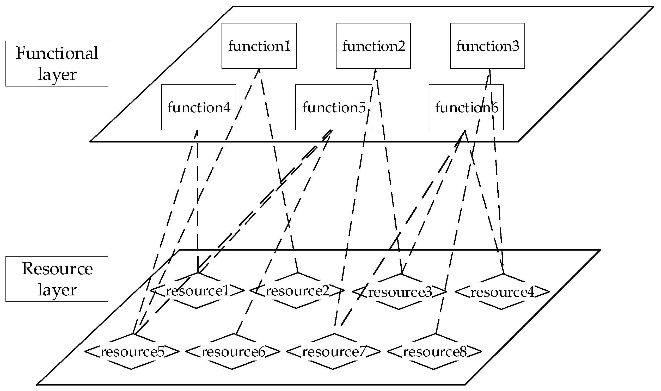
DIMA represents the latest advancement in modern avionics system architecture. It is designed for enhanced flexibility compared to traditional modular avionics systems, emphasizing the versatility, extensibility, and adaptability of system modules. In this open system architecture, functions from aircraft electromechanical, avionics, and other systems increasingly integrate and intersect. For avionics systems with stringent real-time requirements, achieving low-latency, low-jitter, and deterministic data transmission is essential, while also considering functional implementation. The adoption of DIMA technology provides robust computational support to enhance the real-time performance of avionics systems. Based on this, the layered architecture of DIMA is outlined in
Figure 1, reflecting its distinctive architectural features.
In the context of distributed and integrated avionics systems, a layered architectural design is employed, which includes the system’s functional and resource layers. From this architectural perspective, the functional layer consists of related subsystem functions, serving to simplify the system. In contrast, the resource layer utilizes its robust public computing resources to ensure the rapid loading of control algorithms and the output of control commands. Resource scheduling is based on mapping rules and activities linking the functional and resource layers. This primarily involves the correspondence between functions and resources, as well as between signals and links.
The system design should serve as a starting point, referring to the design criteria of a typical avionics system [
23,
24], which involves requirements for resources, interfaces, performance, and security. Based on the characteristics of the DIMA platform, the core functions of a typical avionics system need to be structured. Furthermore, the correspondence between the functional and resource layers refines the core functions and guides the analysis of future interactions within avionics systems at the resource layer.
- b.
Resource Layer
To realize the above functions, core processing modules in the resource layer must be employed to provide the necessary computational power for functional algorithms or the control cycles of a typical avionics system. These processing modules deploy functionality as required by the application. To facilitate hierarchical modeling and correlation analysis in avionics systems, it is recommended that only one functional application is run per region, without spare modules. Furthermore, establishing correspondence between the functional and resource layers requires considering the correlations among different CPMs, as various functions may share the same CPM.
2.2. Avionics System Cascade Effect Analysis Process
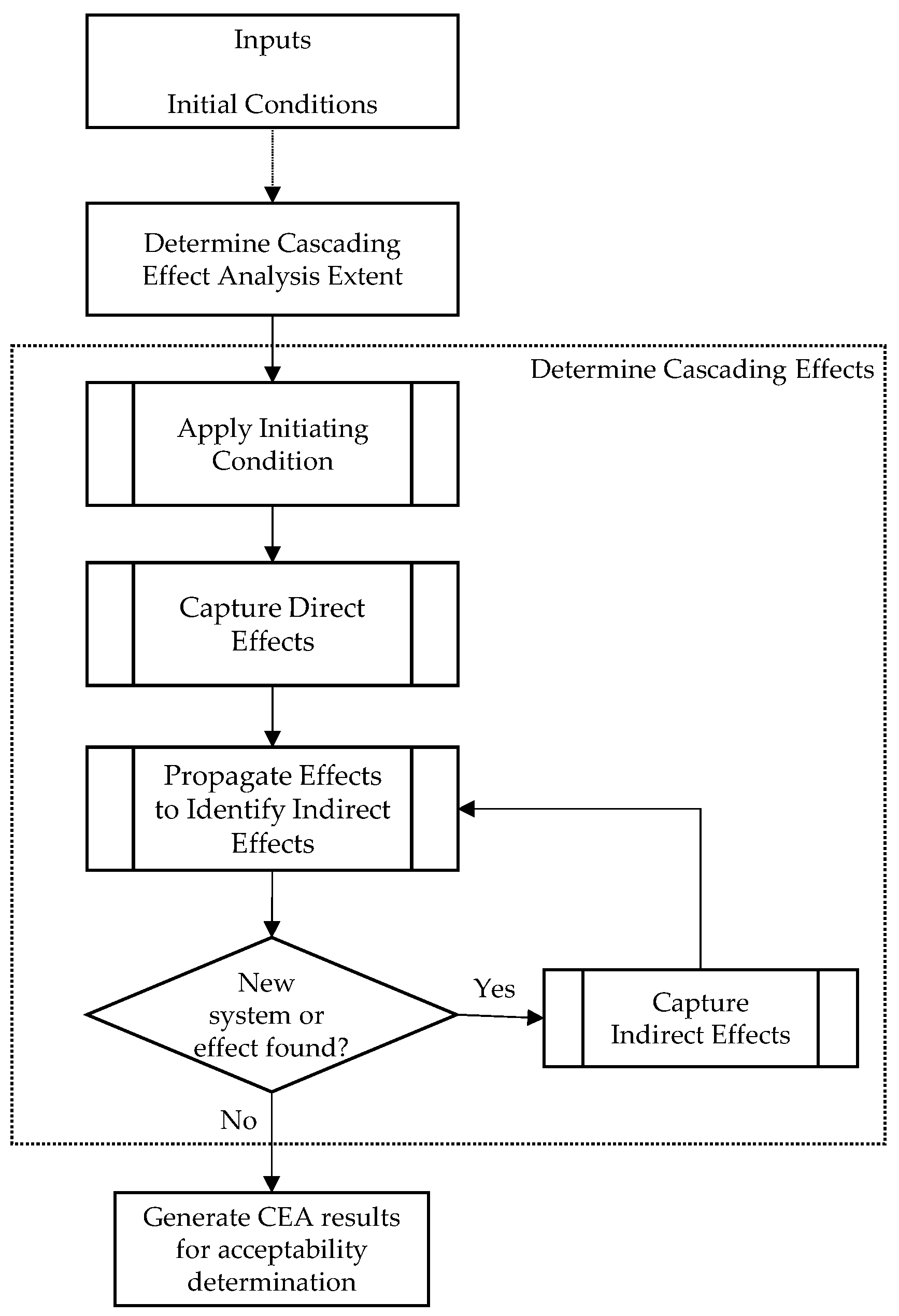
The document SAE ARP 4761A emphasizes that cascade effects within and between systems are crucial when analyzing the propagation of failures in aircraft avionics systems. Cascade Effect Analysis (CEA) is a bottom-up qualitative analysis methodology that evaluates an initial condition (e.g., a failure condition, a failure mode, or a combination of failure modes) and captures the overall effect of that initial condition on the aircraft. This involves an iterative process that identifies both the direct and the indirect effects propagated due to system dependencies. All systems, whether directly or indirectly connected to the system affected by the initial condition, are considered. Cascading effects analysis supports any analysis requiring identification of multi-system effects at an aircraft level or for a specific initial condition. The effects of each initial condition are fed back to the source analysis.
Cascade effects analysis is conducted under an initial condition, which may include a failure condition, a failure mode, or a combination of failure modes.
Figure 2 provides a summary of the cascade effects analysis steps and their sequence, with the term ‘system’ replaced by ‘device’ or ‘module’ in each activity to adapt to lower-level activities.
Once the system architecture and initial conditions are established, the scope of cascading failures is initially determined. The sphere of influence is determined by identifying systems either directly affected by, or indirectly connected through, the initial condition. This step focuses on identifying and documenting the interaction pathways between initial and potential system interfaces. The cascading effects of the aircraft are identified through an iterative process, culminating in the output of the cascading effects analysis results. The output should include the initial conditions, the range of analyzed effects, a list of systems associated with the initial conditions and their effects, and the assumptions used in the analysis, each tailored to the specific cascade effect.
3. Cascading Failure Propagation Modelling for DIMA
3.1. DIMA Network Topology
Understanding the role of network topology [
25,
26] significantly facilitates the study of complex system problems. In the DIMA model, a network topology graph represents the cascade relationships within the avionics system. The graph consists of nodes and directed edges. Nodes represent the system’s constituent modules, and directed edges depict the cascade relationships between these nodes. The overall performance of an avionics system depends on the operational status of each module. System performance can be described, analyzed, and evaluated across multiple dimensions. Among these dimensions, the network connectivity index is commonly used to gauge the system’s overall performance. This index reflects the system’s connectivity. Within the proposed modeling framework, this index can be replaced with other performance indicators to assess various system dimensions [
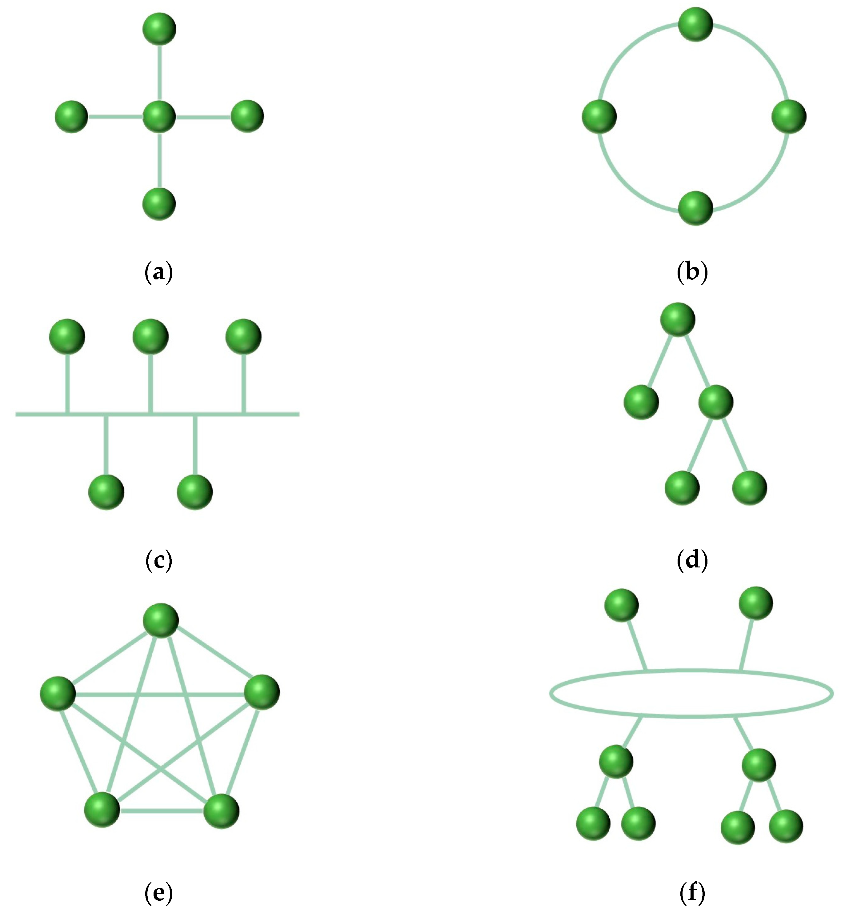
27]. Depending on the nature of the dependencies between modules, various relational networks can be formed [
28], including star, ring, bus, tree, mesh, and hybrid structures, as shown in
Figure 3.
Most network topologies in DIMA are mesh structures. Concurrently, the network topology method quantitatively characterizes the association strength between two system modules based on failure condition probabilities, easily integrating with module failure probabilities.
3.2. Failure Analysis of DIMA Module Based on Discrete Dynamic System
DIMA involves the evolution of certain quantities over time, where the state of the system evolves in discrete time steps, i.e., discrete dynamic systems. These quantities are referred to as state variables. When modelling DIMA as a discrete dynamic system, a set of sequences of system states over time can be determined. The state changes of the system conform to certain rules, which enable future states to be determined from a given initial state. A scalar between 0 and 1 is employed as the state variable of the system, which represents the probability that the module will be in a faulty state at a given point in time.
The probability in question may be defined as the state variable of a system node, where and denotes a discrete time set.
For the sake of convenience, the setting of in the model can be accomplished through the use of different time scales, contingent upon the specific requirements of the model in question. When there are nodes in the system, the state variable of the system is recorded as at time , where .
In light of the aforementioned definition, the approximate model of the DIMA discrete time dynamic system can be described as follows:
where
is the initial setting and
is a nonlinear mapping.
At a defined time
, the events at node
in the system can be classified into the following types: failure events
, direct failure events
, cascading failure events
, and cascading failure events
due to the failure of node
. For a failure event
, the union of two failure events,
and
, is considered. The cause of direct failure event
is mainly the failure of a system node due to causal factors. Furthermore, the cascade failure event
is a concatenation of the cascade failure sub-events
. The cascade failure sub-event
is a failure of the upstream node
, which leads to a cascade failure of node
. The mechanism and probability of cascade failure events are discussed in the following sections. Consequently, the probability of
occurring can be expressed as:
As events
and
are independent of one another, they can be obtained.
In accordance with the definition of the state variables of the system presented in the preceding section, it can be demonstrated that
Subsequently, if only DIMA is deemed to have failed at the initial stage, then
. Furthermore, it can be demonstrated that
3.3. Construction of DIMA Cascade Failure Propagation Model Based on Discrete Dynamic System
In order to construct a DIMA cascading failure propagation model based on discrete dynamical systems, it is necessary to assess and determine the probability of direct failure of module in DIMA at a given point in time. This is done by considering the type of failure and the type of facility.
In the event that a single node
is associated with
, the probability of node failure due to cascade is
. The following equation is therefore valid:
where
denotes the probability that node
associated with node
fails at moment
.
denotes the cascading failure event at node
, and
denotes the cascading failure event at node
due to node
. Given that
is the only node associated with
, the following relationships are to be established:
where
denotes the association between nodes
and
. The cascade failure event
of node
is initiated by the failure
of node
.
In the event that multiple nodes within a network are associated with node
, for example, nodes
and
collectively influence node
, the following applies:
where
denotes a cascading failure event of node
due to node
and
denotes a cascading failure event of node
due to node
.The failure of node
occurs subsequent to the event
, which disables node
. Concurrently, the failure of node
occurs at the same time as event
, which also disables node
. In other words, whenever one of node
and node
fails, node
is affected. Therefore, it can be obtained:
In consideration of the values of
and
, and the occurrence of state transfer at discrete time
, the probability of cascade failure for node
is as follows:
In a similar manner, if there are
nodes
associated with node
,
For any node connected to , the conditional probability of failure indicates that the cascading failure event of node is triggered by the failure of node . The conditional probability of failure is known to have a value between 0 and 1. The closer the value of is to 1, the stronger the correlation between the nodes. This implies that the failure of the upstream node is more likely to be transmitted to the associated node , which will result in the failure of the associated node . When , it signifies that the two nodes are fully correlated, and the failure of the upstream node will lead to the failure of the downstream associated node . Conversely, when , it indicates that both parties are uncorrelated and independent of each other. The conditional probability of failure, denoted by , represents the strength of association between two nodes, and .
The actual operational scenarios of DIMA may be more complex; for instance,
may vary with time or events. However, the objective of this paper is to propose a generalized model to study the risk propagation of DIMA cascade failures and to address the issues mentioned earlier. Therefore, the focus of this paper does not involve the determination of conditional probabilities. For the purposes of this paper, it is convenient to set the conditional failure probability as a known fixed value that does not vary with time. This is consistent with the majority of international studies [
29,
30]. The conditional probability of failure between DIMA modules can then be calculated based on the correlation relationship between the modules and the strength of the correlation. To illustrate, consider a system comprising
nodes, where nodes
and
are linked. The probability that the failure of node
leads to the failure of node
is denoted by
. This probability may be abbreviated as follows:
This yields
, which characterizes the effect of node
on node
in terms of probabilities. If a system has
nodes, there are
associations, i.e., there are
conditional probabilities. Consequently, a
cascade matrix,
, can be obtained as follows:
If DIMA contains
modules at a given moment
, the state variables of its discrete dynamical system correspond to
. At the subsequent moment
, the propagation of faults is considered, but the occurrence of direct fault events is not taken into account. The nonlinear mapping
is as follows:
where
is the initial value of the system state variable. In order to simulate the failure modes of DIMA, it is possible to set different initial values according to the type of failure in question. Similarly, when evaluating the module cascade characteristics, the initial values can be changed as needed. In conclusion, the DIMA cascade failure propagation model based on a discrete dynamic system has been established.
4. Validation of Cascade Failure Propagation Models for All-Electric Brake Systems under DIMA Architecture
The mapping relationship between the all-electric brake system and the resource layer is detailed based on the existing model of the all-electric brake system under the DIMA architecture [
31], as illustrated in
Table 1.
The function–resource mapping relationship of the all-electric brake system, detailed in
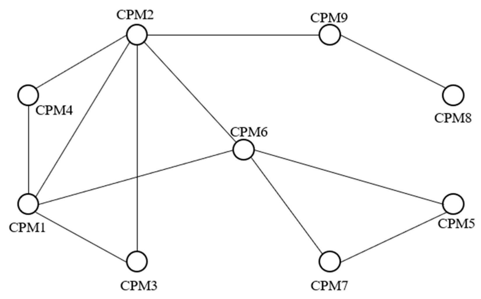
Table 1, facilitates the derivation of the network topology diagram, as illustrated in
Figure 4. The system model includes nine CPM modules and thirteen directed edges, where the cascade relationships between CPMs are represented by these edges. In the figure, straight lines represent bidirectional edges. For interrelated modules
and
, the probability of module
failure caused by module
failure is
. Based on the aforementioned assumptions, the conditional probability
of a cascade failure between CPMs is set to
where
N denotes the number of directed edges in the fault model. In order to facilitate the numerical calculation,
is set to
, in order to make the results more intuitive. Meanwhile, the average failure probability of each CPM of the system at a certain moment
is defined as the failure risk of the all-electric brake system. This can be reasonably assumed to be
under the actual operating conditions of the all-electric brake system, as stated in the paper [
32].
In this context, the probability of failure of the all-electric brake system
can be expressed as
Subsequently, the failure probability
of each CPM in the aforementioned equation is weighted according to its importance. Alternatively, a new performance evaluation function based on failure probability may be proposed. However, evaluating the performance of the all-electric brake system is not the focus of this study. Therefore, the failure modeling of the all-electric brake system utilizes the two aforementioned metrics to approximately describe the changes in overall system performance. Two types of failure modes are considered. The first is an initial CPM failure, which leads to the system module being affected by cascading failures but not by direct external failure events. This is represented by
Failure mode 2 is characterized by the continued impact of an external direct fault event on the all-electric brake system following the cascading failure propagation, which is represented by the following parameter:
To identify the cascading fault propagation capabilities of each CPM in an all-electric brake system, only fault mode 1 was considered. It was assumed that, under the initial fault event, only one CPM would fail while the other CPMs would remain operational. A series of numerical experiments were conducted for each CPM, with the aim of recording the system’s state changes over the first . The initial fault occurrence in CPM1 served as a case study to document the state variables of the all-electric brake system at various times.
When
, it is known that
That is to say, CPM1 fails at the initial moment, and in the following time, no external direct failure event
occurs in the system, and it is affected only by the cascading failure event
. Therefore,
. Transitioning from the initial to the subsequent moment, as illustrated in
Figure 4, it becomes evident that the risk of failure in CPM1 is transferred to CPM2, CPM3, CPM4, and CPM6. To illustrate this point, consider CPM2; from Equations (10) and (6), it is evident that
Consequently, the probability of failure for each CPM at various moments can be calculated. Currently, the international standard requires aircraft maintenance after 24,000 flight hours. Therefore, to ensure comprehensive fault analysis, the simulation period should exceed this duration. Accordingly, we selected 50,000 flight hours for our simulation research. As illustrated in
Figure 5, the cascade failure propagation model for the all-electric brake system under the DIMA architecture is displayed, covering
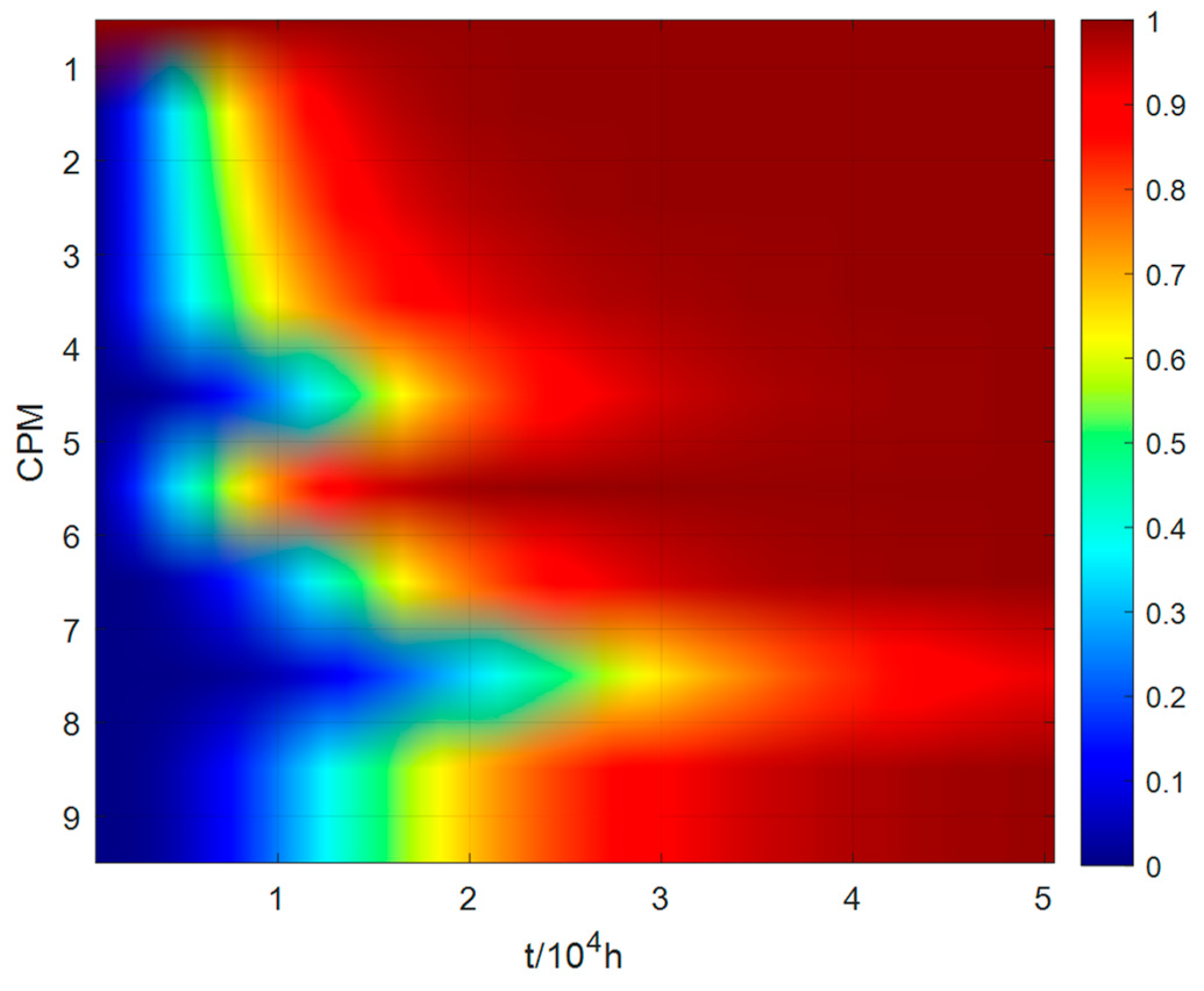
of operation starting from the initial failure of CPM1. In the figure, the color of each CPM changes according to the probability of failure. The color shifts from blue to red, signifying a change in the failure probability of a CPM from 0 to 1.
Table 2 lists the specific values of the system state variables at ten-moment intervals under the initial failure state of the CPM1 node. As shown in the accompanying image and table data, the state variable of CPM1 consistently equals 1, indicating a complete failure, consistent with the initial failure condition of CPM1. The failure probabilities of CPM2, CPM3, CPM4, and CPM6, directly linked to CPM1, increase more rapidly than that of CPM8, which has a weaker connection to CPM1.
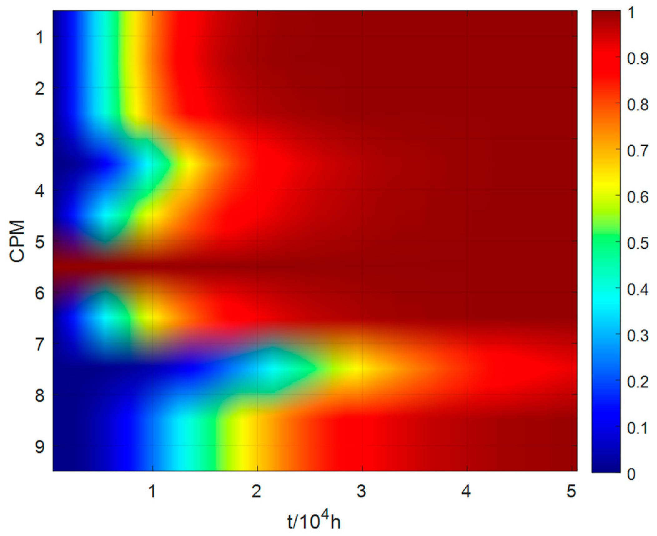
The following section details the cascade failure propagation model of the all-electric braking system under DIMA architecture over a
operation period, starting with an initial failure in module 6, as depicted in
Figure 6.
Table 3 lists the specific values of the system state variables at each of the ten moments following the initial failure of the CPM6 node. As shown in the accompanying image and table data, the state variable of CPM6 consistently registers as 1, indicating a complete failure, consistent with the initial condition. Similarly, this failure probability affects CPM1, CPM2, CPM5, and CPM7, which are directly linked to CPM6. The failure probabilities of CPM3 and CPM4 increase more rapidly due to their direct links to CPM1 and CPM2. Consequently, the failure probabilities of systems indirectly associated with CPM6 and CPM4 escalate more quickly. Additionally, the high indirect correlation with CPM6 leads to a faster increase in its failure rate over time. In contrast, CPM8, with its weaker correlation to CPM1, exhibits a slower increase in failure probability.
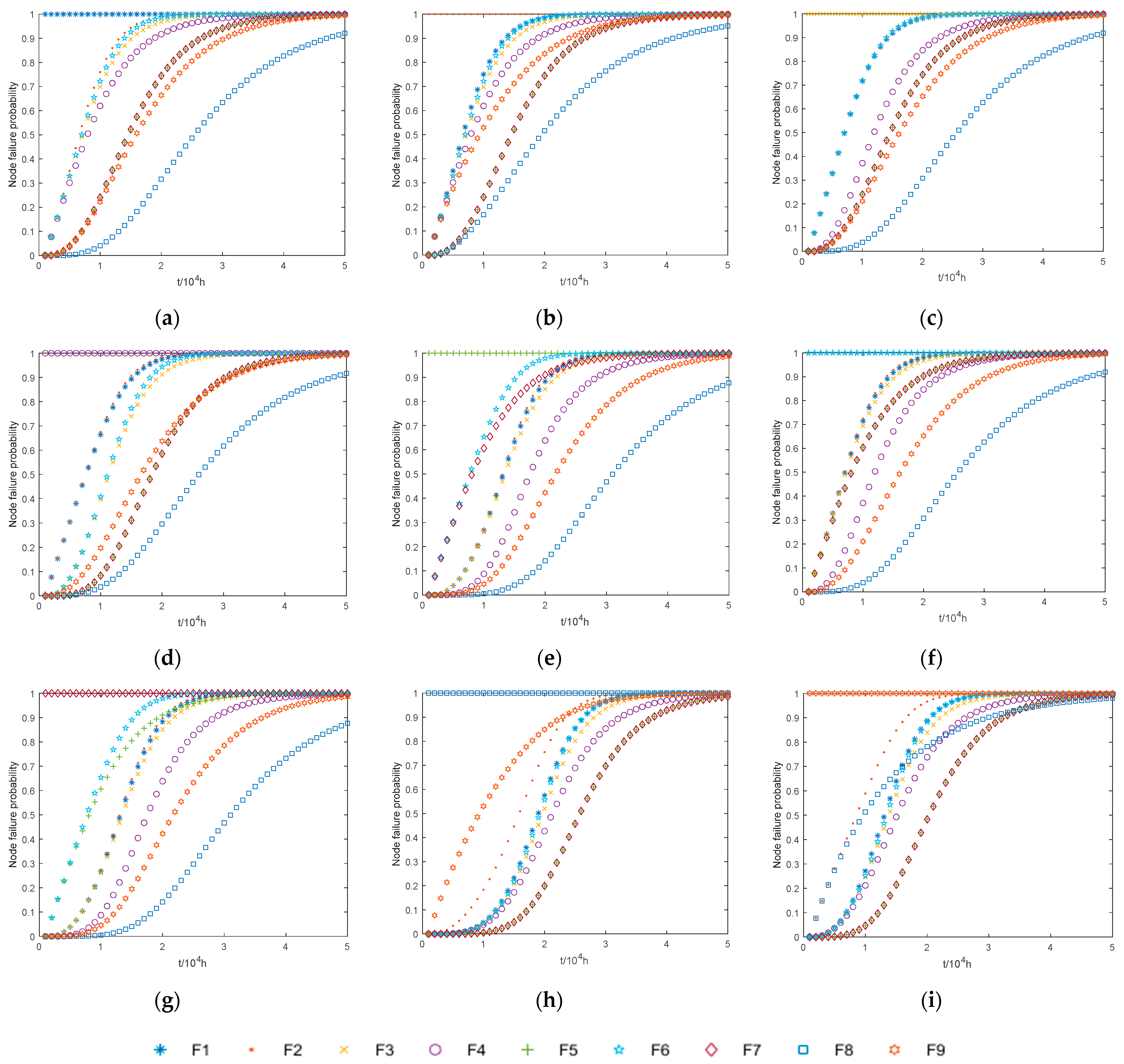
Subsequently, using Equation (14), the initial moment of failure was simulated for each of the nine CPMs, with system state changes recorded over a
period. As shown in
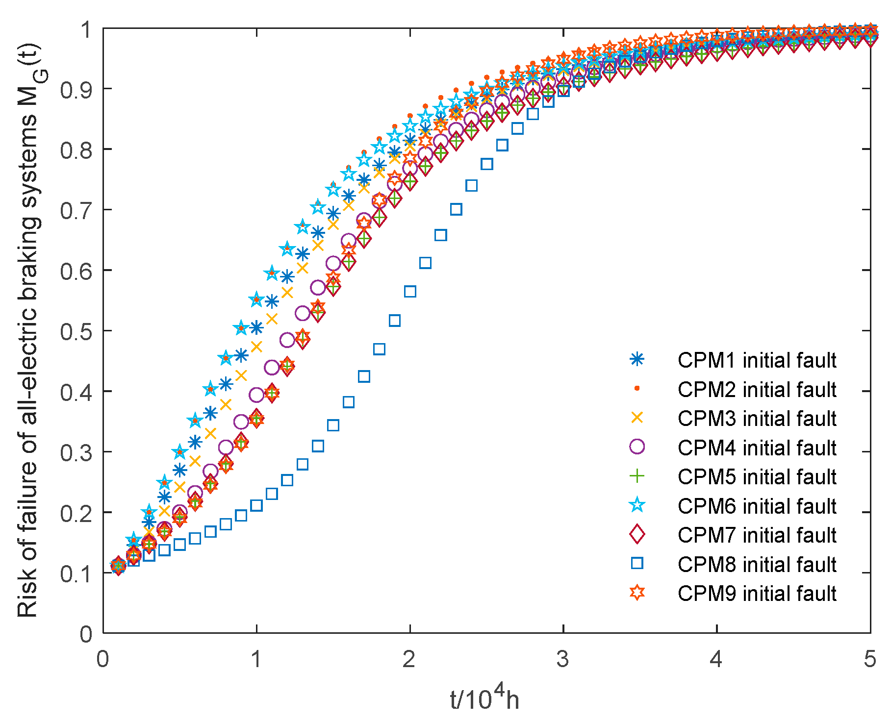
Figure 7, the curves depict how the probability of failure for the system’s CPMs increases over time. Subsequently, using Equation (16), the failure risk of the all-electric brake system, denoted as
, can be calculated.
Figure 8 illustrates the risk of failure of the all-electric brake system under different initial conditions. As can be seen from the figure, the fault risk
grows most rapidly at the initial failure of CPM2, followed by the initial failure of CPM6. In contrast, the risk of failure
grows most slowly when CPM8 has an initial failure.
6. Conclusions and Future Works
This paper integrates the architectural features of an avionics system under the DIMA architecture to construct a hierarchical model from the system’s function and resource layers. This model establishes a function–resource hierarchy that lays the foundation for analyzing the impact of failure propagation. A general model was proposed to examine the risk propagation in DIMA cascade failures, utilizing the cascading failure analysis method from SAE ARP 4761A to study fault propagation in discrete dynamic systems. DIMA module failure events were defined, with conditional probabilities of inter-node failures used to depict cascade relationships. A cascade failure propagation model was constructed for avionics systems under the DIMA architecture using discrete dynamic systems to represent cascade relationships over time. The state variables of the all-electric brake system under the DIMA architecture were calculated following the initial failure of each CPM module, and subsequently, the failure risk under various initial conditions was assessed. Key nodes of failure propagation and system vulnerability were identified in the all-electric brake system, and the validity and accuracy of the proposed method were confirmed. This study confirmed that within the system, CPM2 and CPM6 are particularly vulnerable to failure propagation, and the automatic brake function exhibits notable susceptibility. Analysis indicates that the system’s failure rate increases significantly after two hours of operation, underscoring the necessity of maintenance prior to this threshold to reduce risks. This maintenance strategy is in line with current international aircraft maintenance regulations, affirming its relevance and applicability. Furthermore, the method developed in this paper can apply in the early stages of DIMA resource allocation, thereby enhancing security and aiding in the design of DIMA systems. These findings not only validate the proposed method, but also suggest its potential for broader application in similar contexts.
With the continuous development of avionics systems, the architecture is evolving from a purely integrated framework to a hybrid architecture that combines both integrated and federate architectures. In the future, this method should be refined to suit avionics systems within such a hybrid architecture.
